KEB COMBIVERT F5-A,-E,-H 4.0. APPLICATION MANUAL (2008) - page 15
Positioning and Synchronous Control
7.12 Positioning and synchronous control
7.12.1Limit switch
7.12.1.1
Hardware limit switch
The inputs connected to the functions "32: forward" (limit switch right) and "64: backward" (limit switch left) in
di.11...22 serve as hardware limit switches.Therefore, the rotation setting via terminals (oP.01 "rotation source"
= 2...6) may not be used if the limit switch function is to be used.
To protect against cable breakage, an unconnected input means that the drive has run onto the limit switch.
Attention: Only the limit switch for the current direction of rotation is ever evaluated, i.e., for clockwise
rotation, only the right limit switch is considered and the left limit switch is ignored. The analog
applies to counter clockwise rotation. Therefore, the limit switch can act only if the drive runs in
the correct sense of rotation and the connections of the limit switches are not interchanged. Fur-
thermore, one must ensure that the drive stops at the limit switch. If the limit switch is overrun, a
new positioning in the disabled direction can be carried out.
The response to the error (the run-on to the limit switch) is set in parameter Pn.07 "Proh. rotation stopping
mode". Possible responses are, e.g., triggering of an error or emergency stop (see chapter 7.15 "protection
functions").
Note:
If a function with "AutoRestart" (automatic restart) is chosen as the response, the status shown
only during breaking (display by ru.00 "inverter state" or by digital output) is "Warning! disabled
direction of rotation".Afterwards, the status changes to "ready for positioning" again.
If a function without AutoRestart is chosen, the error-/ warning- message remains displayed until
reset. Afterwards, the status changes to "ready for positioning" again, even if the drive still points
in the direction of the limit switch. The error-/ warning- message is set again only at the next
"start positioning" command.
7.12.1.2
Software limit switch
The software limit switches complement the function of the hardware limit switch.
They are active only after an approach to reference point or the setting of reference points, respectively (see
chapter 7.12.2 approach to reference point). In contrast to hardware limit switches, the software limit switches
can lose their protective function by, e.g., a faulty approach to reference point or a faulty position correction.
Their advantage is that they cannot be overrun.
For a positioning whose target lies outside of the permissible range, the "start positioning"-commands are igno-
red. The permissible range lies between PS.15 "limit switch left" and PS.16 "limit switch right". The software
limit switches are active in the vector controlled operation, the synchronous mode, the positioning mode, and
the contouring mode.
The response to the error (running onto the limit switch) is specified in Pn.66 "software limit stopping mode".
Possible responses are, e.g., triggering of an error or emergency stop (see chapter 7.13 "protection func-
tions").
Note: If the chosen response is a function with "AutoRestart" (automatic restart), then neither does the status
show "warning! disabled direction of rotation" nor is the switching condition "quick stop/ error" set. Cause: As
soon as the setpoint speed is equal to zero, the drive does not run in a disabled direction of rotation anymore,
and the malfunction is reset automatically. The drive also displays "ready for positioning", but does not react to
"start positioning" commands anymore as long as the target position lies outside the permissible range.
If a function without AutoRestart is chosen, the error-/ warning- message remains displayed until reset. After-
wards, the status changes to "ready for positioning" again.
Page7.12 - 4
Positioning and Synchronous Control
7.12.2Approach the reference point
For an approach to reference point, the following conditions must be met:
● program and connect an input as reference point switch(PS.18). The same input can also be used
as a limit switch. Since the limit switches are "zero active" for protection against cable breakage, the
reference switch, in this case, is also "zero active".If the reference switch is connected to its own input,
it is "one active".
● Define an input for the start of the approach to reference point (with PS.19/ only necessary in approach
to reference point mode 1).
● connect the limit switches to the inputs programmed with the functions "32: forward" and "64: back-
ward" in di.11...12 (forward = right limit switch / backward = left limit switch).If the limit switches are to
be omitted (e.g., during round table applications), no input may be occupied with the functions "for-
ward" or "backward".
● The approach to reference point must be activated in item "approach to reference point mode" of pa-
rameter PS.14.
7
Page7.12 - 5

Positioning and Synchronous Control
7.12.2.1
Approach to reference point / modes
There are 3 different Modes of position reference:
PS.14 Mode of position reference
Bit
Meaning
Value
Explanation
0: off
No approach to reference point
1: no auto-
Approach to reference point is started via digital input. The input is
start
defined with PS.19.
The approach to reference point is carried out automatically during the
first "start positioning” command after "power on", even if the positio-
ning mode has not been activated yet (input with function "Positioning
/synchronous activation" not set). If the approach to reference point is
interrupted (e.g., by switching off the control release), all other "start
2: autostart
positioning" commands also start an approach to reference point. Has
the reference point search been completed once, no approach to re-
ference point can be initiated with "start positioning" anymore. If, addi-
tionally, an input is occupied with the function "approach to reference
point", this input is also active.
Mode of positi-
0/1
The software limit switches are active immediately (if programmed
on reference
in Pn. 66), the switching condition "approach to reference point com-
pleted" is met.The value for the actual position (ru.54) is generated as
follows:
● Encoder without absolute position information (e.g., incremen-
tal encoder): After "power on" the actual position is = the last acquired
3: last positi-
actual position before "power off". To ensure that the position is cor-
on (at power-
rect, the encoder may not turn anymore after power off.
on-reset)
● Encoder with single-turn absolute position information (e.g., re-
solver): After "power on", the position is read out by the encoder within
one revolution, the count of whole revolutions is taken from the last ac-
tual position before "power off". To ensure that the position is correct,
the encoder may turn maximally ½ revolution after power off.
● Encoder With multi turn absolute position information:
The current actual position is read from the encoder after "power on".
In mode 1 and 2, the approach to reference point is started on the rising edge of input "start approach to refe-
rence point" (mode 1) and "start positioning" (mode 2), respectively.
The approach to reference point starts at the speed set in PS.21 "reference speed". The direction of rotation
which is used first for the reference point search (the preferred direction f rotation) is set by the sign of PS.21 .
A positive sign means the drive first looks for the reference point switch in the clockwise direction of rotation.
The acceleration / deceleration ramps during the approach to reference point are defined via PS.20 "approach
to reference point ramp time" rather than the OP-parameters.
Attention: the ramp time and the approach to reference point speed must be chosen so that the drive can stop
and reverse as long as the reference point switch is active. Otherwise, faulty referencing can occur (e.g., stop
on the wrong side of the reference point).
To achieve the most precise referencing possible, an "approach to reference point free drive-speed" can be
programmed for free driving of the reference switch in PS.22 . If this parameter is set to "0:off", the free drive-
speed is taken as ¼ of the approach to reference point speed (PS.21) .
At the reference point, the actual position is overwritten with the value of PS.17 "reference point".
Page7.12 - 6
Positioning and Synchronous Control
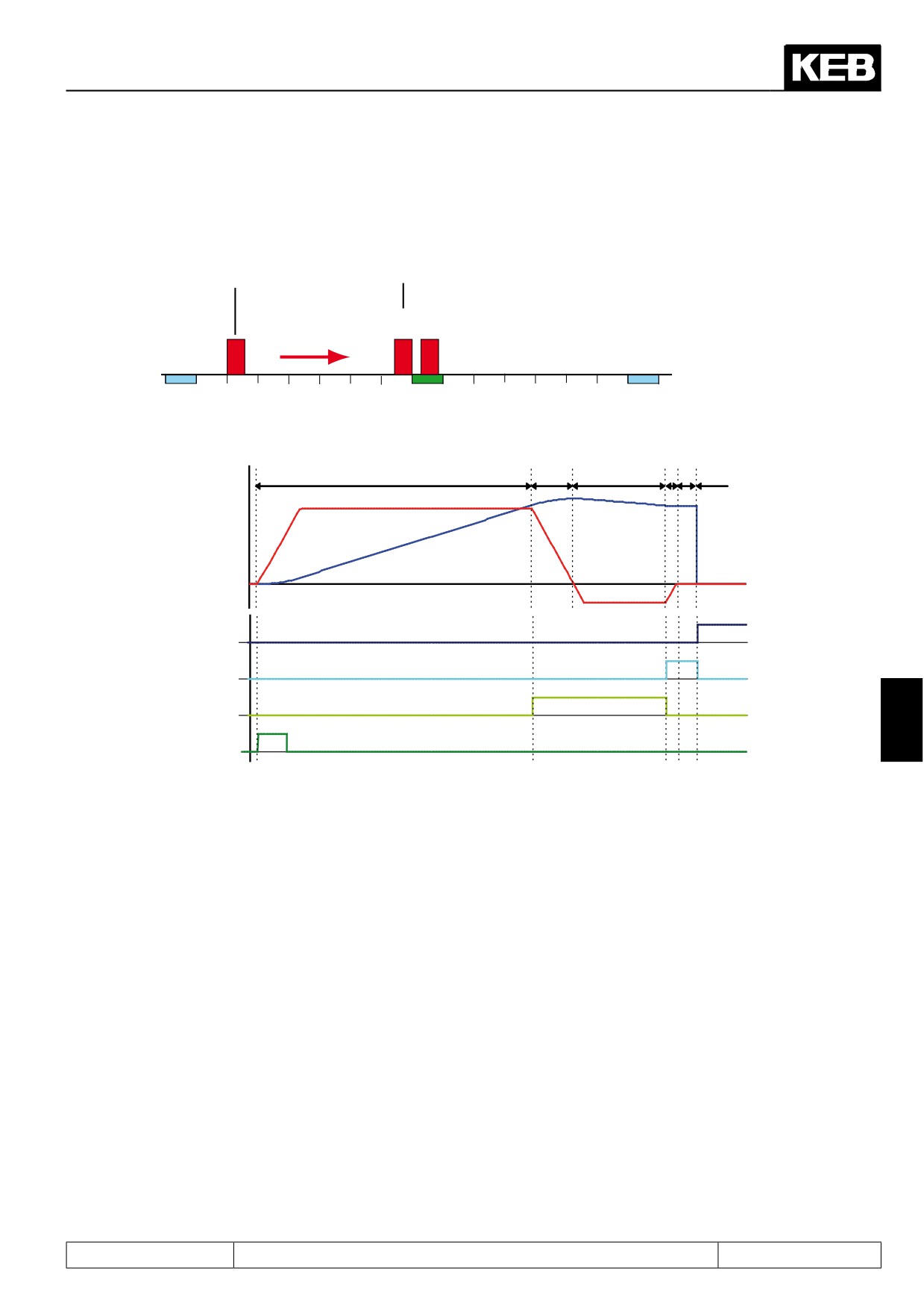
The two following figures show an exemplary approach to reference point process. The further possibililties
programmable in PS.14 are shown later in this chapter.
Ref. point
search com-
pleted
Start
PS.21: Approach to ref.point
speed = positive
5/6
2/3
1
0
1000
2000
3000
4000
5000
6000
7000
8000
Limit switch left
Ref. point
Limit switch
switch
right
1
2
3
4
5
6
ru.02: Ramp
output display
ru.54: Actual
position
Approach to ref.
point completed
Target window
reached
Ref. point
switch
7
Start approach
to ref. point
1. PS.21 = positive, i.e., the drive accelerates with the ramp from PS.20 and searches in the direction of
clockwise rotation for the reference switch
2. Stopping at the reference switch
3. Free driving of the reference switch with free drive-speed (PS.21 / PS.22)
4. Stopping of the drive with ramp from PS.20
Setting of the signal "target window reached"
5. Wait for the damping period of 100ms
6. Overwrite the current actual position (ru.54) with the reference point position(PS.17)
Resetting of the signal "target window reached"
Setting of the signal "approach to reference point completed"
Stopping of the drive left of the reference point (programmable via PS.14)
Page7.12 - 7

Positioning and Synchronous Control
7.12.2.2
Approach to reference point / stopping point
PS.14 determines which side of the reference point switch the drive is positioned on after the approach to re-
ference point. Even if, after the free driving of the reference switch, positioning is to occur based on the zero
signal, "stopping point " determines if the first null signal is to be driven on at the right or left of the reference
switch.
The adjustment is only considered if the reference point switch serves not simultaneously as limit switch.
PS.14 Mode of position reference
Bit
Meaning
Value
Explanation
Stopping
0: right
Stop on the right side of the reference point switch
3
point
8: left
Stop on the left side of the reference point switch
7.12.2.3
Approach to reference point / stop at zero signal
An approach to reference point that depends only on the initiator signal of the reference point switch is insuf-
ficiently precise for many applications. Therefore, the possibility exists to couple the reference point with the
marker pulse of the encoder.
To that end, positioning after the free driving of the reference switch is done on the marker pulse of the encoder
and the current actual position=marker pulse is then overwritten with the reference point value.
With "stop at null signal= 4: yes" this function is activated.
Additionally, two monitoring functions can be switched in with bit 4 "error if no zero signal" and bit 8 "Verify zero
signal". These are only active if "stop at null signal= yes" is programmed.
PS.14 Mode of position reference
Bit
Meaning
Value
Explanation
0: no
The drive stops directly after free driving of the reference point switch.
The drive positions on the null signal of the encoder after free driving of
Stop at zero
2
the reference point switch at the free drive-speed. If during the drive to the
signal
4: yes
reference switch no null signal was received, the behaviour of the drive is
determined by bit 4 "error if no zero signal".
If, during the reference point search, no null signal is recognised, the drive
rotates maximally another two revolutions at the free drive-speed to locate
the null signal. If the null signal is found, the drive reverses and drives back
to the reference point switch. Positioning on the null signal is executed after
0: off
that.
Error, if no zero
If no null signal is recognised during the null signal search, the inverter re-
4
signal
ports "error! Encoder 1" respectively "error! Encoder 2" (E.EnC1 respectively
E.EnC2)
If, during the search for the reference point switch, no null signal is recogni-
sed (i.e., if the reference switch is reached before the encoder sends the first
16: on
marker pulse), the inverter immediately reports "error! encoder 1" and "error!
Encoder 2", respectively (E.EnC1 and E.EnC2, respectively).
0: off
no examination of the position of the null signal
The distance from switch to null signal is examined after driving free of the
Examine the
8
reference point switch. If the null signal does not lie within a range of ¼ to
zero signal
256: on
¾ revolutions, "error! Encoder 1" respectively "error! Encoder 2" (E.EnC) is
triggered.
Page7.12 - 8
Positioning and Synchronous Control
7.12.2.4
Approach to reference point / no driving free
Apart from the two modes "stop at null signal" or "stop after driving free" of the reference switch, there is a third
reference point drive mode:
PS.14 Mode of position reference
Bit
Meaning
Value
Explanation
The reference point switch is driven free during the approach to reference
0: off
point
As soon as the reference point switch has been hit, the drive stops on the
9
No driving free
switch. It does not matter whether the switch has been hit going in the
512: on
preferred direction. This setting may not be combined with "stop at null
signal".
7.12.2.5
Approach to reference point / limit switch
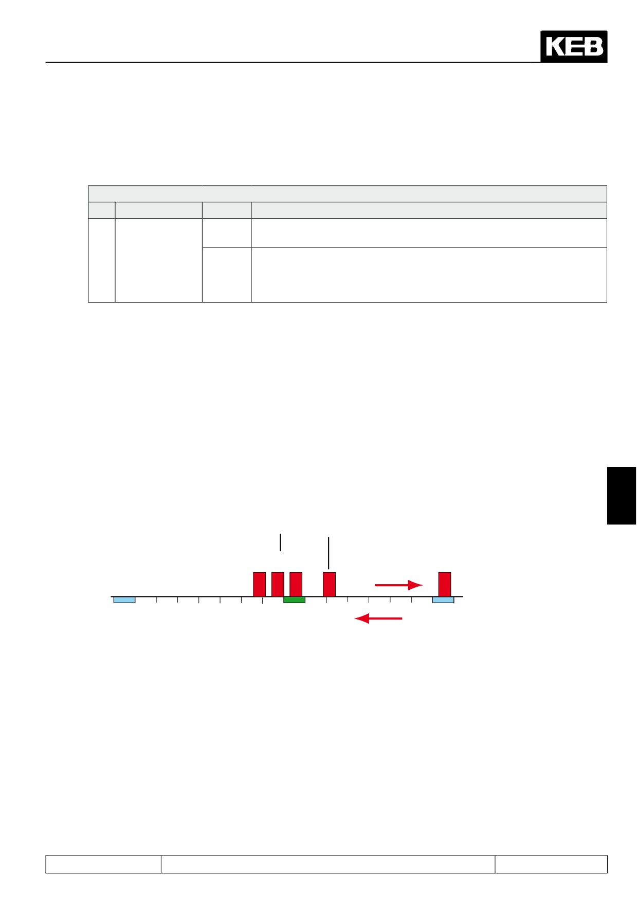
When the drive reaches the hardware limit switch for the direction of rotation, it automatically reverses and
begins searching the reference point in the
other direction of rotation.
If no reference point switch is found, the drive continuously shuttles between the two hardware limit switches.
Note: During the approach to reference point, the limit switch function works differently than in usual operation.
If the value "6: function turned off" is programmed in Pn.07 "Proh. rotation stopping mode", the drive reverses
with the acceleration and deceleration times defined in parameter PS.20 "reference acc/dec time".
For all other value of Pn.07, the setpoint speed without ramp is set to zero. The drive stops and then accele-
rates in the other direction of rotation with the ramp from PS.20. No normal quick stop is executed, and the
quick stop parameters (Pn.60 / Pn.61 / Pn.67) have no function.
7
Approach to
ref. point com-
pleted
Start
PS.21: Approach to ref. point
3/4
6/7
5
2
Speed = positive
1
0
1000
2000
3000
4000
5000
6000
7000
8000
Limit switch left
Ref. point
2
Limit switch
switch
right
Reversal after reaching the
right limit switch
Page7.12 - 9
Positioning and Synchronous Control
1
2
3
4
5
6
7
ru.02: Ramp
output display
ru.54: Actual
position
Limit switch
right
Approach to ref.
point completed
Target window
reached
Ref. point
switch
Start approach
to ref. point
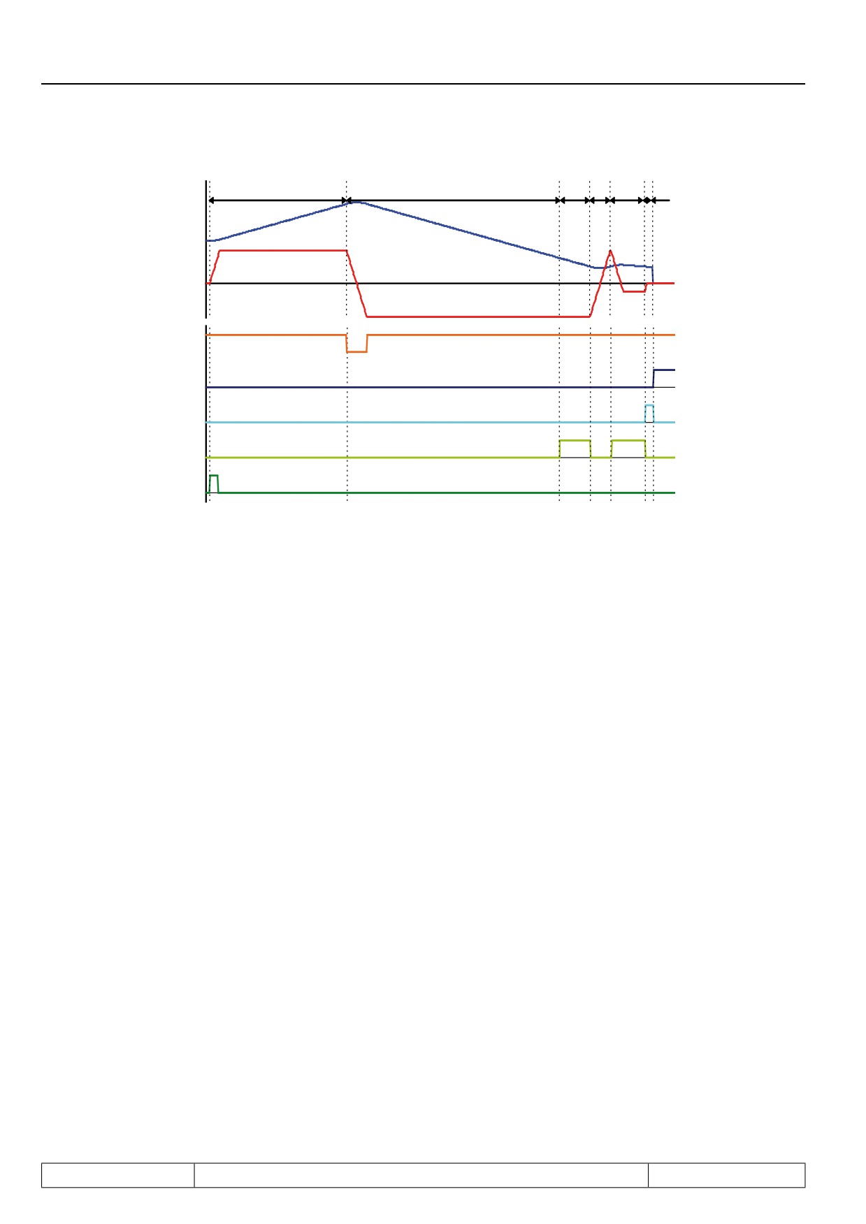
1. PS.21 positive
Drive accelerates with ramp from PS.20 and seeks in clockwise direction of rotation for the reference
switch
2. Run-on to the limit switch
Reverse and seek in the other direction of rotation
3. Overdriving of the reference switch
(because stopping the drive left of the reference switch is chosen in PS.14, the switch must be hit from
the right)
4. Reversing and running onto the reference switch in direction of rotation clockwise
5. Reversing on the reference switch and driving free at free drive-speed (PS.21/ PS.22)
6. Stopping of the drive with the ramp from PS.20
Setting of the signal "target window reached"
Wait for the damping period of 100ms
7. Overwrite the current actual position (ru.54) with the reference point position(PS.17)
Resetting of the signal "target window reached"
Setting of the signal "approach to reference point completed"
Stopping of the drive left of the reference point (programmable via PS.14)
Page7.12 - 10
Positioning and Synchronous Control
7.12.2.6
Reference point / manual setting
7.12.2.6.1
Over PS.14
If no reference point switch is provided in the application, the drive can also be manually referenced:
PS.14 Mode of position reference
Bit
Meaning
Value
Explanation
0: off
No manual setting
The drive is approached in inching mode to reference point and then "ma-
nual setting = on" (bit 6) is set. The reference point position (PS.17) is
6
Manual setting
64: on
taken as the actual position (ru.54). The switching condition "approach to
reference point completed” (do.00...07, value 29) is set, the software limit
switch function can be used.
7.12.2.6.2
With input function "set reference point"
Independent of PS.14 "Mode of position reference" or PS.00 "position / synchronous mode", the actual position
ru.54 can be overwritten with the value of PS.17 "reference point" by setting a digital input.
To that end, an input must be selected in PS.13 "set reference point input selection".
(assignment of a digital input see chapter 7.3)
If this input set during an active positioning:
-
the inverter remembers the remaining path
-
the current position ru.54 is set to the reference point position PS.17
7
-
the inverter continues the interrupted positioning
7.12.2.7
Reference point / valid position
In order for the software limit switch function to be useable, an approach to reference point must be executed
prior to the positioning. In some cases (e.g., when using an absolute encoder), an approach to reference point
is, however, not required. By activation of bit 7 "the captured position is valid = yes", the drive is informed that
no approach to reference point is necessary.
PS.14 Mode of position reference
Bit
Meaning
Value
Explanation
0: no
Approach to reference point must be executed.
The captured
The actual position (ru.54) is declared "always valid". The switching condition
7
position is
128:
"approach to reference point completed” (do.00...07, value 29) is set, the soft-
valid
yes
ware limit switch function can be used.
Page7.12 - 11
Positioning and Synchronous Control
7.12.2.8
Approach to reference point / stop at index 0
By setting bit 5 (stop at index 0 = 32: on), it can be programmed that the drive automatically (i.e., without a "boot
positioning" signal) moves to the position from index 0 after completing the approach to reference point.
PS.20 "reference acc/dec time" specifies the acceleration / deceleration values for the positioning to index 0.
The maximum profile speed for positioning is determined for Index 0 by the value of PS.25 "index speed".
The drive remains at that Position. The setting "continue profile = yes” from index 0 is ignored.
PS.14 Mode of position reference
Bit
Meaning
Value
Explanation
0: off
After approach to reference point the drive stops at the reference point.
5
Stop at index 0
32: on
after approach to reference point, the position from Index 0 is driven to.
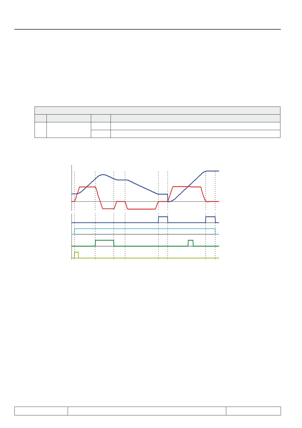
The following figure shows an approach to reference point with stop at the null signal left of the reference point
switch and automatic positioning to index 0:
1
2
3
4
5
6
7
8
ru.02: Ramp
outp. display
ru.54: Actual
position
Active approa-
che to ref. point
Target window
reached
Ref. point
switch
Start approache
to ref. point
1:
Start of approach to reference point
2.:
Run-on at the reference point switch
2 - 3: Reversing and free driving of the reference switch
3 - 4: Stop left of the reference switch
4:
Start of the positioning to the null signal of the encoder
5 - 6: Waiting out the damping period after reaching the null signal
6:
Referencing of the actual position: ru.54 is overwritten with the value of PS.17 "reference point"
6 - 7: Positioning to the target position of index 0 with the ramp time from parameter PS.20
7:
Reaching of the target position
8:
Approach to reference point finished
Page7.12 - 12
Positioning and Synchronous Control
7.12.3Synchronous mode
7.12.3.1
Synchronous mode / principle
The synchronous module realises an angle / speed synchronous control of a master drive (control drive) to one
or more slave drives. The control drive must not be closed-loop.
The master position is passed on to the slave. The master must therefore be equipped with an encoder inter-
face with incremental encoder output, and every slave with a second incremental encoder input.
Alternatively, the master can also be operated uncontrolled and the encoder signals of the master drive can be
connected directly to the slave.
The speed ratios are adjustable individually. The gear ratio is adjusted via the numerator / denominator ratio. If
the directions of rotation have to be different, a negative gear ratio has to be set.
For activated position controller, the slave is driven angular-synchronous, for deactivated position controller
(PS.06 = 0), speed-synchronous to the master drive.
The synchronous module contains other variants for synchronising (constant acceleration ramp or constant
synchronisation path) and a programmable angle correction.
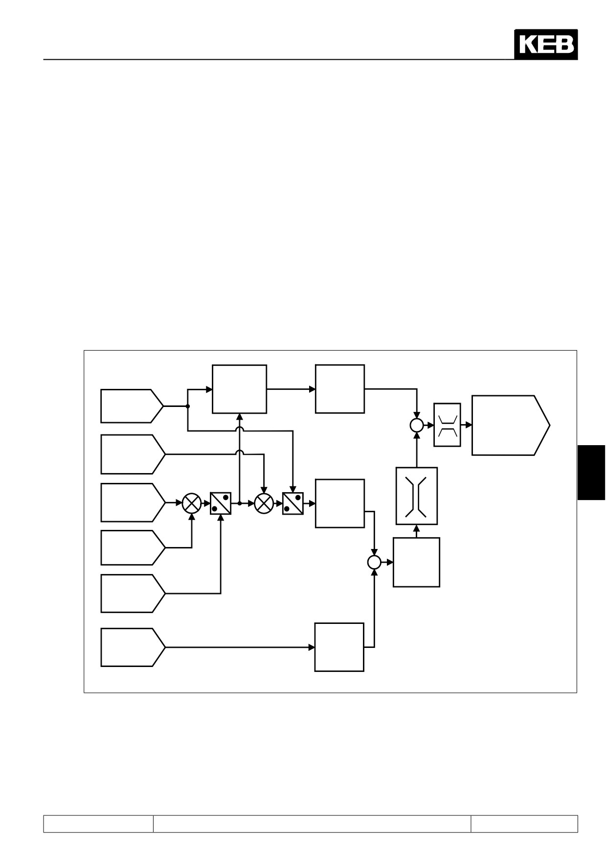
The following mapping shows the general behaviour of synchronous control (without synchronisation pha-
ses):
oP.14/oP.15
ru.10
absolute
speed
Encoder 2
maximum
calculation
Ec.11
speed
ref. for / rev
Encoder 2
ru.02
(inc/r)
+
Ramp output
display
(setpoint speed for
Ec.01
+
speed controller)
encoder 1
(inc/r)
7
PS.09
Increments
Posi/synchronous
ru.56
of encoder
position limit
Set position
channel 2
Ec.14
Gear 2 nume-
+
PS.06 to
rator
PS.08
Position
Ec.15
-
controller
Gear factor
2 denominator
Increments
ru.54
of encoder
Actual
channel 1
position
Page7.12 - 13
Positioning and Synchronous Control
7.12.3.2
Synchronous mode / premise
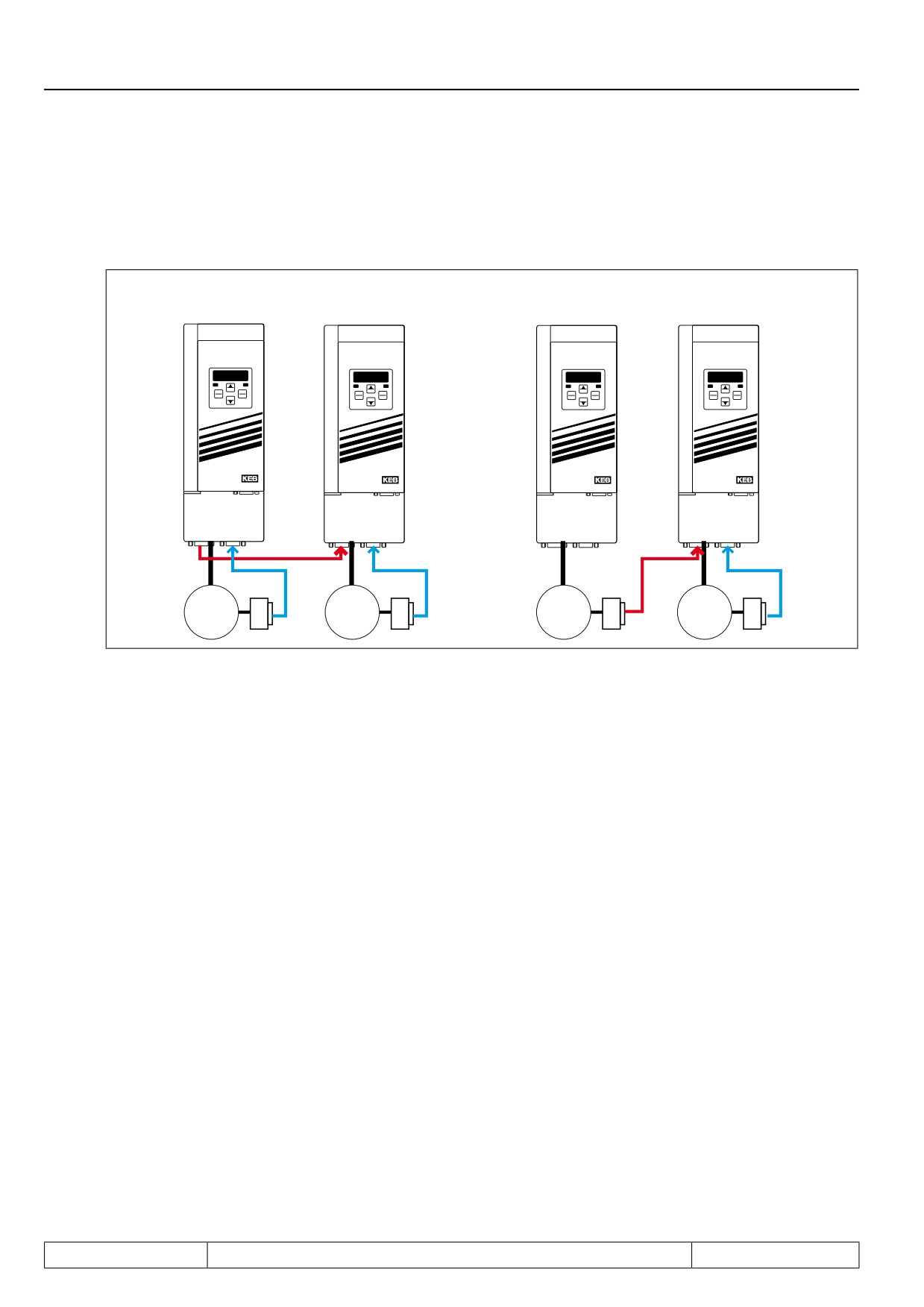
For the synchronous module, the incremental signals from the encoder of the master drive must be passed on
to the slave.
Speed con-
Speed con-
Controlled
Speed con-
trolled master
trolled slave
master drive
trolled slave
drive
drive
drive
ENTER
START
FUNC.
ENTER
START
FUNC.
ENTER
START
FUNC.
ENTER
START
FUNC.
F/R
SPEED
F/R
SPEED
F/R
SPEED
F/R
SPEED
STOP
STOP
STOP
STOP
ANTRIEBSTECHNI K
ANTRIEBSTECHNI K
ANTRIEBSTECHNI K
ANTRIEBSTECHNI K
X3B X3A
X3B X3A
X3B X3A
3
3
3
3
~
~
~
~
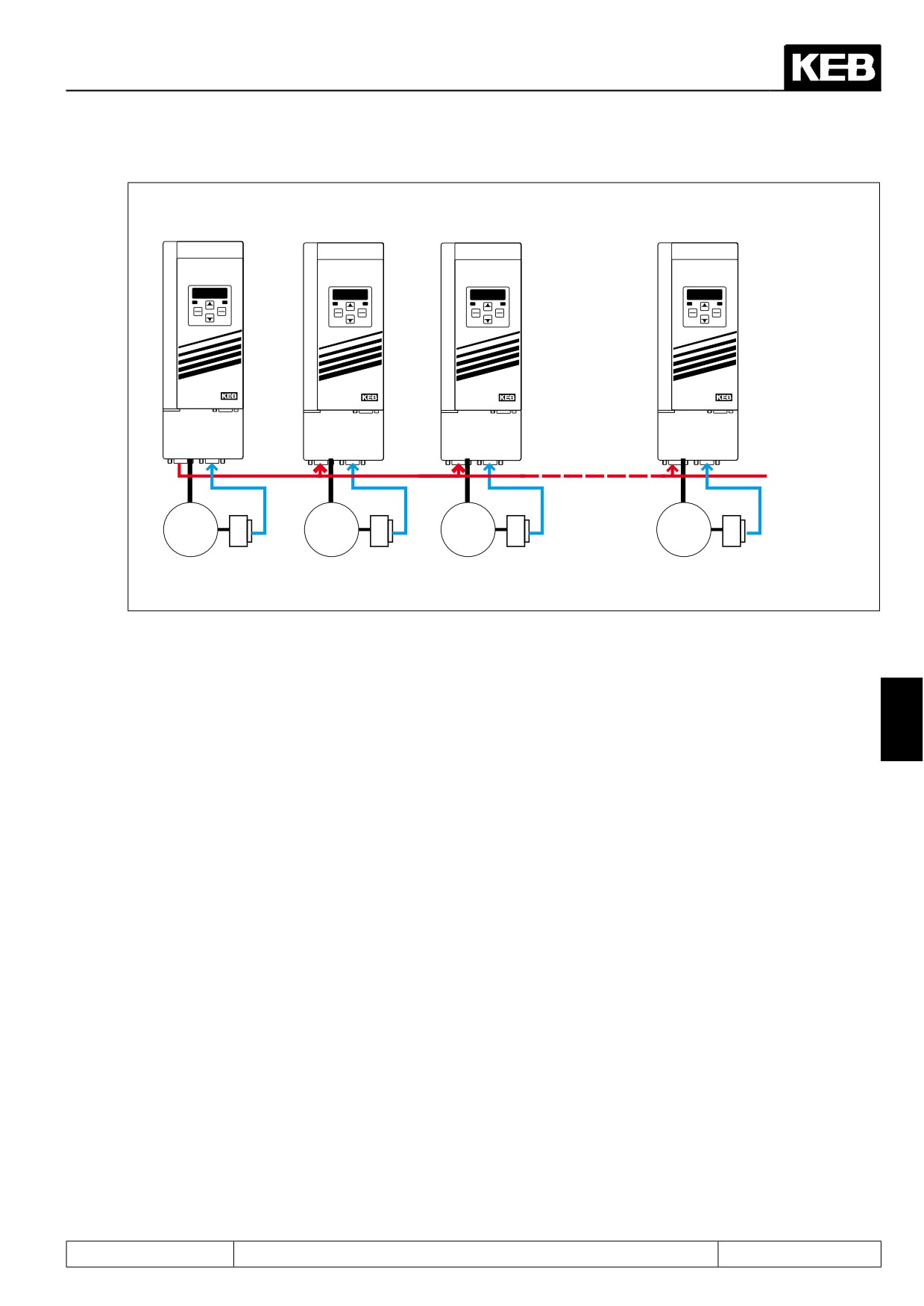
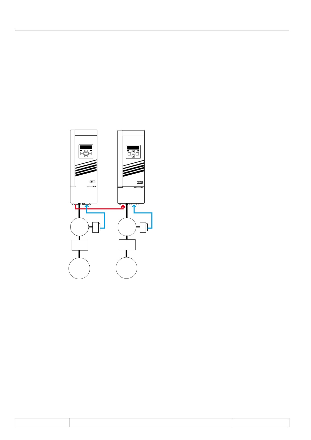
If more than one slave is connected, there are two different variations for assembling the master-slave-chain:
direct transfer of the signals from the output of the master encoder interface to all slaves.
Page7.12 - 14
Positioning and Synchronous Control
Speed con-
Speed con-
Speed contolled
Speed con-
trolled slave
trolled
master drive
trolled
drive 2
slave drive X
slave drive 1
ENTER
START
FUNC.
ENTER
START
FUNC.
START
ENTER
START
FUNC.
F/R
SPEED
F/R
SPEED
ENTERF/R
FUNC.SPEED
F/R
SPEED
STOP
STOP
STOP
STOP
ANTRIEBSTECHNI K
ANTRIEBSTECHNI K
ANTRIEBSTECHNI K
ANTRIEBSTECHNI K
X3B X3A
X3B X3A
X3B X3A
3
3
3
3
~
~
~
~
Ec.20 Encoder operating mode = 1
Ec.20 Encoder operating mode = 0
(Input + without terminating resistor)
(Input + with terminating resistor)
Disadvantages:
-
Limitation of the number (max. 10, after RS.422 specification)
-
No guarantee of an EMC conform installation (adapter required for distribution, no off-the-shelf cables
available), therefore, the second variant is preferable:
7
Advantages:
-
The incremental signals are processed. Thus, no limitation of the number of the connected slaves
-
off-the-shelf cables available that guarantee EMC compliant assembly. Further information on available
components can be found at wow.keb.de => Service & Downloads
-
Error control for processed master signal integrated in repeater
Page7.12 - 15
Positioning and Synchronous Control
7.12.3.4
Synchronous mode / position normalisation
Via parameter PS.01 act. master source, the channel from which the slave receives the master position is
selected.
This must be encoder channel 2 for most applications. (Off-the-shelf cables and a terminating resistor that can
be switched off exist only for channel 2 ).
Figure 7.12.3.4 Position normalisation
Speed con-
Speed con-
The adjoining figure shows a typical
trolled master
trolled slave
synchronous application.
drive
drive
If the load of the master drive has travelled
one
revolution, the load of the slave should also
have travelled one revolution (in the oppo-
ENTER
START
FUNC.
ENTER
START
FUNC.
F/R
STOP
SPEED
F/R
STOP
SPEED
site direction).
This is the case for, e.g., printing presses
or
rolling machines.
ANTRIEBSTECHNI K
ANTRIEBSTECHNI K
X3B X3A
X3B X3A
3
3
~
~
i= 5,25
i= 15
Load
Load
Direction of ro-
Direction of ro-
tation clockwise
tation counter-
clockwise
In parameter ru.54 "actual position", the slave position (i.e., the number of increments from the slave motor) is
displayed. In ru.54, one revolution of the slave load corresponds to:
Ec.01 "encoder 1 (inc/r)" x gear factor slave
The master position is displayed in parameter ru.56 "set position". The display occurs in increments and is
converted to the slave position. The conversion takes into account the ratio of the increments per revolution of
the encoder and the relation of the two gear factors. If the master is connected to encoder channel 2, the gear
factor of the slave must be entered in parameter Ec.14 "gear 2 numerator" and the gear factor of the master
must be entered in parameter Ec.15 "gear 2 denominator" for the conversion of the gear ratios.
Page7.12 - 16

Positioning and Synchronous Control
Since only integer values can be set, the gear factors must be expanded correspondingly
(15 : 5,25 becomes 1500 : 525).
Display in ru.56 (master position converted to slave units):
Ec.01
Ec.14 (gear factor slave)
number increments master x
———
x
———————————————
Ec.11
Ec.15 (gear factor master)
An inversion of the rotation direction of the slave compared to the master drive is achieved by setting a negative
value for Ec.14.
Example (adjustments for figure 7.12.3.3 position normalisation):
"Normal" vector controlled operation is programmed in the master, the synchronous module is not activated.
For the slave, encoder channel 1 serves as speed feedback and encoder channel 2 as master position infor-
mation. Both load shall be moved angular-synchronous, but in opposite direction of rotation.
Adjustment in the slave:
-
PS.00 "Posi / synchronous mode" = synchronous mode
-
CS.01 "Actual source" = channel 1
-
PS.01 "Actual master source" = channel 2
-
PS.06 "KP for positioning / synchronous" ≠ 0
-
Ec.14 "Gear 2 numerator" = -1500
-
Ec.15 "Gear 2 denominator" = 525
7
Typically, an approach to reference point is executed for the slave drive before the start of the synchronous
running, to create the relation between the position display of the slave drive and the mechanics of the appli-
cation.
The relation between master and slave position is created only with the activation of the synchronous module.
At the time of activation, the master position (= ru.56 "set position") is set equal to the slave position (= ru.54
"actual position").
7.12.3.5
Synchronous mode / selection of operating mode
The operating mode synchronous mode is selected via parameters PS.00 bit 0...3 or via the control word (Sy.43
or Sy.50)
PS.00: Posi / synchronous mode
Bit
Meaning
Value
Explanation
0: off
no special operation selected
1:
Synchronous
Selection of operating mode "synchronous mode"
mode
Posi / synchro-
0..3
2...6
Without function for synchronous mode
nous mode
The operating modes (synchronous running, positioning mode
7: Via control word
or contouring control) are selected via the control word (Sy.43
or Sy.50).
Page7.12 - 17
Positioning and Synchronous Control
If PS.00 bit 0..3 contains the value 7:
Sy.50: control word (low) / Sy.43: control word (long)
Bit
Meaning
Value
Explanation
0: off
4096: Synchro-
Selection of operating mode synchronous running
Operating
nous running
12/13
mode
8192: Positioning
Selection of operating mode positioning
12288: Contou-
Selection of operating mode contouring control
ring control
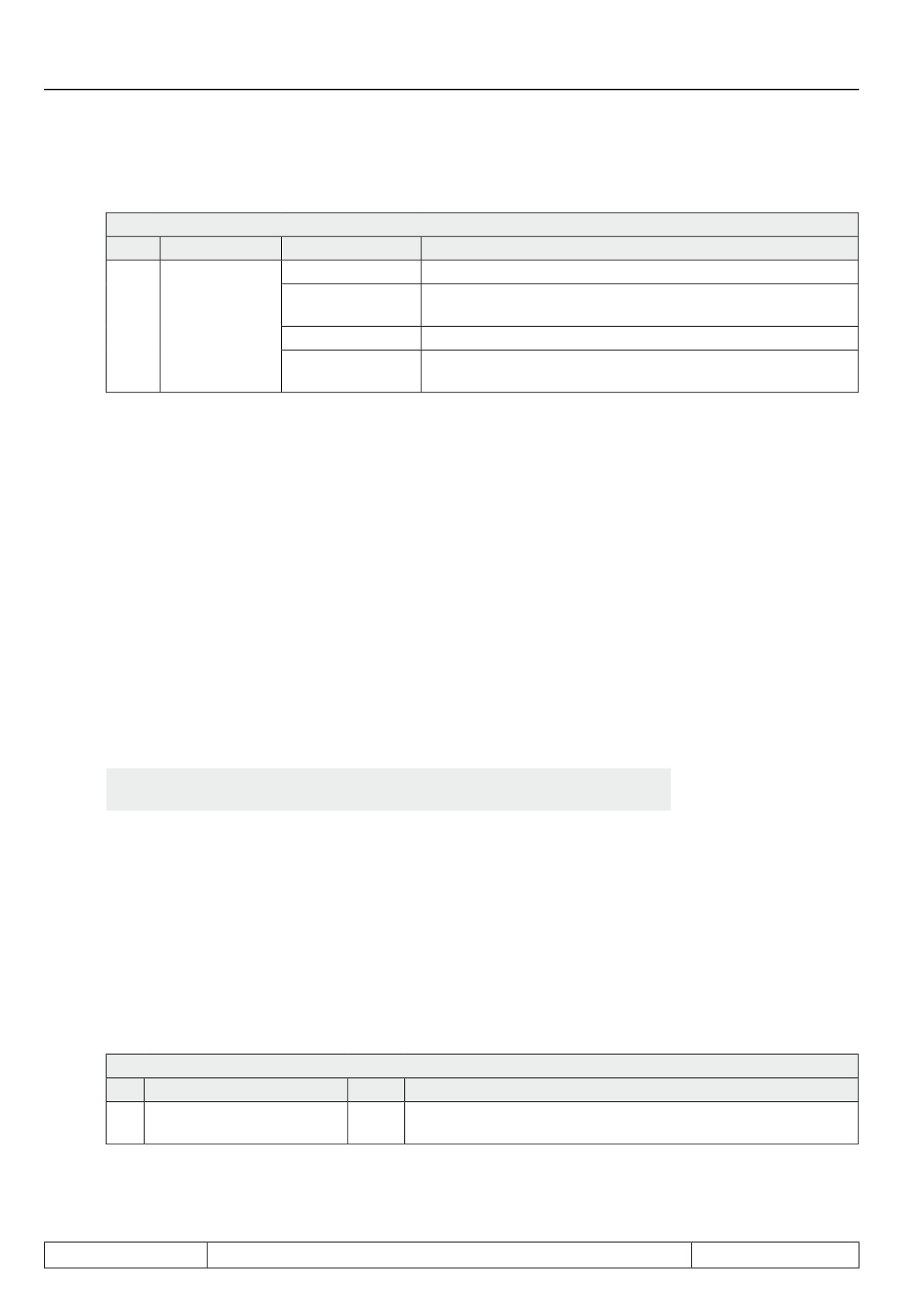
PS.00 can only be written if the modulation is switched off, Sy.50 can always be written. The synchronous mo-
dule must be activated by an input. Which input is to be used is determined via parameter PS.02 "posi / sync
input selection".
7.12.3.6
Synchronous mode / activation and synchronization
7.12.3.6.1
Principle
With the activation of the synchronous module, the relation between master position and slave position is es-
tablished.
Activation means:
-
Synchronous mode is selected in parameter PS.00,
-
Modulation is enabled,
-
the digital input for activation of the synchronous operation is set.
At the time of activation, the starting synchronisation begins.
Gear factor changes, angle correction or similar may not be execut-
Attention:
ed during the synchronisation.
The synchronous module is not deactivated by switching of the modulation. The angle difference is continuous-
ly calculated, and, after again switching on the modulation, a synchronisation with ramps is always carried out
(independent of the type of initial synchronisation).
The type of the synchronisation at activation of the synchronous running is determined by the setting of "acce-
leration time forward (oP.28)" in parameter PS.00 "position / synchronous mode" and by the parameter PS.05
"start offset" .
7.12.3.6.2
Synchronization at limit
For synchronisation at the torque limit, the starting ramp must be deactivated.
PS.00: Posi / synchronous mode
Bit
Meaning
Value
Explanation
Synchronous running / star-
No starting ramp for synchronisation at the start of the synchro-
10
0: off
ting ramp (oP.28)
nous running.
Furthermore, the value 0 must be set in parameter PS.05 "start offset".
Page7.12 - 18
Positioning and Synchronous Control
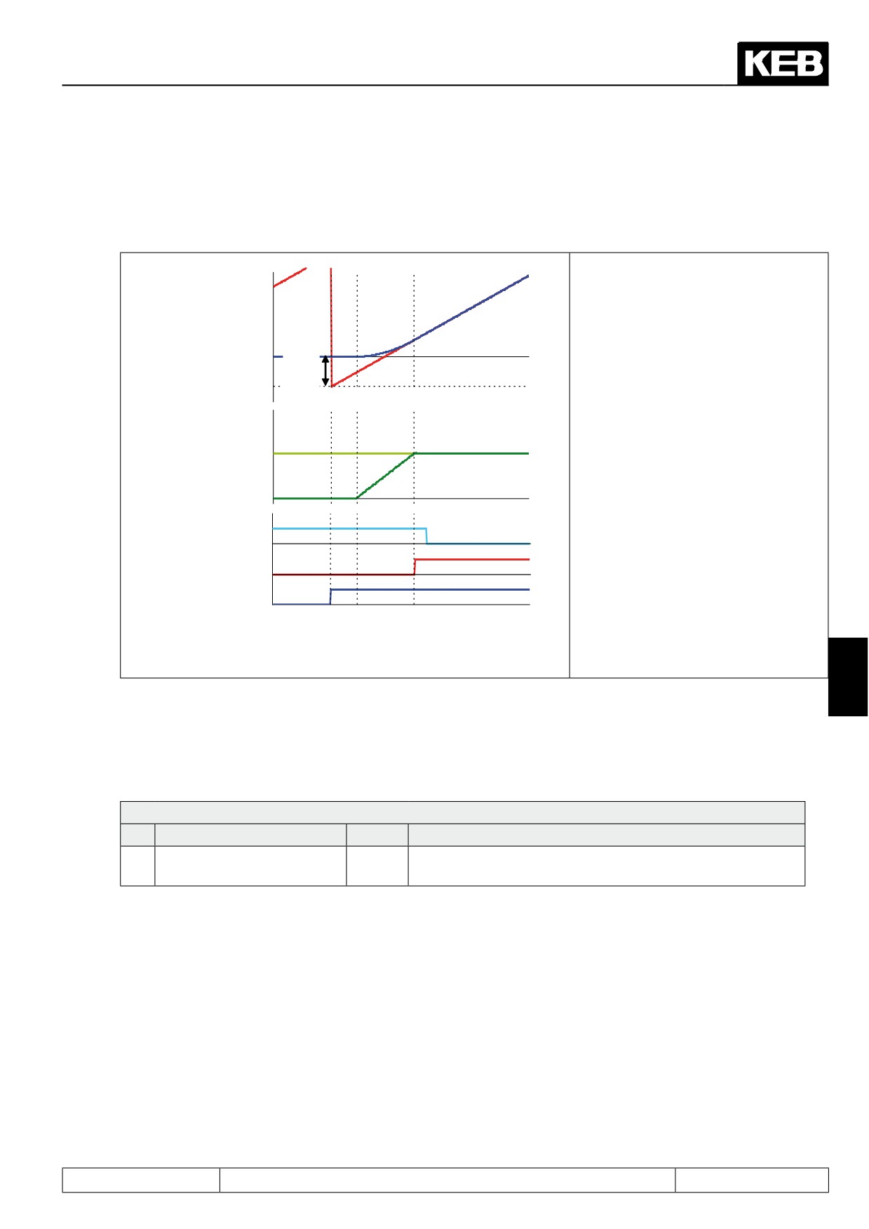
This parametrisation is only reasonable if master and slave rotate at the same speed at the start of the syn-
chronous operation, so that a synchronisation is unnecessary. If the speeds are different, the synchronisation
occurs in the following manner:
At activation of the synchronous mo-
ru.56: Set position
dule, the set point position is set to the
(master position)
actual position.
ru.54: Actual positi-
The setpoint speed of the slave is set
on (slave position)
PS.05:
Start-
to the actual speed of the master.
offset
The difference to the master position is
corrected by the position controller.
Maximum speed of the slave:
Actual speed
master
(converted with
Master speed + PS.09
gear ratio)
The switching condition "drive running
Act. speed slave
synchronously" is met with activation
Angle difference >
of the synchronous mode.
level
Drive runs synchro-
To recognize the instant at which both
nous
drives are actually running synchro-
Activate posi/ syn-
nously, the switching condition "angle
chronous running
Time
difference < level" must be linked with
the signal "drive running synchronous-
ly".
7
7.12.3.6.3
Synchronization with constant path
For the synchronisation within a constant path, the starting ramp must be deactivated.
PS.00: Posi / synchronous mode
Bit
Meaning
Value
Explanation
Synchronous running / star-
No starting ramp for synchronisation at the start of the syn-
10
0: off
ting ramp (oP.28)
chronous running.
The path which the master traverses during the synchronisation is entered in parameter PS.05 "starting offset".
The slave drive calculates internally the acceleration / deceleration times with which it reaches the master
speed within the adjusted path. If the master has traversed the programmed path, the master position is set to
the slave position.
Example:
Let the master speed be 1500 rpm. Let the encoder type be an incremental encoder with 2500 pulses. Let
"multiple evaluations" be set to the value "2:4-fold".
This results in 10000 increments / revolution * 1500 U / 60s = 250000 increments/ s
Page7.12 - 19
Positioning and Synchronous Control
If the value 250000 increments is set in PS.05, the slave must also accelerate to the master speed
in 1s. The disadvantages of this type of initial synchronization are as follows:
-
The synchronisation path is set via parameter PS.05 "start offset", making it difficult to realise an
offset between master and slave at the start.
-
Checking whether the synchronisation was successful is not possible. If the slave drive cannot fol-
low the calculated ramp (e.g., due to reaching the torque limit), the master position is still set to the
slave position. The angle synchronicity is lost thereby (For the example above, the connection to the
position of the switch "activate synchronous running" would be lost). The switching condition "drive
running synchronously" is also still set in spite of the angle error.
-
Even if the slave drive can generally follow, system deviations can distort the accuracy of the angle-
synchronous running.
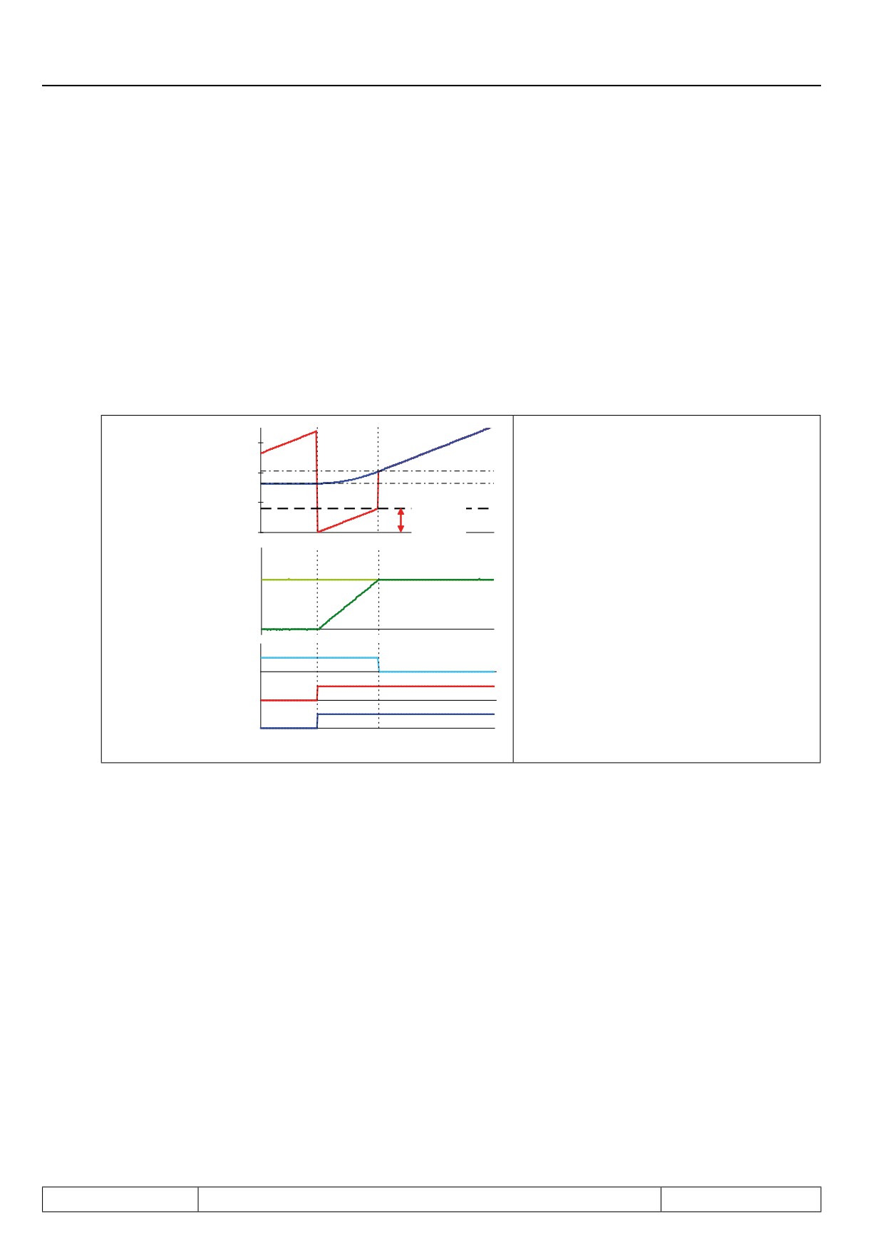
At the activation of the synchronous module,
ru.56: Set position
3000
the master position (set point position) is set
(master position)
to 0.
2000
ru.54: Act. position
When the master has completed the path
(slave position)
1000
programmed in PS.05, the master position is
PS.05:
set to the slave position.
Startoffset
0
Actual speed
master
The slave drive calculates the acceleration /
(converted with
deceleration ramps it needs to reach the ma-
gear ratio)
ster in this time.
The ramp time also depends on the master
Act. speed slave
speed and the value in PS.05.
After the master has completed the path
Angle difference >
level
PS.05, the master position (set point position)
is overwritten with the slave position (actual
Drive runs synchro-
position).
nous
Activate posi/ syn-
chronous running
Time
Page7.12 - 20
Positioning and Synchronous Control
7.12.3.6.4
Synchronization with ramp
The synchronisation with ramp is the most comfortable method for the initial synchronization. It is always used
for
synchronisation after interruption of the synchronous running due to switching off the modulation.
PS.00: Posi / synchronous mode
Bit
Meaning
Value
Explanation
Synchronisation at the start of the synchronous running with
Synchronous running /
10
1024: off
the ramp times for acceleration / deceleration, clockwise ro-
starting ramp (oP.28)
tation
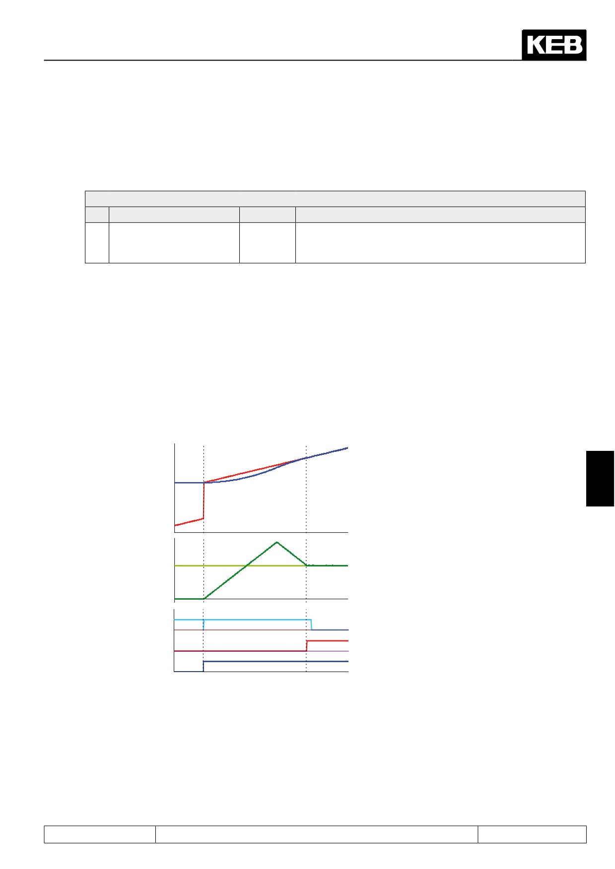
With activation of the synchronous module, the master position (set position ru.56) is set to the slave position
(actual position ru.54).
The slave accelerates with the predefined ramps, to follow the master.
Because of the differing speeds of master and slave, an angle difference occurs. This missing distance to re-
aching the master position is made up for by increasing the slave speed beyond the master speed. The slave
calculates a setpoint speed profile, which allows it to make up for the angle difference.
Maximum speed for this setpoint profile is the maximum reference oP.10 / oP.11. If the drive cannot follow the
setpoint speed profile, the remaining angle difference is eliminated by the position controller. Therefore, the
maximum speed during the synchronisation phase is oP.10 / oP.11 + position controller limit PS.09. This value
is still limited by the absolute maximum reference (oP.14 / oP.15).
At the start of the synchronous running, the ma-
ster position (set position ru.56) is set to the sla-
ve position (actual position ru.54).
ru.54: Act. position
(slave position)
The slave accelerates and makes up for the lost
7
distance.
The ramps must be adjusted so that the slave
ru.56: Set position
drive can follow without reaching the torque li-
(master position)
mits.
Actual speed
The switching condition "drive running synchro-
master
nously" is set if the calculated setpoint speed
(converted with
profile for reaching the master position is com-
gear ratio)
pleted.
Act. speed slave
If, e.g., the torque limit is reached, angle syn-
chronicity is not given at that time.
Angle difference >
If achievement of a specific angle accuracy has
level
to be checked, the switching condition "drive run-
Drive runs synchro-
ning synchronously" must be linked with the swit-
nous
ching condition "angle difference < level".
Activate posi/ Syn-
chronous running
Time
As soon as the slave reaches the last phase of the synchronisation
(that means: the last deceleration and
acceleration to the master speed, respectively) the ramp can deviate from the programmed values. This is the
case if the master speed is not constant, i.e., if adjustments still have to be made during the running-in. Adjust-
ments of the value for acceleration or deceleration are not accepted anymore during this phase.
Additionally, an offset can be entered in parameter PS.05 "start offset" to run the master offset to the slave . The
master position is set to the value slave position - PS.05 upon activation of the synchronous running.
That means: ru.56 = ru.54 - PS.05 (at the time of activation)
Page7.12 - 21
Positioning and Synchronous Control
1 = Material holder (master)
2 = Tool holder (slave)
Incremental encoder
Incremental encoder
1024 Increments per revolution
2500 Increments per revolution
10 cm according to one motor revolution
10 cm according to one motor revolution
Switch to acti-
Switch to deac-
vate synchro-
tivate synchro-
nous running
nous runnning
Activation of the
synchronous
1
cm
running
0
10
2
30
40
50
60
70
80
Start of action
(drilling)
1
cm
2
0
10
20
30
40
60
70
80
End of action
1
(drilling)
cm
0
10
20
30
40
50
2
70
80
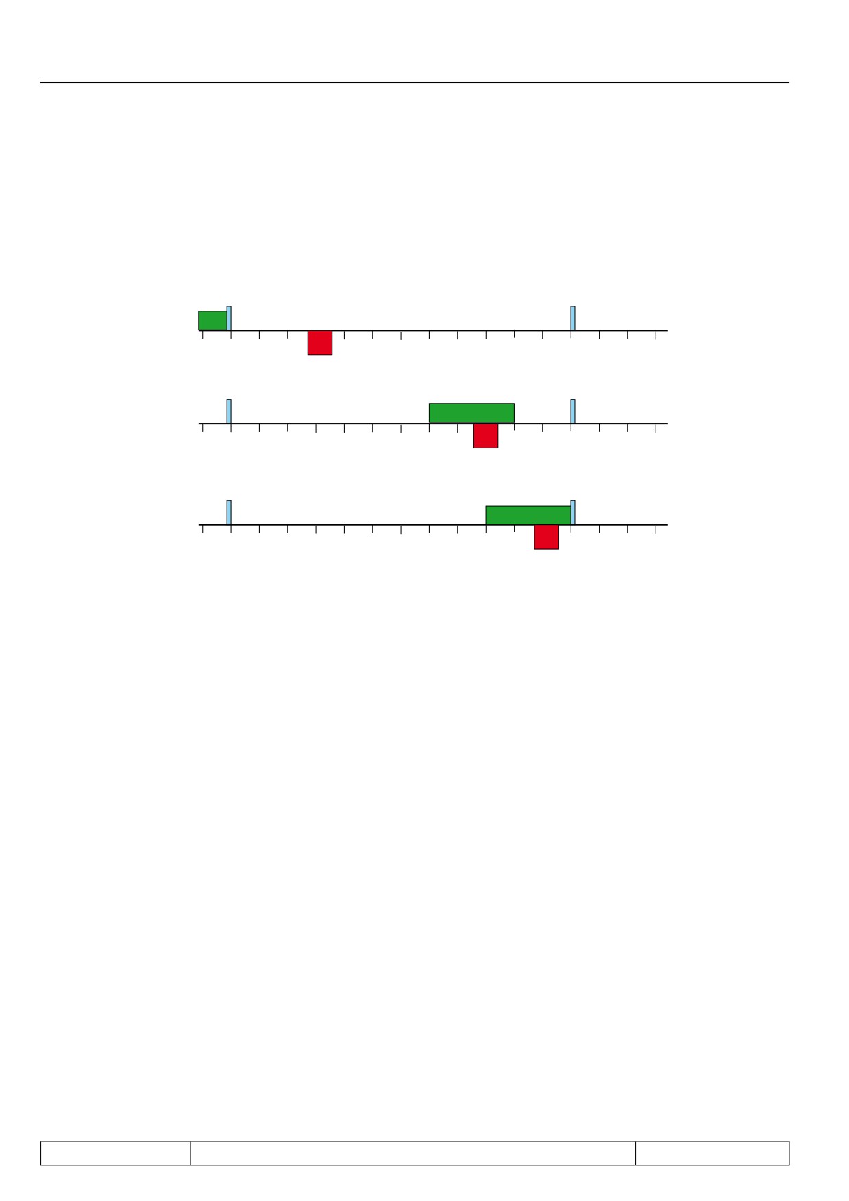
The master drive is a material carrier (e.g., a conveyor belt), on which materials (e.g., boards) are transported
at variable speed.
The leading edge of the material crosses an indicator and thereby activates the synchronous running of the
slave drive.
The slave is a tool carrier (transporting, e.g., a drill drive). As long as there is no board, it remains at a defined
resting position (20 cm).
The hole should be drilled 5cm from the front edge while the conveyor is running.
The slave must run absolutely angular-synchronously to the master during the drilling.
When the board reaches the 2. switch, the drilling process must be safely concluded. The synchronous running
is deactivated and the slave can now (e.g., in positioning operation) run back to the starting position.
From the activation of the synchronous running to the start of the drilling, the master must travel 50cm and the
slave 30cm.
In parameter PS.05 "start offset", therefore, an offset of 20cm, converted to increments, must be entered.
For the example
-
10cm = 3 motor rotations => 20cm = 6 motor rotations
above:
-
2500 encoder / 4-fold evaluation => 10000 increments per revolution
-
PS.05 = 6 * 10000 = 60000 increments
During the phase of acceleration to the master speed, the slave travels at the average speed:
initial speed, slave + (master speed - initial speed, slave)
————————————————————————————
2
In our example:
let the real master speed be 500 rpm
the master needs 1 motor revolution for 10cm, the slave 3 motor revolutions
=> Ec.14 = 3000 / Ec.15 = 1000
Page7.12 - 22
Positioning and Synchronous Control
The master speed converted to the slave standardisation is therefore 1500 rpm.
The slave speed at the start is zero. Let the acceleration time be 0.2s (per 1000 rpm).
For the acceleration from 0 to 1500 rpm the slave therefore needs 0.3s. The mean speed in the acceleration
phase is 750 rpm = 12.5 U/s. Each revolution corresponds to 10,000 increments.
This results in an acceleration path of:
12,5 U/s x 10000 increments / U x 0,3s = 37500 increments
The master (converted to slave standardisation) constantly runs at 1500 rpm = 75000 increments in 0.3s. The
difference between master and slave is 37500 increments. PS.05 is 60000 increments.
The slave must therefore wait until the master has travelled another 22500 increments and then synchronises
itself without overshooting according to the adjusted ramp.
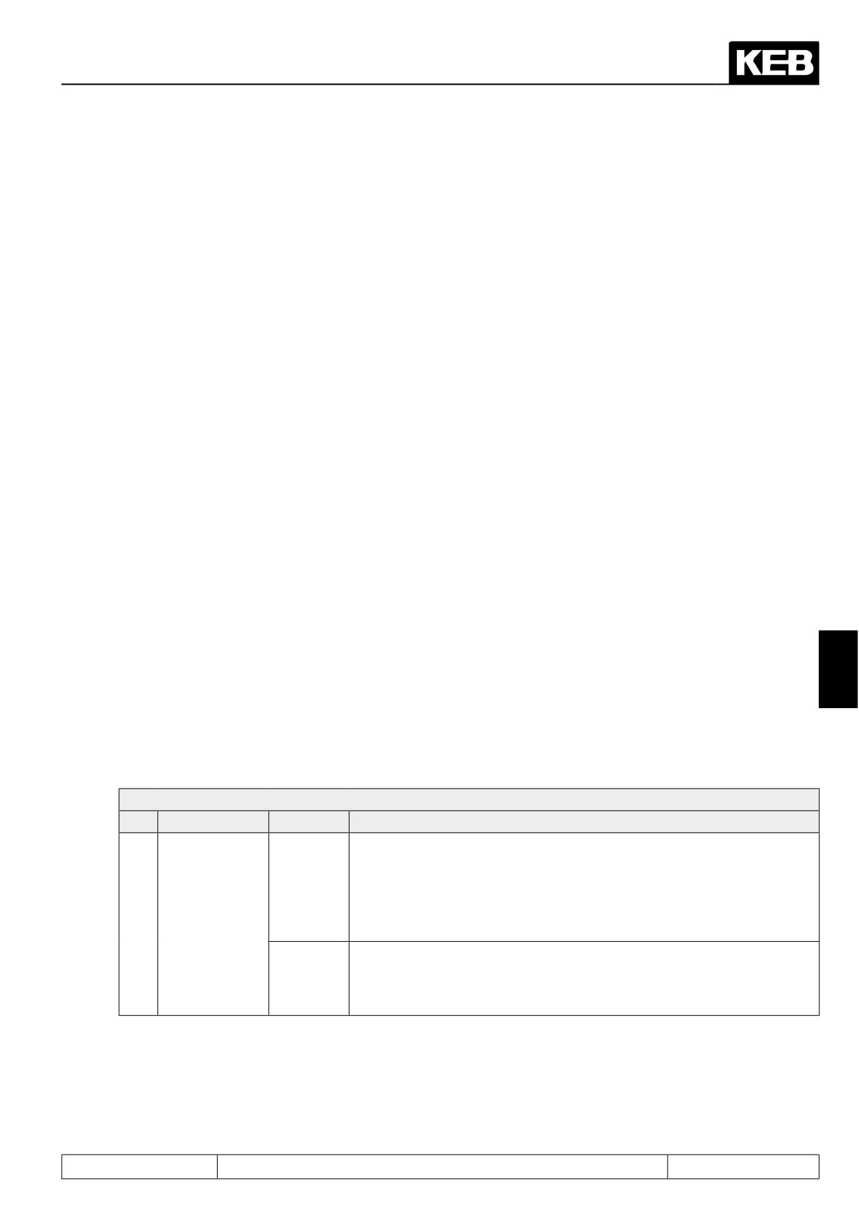
Master and slave are running at the correct offset angle after 37500 increments = 3.75 revolution = 12.5 cm of
the slave. They are, therefore, synchronous starting at the drill head position 32.5cm.
7.12.3.7
Gear factor
The gear factor between master and slave is entered in the parameters for the encoder channel connected to
the master position. Normally, this is encoder channel 2. Therefore, the gear factor must be entered in Ec.14
(or Ec.58, respectively) "gear 2 numerator" (= gear factor of the slave) and Ec.15 (or Ec.59, respectively) "gear
2 denominator" (= gear factor of the master).
The gear factor is not set-programmable. If it is to be adjusted set-dependently, this can be implemented by
appropriately setting the analog parameters (see chapter 7.15.9). As the source, the value "1: motor potentio-
meter" must be chosen in An.53. The motor potentiometer value (oP.52) is set-programmable.
Control by means of an analog channel is also possible via the analog parameter settings.
7
The new gear factor during the active synchronous operation changes (at equal actual speed of the master
drive) the master speed expressed in the scale of the slave. Due to the now different
speeds of master and slave, an angular offset is created and the slave must be synchronised again:
PS.00: Posi / synchronous mode
Bit
Meaning
Value
Explanation
The slave carries out the new synchronisation using the acceleration /de-
celeration times for clockwise rotation. The sequence corresponds to the
initial synchronisation with ramps (see instructions in item 7.12.3.5.4),
0: on
Synchronous
only that the parameter PS.05 "start offset" has no effect. The treatment
running / gear
of the switching condition "drive running synchronously" corresponds to
11
factor ramp
the behaviour during initial synchronisation with ramps.
(oP.28)
The slave carries out the synchronisation without ramps at the speed /
torque limit. This setting can be useful if the gear factor is changed con-
2048: off
tinuously via the analog channel. The switching condition "drive running
synchronously" remains set.
If the gear factor change is smaller than 0.5%, the change is applied without ramp.
Page7.12 - 23