KEB COMBIVERT F5-A,-E,-H 4.0. APPLICATION MANUAL (2008) - page 14

Speed Measurement
7.11.7 Basic settings
Adjust increments per revolution (Ec.01, Ec.11)
With this parameter the encoder line number is adjusted to the connected encoder within a range of
1…16383.
-
Ec.01 for encoder interface 1
-
Ec.11
for encoder interface 2
Time 1 (2) for speed calculation (Ec.03, Ec.13)
This parameter defines the time over which the speed average value is determined. At that the resolution of the
speed detection is defined simultaneously:
Ec.03, Ec.13: Time 1 / 2 for speed calculation
Value
Scan time
Speed resolution when using an incremental encoder with 2500
pulses
0
0,5 ms
12 rpm
1
1 ms
6 rpm
2
2 ms
3 rpm
3
4 ms
1,5 rpm (factory setting)
4
8 ms
0,75 rpm
5
16 ms
0,375 rpm
6
32 ms
0,1875 rpm
7
64 ms
0,09375 rpm
8
128 ms
0,046875 rpm
9
256 ms
0,0234375 rpm
When using other line numbers:
Specified speed resolution x 2500
Speed resolution
=
-——————-——————-——————
Line number
Encoder 1 / 2 rotation (Ec.06, Ec.16)
A rotation change for encoder input 1 can be executed with Ec.06 bit 0...1 and for encoder input 2 with Ec.16.
A system inversion can be activated with bit 4 (value 16). With the system inversion it is possible to run the
motor counter-clockwise at the shaft with positive pre-settings without changing the hardware.
Page7.11 - 12

Speed Measurement
The following adjustments are possible:
Ec.06, Ec.16: Encoder 1 / 2 rotation
Value
Function
Direction of rotation
0
no change
1
Inverted
2
depends on the sign of the actual frequency (initiator)
3
depends on track B (initiator terminal 4)
4-15
reserved
Encoder system
0
no
16
Inverted
Encoder 1 / 2 trigger (Ec.07, Ec.17)
Value
Evaluation of the encoder signals
0
1-fold (for initiator: evaluation of positive edges only) (20)
1
2-fold (for initiator: evaluation of positive and negative edge)(21)
2
4-fold (for incremental encoder) (22) default
3
8-fold (23)
4
16-fold (24)
5
32-fold (25)
7
6
64-fold (26)
13
8192-fold (213)
Page7.11 - 13

Speed Measurement
7.11.8 Gear factor
7.11.8.1
Definition
The gear factor (ratio drive speed to output speed) is defined b 2 parameters: gear factor numerator and gear
factor denominator
Counter
Gear factor =
--------
Numerator
For every encoder channel, a gear factor can be given. Ec.04 / 05 or Ec.56 / 57 defines the gear factor for
channel 1. Ec.14 / 15 or Ec.58 / 59 defines the gear factor for channel 2.
In the second parameter pair (Ec.56 / 57 and Ec.58 / 59, respectively), the gear factor can be set with a higher
resolution and a greater value range.
Which parameter pair defines the gear factor is determined by the parameter "gear factor counter long" (Ec.56
for channel 1 respectively Ec.58 for channel 2).
If this parameter contains a value not equal to "0:off" for the respective channel, the "long" gear factors apply.
Overview of the parameters for gear factor setting:
Parameter
Description
Default
Value range
value
Ec.04
gear 1 numerator
-30000…30000
1000
Ec.05
gear 1 denominator
0...30000
1000
Ec.56
Gear 1 numerator long
-1073741824...off...1073741823
off
Ec.57
Gear 1 denominator long
0…10741823
1000
Ec.14
Gear 2 numerator
-30000…30000
1000
Ec.15
Gear 2 denominator
0...30000
1000
Ec.58
Gear 2 numerator long
-1073741824...off...1073741823
Off
Ec.59
Gear 2 denominator long
0…1073741823
1000
Setting a gear factor is necessary in the following applications:
•
Motor encoder connection via a gear
If the speed sensor for the motor speed cannot be connected directly to the motor shaft, the gear ratio
between motor and speed sensor must be set.
•
Use of a resolver with a pole-pair number greater than 1
By default, the use of resolvers with pole-pair number 1 is assumed. If other types are to be used, the
different pole-pair number is treated like a gear factor. The ratio of gear factor denominator to gear factor
numerator must be set equal to the pole-pair number. If different synchronous motor are to be used in
this set-up, it must be ascertained that the value pole-pair number x gear factor is integer (see below:
example 1).
•
Synchronous running
For synchronous control, the gear ratio between master and slave drive must be known to the inverter
(see chapter 7.12.3.3 synchronous mode / position normalisation)
•
Positioning
Page7.11 - 14
Speed Measurement
The gear factor is needed if control is not directly by motor position, but the position encoder is connected
with a gear (see chapter 7.12.4.3 position normalisation).
•
Adaption of special encoder
The maximum value for the number of increments per revolution of an encoder that can be entered in
Ec.01 or Ec.11 is 65535. The permissible maximum number of increments per revolution may be smaller
(for Sin/Cos encoders, e.g., 2048), depending on the interface type. By using the gear factor, encoders
with more increments per revolution can be used (see below: example 2). This adaption is not always
feasible and introduces limitations (e.g., no approach to reference point in response to the encoder-zero
impulse possible).
The main uses of the gear factor occur in the operating modes positioning and synchronous running. The effect
of the gear factor and the correct settings for the various mechanical set-ups are described in more detail in
chapters 7.12.3.3 and 7.12.4.3 .
Examples for the special case of encoder adaption via the gear factor are listed below:
Example 1: 3, pole-pair resolver on channel 1
Pole-pair number of the resolver = 3, pole-pair number of the synchronous motor = 3
ratio gear factor denominator to gear factor numerator must be equal to the pole-pair number
Ec.05 Gear 1 denominator = 3000
Ec.04 Gear 1 numerator = 1000
Ec.39 Encoder 1 over transmission = 1
For the operation of encoders that are not directly mounted to the motor or for operation of resolvers with a
pole-pair number > 1, the parameter Ec.39 must be set to "1: motor encoder".
7
The gear factor is 1/3, the pole-pair number of the motor = 3
Gear factor x pole-pair number of the motor = 1
=> synchronous motor can be operated in this set-up .
Example 2: Use of an encoder with too many increments per revolution
Encoder channel 1 is connected to a Sin/Cos encoder with 45000 increments.
The maximum value for Ec.01 for this interface type is 2048.
The increments per revolution are therefore split into 45000 = 1800 x 25.
The value 1800 is set as increments per revolution, the value 25 is set as gear factor.
Ec.01 Encoder (inc/r) 1 = 1800
Ec.04 Gear 1 numerator = 1
(must contain the value 1)
Ec.05 Gear 1 denominator = 25
Ec.39 Encoder 1 over transmission = "2 Ec.1 x E. 5 (1 zero impulse per revolution)"
For this special operation (splitting the real increments per revolution into gear factor denominator and incre-
ments per revolution), Ec.39 must be set to 2.
This special operation is only available for channel 1.
Page7.11 - 15
Speed Measurement
7.11.8.2
Gear factor / analog setting
The gear factor numerator (Ec.04 and Ec.14, respectively) can be changed via the analog parameter setting
(see chapter 7.15.9).
Example:
The goal is to be able to set the gear factor for encoder channel 2 to between 0.9 and 1.1.
Gear factor denominator is chosen as 1000.
The gear factor numerator must also be settable to between 900 and 1100.
The analog setting shall be done through the Aux-input
=> An.53 Analog parameter setting source = 0: Aux input (ru.53)
The target of the setting is Ec.14 gear factor channel 2 numerator (bus adress 100E hex)
=> An.54 Analog parameter setting destination = 100Eh
For an analog value of 0%, one should have gear factor numerator = 1000
=> An.55 Analog parameter setting offset = 1000
For an analog value of 100%, the gear factor numerator should be 1100
=> An.56 Analog parameter setting max. value = 1100
With this setting, a gear factor of 0.9 to 1.1 can be set with an Aux value of -100%...100%.
7.11.8.3
Gear factor / set-programming
The gear factor is generally not set-programmable.
There is a workaround in case the application needs a set-dependent gear factor.
One uses the option of analogously setting the gear factor for this purpose. As the source for the analog para-
meter setting, not an analog input but the motor potentiometer value is selected, which can be specified set-
dependently.
Example:
In set 0, the gear factor should have the value 0.5, in set 1, the value 1, and in set 2, the value 1.5. Gear factor
denominator is chosen as 1000. The gear factor numerator must therefore be: in set 0 = 500, in set 1 = 1000,
and in set 2 = 1500.
The analog setting should be done by motor potentiometer
=> An.53 Analog parameter setting source = 1: Motor potentiometer (ru.37)
Page7.11 - 16
Speed Measurement
The target of the setting is Ec.14 gear 2 numerator (bus address 100E hex)
=> An.54 Analog parameter setting destination = 100Eh
The value range is symmetrical around 1000 (+/- 500)
=> An.55 Analog parameter setting offset = 1000
The maximum value for the gear factor numerator should be 1500
=> An.56 Analog parameter setting max. value = 1500
The set-dependent gear factors are now realised through the different values for oP.52 "motor potentiometer
value". For that purpose, the following setting have to be made :
Set 0..2:
oP.53 Motor potentiometer min. value =
-100%
Set 0..2:
oP.54 Motor potentiometer max. value =
100%
Set 0:
oP.52 Motor potentiometer value =
-100%
Set 1:
oP.52 Motor potentiometer value =
0
Set 2:
oP.52 Motor potentiometer value =
100%
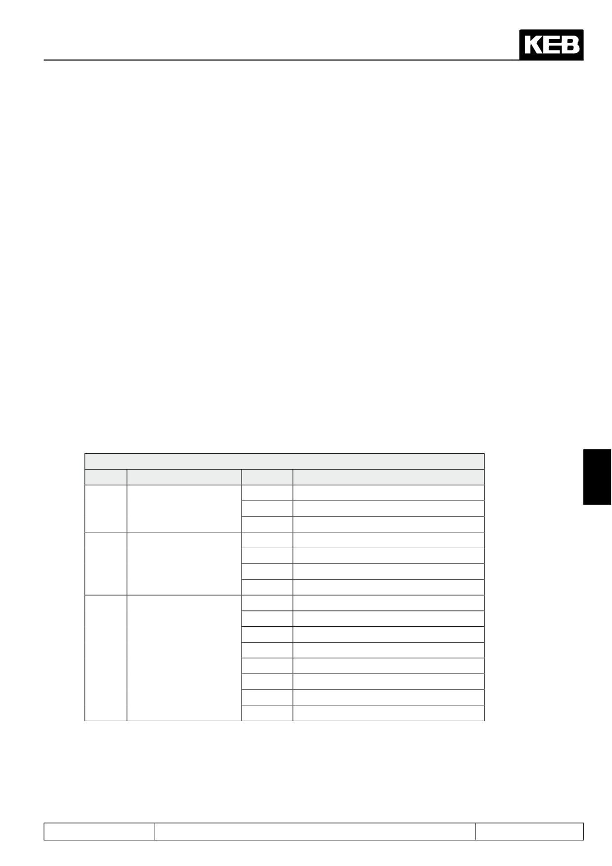
7.11.9 Operation mode output
With this function an encoder simulation can be adjusted.
Ec.27: Operation mode output
Bit
Function
Value
Description
7
0
from channel 1
Acceptance of the va-
0...1
1
from channel 2
lues
2
from actual value
0
256
Number of increments
4
512
2...3
to be output
8
1024
12
2048
0
1 (direct)
16
2
32
4
48
8
4...5
Divisor
64
16
80
32
96
64
112
128
Page7.11 - 17
Speed Measurement
Ec.27 adjusts the mode of the simulation channel. Ec.27 bit 0..1 source = channel 2 normal simulation is only
reasonable at an encoder interface with a third channel.
If the actual value (value 2) is adjusted in bit 0...1 of parameter Ec.27 the selected number of increments de-
fined with bit 2...3 is simulated.
7.11.10
Absolute position encoder 1 / 2 (Ec.02 / Ec.12) (only for F5-S)
For servo motors, the system position of the connected encoder system must be adjusted. With this parameters
it is possible to adjust the controller to a not aligned motor.If the system position of the motor is unknown an
automatic trimming can carried out.
Before starting with the adjustment, the direction of rotation must be checked. The speed display (ru.09/10)
must be positive in the case of manually clockwise rotation. If this is not the case, the direction of rotation can
be switched with Ec.06/16, as described (see chapter 7.11.7 "initial settings").
-
enter motor data / Fr.10
-
the connected motor must be able to rotate freely
-
open control release
-
enter Ec.02 / Ec.12 = 2206
-
Close control release
The motor is excited now with its rated current. If the direction of rotation of the connected motor is not correct
or two motor phases are exchanged, E.EnC is triggered.
If the system position displayed in Ec.02/12 no longer changes, the trimming is completed respectively ru.00
= 127.
-
open control release
If motors with aligned encoder systems are used, the value determined by the automatic trimming can be
entered directly in Ec.02/12.
In order to replace S4-systems by F5-S the following calculation must be carried out:
Ec.07 (S4) x pole-pair number
• The lower 16 bit of the result must be entered in Ec.02/12.
• furthermore pay attention to the encoder cable
The encoder can be adjusted to a preset system position value with Ec.40.
7.11.11
System offset (Ec.33 / Ec.34)
The system offset is used to:
• Set the actual position to the reference point
• Compensate overflows at multiturn encoders after power-on
Calculation : Ec.60 = Ec.31 - Ec.33
Ec.61 = Ec.32 - Ec.34
7.11.12
Further parameter / encoder
The following parameters are needed only for specific encoder interfaces and are explained more closely in the
appropriate documentation.
Page7.11 - 18
Speed Measurement
7.11.12.1
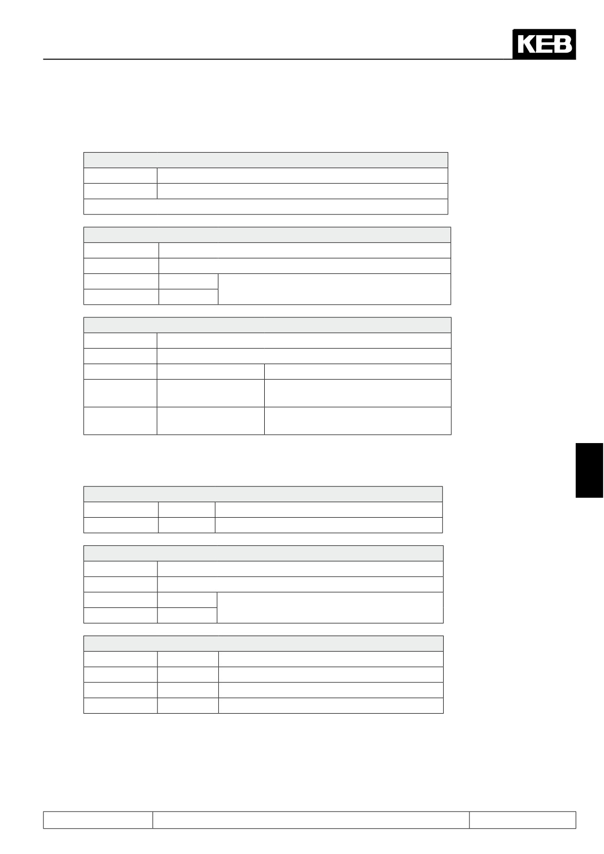
SSI encoder at channel 1
Ec.53: Encoder 1 SSI multiturn res.
Default value
0
Value range
0…13
Number of bits for all revolutions
Ec.43: SSI data code channel 1
Default value
0
Value range
0…1
0
binary
used data format of the encoder
1
Gray
Ec.54: Encoder 1 SSI mode
Default value
0
Value range
0…2
0
Standard
SSI singleturn encoder which shall be
1
Singleturn 25 bit
read out with 25bit
Especially for SIKO encoders at linear
2
Linear (SIKO AE 111)
motors
7.11.12.2
SSI encoder at channel 2
7
Ec.21: SSI multiturn res.
Default value
12
Value range
0…13
Number of bits for all revolutions
Ec.22: SSI Clock frequency selection
Default value
0
Value range
0...1
0
156 kHz
Should not be changed by the default value
1
312 kHz
156khz
Ec.23: SSI data code
Default value
1
Value range
0…1
0
binary
1
Gray
used data format of the encoder
Page7.11 - 19

Speed Measurement
Ec.24: SSI power failure bit
Default value
0
Value range
0…1
0
Off
bit 25 is requested in the SSI protocol 0:ok ;1:er-
1
on
ror
Ec.55: Encoder 2 SSI mode
Default value
0
Value range
0…2
0
Standard
SSI singleturn encoder which shall be read
1
Singleturn 25 bit
out with 25bit
Linear (SIKO AE
Especially for SIKO encoders at linear mo-
2
111)
tors
7.11.12.3
SSI position normalization channel 1 u. 2 (Ec.42)
Ec.42: Encoder alarm mode
Default value
0
Value range
0…15
bit 0: mode channel 1
0
full 32 bit range
Value range of the positioning: 2^31-1... 2^31-1
1
only multiturn range
Value range of 0…2^Ec.52
bit 1: mode channel 2
0
full 32 bit range
Value range of the positioning: 2^31-1... 2^31-1
2
only multiturn range
Value range of 0…2^Ec.52
bit 2: Overflow detection channel 1
0
on
The last position value is compared with the current value
after power on and if necessary overflows in parameter Ec.33
are considered. The prerequisite is that the position has not
changed by half the value range at power-off. Problems with
encoders whose initialisation takes longer than for the inver-
ter. The function must be activated here.
4
Off
Overflow detection not active e.g. linear - axes
bit 3: Overflow detection channel 2
0
on
s.h. bit2 overflow in Ec.34
8
Off
Overflow detection not active e.g. linear - axes
Page7.11 - 20
Speed Measurement
7.11.12.4
Tachometer at channel 2
Ec.25: nominal tachometer speed
Default value
1500 rpm
Value range
0…16000 rpm
Nominal speed of tachometer voltage
7.11.12.5
Evaluation intelligent interface
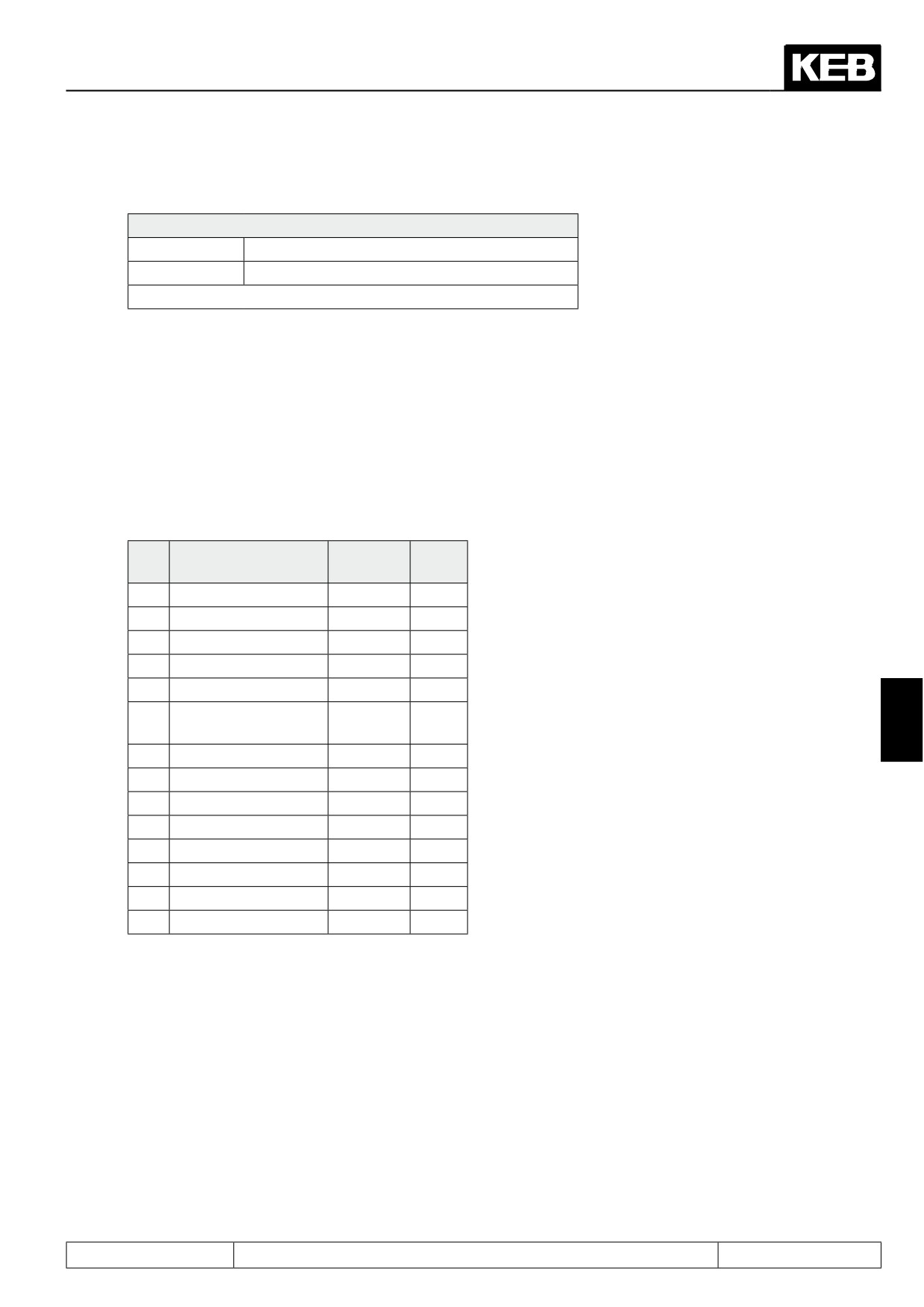
Ec.36 Encoder 1 encoder type
Parameter Ec.36 "encoder 1 encoder type" indicates the type of the supported encoder interface 1 when using
absolute encoders.
Absolute encoders have the characteristic to keep the absolute position value after Power-On-Reset.
The following encoder types are supported:
No.
Encoder type
Hiperface
EN-
DAT
2
SCS 60/70
x
7
SCM 60/70
x
16
SinCos not absolute
17
SinCos absolute
18
SSI absolute
19
UVW without zero
7
track
20
UVW with zero track
34
SRS 50/60
x
39
SRM 50/60
x
49
Endat Singleturn
x
50
Endat Multiturn
x
50
SKS 36
x
51
Endat linear
x
55
SKM 36
x
The resolver is defined as standard interface.
Page7.11 - 21

Speed Measurement
Ec.37 Encoder 1 encoder status:
Parameter Ec.37 "encoder 1 encoder status" indicates the current status of the encoder interface 1 when using
absolute encoders.
If the accumulative error message E.ENC:"Error! Encoder 1" is displayed in inverter state ru.00, then the de-
fined error message can be read in Ec.37.
Ec.37 Enc. 1 encoder status
Value
Description
0
no communication to the interface
16
transmit position
64
encoder not defined
68
no communication to the encoder
69
increase error counter
70
Ec.01 unequal to the encoder type
71
interface identification
75
encoder temperature
76
speed too high
77
int. encoder signals too low
78
int. encoder defect
92
format encoder
96
new encoder identifier
97
invalid data
98
damaged interface
255
no communication to the interface
If an unknown absolute encoder is used that is unsupported by the system, status Ec.37 shows the value 96:
"New encoder identifier", and the error E.ENC is triggered.
Ec.38 Encoder 1 encoder r/w:
Data can be stored and read out in some absolute encoders (e.g. Endat, Hiperface). KEB servo motors with
this absolute encoders already contain the complete motor data. This data are accepted with the first switching
on.
Ec.38 Encoder 1 encoder r/w
Bit
Description
Value
Function
0: reading not active
Activates the reading, value is set to 0
0
read data
1: reading activated
afterwards.
0: Storing not active
Activates the storing, value is set to 0
1
store data
afterwards
(Supervisor-password pro-
2: Storing activated
tected)
load data during switching
0: not automatically
Activates the automatic loading after
2
on
4: automatically
switching on the frequency inverter
0: system and application
motor data, Ec.02, cS.19 and Ec.03
(all)
3...4
data group/ selection
8: System
only motor data and Ec.02
16: only Ec.02
only Ec.02
Page7.11 - 22
Speed Measurement
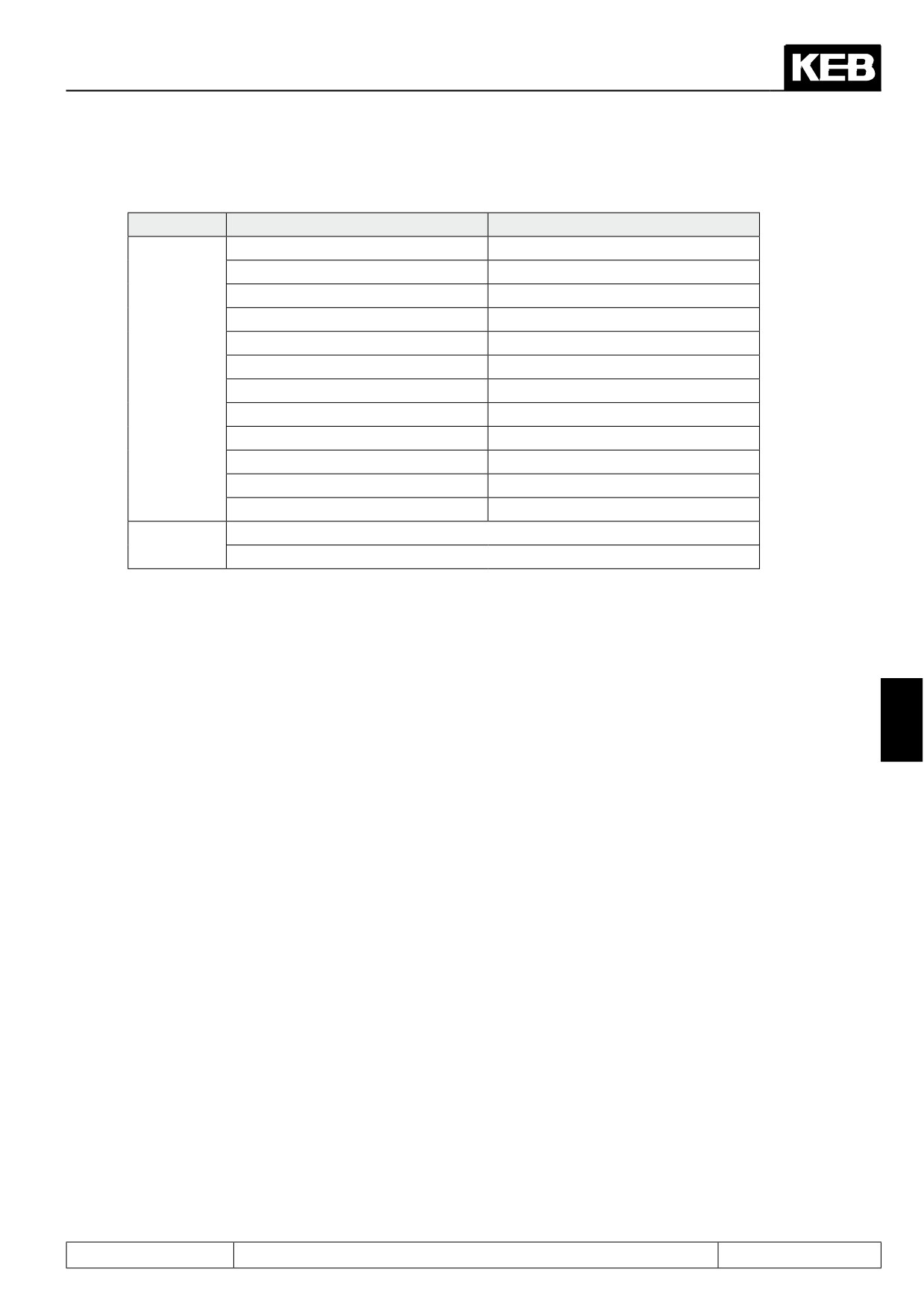
Explanation to bit 3…4
F5-S
F5-M
dr.23 DSM rated current
dr.00 DASM rated current
dr.24 DSM rated speed
dr.01 DASM rated speed
dr.25 DSM rated frequency
dr.02 DASM rated voltage
dr.26 DSM EMK [Vpk*1000RPM]
dr.03 DASM rated power
dr.27 DSM rated torque
dr.04 DASM rated cos(phi)
dr.28 DSM curr. f. zero speed
dr.05 DASM rated frequency
System
dr.30 DSM winding resistance
dr.06 DASM stator resistance
dr.31 DSM winding inductance
dr.07 DASM sigma-inductance
dr.32 DSM rated power
-
dr.33 DSM max. torque
-
Ec.01 encoder (inc/r) 1
Ec.01 encoder 1 (inc/r)
Ec.02 absolute pos. enc.1
-
cS.19 abs. torque ref
Application
Ec.03 time 1 for speed calc.
Data storage:
First the data must be stored on the encoder if a new encoder is used. The supervisor password must be
entered and Ec.38 = 2 must be written for it. In case of successful storage no error message is released and
the bit is automatically reset with this parameter.
The system and application data are always stored!
7
Read data:
The data are read out once from the encoder for F5-S.
If data shall be read manually value 1 and the value of bit 3... 4 must be written.
In case of successful reading no error message is released and the bit is automatically reset with this parame-
ter.
The controller adaptation is automatically released after read out of the data (Fr.10) and pn.61 "Quick stop
torque limit" = cs.19 "absolute torque ref " is set.
If the stored data cannot be read and/or loaded into the frequency inverter, error message E.ENC is released
and parameter Ec.37 displays value 97:"invalid data".
If only the system position is read out then this is depending on the pole-pair number. This pole-pair number is
calculated of dr.24 "rated speed" and dr.25 "rated frequency".
See chapter 7.11 speed measurement for further adjustment possibilities.
Page7.11 - 23

Speed Measurement
When using an intelligent interface the parameters Ec.36, Ec.37, Ec.38 are supported. This interface supports
the following encoder types:
-
Hiperface
-
ENDAT
-
SinCos
-
UVW encoder
-
Overspeed limiter
-
SinCos - SSI
Encoder 1 encoder type (Ec.36)
This parameter gives particular information about the connected encoder:
Ec.36: Encoder 1 encoder type
Value
Plaintext
0
no encoder identified
34
SRS 50/60
39
SRM 50/60
2
SCS 60/70
7
SCM 60/70
64
undefined type
48
ENDAT
17
SinCos abs.
16
SinCos no abs.
49
Endat Singleturn
50
Endat Multiturn
18
SSI abs.
50
SKS 36
55
SKM 36
19
UVW without zero track
20
UVW with zero track
51
Endat linear
Encoder 1 encoder status (Ec.37)
This parameter indicates with different status messages the condition of encoder and interface. Depending on
the encoder only specified messages are possible. All errors are only set at control release, although they are
already displayed in Ec.37.
The following value is displayed at error-free operation:
16: Position values are transmitted, encoder and interface are correct
Page7.11 - 24
Speed Measurement
The following status messages release the error "Error Encoder Change" (E.EncC), because the correct eva-
luation of the position is not longer ensured:
64: Encoder is unknown and is not supported
67: The signals of the incremental track are incorrect, e.g. because no encoder is connected or the en-
coder cable is defective.
68: The signals of the absolute track are incorrect. The absolute track at Endat, Hiperface and SSI-
SinCos is digital, at SinCos it is analog.
69: Position deviation too large. The position, determined from the incremental signals and the absolute
position (absolute track, zero signal or serial read out) do not agree or they cannot be corrected.
70: Adjusted increments per revolution of the inverter does not agree with the encoder increments per
revolution.
71: Interface type is unknown: Interface was not identified.
75: Encoder temperature too high (message from encoder)
76: Speed is too high (message from encoder)
77: Encoder signals are out of specification (message from encoder)
78: Encoder has an internal error (message from encoder)
92: Encoder is formatted. When writing on an encoder, whose storage structure does not correspond to
the KEB definition, the storage areas are reorganised, so that they can be written on. This procedure
can take several seconds, depending on the available memory structure.
96: New value recognised, because another encoder was connected
98: Interface is busy
7
Page7.11 - 25
Speed Measurement
Error E.EncC can only be reset with parameter Ec.0.
Exception:An error due to wrong encoder increments per revolution (value 70) is immediately reset, if the cor-
rect number of increments per revolution is adjusted. Attention, if the control release is still set, the modulation
will be released!
The following status messages release the error "Error Encoder 1" (E.Enc1), if the encoder shall be read out:
97: KEB-identification is undefined. Memory structure in the encoder is not corresponding to the KEB
definition and consequently the data can not be read. The encoder is defined by description. At F5-S
the error can be reset as follows:
•
Writing of a system position in Ec.2.
•
Carry out a system position adjustment
The following status messages release the error "Error Hybrid" (E.HYb):
0, 255: no communication between interface and control board
Encoder 1 encoder r/w (Ec.38) :
Ec.38: Encoder 1 encoder r/w
F5S = 4
Default value
F5M = 0
0
not active
Read data
Bit 0
1
active (reset after reading)
0
not active (1)
Save data
Bit 1
2
active (reset after reading)
0
not automate
Motor data
Bit 2
4
automate (2)
0
System and application data
8
Application data
Data groups
Bit 3, 4
16
only Ec.02
24
reserved
(1) storing is supervisor-password protected, independent of bit 3, 4 all data are stored
(2) Servo power controller with Endat/Hiperface do not receive a factory download of the motor data
(3) cs.19 and Ec.03 belong to the application data
The initial reading-out of the encoder data can be automated depending on bit 2
-
Factory configuration of the F5-S inverter (In.24 = 199 supervisor password)
-
Acknowledgement of the encoder interface change E.HYPC via Ec.00.
-
Loading the system default value (fr.01 = -3,-4)
The following parameters are stored in the encoder dependent on the mode (ASM/SM):
Page7.11 - 26
Speed Measurement
Motor data for servo motors:
Parameter
Description
Resolution
Group
dr.32
DSM rated power
0,01 kW
System
dr.24
DSM rated speed
0,1 rpm
System
dr.23
DSM rated current
0,1 A
System
dr.25
DSM rated frequency
0,1 Hz
System
dr.28
DSM curr. f. zero speed
0,1 A
System
dr.27
DSM rated torque
0,01 Nm
System
dr.33
DSM max. torque
0,01 Nm
System
dr.26
DSM EMK [Vpk * 1000 rpm]
1 V / 1000 rpm
System
dr.30
DSM winding resistance
0,001 Ohm
System
dr.31
DSM winding inductance
0,01 mH
System
Internal release of the controller adaption occurs after read in of the motor data (Fr.10 = 1)
Motor data for asynchronous motors:
Parameter
Description
Resolution
Group
dr.00
DASM rated current
0,1 A
System
dr.01
DASM rated speed
0,1 rpm
System
dr.02
DASM rated voltage
1 V
System
dr.03
DASM rated power
0,01 kW
System
dr.04
DASM rated cos(phi)
0,01
System
dr.05
DASM rated frequency
0,1 Hz
System
7
dr.06
DASM stator resistance
0,001 Ohm
System
dr.07
DASM sigma-inductance
0,01 mH
System
dr.xx
Switching mode for conversion
System
Internal release of the controller adaption occurs after read in of the motor data (Fr.10 = 1),
Encoder parameters:
Parameter
Description
Group
Ec.01
encoder 1 (inc/r)
System
Ec.02
absolute pos. enc.1
System
Ec.03
time 1 for speed calc.
Application
Ec.06
encoder 1 rotation *)
System
Control parameter:
Parameter
Description
Resolution
Group
cs.19
abs torque ref
0,01 Nm
Application
!!!pn.61 = cs.19 is set after reading out the application data!!!
Page7.11 - 27

Speed Measurement
7.11.12.6
Encoder 1 over transmission (Ec.39)
This parameter allows the operation of encoders that either are not mounted directly to the motor (output, belt),
whose detection has a superior position evaluation (e.g., pole-pair resolver), or whose increments per revolu-
tion cannot be set in Ec.01.
Ec.39: Encoder 1 over transmission
0
off
No function
1
Motor - Encoder
Speed ratio in the encoder detection. Position values are evaluated 1:1,
gear factor Ec.04/05 enters the speed measurement.
2
Ec.01 x Ec.05 (1 zero
The increments per revolution of the encoder is greater than the parame-
impulse / revolution)
ter in Ec.01 allows. The zero signal is once per revolution
3
Ec.01 x Ec.05
like 2, but the zero signal is spacer-coded (500inc / 500 inc = zero posi-
(spacer-coded)
tion)
4
Reserved
Special software (like 2, but the zero signal is validated via an external
reference switch).
5
Motor - Encoder +
For channel 1 as 1. The motor is operated under control of an encoder
synchronous channel
coupled to the output. Via channel 2, control occurs position-synchronous.
2
The gear factor in channel 1 is considered in the speed detection of chan-
nel 2, which serves for precontrol.
Page7.11 - 28
Positioning and Synchronous Control
7.1
Operating and appliance data
1.
Introduction
7.2
Analog in- and outputs I
2.
Summary
7.3
Digital in- and outputs
3.
Hardware
7.4
Setpoint-, rotation- and ramp adjustment
Motor data and controller adjustments of the asynchronous
7.5
4.
Operation
motor
Motor data and controller adjustments of the synchronous
7.6
motor
Selection of Operating
5.
Mode
7.7
Speed control
6.
Initial Start-up
7.8
Torque display and -limiting
7.9
Torque control
7.
Functions
7
7.10
Current control, -limiting and switching frequencies
8.
Error Assistance
7.11
Speed measurement
9.
Project Design
7.12
Positioning and synchronous control
7.13
Protective functions
10. Networks
7.14
Parameter sets
11. Parameter Overview
7.15
Special functions
12. Annex
7.16
CP-Parameter definition
Page7.12 - 1
Positioning and Synchronous Control
7.12.1
Limit switch
7.12 - 4
7.12.1.1
Hardware limit switch
7.12 - 4
7.12.1.2
Software limit switch
7.12 - 4
7.12.2
Approach the reference point
7.12 - 5
7.12.2.1
Approach to reference point / modes
7.12 - 6
7.12.2.2
Approach to reference point / stopping point
7.12 - 8
7.12.2.3
Approach to reference point / stop at zero signal
7.12 - 8
7.12.2.4
Approach to reference point / no driving free
7.12 - 9
7.12.2.5
Approach to reference point / limit switch
7.12 - 9
7.12.2.6
Reference point / manual setting
7.12 -
11
7.12.2.6.1
Over PS.14
7.12 -
11
7.12.2.6.2
With input function "set reference point"
7.12 -
11
7.12.2.7
Reference point / valid position
7.12 -
11
7.12.2.8
Approach to reference point / stop at index 0
7.12 -
12
7.12.3
Synchronous mode
7.12 -
13
7.12.3.1
Synchronous mode / principle
7.12 -
13
7.12.3.2
Synchronous mode / premise
7.12 -
14
7.12.3.4
Synchronous mode / position normalisation
7.12 -
16
7.12.3.5
Synchronous mode / selection of operating mode
7.12 -
17
7.12.3.6
Synchronous mode / activation and synchronization
7.12 -
18
7.12.3.6.1
Principle
7.12 -
18
7.12.3.6.2
Synchronization at limit
7.12 -
18
7.12.3.6.3
Synchronization with constant path
7.12 -
19
7.12.3.6.4
Synchronization with ramp
7.12 -
21
7.12.3.7
Gear factor
7.12 -
23
7.12.3.8
Angular correction
7.12 -
24
7.12.3.9
Angular reset
7.12 -
25
7.12.4
Posi mode
7.12 -
26
7.12.4.1
Selection of operating mode
7.12 -
26
7.12.4.2
Posi mode / principle
7.12 -
26
7.12.4.3
Posi mode / premise
7.12 -
28
7.12.4.4
Position normalisation
7.12 -
29
7.12.4.4.1
Position control by the motor encoder
7.12 -
29
7.12.4.4.2
Positioning by the output
7.12 -
30
7.12.4.4.3
Speed and position control by motor encoder/ encoder
mounting via gear
7.12 - 31
7.12.4.5
Posi mode / actual position
7.12 - 33
7.12.4.6
Posi mode / set and target position
7.12 - 33
7.12.4.7
Posi mode / single positioning
7.12 - 34
7.12.4.8
Posi mode / sequential positioning
7.12 - 37
7.12.4.9
Posi mode / Positioning with set changeover
7.12 - 50
7.12.4.10
Posi mode / rotary table
7.12 - 50
7.12.4.10.1 Rotary table with path optimization
7.12 - 51
7.12.4.10.2 Rotary table without path optimization
7.12 - 52
7.12.4.11
Posi mode / defined stop
7.12 - 56
7.12.4.12
Posi mode / remaining distance positioning
7.12 - 57
7.12.4.13
Posi mode / flying referencing with correction
7.12 - 58
7.12.4.14
Posi mode / start positioning
7.12 - 63
7.12.4.15
Posi mode / not reachable positions
7.12 - 67
7.12.4.16
Posi mode / stop positioning
7.12 - 69
7.12.4.17
Analog position setting
7.12 - 70
7.12.4.18
Analog position output
7.12 - 70
Page7.12 - 2
Positioning and Synchronous Control
7.12.4.19
Target window
7.12 - 71
7.12.4.20
Position scan
7.12 - 71
7.12.4.21
Teach function
7.12 - 72
7.12.4.22
Functions and displays for the positioning mode
7.12 - 73
7.12.5
Contouring control mode
7.12 - 75
7.12.5.1
Contouring control mode / premises
7.12 - 75
7.12.5.2
Contouring control mode / settings
7.12 - 76
7.12.5.3
Contouring control mode / write / read data
7.12 - 77
7.12.5.4
Contouring control mode / speed precontrol
7.12 - 77
7.12.5.5
Contouring control mode / watchdog
7.12 - 77
7.12.5.6
Contouring control mode / example
7.12 - 78
7.12.6
Position controller
7.12 - 80
7
Page7.12 - 3