KEB COMBIVERT F5-A,-E,-H 4.0. APPLICATION MANUAL (2008) - page 13
Torque Control
7.9.3. Speed calculation
The setpoint speed according to the ramp generator (ru.02) is used for speed limiting.
The setpoint speed is formed (with exception of the direction of rotation) exactly as in the vector controlled and
open loop operation, respectively. The direction of rotation is indicated by the sign of the torque reference.
Without limiting the speed, the drive would accelerate to indefinitely high speeds if the counter torque disap-
pears.
Since the limiting is based on the speed at the ramp generator output, the acceleration-/deceleration ramps
should be set to 0 s for this operating mode.
7.9.4. Control mode
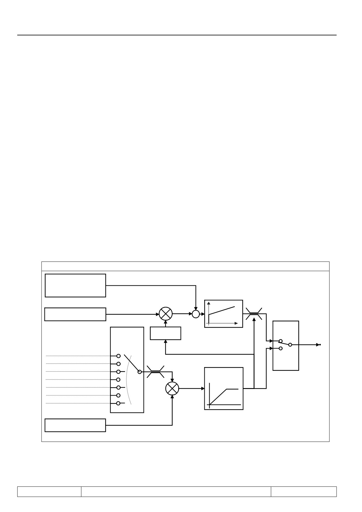
For the torque-controlled operation, 2 different modes exist that can be selected with cS.00 = 5 or cS.00 = 6 .
7.9.4.1Mode 1: torque-controlled operation with emergency switching to speed control
This mode is activated via cS.00 = 5.
The speed controller is not active as long as the drive does not exceed the maximum speed for torque-con-
trolled operation (= setpoint speed ru.02) .
This has the advantage that the parametrisation of the speed controller has no effect on the set torque.
The switch to vector controlled operation happens only on reaching the speed limit. The switching causes sub-
optimal controller behaviour and overshoots can occur.
Figure 7.9.4.1 Mode 1
ru.07
"Actual value display"
(Actual speed)
Speed controller
Set
Set
torque
speed
-
Amount of parameter ru.02
"Ramp output display"
Actual speed
CS.15
>
Sign
Set speed
Torque
Torque
reference
reference
source
Analog ref
0
Speed
controller in
Analog aux
1
+100%
limit
Abs. torque reference (CS.19)
2
"Actual ref.
Torque ref. setting % (CS.18)
3
-100%
Torque acc. time
torque" ru.49
CS.16
Motor poti (ru.37)
4
Ext. PID outdisp. (ru.52)
5
AN2 direct (quick scanning)
6
CS.19
"Absolute torque reference"
Page7.9 - 4
Torque Control
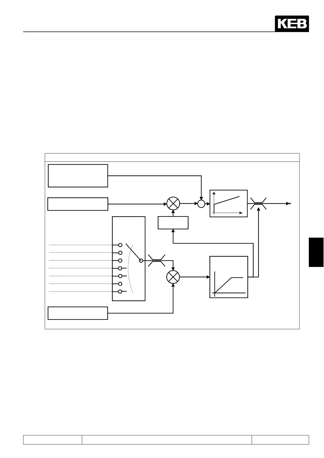
7.9.4.2Mode 2: torque-controlled operation with superimposed speed control
This mode is activated via cS.00 = 6.
The speed controller is permanently active, but the limit of the controller is always set equal to the torque re-
ference.
As long as the drive does not exceed the maximum speed for torque-controlled operation (= setpoint speed ru.
2), the speed controller is within the limits, i.e., its output signal is equal to the torque reference.
This mode has<the advantage that the speed controller is always active, leading to better behaviour when
reaching the maximum speed .
The disadvantage is that with an unfavorable parametrisation of the speed controller (e.g., very small amplifica-
tion chosen), the torque reference can be further delayed by the controller. I.e., even if the ramp time is cS.16
= 0:off, the speed controller must first run to the new limit value after an increase of the torque reference .
Figure 7.9.4.2 Mode 2
ru.07
"Actual value display"
(Actual speed)
Speed controller
Set
Set
Torque
torque
speed
-
reference
Amount of parameter ru.02
"Ramp output display"
CS.15
Sign
Torque
reference
source
Analog ref
0
Analog aux
1
+100%
7
Abs. torque reference (CS.19)
2
"Actual ref.
Torque ref. setting % (CS.18)
3
-100%
Torque acc. time
torque" ru.49
CS.16
Motor poti (ru.37)
4
Ext. PID out disp. (ru.52)
5
AN2 direct (quick scanning)
6
CS.19
"Absolute torque reference"
Page7.9 - 5
Torque Control
Page7.9 - 6
Current Control, -Limiting and Switching Frequencies
7.1
Operating and appliance date
1.
Introduction
7.2
Analog in- and outputs I
2.
Summary
7.3
Digital in- and outputs
3.
Hardware
7.4
Setpoint-, rotation- and ramp adjustment
Motor data and controller adjustments of the asynchronous
7.5
4.
Operation
motor
Motor data and controller adjustments of the synchronous
7.6
motor
Selection of Operating
5.
Mode
7.7
Speed control
6.
Initial Start-up
7.8
Torque display and -limiting
7.9
Torque control
7.
Functions
7
7.10
Current control, -limiting and switching frequencies
8.
Error Assistance
7.11
Speed measurement
9.
Project Design
7.12
Positioning and synchronous control
7.13
Protective functions
10. Networks
7.14
Parameter sets
11. Parameter Overview
7.15
Special functions
12. Annex
7.16
CP-Parameter definition
Page7.10 - 1
Current Control, -Limiting and Switching Frequencies
7.10.1
Current control
7.10 - 3
7.10.2.
Current limit
7.10 - 4
7.10.3
Switching frequencies and derating
7.10 - 5
7.10.3.1
Switching frequency (uF.11, In.03, In.04, ru.45)
7.10 - 5
Page7.10 - 2
Current Control, -Limiting and Switching Frequencies
7.10 Current control, -limiting and switching frequencies
7.10.1Current control
Current controller (dS.00 „KP current“, dS.01 „KI current“) are automatically pre-charged by operation of Fr.10
by means of equivalent circuit data.
The controller parameters are calculated from the equivalent circuit data.
The current decoupling must be activated for an optimal control characteristic.At the asynchronous motor it is
differentiated between "1: on "and "2: on, without main inductance".
Mode 2 (without main inductance) must be used if strong DC link voltage fluctuations occur (e.g. at compliant
supply or spindle motors). The complete decoupling can lead to boosted current oscillation.
Otherwise mode „1: on“ for synchronous and asynchronous motor must be selected.
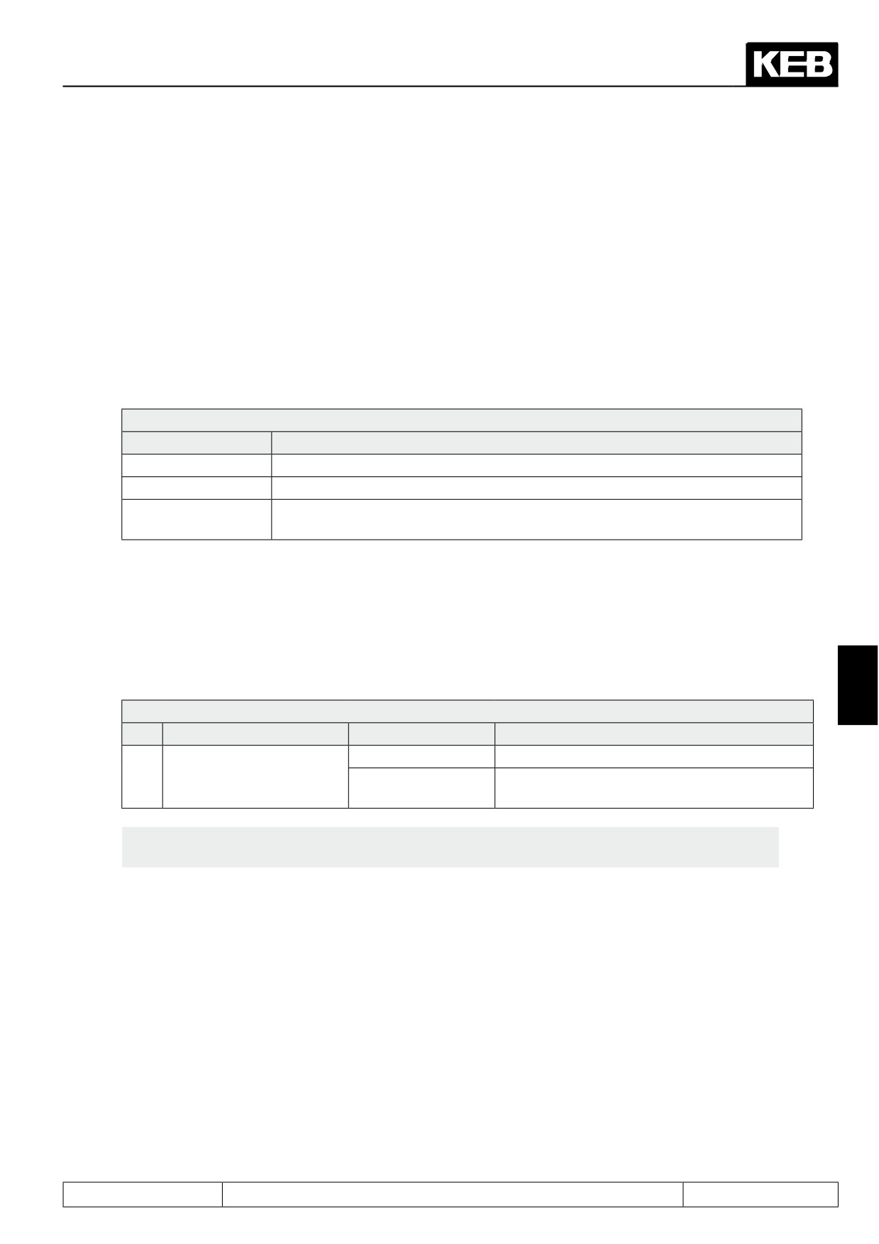
dS.02: Current decoupling
Value
Explanation
0: off
Current decoupling off
1: on
Current decoupling on
2: on, without main
partial current decoupling (mode only for asynchronous motors at unsteady DC
inductance (ASM)
link voltage)
Exception: The controller parameters are only calculated depending on the motor type plate data at speed
controlled operation of an asynchronous motor without motor model. These adjustments are default values
for standard motors and they are not suitable for special motors (e.g. high and medium frequency motors). A
manual adaption must be made here.
A current decoupling is also not possible since the equivalent circuit data are unknown. Parameter ds.02 must
set to value 0.
7
dS.03: Current / torque mode
Bit
Meaning
Value
Explanation
0: off
Current controller/ priority
4
Activation of the active current controller-priori-
assignment (ASM)
16: on
ty in the regenerative range
Attention: A change of bit 4 in parameter ds.03 is usually not necessary and should be done
only by authorized KEB service personnel.
The active current controller can get priority in generatoric operation with bit 4 of parameter ds.03. In special
applications this is of advantage for the quality of the current control.
Page7.10 - 3
Current Control, -Limiting and Switching Frequencies
7.10.2.
Current limit
The hardware current limit becomes active, if the phase current exceeds the value in In.18 „hardware current
inverter“.
Through short-time power shutdown the current limit can avoid short current peaks at small speed, e.g. when
starting the motor.
However if the current level is exceeded at high speed under load, disconnection of the voltage leads to a
reduction of the breakdown torque of the motor and thus to a "fall back" of the motor. The motor model is also
invalid. Therefore this function should be switched off for controlled drives.
Attention: The hardware current limit limits the current at the limit and releases no error. This can lead to torque
sags at the motor shaft. This function is very critical especially at the operation "hoist and lowering". Because
the drive can sag caused by missing torque, without brake engage.
Sole exception: Current overshoots can occur during the start in speed controlled operation with encoder feed-
back without motor model if the current controllers are not optimal adjusted. They can be absorbed with uF.15
= 1: "single-phase mode".The hardware current limiting makes sense also at controlled drives.
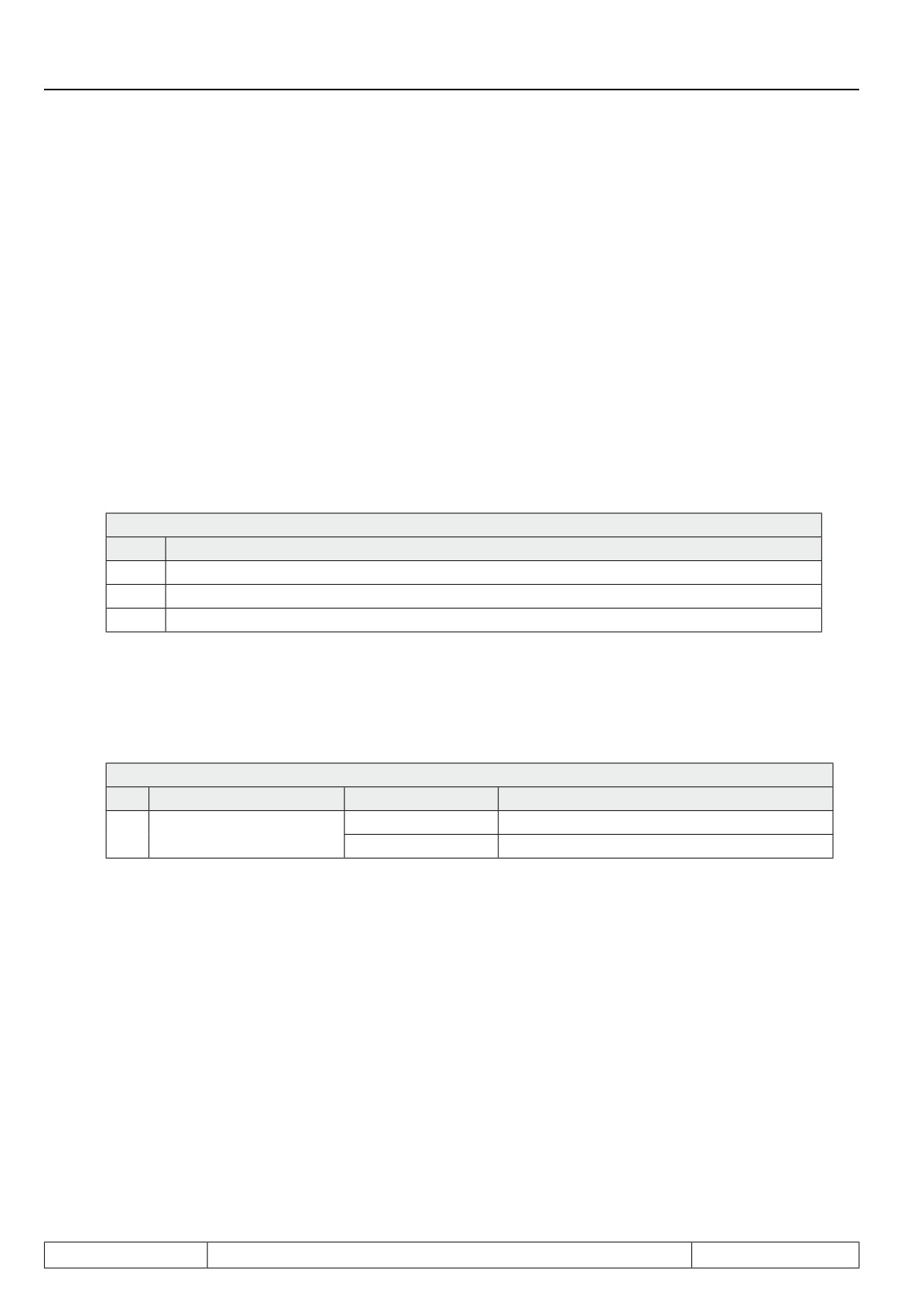
uF.15 Hardw. curr. lim. mode
Value
Explanation
0
Off: recommended adjustment at controlled operation
1
Single-phase mode: limits the current reliably, but deep current engage
2
Zero vector mode: lower current engage, but overcurrent errors can occur in unusual cases.
The software current limiting should be used instead of the hardware protective function. The maximal permis-
sible current must be entered in parameter dr.37.
It is reasonable to enter the hardware current level (In.18) here if the application does not require another value.
The function is activated by setting "curr./torq.mode = 1: on" in parameter (ds.03).
dS.03: Current / torque mode
Bit
Meaning
Value
Explanation
0: off
0
Maximum current mode
1: on
Activation of the software current limiting
Page7.10 - 4
Current Control, -Limiting and Switching Frequencies
7.10.3Switching frequencies and derating
7.10.3.1
Switching frequency (uF.11, In.03, In.04, ru.45)
The desired switching frequency can be selected in parameter uF.11. The higher the switching frequency the
smaller the noise level and the smaller the current ripple and the losses in the motor involved. Simultaneously
the losses in the inverter and also the isolation straining of the motor increase caused by switching edges.
uF.11 Carrier frequency
Value
Frequency
0
2 kHz
1
4 kHz
2
8 kHz
3
12 kHz
4
16 kHz
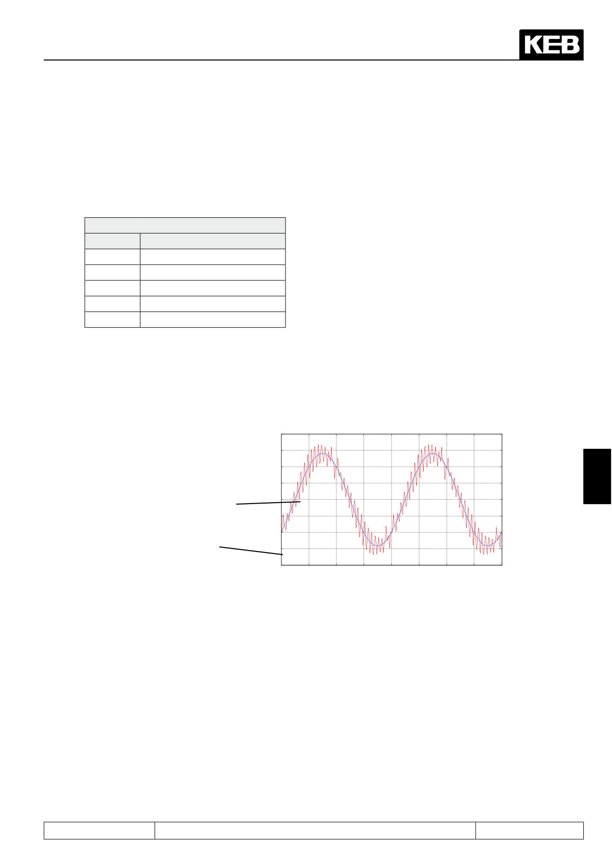
The current ripple is a harmonic current which superimposes the sine-wave output current.
It is generated by the clocked output voltage of the frequency inverter. This ripple increases the maximum value
of the current and this can release an overcurrent error or hardware current limit, although the displayed appa-
rent current (ru.15) and/or the actual utilization value (ru.13) is clearly below this limits.
Picture 7.10.3.1 Switching frequencies
20
15
10
Base frequency of the phase
5
7
current
0
-5
actual current = base frequency
-10
with superimposed ripple
-15
-20
0.0955
0.096
0.0965
0.097
0.0975
0.098
0.0985
0.099
0.0995
The size of the current ripple is depending on the switching frequency and the motor inductance. The current
ripple is usually insignificant for standard motors with a power < 50kW and a rated switching frequency of the
unit of min. 4 kHz.
The smaller the leakage inductance (ASM) and/or the winding inductance (SM) the higher the ripple. This is
especially the case at motors with high power or spindle motors. Therefore the switching frequency must be
selected as high as possible for these motors.
Attention: Generally the switching frequency should be at least 10 times higher than the maximally occuring
output frequency of the inverter.
The maximum switching frequency can be read off in parameter In.03. The frequency inverter can be operated
permanently only with its rated carrier frequency (In.04) (independent on temperature and utilization).
If a switching frequency is selected in parameter uF.11 which is higher than the rated value, an automatic
"derating" i.e. a reduction of the switching frequency occurs depending on temperature, output frequency and
utilization of the inverter. This carrier frequency change-over is generally not good for the control response of
the drive. Therefore the carrier frequency uF.11 should be equal to the rated carrier frequency. However the
effects of the deratings can be neglected in many applications.
Page7.10 - 5
Current Control, -Limiting and Switching Frequencies
Page7.10 - 6
Speed Measurement
7.1
Operating and appliance data
1.
Introduction
7.2
Analog in- and outputs I
2.
Summary
7.3
Digital in- and outputs
3.
Hardware
7.4
Setpoint-, rotation- and ramp adjustment
Motor data and controller adjustments of the asynchronous
7.5
4.
Operation
motor
Motor data and controller adjustments of the synchronous
7.6
motor
Selection of Operating
5.
Mode
7.7
Speed control
6.
Initial Start-up
7.8
Torque display and -limiting
7.9
Torque control
7.
Functions
7
7.10
Current control, -limiting and switching frequencies
8.
Error Assistance
7.11
Speed measurement
9.
Project Design
7.12
Positioning and synchronous control
7.13
Protective functions
10. Networks
7.14
Parameter sets
11. Parameter Overview
7.15
Special functions
12. Annex
7.16
CP-Parameter definition
Page7.11 - 1
Speed Measurement
7.11.1
Designs
7.11 - 3
7.11.2
Encoder interface channel 1 (X3A)
7.11 - 4
7.11.2.1
TTL incremental encoder input (standard at F5-M)
7.11 - 4
7.11.3
Encoder interface channel 2 (X3B)
7.11 - 6
7.11.3.1
Incremental encoder input
7.11 - 6
7.11.3.2
Incremental encoder output
7.11 - 7
7.11.4
Voltage supply of encoder
7.11 - 8
7.11.5
Selection of encoder
7.11 - 8
7.11.5.1
Cable length
7.11 - 9
7.11.5.2
Signal sequence / level
7.11 -
10
7.11.6
Encoder identifier
7.11 -
11
7.11.7
Basic settings
7.11 -
12
7.11.8
Gear factor
7.11 -
14
7.11.8.1
Definition
7.11 -
14
7.11.8.2
Gear factor / analog setting
7.11 -
16
7.11.8.3
Gear factor / set-programming
7.11 -
16
7.11.9
Operation mode output
7.11 -
17
7.11.10
Absolute position encoder 1 / 2 (Ec.02 / Ec.12) (only for F5-S)
7.11 -
18
7.11.11
System offset (Ec.33 / Ec.34)
7.11 -
18
7.11.12
Further parameter / encoder
7.11 -
18
7.11.12.1
SSI encoder at channel 1
7.11 -
19
7.11.12.2
SSI encoder at channel 2
7.11 -
19
7.11.12.3
SSI position normalization channel 1 u. 2 (Ec.42)
7.11 -
20
7.11.12.4
Tachometer at channel 2
7.11 -
21
7.11.12.5
Evaluation intelligent interface
7.11 -
21
7.11.12.6
Encoder 1 over transmission (Ec.39)
7.11 -
28
Page7.11 - 2
Speed Measurement
7.11 Speed measurement
7.11.1 Designs
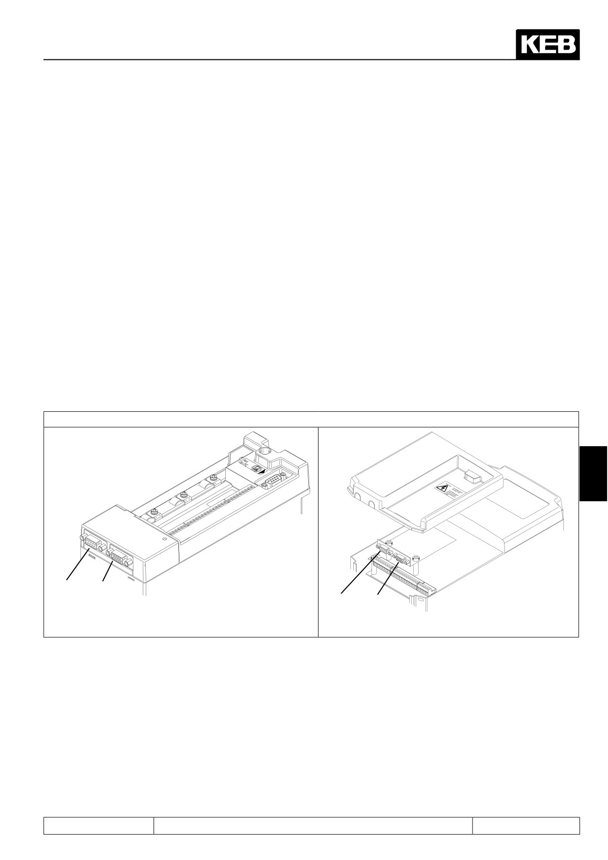
The KEB COMBIVERT F5 supports two from each other separated encoder channels. Each encoder channel
can support following interface dependent on the available hardware:
Encoder channel 1 (X3A)
•
is a 15 pole incremental encoder input for rectangular signals
Encoder channel 2 (X3B) can support following interfaces
•
9 pole incremental encoder input for rectangular signals
•
Incremental encoder output
•
Incremental encoder in-/output
Further interfaces (describes in separate manuals)
•
Synchronous serial interface (SSI)
•
Tachometer input
•
Initiator input
•
Hiperface
•
Endat
•
SinCos
7.11.1 Encoder interfaces
7
X3B X3A
X3B X3A
Page7.11 - 3
Speed Measurement
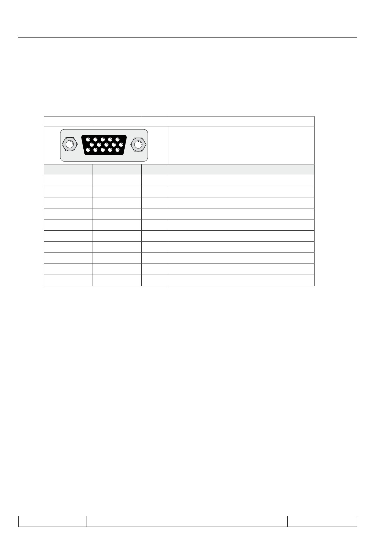
7.11.2 Encoder interface channel 1 (X3A)
7.11.2.1
TTL incremental encoder input (standard at F5-M)
Fig. 7.11.2
Encoder Interface Channel 1 (X3A)
Only when the inverter is switched off and the
5
4
3
2
1
voltage supply is disconnected may the plug
10
9
8
7
6
be pulled out or plugged in !
15
14
13
12
11
Signal
X3A
Description
Uvar
11
Supply voltage for encoder
+5 V
12
Supply voltage for encoder
0 V
13
Reference potential
A
8
Signal input A
_
A
3
Signal input A inverted
B
9
Signal input B
4
Signal input B inverted
n
15
Reference marking input N
14
Reference marking input N inverted
Shield
housing
shielding
Following specifications apply to the encoder interface 1 (X3A):
-
Limiting frequency of input fG = 300 kHz
-
internal terminating resistor Rt = 150 ohm
-
2…5 V High level at rectangular signals
Inputs
The signal and reference marking inputs can be triggered with rectangular pulses. The signal inputs must ge-
nerally be connected. The reference marking signals are only needed for the reference point approach in the
positioning operation (F5M/S).
Please contact KEB regarding encoder inputs with HTL level!
Page7.11 - 4
Speed Measurement
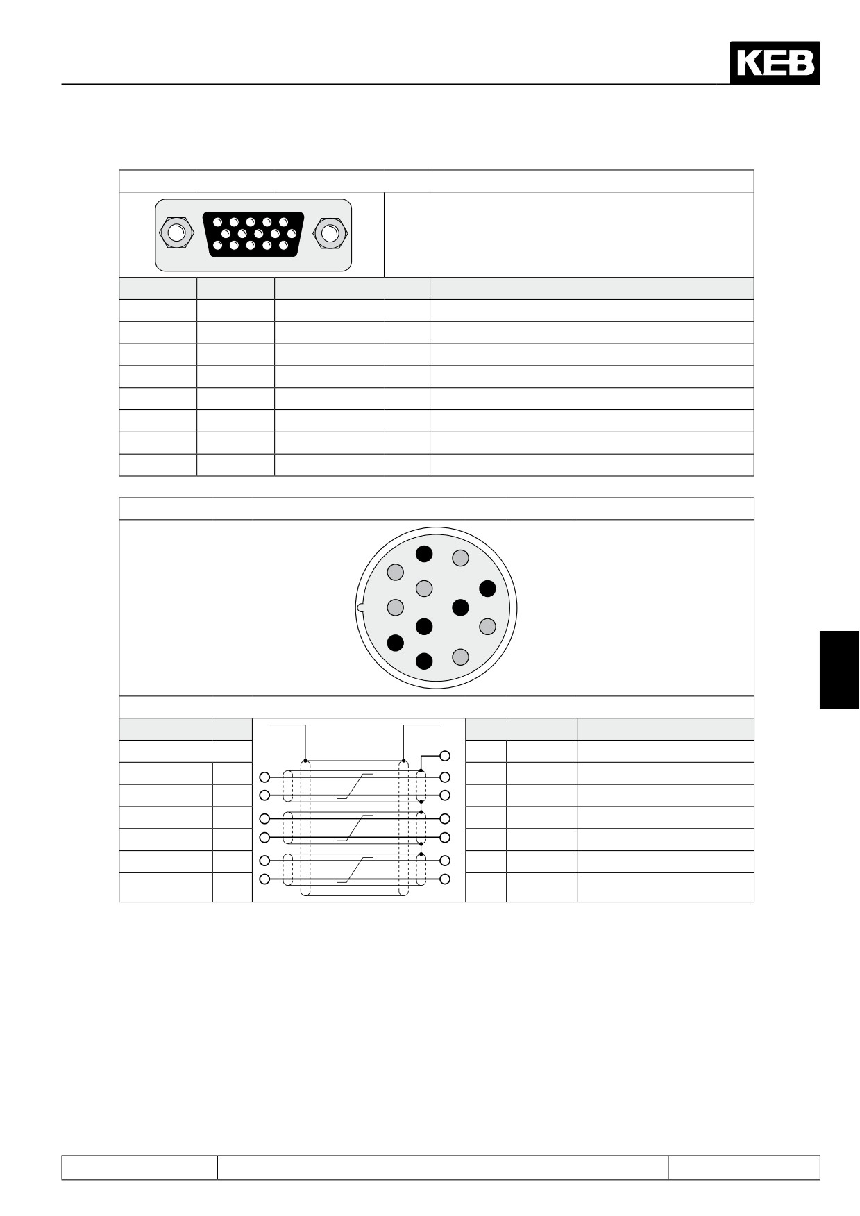
Fig.7.11.2.a Resolver interface channel 1 (X3A)
Only when the inverter is switched off and the vol-
5
4
3
2
1
tage supply is disconnected the plugs may be pulled
10
9
8
7
6
out or plugged in !
15
14
13
12
11
Signal
X3A
KEB servo motor
Description
SIN -
3
1
Sinus signal cable inverted
SIN+
8
10
Sinus signal cable
REF-
5
5
Reference signal inverted
REF+
10
7
Reference signal
COS-
4
2
Cosine signal cable inverted
COS+
9
11
Cosine signal cable
GND
14
-
Shielding of the signal cables
Shield
housing
housing
shielding of the hole cable
Fig. 7.11.2.b Resolver connector at the KEB servo motor
7
6
8
12
5
9
11
10
1
4
2
3
7
Fig. 7.11.2.c Resolver cable
housing
housing
Core color
14
GND
SIN-
1
3
SIN -
red
SIN+
10
8
SIN+
blue
REF-
5
5
REF-
yellow
REF+
7
10
REF+
green
COS-
2
4
COS-
pink
COS+
11
9
COS+
gray
Page7.11 - 5
Speed Measurement
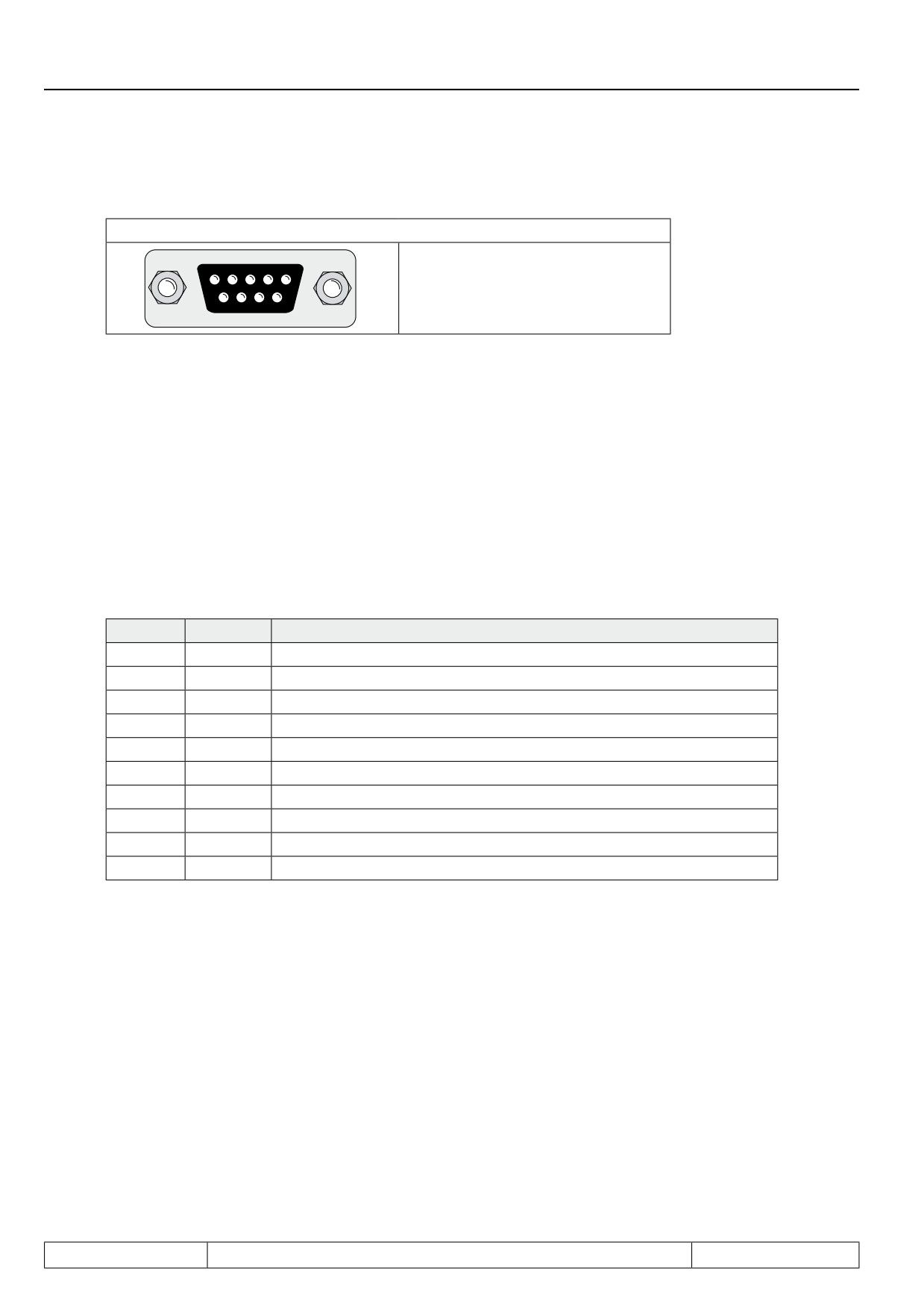
7.11.3 Encoder interface channel 2 (X3B)
Fig. 7.11.3
Encoder interface channel 2 (X3B)
Only when the inverter is switched
5
4
3
2
1
off and the voltage supply is dis-
connected may the plug be pulled
9
8
7
6
out or plugged in !
Channel 2 can be equipped with different interfaces. To avoid the connection of a wrong encoder, the installed
interface is indicated in Ec.10.
Definition of the interface (Ec.10)
Channel 2 can be equipped with different interfaces. To avoid the connection of a wrong encoder, the installed
interface is indicated in Ec.10.
7.11.3.1
Incremental encoder input
In synchronous operation the second incremental encoder serves as input of the master drive. A second posi-
tion encoder can be connected for positioning operation.
Signal
X3B
Description
Uvar
5
Supply voltage for encoder (see 7.11.2)
+5,2V
4
Supply voltage for encoder (see 7.11.2)
0 V
9
Reference potential
A
1
Signal input A
_
A
6
Signal input A inverted
B
2
Signal input B
_
B
7
Signal input B inverted
n
3
Reference marking input N
_
N
8
Reference marking input N inverted
Shield
housing
shielding
The signal inputs of the second encoder interface support only rectangular signals.
Following specifications apply to the encoder interface 2 (X3B):
-
Limiting frequency of input fG = 300 kHz
-
internal terminating resistor Rt = 150 Ω
-
2…5 V High level at rectangular signals
Page7.11 - 6
Speed Measurement
7.11.3.2
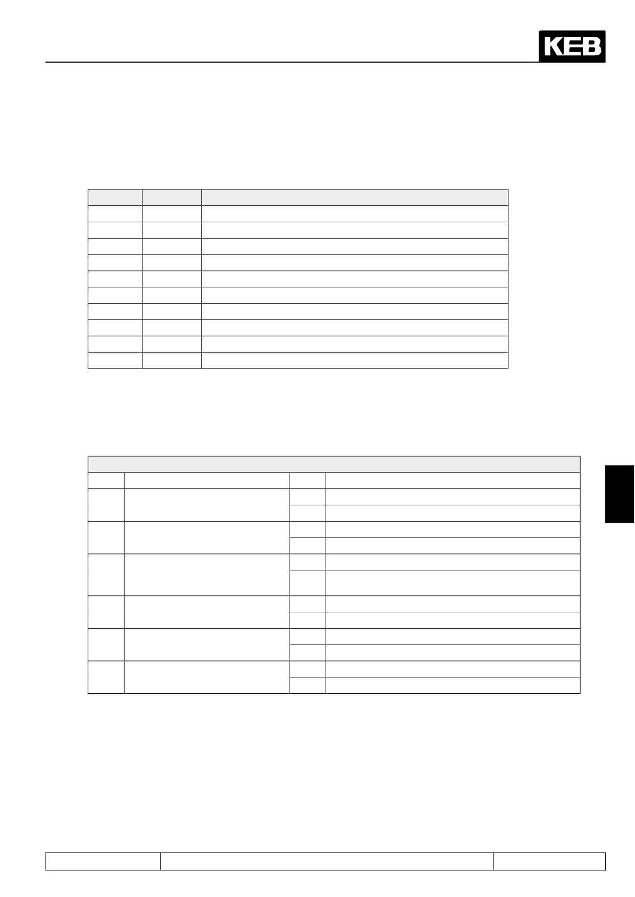
Incremental encoder output
The incremental encoder output gives out the signals recorded at the encoder interface 1:1 in RS422 specifi-
cation over the second channel (e.g. master drive in synchronous operation).
Signal
X4A
Description
Uvar
5
Supply voltage for encoder (see 7.11.2)
+5,2V
4
Supply voltage for encoder (see 7.11.2)
0 V
9
Reference potential
A
1
Signal input A
_
A
6
Signal input A inverted
B
2
Signal input B
_
B
7
Signal input B inverted
n
3
Reference marking input N
_
N
8
Reference marking input N inverted
Shield
housing
shielding
Encoder 2 operating mode (Ec.20)
The function of the encoder interfaces is defined with parameter Ec.20.
Ec.20: Encoder 2 operating mode
Bit
Description
Value
Function
0
Incremental encoder input
7
1
Channel 2 Function
1
Incremental encoder output
0
Input with terminating resistor
2
Terminating resistor at channel 2
2
Input without terminating resistor
Channel 1 incremental encoder
0
without alarm
3
alarm
(encoder breakage refe-
4
with alarm (encoder must support alarm)
rence)
channel 2 incremental encoder
0
without alarm
4
alarm
8
with alarm (encoder must support alarm)
channel
1 without incremental
0
without alarm
5
encoder
16
with alarm
channel
2 without incremental
0
without alarm
6
encoder
32
with alarm
Page7.11 - 7
Speed Measurement
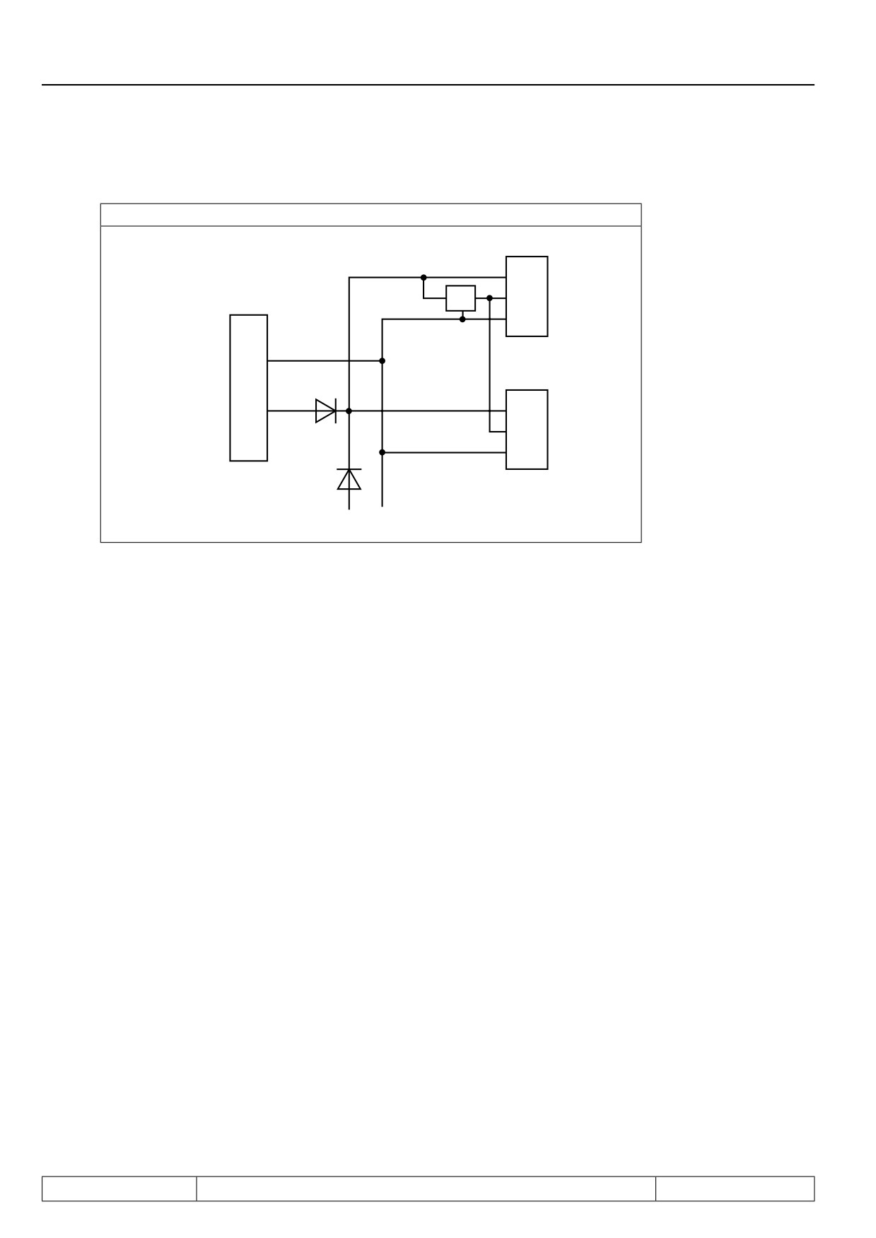
7.11.4 Voltage supply of encoder
Fig. 7.11.4 Voltage supply
X3A
Uvar
5,2V
+5,2V
X2A
0V
0V
22
X3B
+20...30VDC
21
Uvar
+5,2V
0V
+24VDC 0V
Uvar , +5 V
Uvar is a unstabilized voltage, which is made available from the power circuit of the KEB COMBIVERT. Depen-
ding on the unit size and the load it can be 15...30 V DC. Uvar can be loaded at X3A and X3B altogether with
max.170 mA. If higher currents are required for the supply of the incremental encoder, the FI must be supplied
with an external voltage.
The +5,2 V voltage is a stabilised voltage, which at X3A and X3B is loadable with altogether 500 mA. Since the
+5,2 V are generated from Uvar, the current from Uvar decreases in accordance with following formula:
5,2 V x I+5V
Ivar = 170 mA -
-————
Uvar
7.11.5 Selection of encoder
Precondition for a good control characteristics of a drive is not at least a question of the selection and the cor-
rect connection of the encoder. This also includes the mechanical as well as the electrical connection.
Max. operating frequency (max.sampling frequency)
Depending on the max. operating frequency of the encoder input, the encoder and the maximum speed of the
drive the line number of the encoder can be selected.
Page7.11 - 8
Speed Measurement
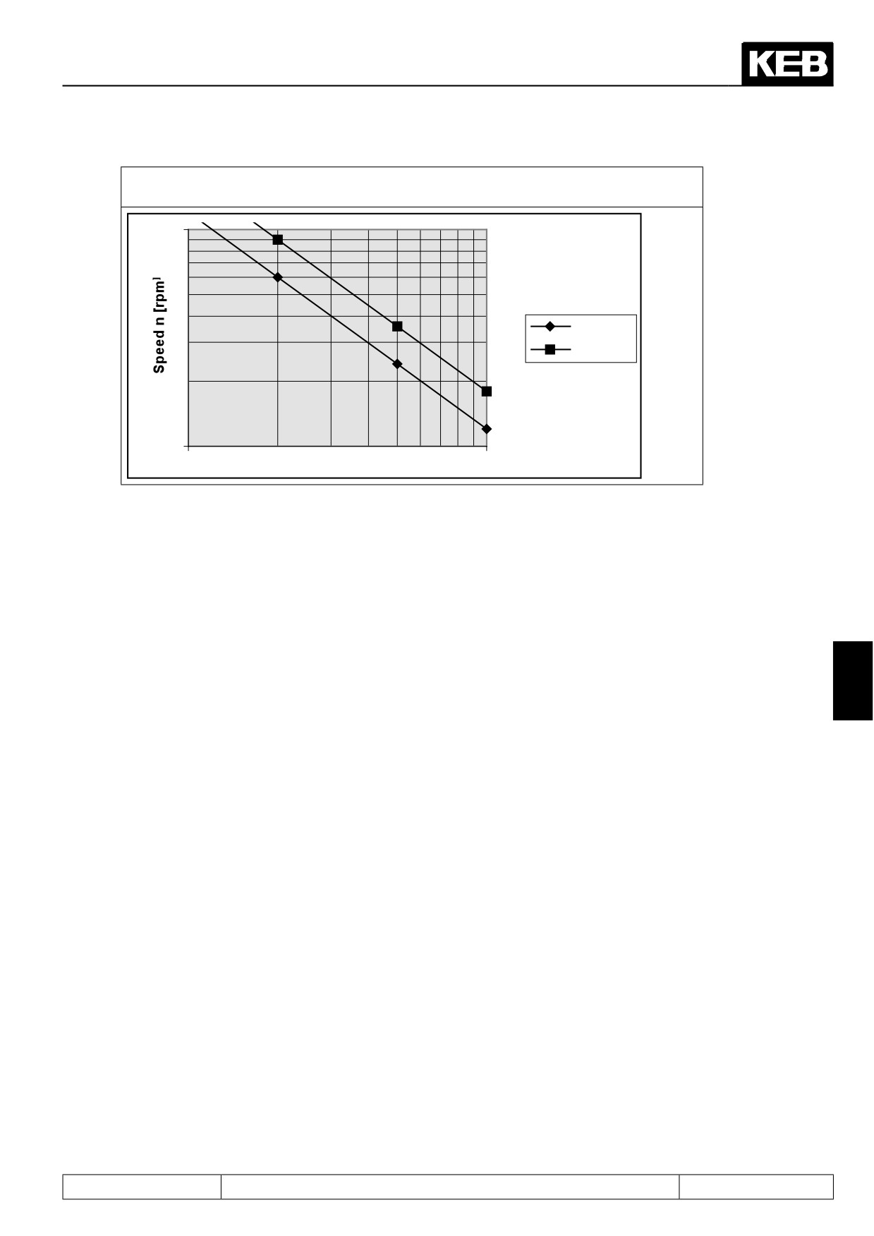
7.11.5 Speed and line number in dependence on the max. operating frequency of the
encoder inputs
10000
200 kHz
300 kHz
1000
1000
Line number z
10000
The max. signal frequency, which is given out by the encoder, is calculated as follows:
nmax[rpm] x z
fmax [kHz] =
-——————
60000
fmax:
max. signal frequency
7
nmax: max. speed
z:
encoder line number
The following condition must be met:
fmax < max. operating frequency of encoder < max. operating frequency of interface
7.11.5.1
Cable length
To achieve an unobjectionable function following cable lengths should not be exceeded. Precondition is that the
supply voltage at the rotary encoder is within the specified tolerances.
The encoder lines should not be longer than 50 m. If longer cables are needed, please contact KEB.
Further information can be taken from the documentation of the respective manufacturer.
Page7.11 - 9
Speed Measurement
7.11.5.2
Signal sequence / level
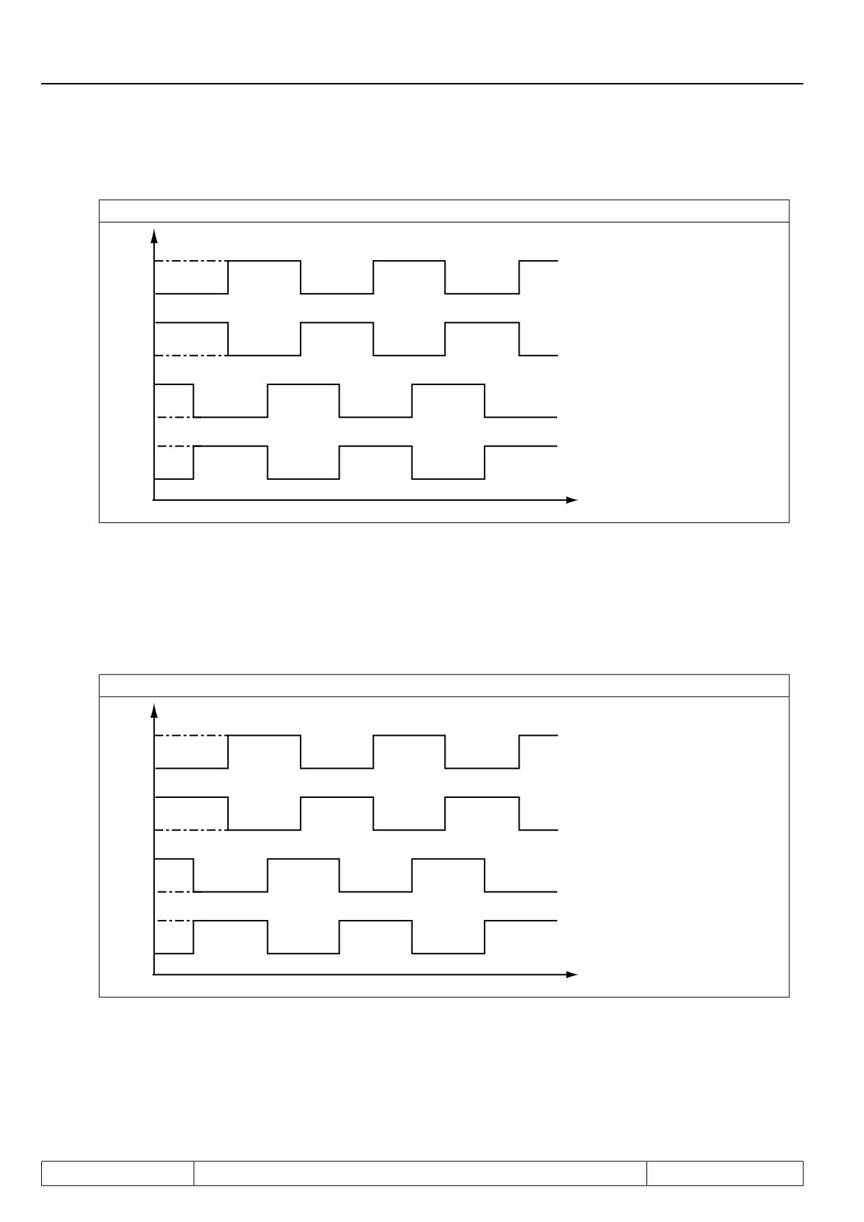
7.11.5.a Signal tracks A+, B+
!
6
#/-
6
!
6
#/-
6
"
6
#/-
6
"
6
#/-
6
T
Evaluation of the zero signal
The zero signal is required for referencing and/or correction of the position value. The signal must not be con-
nected at normal speed controls (see alarm evaluation Ec.41). The maximum permissible length of the zero
signal of the encoder is visible in the following signal sequence. The zero signal is acquired when A+ ,B+ and
N+ are on high level. Thus there is only one valid position value independent of the travel direction.
7.11.5.b Evaluation of the zero signal
!
6
#/-
6
!
6
#/-
6
"
6
#/-
6
"
6
#/-
6
T
Page7.11 - 10
Speed Measurement
7.11.6 Encoder identifier
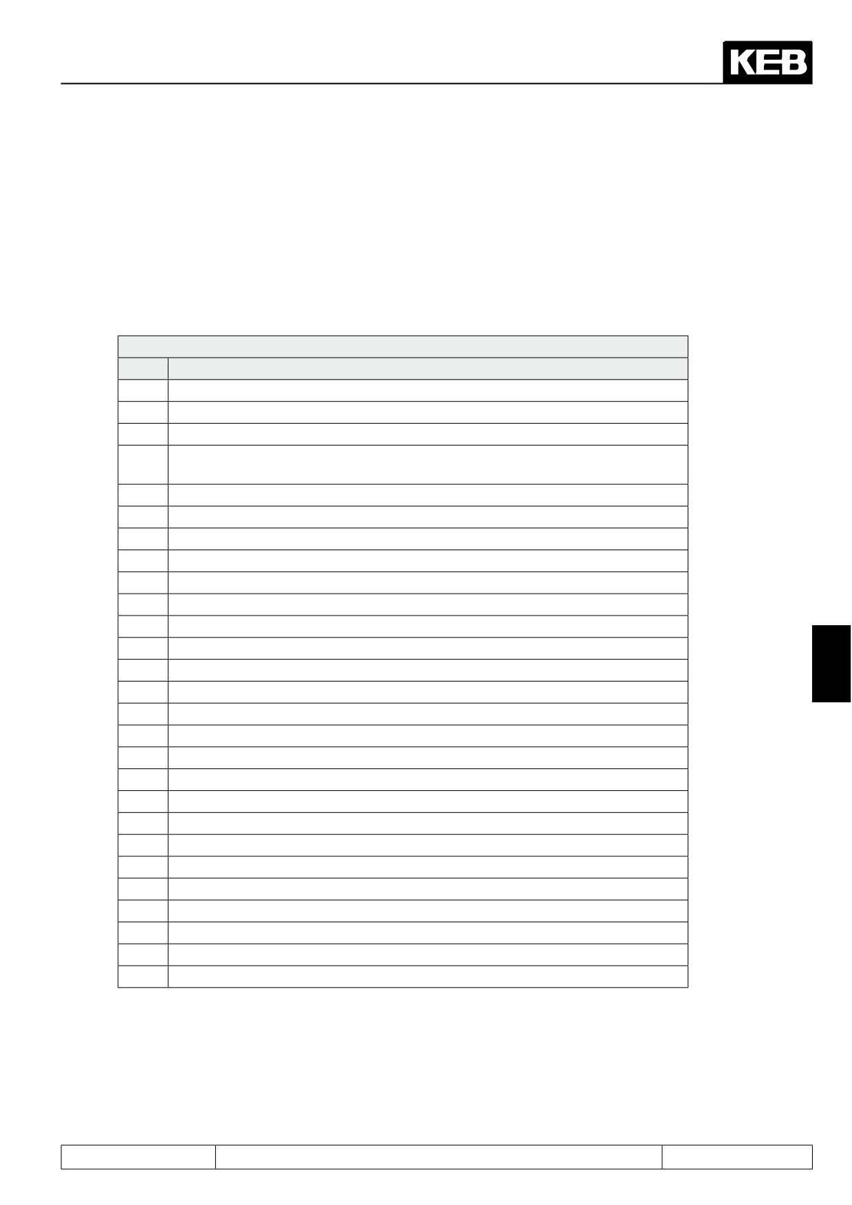
Prior to start-up the inverter must be adapted to the encoder(s) which is/are used.
Encoder interface 1 / 2 (Ec.00, Ec.10)
Ec.00 displays the installed encoder interface 1; Ec.10 displays the encoder interface 2. The values correspond
to following interfaces:
Ec.00, Ec.10: Encoder interface 1/ 2
Value
Description
0
no
1
TTL-Incremental encoder input
2
Incremental encoder output 5 V TTL
3
Incremental encoder input and output direct
(non-divisible with Ec.27; switchable with Ec.20)
4
Incremental encoder input and output TTL (switchable with Ec.20)
5
Initiator
6
Synchronous serial interface (SSI)
7
Resolver
8
Tachometer
9
Incremental encoder output TTL (from resolver over channel 2)
10
Incremental encoder output TTL
11
Hiperface
7
12
Incremental encoder input 24 V HTL
13
Incremental encoder input TTL with error detection
14
SinCos encoder input
15
Incremental encoder input 24 V HTL with error detection (push-pull)
16
ENDAT
17
Incremental encoder input 24 V HTL with error detection
18
Analog option ±10 V
19
Resolver
20
SSI sincos
21
Overspeed limiter
22
UVW-Interface
23
Inc. simulation 10-30V
24
Inc. simulation 10-30V
25
Overspeed limiter HTL
26
Inc. input TTL with error detection 5V supply terminal
In case of an invalid encoder identification, error "E.Hyb" is indicated and the measured value is displayed
inverted in Ec.00 / Ec.10.
On changing the encoder interface the error "E.HybC" is indicated. By writing on parameter Ec.00 or Ec.10 the
change is confirmed and the default values for the new interface are loaded.
Page7.11 - 11