KEB COMBIVERT F5-A,-E,-H 4.0. APPLICATION MANUAL (2008) - page 11
Motor Data and Controller Adjustments of the Synchronous Motor
7.6.3.3.1
Auto-identification
The automatic identification can be carried out with rotation (dr.48=8) or without rotation (dr.48 = 7) (see table
dr.48). Measurement of the dead time compensation characteristics as well as stator resistance and leakage
inductance occurs during standstill.
For EMK identification it is necessary to accelerate the motor onto 60% of its rated speed. For this case an
additional ramp of dr.49 "Lh ident. acc/dec time" is effective". Calculation of the ramp can be taken from chapter
7.6.3.4.
The speed controller should be parameterised with small Kp-, Ki values before the motor can be accelera-
ted. The speed controller can be preset optimally if the motor mass-moment of inertia is known (see chapter
7.7.1.2).
Depending on the used motor the identification takes some minutes!
Automatic identification cannot be executed if a sine-wave filter is connected!
During encoder operation, identification can be carried out only with value 7: "automatic sequencing without
rotation" or as a single identification, as described in the following, because the motor model is not active.
7.6.3.3.2
Single identification
As far as possible single identifications should not be used for the first measurement of the motor adaption,
since invalid test reading can occur at false sequence of the identifications.
Single identification can always be used if a complete automatic measurement was executed and only indivi-
dual parameters shall be identified. For example this can be a resistance measurement at rated-load operating
temperature.
Inductance (dr.48 = 2)
Measurement of dr.31"DSM winding inductance" occurs with high-frequency AC current in standstill. The mea-
surement is started with dr.48 = 2. Measurement current is DSM rated current dr.23.
The frequency of the measurement signal is adjustable via bits 5... 7 in parameter dr.48.If the measurement
current cannot be reached with 1kHz, then the identification reduces the measuring frequency automatically.
Therefore the frequency value should not be changed.
The inductance value is automatically written in dr.31 after identification.
Default setting of the current controller parameters and EMK (dr.48 = 1)
The EMK can be roughly calculated from the entered motor data like rated current and rated torque. dr.48 = 1
"calculation of the EMK" must be written for this.
Mn x 90
————
EMK =
In
The current controller values are also roughly preset.
Page7.6 - 10
Motor Data and Controller Adjustments of the Synchronous Motor
Resistance (dr.48 = 3)
Measurement of the the resistance occurs with DC current in phase U to V.
The measurement is started with dr.48 = 3. The resistance value is entered in dr.30 in case of successful iden-
tification.
Calculation of the current controller from equivalent circuit data (dr.48 = 5)
The current controller parameters are calculated from the pre-identified equivalent circuit data at adjustment of
dr.48 = 5. Is not identified in the automatic mode if this calculation should occur before the identification of the
EMK.
EMK with motion (dr.48 = 6)
The drive accelerates to a rated speed of 60% for the identification of the EMK. The ramp of dr.49 (Lh.ident.
acc/dec time) is used for the acceleration. The general speed limits of the op parameters are valid ! (see chap-
ter 7.4 setpoint setting)
This measurement is only possible if the EMK adaptation of nn.00 (motor model adjustment) is activated (de-
fault setting!).
The value is written in dr.26 (DSM EMK [Vpk * 1000rpm] ) and additionally in dr.63 (DSM EMK HR [Vpk *
1000rpm] ) if the identification is successful executed.
Parameter dr.63 has a higher resolution and is suitable for applications with high frequencies.
Deadtime detection (dr.48 = 9…13)
The deadtime detection works only as single identification if the stator resistance is correct entered/identified.
The measured values can be read out via In.39 "deadtime selector" and In.40 "deadtime".
The deadtime compensation characteristics are not contained in the data protection, since they are specified
for the respective inverter.
7
The measured deadtime compensation characteristics are effective during operation, if uF.18 "deadtime comp.
mode" is adjusted to value 3:"automatically"The characteristic are not cleared by Fr.01 "copy parameter set" .
Torque detection (dr.48 = 14…18)
This should be executed only if the application really requires increased torque accuracy. The displayed idling
torque in ru.12 (actual torque) is subtracted during operation, so that the real shaft torque is displayed.
This residual torque is partly caused by switching frequency-dependent losses in the inverter and also by me-
ans of friction losses.
The torque offset of the complete drive for the different switching frequencies is measured with dr.48 = 14... 18.
Thereby the drive accelerates in 16 steps with the adjusted ramp in dr.49 to maximum 1,3-fold synchronous
speed. The general speed limits of the op parameters are effective.
The measured residual torque is stored and interpolated as correction characteristic.
The torque offset characteristic can be read out with parameters dr.58 "torque offset selector" and dr.59 "torque
offset".
The characteristics are not contained in the data protection, since they are specified for the system motor in-
verter.
The characteristics are deleted by Fr.01 "copy parameter set" and also by fr.10 "load motor dependent para.".
Current offset detection (dr.48 = 19)
The current offset is caused by tolerances of the components in the test circuit
and it is automatically adjusted as standard in power off status (inverter status "nop"). It is necessary in some
Page7.6 - 11
Motor Data and Controller Adjustments of the Synchronous Motor
cases to execute the adjustment in power on status by means of current-dependent tolerances in the current
detection. For this adjust parameter dr.48 = 19 and a high frequency AC current is output by the inverter. The
rated current of the motor is injected with a starting frequency of 1kHz. The frequency is automatically reduced
if this is not possible.
Furthermore the automatic measurement is deactivated when the modulation is switched off, so the identified
offset remains permanently.
It is recommended to change current offset values only in compliance with KEB.
7.6.3.3.3
Dead time compensation (uf.18)
The drive has also measured the dead time compensation characteristic during automatic identification. The
calibrated characteristic must be activated for the control with motor model by the setting "dead time compen-
sation mode" (uF.18) = 3: "automatic".
uf.18 Dead time compensation mode
Value
Explanation
0: off
Deactivates the dead time compensation
1: linear
Default setting for V/F characteristics open loop operation
2: e function
Only required for special applications
3: automatical-
Activation of the identified characteristic. Shall always be used at control of synchronous
ly
motors with motor model
Further available kinds of the dead time compensation are only required for special applications (applications
with high frequencies, some special motors) or in other operating modes (e.g. V/Fcharacteristics controlled).
The dead time compensation can be switched off via a digital input. The digital input is selected with parameter
uF.21. This disconnection is only required for special applications with high frequency.
7.6.3.4Standstill and starting phase
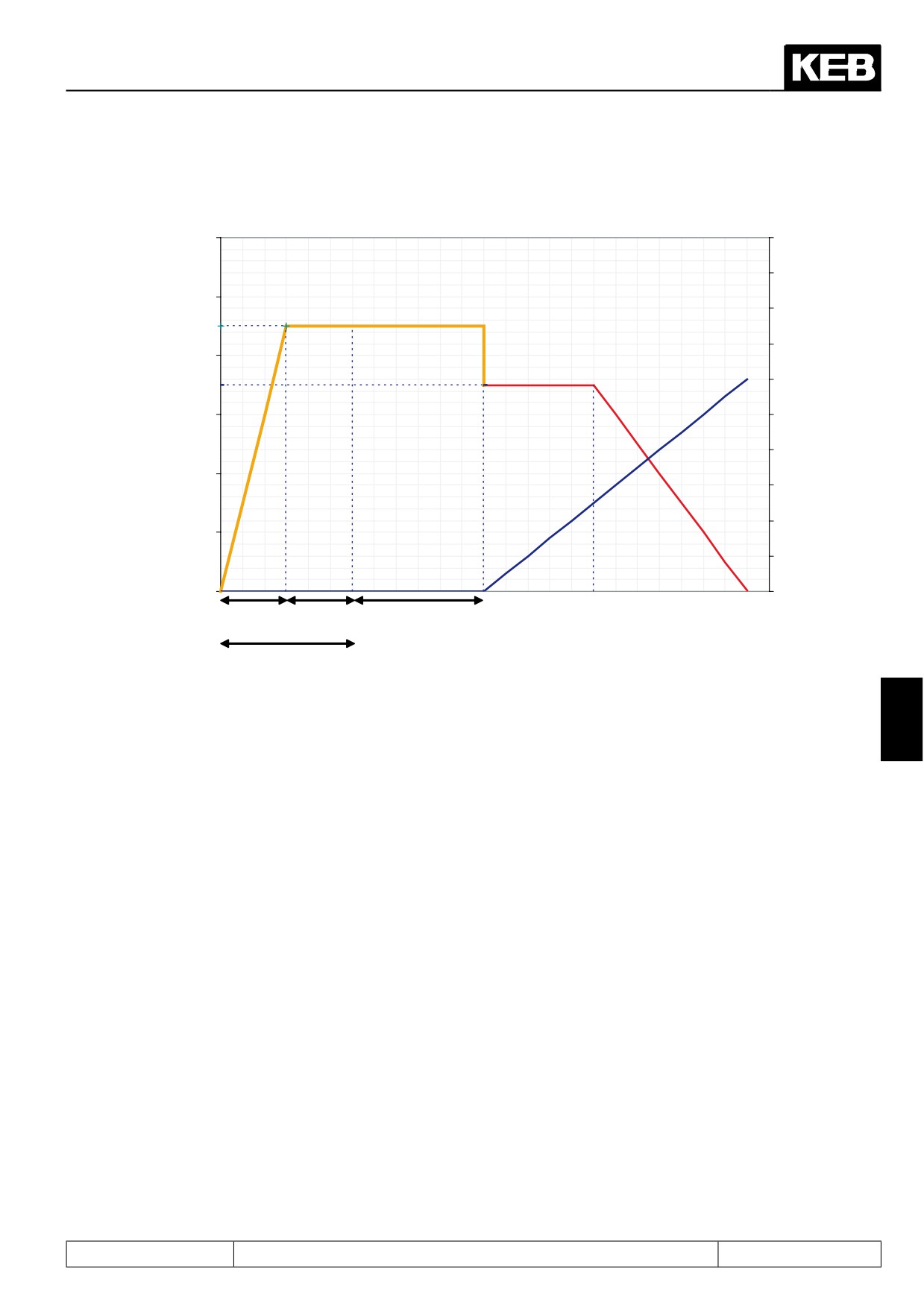
It must be secured that the rotor is in a defined position after switching on of the control release ST. Therefore
a DC current is injected at standstill. Then the rotor rotates into its origin position.
The standstill current is ½ of the rated current and can be adapted in parameter nn.10 in default setting after
operation of Fr.10.
The times (Pn.35 and Pn.36) of the brake handling are active for standstill operation. In order that the rotor
does not vibrate after setting the control release, the current reaches the setpoint value in a half of the time
adjusted in Pn.35 "premagenetising time". (see picture 7.6.3.4a)
The half current-dependent load torque is acceptable as mechanical load (e.g. ¼ of the rated torque at ½ of
rated current at standstill).
Page7.6 - 12
Motor Data and Controller Adjustments of the Synchronous Motor
Picture 7.6.3.4a
Current (A)
Speed (rpm)
12
200
180
10
160
Alignment current
nn.10
140
8
Stabilisation
current
ramp output
120
nn.01
ru.02
6
100
80
4
60
40
2
20
0
0
nn.02
nn.03
½ pn.35
½ pn.35
pn.36
pn.35
Speed search
7
The rotor rotates at some applications when the modulation is switched on. The current speed can be deter-
mined with Pn.26 "speed search condition". (For further information see chapter 7.13.4 SSF)
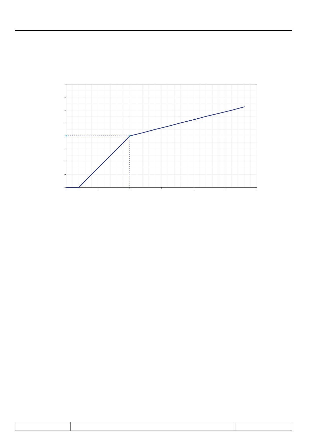
Additional start ramp
In order to leave the critical range of small speed at starting and stopping there is an additional ramp for this
range.
The ramp is defined by parameter nn.08 "start-up speed" which indicates the speed range and parameter nn.09
"start-up time" which indicates the appropriate acceleration-/ deceleration time.
Page7.6 - 13
Motor Data and Controller Adjustments of the Synchronous Motor
Picture 7.6.3.4b
Speed / rpm
160
140
120
100
Ramp output
ru.02
nn.08
80
60
40
20
0
0
0,25
0,5
0,75
1
1,25
1,5
nn.09
Time / s
Example:
Ud.02 = 8: F5S / 4000 rpm
nn.08 = 80 rpm
nn.09 = 6,25
s
Open loop operation/ start ramp
The open loop operation is activated with bit 9 of nn.00 "motor model select" and is only active during
Start ramp is active (Prerequisite: start ramp is parametrised!)
The current of nn.01 "stabilisation current" must be regarded as maximum active current. The current ramp of
nn.02 and nn.03 must be parametrised by such way (see also chapter 7.6.3.5 "Low speed") that the lowering
of current (nn.03) is upside the deactivation of the open loop operation (nn.03 > nn.08).
Page7.6 - 14
Motor Data and Controller Adjustments of the Synchronous Motor
7.6.3.5Low speed
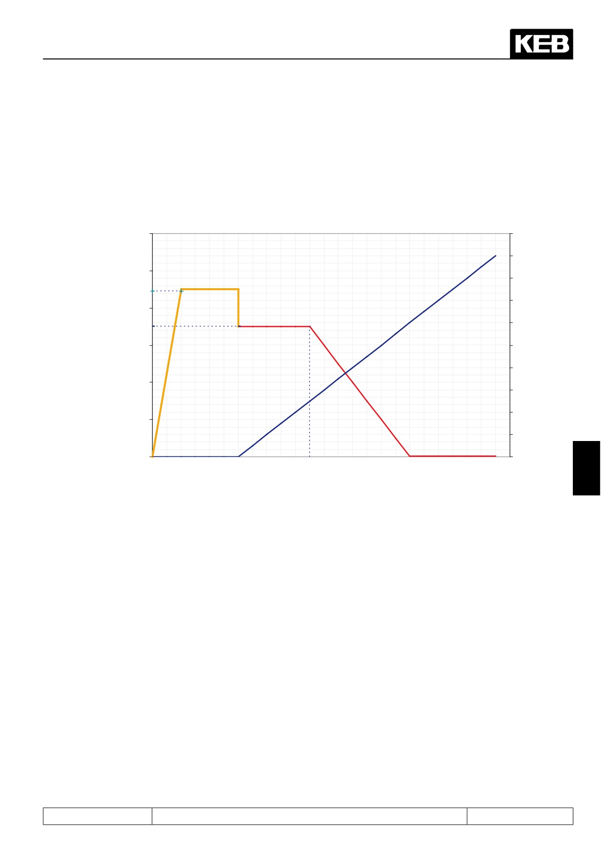
The critical speed range (typically below 1% of the rated speed) is stabilised by reactive current. This current
adjustable in nn.01 "stabilisation current" is linear reduced depending on the actual speed in ru.07 from speed
nn.02 "min speed for current" to nn.03 "max. speed for current".
Picture 7.6.3.5a
Current [A]
Speed [rpm]
12
200
180
10
160
Alignment current
nn.10
140
8
Stabilisation
current
120
nn.01
ramp output
6
100
ru.02
80
4
60
40
2
20
0
0
7
nn.02
nn.03
It is necessary to adapt the current or the ramp if there are vibrations during steady state.
Page7.6 - 15
Motor Data and Controller Adjustments of the Synchronous Motor
7.6.3.6Motor model
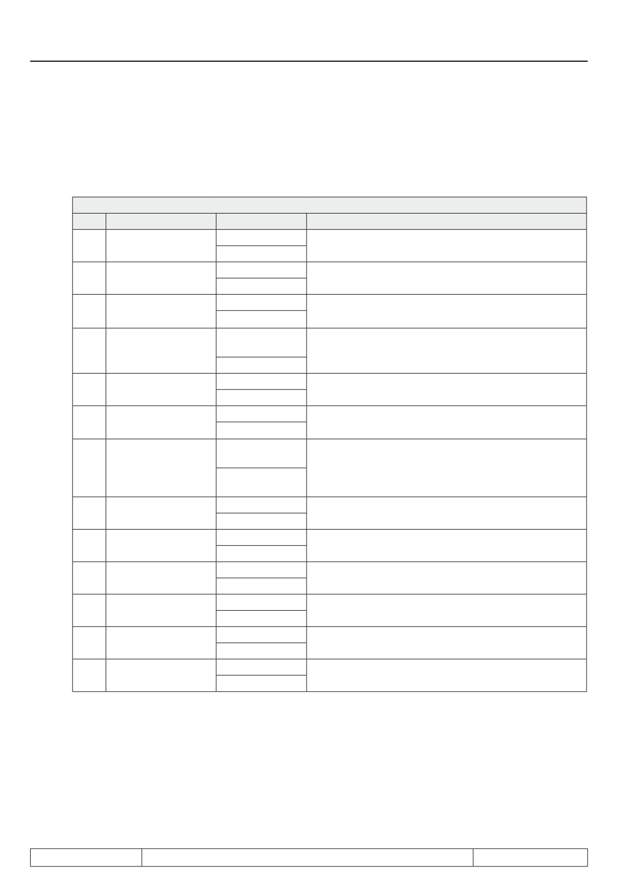
The motor model calculates an estimated speed from the motor data and the actual values of voltage and cur-
rent. Then this speed is admitted to the speed controller. The calculated model currents can be used also for
current control.
nn.00 Motor model select
Bit
Description
Value
Function
Standstill current and
0: off
0
Activation of nn.01 and nn.10
stabilisation current
1: On *
0: off
1
Model stabilisation
Stabilises the motor model
2: On *
0: off
Stator resistance/
2
Adapts the stator resistance at low speed
adaption
4: On *
0: encoder inter-
Speed control with model to encoder 1
3
Speed source
face 1
Speed control with speed estimation
8: Model *
0: off
4
High-speed model
Activates the high-speed model for upper speed
16: On *
Observer/ motor
0: off
5
Stabilises the high-speed model
model
32: On *
0: measured
current *
6
Current control with
Current control to model currents
64: estimated
currents
0: off
7
EMK adaption
Adapts the EMK at upper speed
128: On *
Current offset adap-
0: Off *
8
Adapts the current offset during operation
tion
256: an
0: Off *
9
Controlled operation
Switching off the model during start ramp
512: an
0: Off *
Activates the harmonic absorber for operation with sine-
10
Band-stop filter
1024: an
wave filter
0: Off *
11
Deviation controller
Deviation of model currents to measured currents
2048: an
Voltage output for Hf-
0: Off *
12
Activates double voltage output
applications
4096: an
* Default values
Page7.6 - 16
Motor Data and Controller Adjustments of the Synchronous Motor
Stabilisation current and standstill current (nn.01, nn.10)
The currents nn.01 "stabilisation current" and nn.10 "standstill current" can be switched off with bit 0 of nn.00.
The starting phase with activated currents runs more steady. In such a way this adjustment should not be
changed!
The values are limited to ½ of the HSR current In.18 if the rated motor current is higher than the inverter rated
current.
Stator resistance adaption
The stator resistance changing by temperature influences can affect the behaviour at low speed as well as the
start. The RS adaptation adjusts the stator resistance and stabilises the motor model therefore.
The I-part of the adaptation can be adjusted with nn.06 "rs adaption factor". The rs adaptation becomes active
with ru.17 "active current" > nn.01.
EMK adaption
The EMK changing by load and temperature influences is adjusted at upper speed.
The adaption becomes active at actual speed ru.07 > ¼ of the rated speed dr.24 and improves the accuracy
of the actual torque display ru.12.
Observer
The observer amplifies the influence of the measured currents in the model. The most effects become notice-
able in the upper speed range.
The value must be increased if current oscillations occur at e.g. applications with high frequency.
The observer factor can be adjusted with nn.07 "observer factor".
7
Voltage output for Hf applications
It is necessary for applications with high frequency to activate the double voltage output with bit 12 of nn.00.
Speed estimation
The speed estimate controller is calculated by writing on Fr.10 and cannot be changed. The speed estimate
controller estimates a speed from the currents of the motor model. Parameter nn.04 "time speed calculation"
determines the scan time of the speed estimate controller. This time should not be changed.
Parameter nn.05 "filter speed calculation " determines the smoothing time at the output of the controller. Oscil-
lations are reduced when the value is increased, but the drive becomes more non-dynamic.
At special applications the drive has to rotate only into one-way direction. The respective direction of rotation
can be locked with oP.40/ oP.41 "max. output val. for/rev" by writing the parameter value to "0" and thus the
speed estimation is limited.
The general speed control settings can be set according to chapter 7.7.1. "speed control".
Diagram of the controller structure for operation without encoder feedback, see chapter 7.6.4.
Page7.6 - 17
Motor Data and Controller Adjustments of the Synchronous Motor
7.6.3.7Operation with sine-wave filter
For the operation with sine-wave filter it is necessary to filter the resonance frequency with a band-stop filter.
The resonance frequency of the sine-wave filter and the corresponding filter parameters can be determined
with the tool sine-wave filter.exe. The equivalent circuit data of the motor and sine-wave filter must be entered
in order to generate a parameter list. Then this parameter list must be loaded to the frequency inverter. The filter
parameters are stored in the fh parameter group.
The resonance frequency is filtered of the estimated currents with software filter, in order that there is no reac-
tion. The band-stop filter must be activated in nn.00 "motor model select" bit 10 (band-stop filter). Also it must
be controlled to the estimated currents nn.00 bit 6 (current control). The deviation controller should be switched
on with bit 11 of nn.00 in order to avoid possible effects on wrong estimation. The deviation controller adjusts
the estimated currents to the measured currents with the scan time of nn.12 "deviation control time". This time
can be increased in case of current oscillations.
The inverter current is mostly higher than the motor current because there is a current flow through the capa-
citor of the sine-wave filter. The single-phase capacitor value must be entered in nn.13 "C-filter [UF]" in order
to clear this error.
The EMK adaptation must be deactivated with bit 7 of nn.00.
The increased current ripple and the capacitor current must be considered at the dimensioning of
the inverter!
Page7.6 - 18
Motor Data and Controller Adjustments of the Synchronous Motor
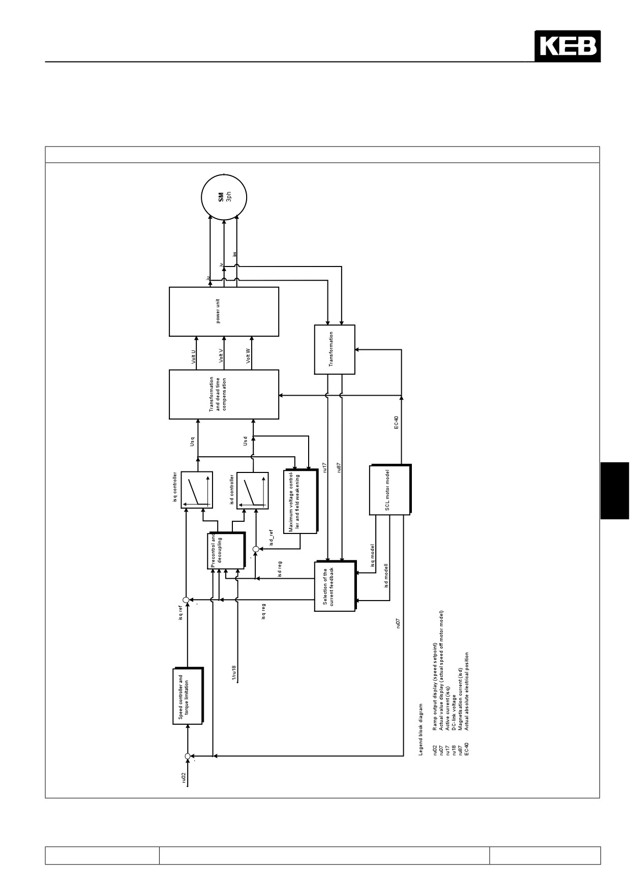
7.6.4
Block diagram
Figure 7.6.4.a Block diagram SCL
7
Page7.6 - 19
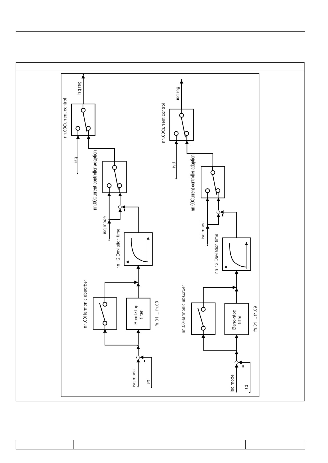
Motor Data and Controller Adjustments of the Synchronous Motor
Figure 7.6.4.b SCL Current feedback
Page7.6 - 20
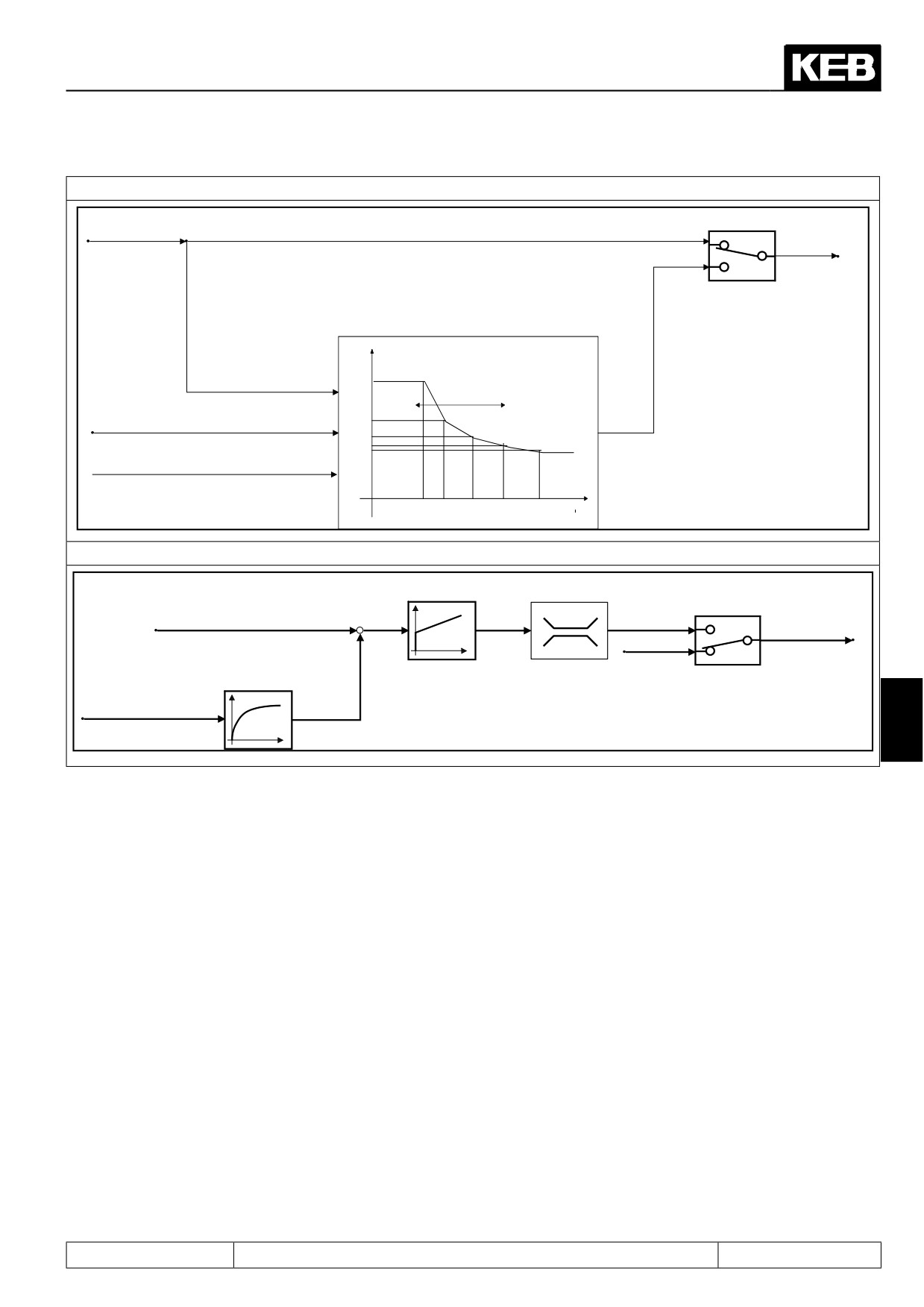
Motor Data and Controller Adjustments of the Synchronous Motor
Figure 7.6.4.c Torque limitation field weakening
ds03.Torque mode
isq_ref_int_c
off
isq_ref_int_c
on
Torque limit characteristic for field weakening
(only further reduction of the limits)
M
dr.33
ds03.UZK depending shifting
nist
dr.40
dr.42
dr.44
dr.46
Uzk
n
dr.39
dr.41
dr.43
dr.45
dr.47
Figure 7.6.4.d Field weakening
ds.08 KP Umax.
ds.13 Magn.
ds.09 Ki Umax.
current limit
ds.04Maximum voltage controller
ds.10 Umax modulation ref.
on
isd_ref
-
0
off
-ds.13 ... 0
1ms
ru.42 Modulation grade
7
Page7.6 - 21
Motor Data and Controller Adjustments of the Synchronous Motor
Page7.6 - 22
Speed Control
7.1
Operating and appliance date
1.
Introduction
7.2
Analog in- and outputs I
2.
Summary
7.3
Digital in- and outputs
3.
Hardware
7.4
Setpoint-, rotation- and ramp adjustment
Motor data and controller adjustments of the asynchronous
7.5
4.
Operation
motor
Motor data and controller adjustments of the synchronous
7.6
motor
Selection of Operating
5.
Mode
7.7
Speed control
6.
Initial Start-up
7.8
Torque display and -limiting
7.9
Torque control
7.
Functions
7
7.10
Current control, -limiting and switching frequencies
8.
Error Assistance
7.11
Speed measurement
9.
Project Design
7.12
Positioning and synchronous control
7.13
Protective functions
10. Networks
7.14
Parameter sets
11. Parameter Overview
7.15
Special functions
12. Annex
7.16
CP-Parameter definition
Page7.7 - 1
Speed Control
7.7.1.
Speed controller parameters
7.7 - 3
7.7.1.1
Basic settings
7.7 - 3
7.7.1.2
Automatically adjustment of the speed controller
(only at the operation with motor model)
7.7 - 3
7.7.1.3
Operating condition dependent control parameters
7.7 - 4
7.7.2.
Determination of the mass moment of inertia
7.7 - 5
7.7.3.
PT1 output filter
7.7 - 6
7.7.4.
Acceleration dependent pre-control
7.7 - 6
7.7.4.1
Precontrol reach-through / smoothing
7.7 - 7
7.7.4.2
Setpoint smoothening
7.7 - 7
Page7.7 - 2
Speed Control
7.7
Speed control
The speed controller is a PI controller.
A PT1 low pass filter is series-connected.
The integral factor Ki can be changed speed-dependent. The proportional factor Kp can be increased propor-
tionally to the control deviation.
In order to improve the control performance of the drive (low overshoot, higher dynamics), the speed controller
can be pre-controlled with known mass-moment of inertia.
7.7.1. Speed controller parameters
7.7.1.1Basic settings
The speed controller is a PI controller.
The proportional factor "Kp speed" is adjusted in cS.06 and the integral factor "KI speed" in cS.09.
7.7.1.2Automatically adjustment of the speed controller (only at the operation with motor model)
Kp (cS.06) and Ki (cS.09) of the speed controller can be preset by the inverter. For this the mass-moment of
inertia of the complete system (motor + rigidly coupled load) must be entered in cS.25 "inertia".
After input of the motor data parameter Fr.10 "Load motor dependent parameter" must be written once to 1
or 2. Thus dependent on the adjusted rated power (dr.03) the mass-moment of inertia was pre-charged for a
standard asynchronous motor in cS.25. The value of cS.25 has the right dimension for 50Hz standard motors,
because at some applications the ratio of the load inertia is in a range of 0,5..2 x motor inertia.
Better results can be realized, if the total moment of inertia is exactly preset. If the value is unknown it can be
determined.as described in chapter 7.7.2.
7
Parameter cS.26 "optimisation" determines the control characteristic which should be achieved by the calcu-
lated parameters.
Parameters for a dynamic, hard speed controller adjustment are calculated.with cS.26 = 2. Disturbances like
e.g. torsion or clearance of the load coupling can increase oscilallations, thus a higher value must be entered
in cS.26.
Parameters for a soft and slow speed controller adjustment are calculated.with cS.26 = 15. Which value bet-
ween 2 and 15 is most suitable for the application is depending on the oscillation-grade of the total system.
An oscillation of the estimated speed is a possible disturbance at encoderless operation of asynchronous
motors (ASCL). Extension of parameter "Speed PT1 time ASCL" (ds.17) often enables a dynamic speed con-
troller adjustment, i.e. a smaller value for cS.26.
Precharging of speed controller parameters can be deactivated with the adjustment of value „19 = Off" in
cS.26.
The speed controller parameters are overwritten when the value for cS.26 is changed.
Page7.7 - 3
Speed Control
7.7.1.3Operating condition dependent control parameters
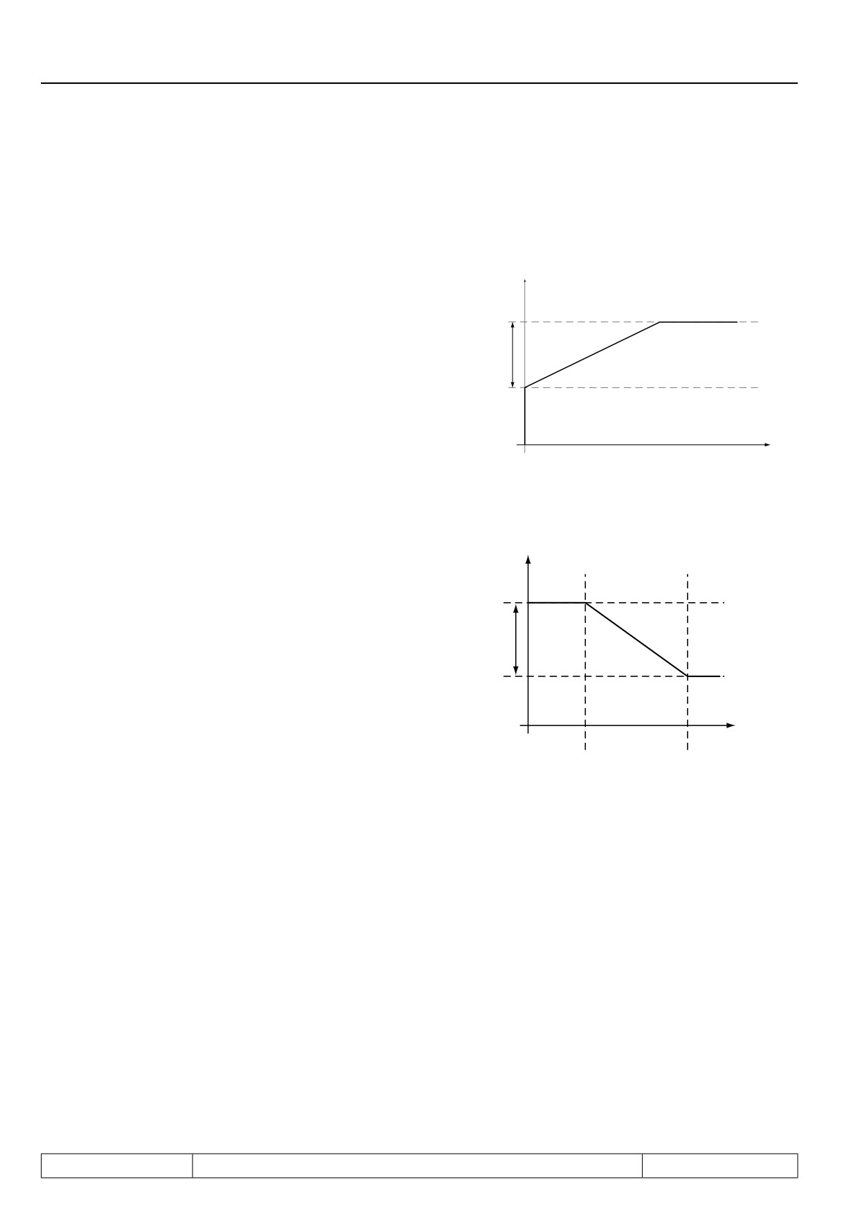
The following parameters serve for the "fine tuning" of the speed controller and are not required in many appli-
cations.
variable proportional factor Kp
KP factor
The proportional factor "KP speed" is adjusted
in cS.06.
In addition to the standard KP value a system-
cs.08
deviation-dependent proportional gain can
be adjusted with cS.07 and cS.08. With it the
dynamic performance can be improved and
overshootings can be dampened.
cS:08
Xd(n)
variable integral factor Ki
KI factor
Parameters cS.09...cS.12 determine the inte-
gral factor of the speed controller.
The KI-factor can be varied speed-dependent in
order to reach a better speed rigidity at small
cS.09
speeds and in standstill.
- cS.09 forms the base value
- the maximum value for the integral factor
cS.09+
is cS.09 + cS.10
cS. 10
- the two corner speeds cS.11 and
cS.12 determine the speed range in which the
KI value is changed
cS.11
cS.12 act. speed
A special function can be activated in parameter max. speed for max. KI (CS.11) by setting -1: brake release
which works only in connection with the brake control.
An enormous speed rigidity is required for load transfer with hoist drives or lifts,
in order that the brake release and the load transfer are not significant by the inverter.
This controller adjustment is not to be used for normal operation, since the speed controller oscillates too much
at this adjustment.
The solution is to enter a high value in parameter "KI offset“ (cS.10) in order make the controller rigidy. If CS.11
indicates the value „-1: brake release ", this "KI offset " is set immediately to 0 at the end of the brake release
time, not reduced during operating in a speed range.
Page7.7 - 4
Speed Control
7.7.2. Determination of the mass moment of inertia
The knowledge of the mass moment of inertia of the system (motor + rigidly coupled load) is required for the au-
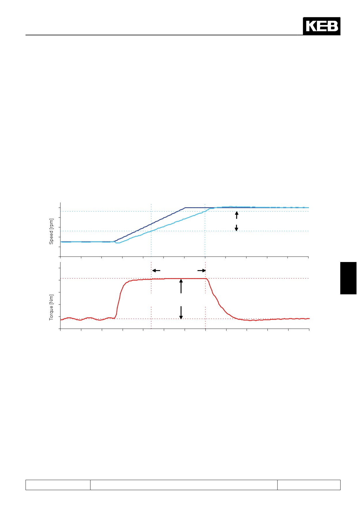
tomatic calculation of the speed controller parameters as well as for the pre-control of the acceleration torque.
If this mass moment of inertia is unknown, it can be determined by an acceleration test.
For this the system must be accelerated with defined, constant torque. It must be guaranteed that no significant
and acceleration-independent load torque occurs by the application.
The following formula is valid:
∆t
J = 95493 x ∆M x
———
∆n
Example: The following acceleration was recorded with Combivis:
Acceleration test for detection of the mass moment of inertia
Set speed
delta n = 402 1/min
Calculated actual speed
delta t = 0,26s
7
Acceleration torque
delta M = 662Nm
Time [s]
0,26 s
J = 95493 x 662 Nm
——————
= 40886 kgcm2
402 rpm
In order to eliminate the influence of friction from the calculation, the moment of inertia can be determined a se-
cond time in a similar manner, however by a delay test. The average value of both inertias, which is determined
at run-up or deceleration must be entered in parameter cS.25 „inertia (kg cm^2)“.
Page7.7 - 5
Speed Control
7.7.3. PT1 output filter
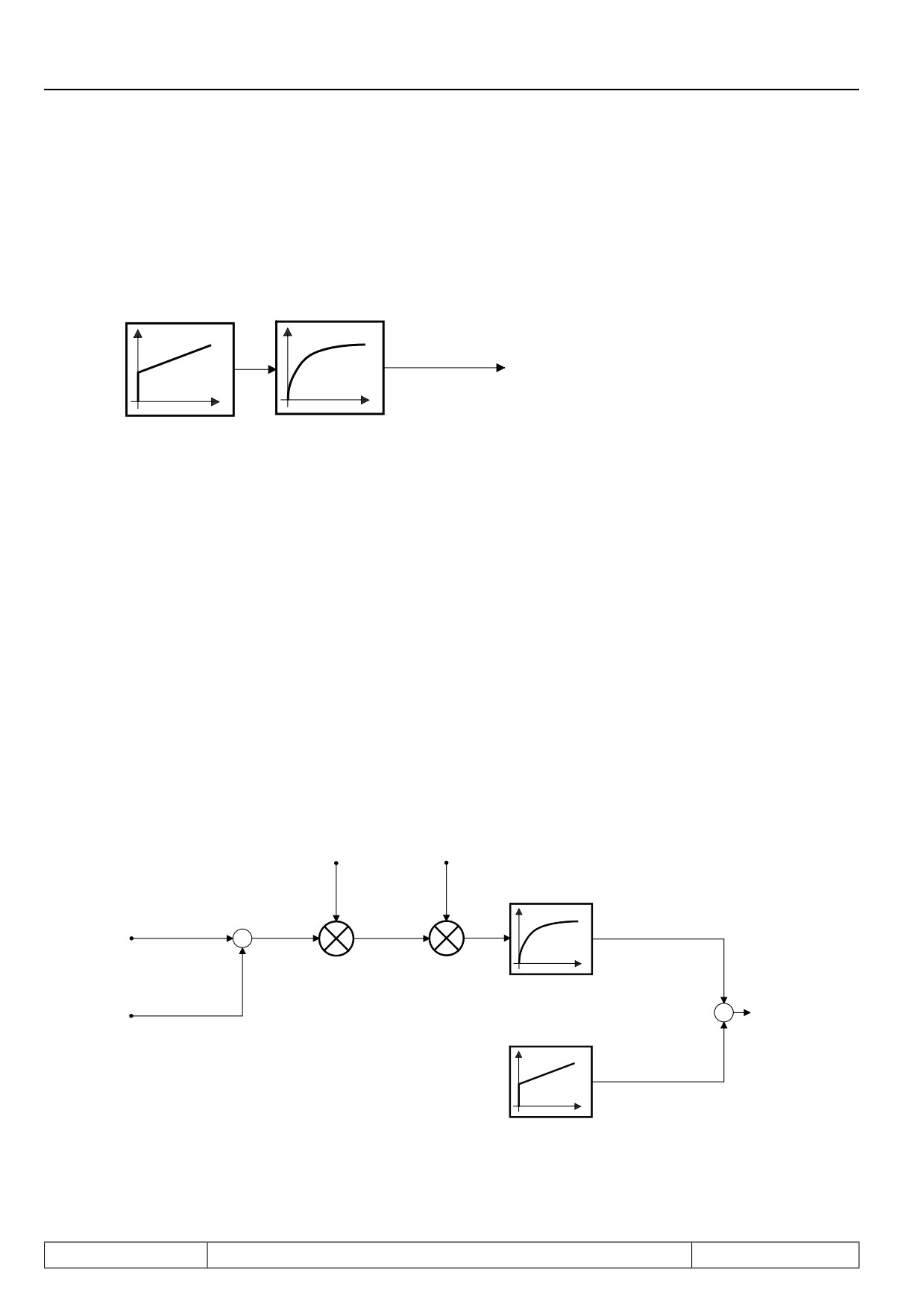
A PT1 low pass filter is series-connected to the speed controller.
Figure 7.7.3 PT1 Output filter
Speed controller
Low pass filter
Active current setpoint
PT1
cS.06...cS.12
cS.29
High frequency oscillations (caused by spring elements in the mechanics of the drive train) can be filtered by
this way from the active current setpoint signal.
The filter time must be adjusted in parameter „act. curr. ref. PT1-time“ (cS.29). A longer filter time causes a
stronger smoothing of the active current signal, but also less dynamic control characteristic and increased
oscillation inclination.
Adaption of the speed controlller is necessary when changing the Pt1 time. This filter is used e.g. for spindles,
in order to avoid step changes at fast load changes in the current setpoint.
7.7.4. Acceleration dependent pre-control
If the mass moment of inertia of a drive is known it can be calculated which torque is required to accelerate the
drive. This function is activated, if a value unequal 0 is entered in parameter "pretorq. speed fact.%" (cS.28).
This parameter must be set to 100% for a complete pre-control.
Picture 7.7.4 Acceleration dependent pre-control
Pre-torque speed
Inertia (kg*cm^2)
factor %
(CS.25)
CS.28
Low pass filter
Actual setpoint
Pre-controlled
speed
+
delta n_set
acceleration torque
-
PT1
Pre-torque speed
Setpoint speed
PT1-time filter (CS.27)
+
pre 1ms
+
Speed controller
Page7.7 - 6
Speed Control
7.7.4.1Precontrol reach-through / smoothing
For some applications it is not necessary to pre-control the complete acceleration torque (cS.28 = 100%) see
the following reasons:
-
a different torque is required with the same acceleration at motoring or generating (e.g. due to fric-
tion)
-
the speed setpoint setting (e.g. by external control) is made in steps, so torque jumps would occur
-
the (analog) speed setpoint setting is superimposed by a noise, which must be damped for the pre-
control
The influence of the pre-control can be damped with parameter "pretorq. speed fact. %" (cS.28) for these ap-
plications.
Torque peaks, which are caused by a speed setpoint setting in steps, can be reduced by means of a low pass
filter. At a higher time in parameter "pretorq. speed PT1- time" (CS.27) the smoothing is better, but the pre-
control is more non-dynamic.
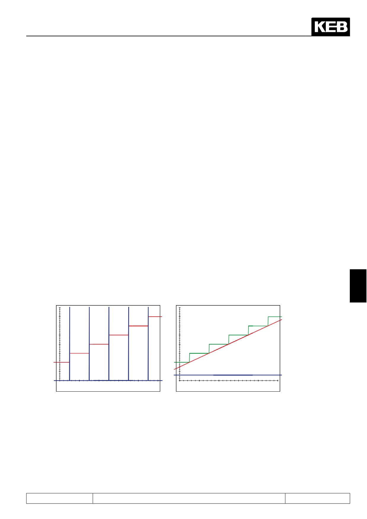
7.7.4.2Setpoint smoothening
For applications, when new setpoints are preset by an external control within fixed time base there is one addi-
tional function for the acceleration torque precontrol: the reference splitting.
without reference splitting
with optimal reference splitting
(Parameter oP.74 „reference splitting“ = 0:
(Parameter oP.74 „reference splitting“ =
off)
cycle time of external reference setting in
A high control value is calculated at every
ms).
new setpoint step without reference split-
The speed setpoint is smoothed, the pre-
7
ting. The pre-control function cannot be
control value remains constant.
used.
Setpoint setting of
external control = setpoint
Setpoint setting of
speed before ramp
external control
Setpoint speed
before ramp (ru.01)
Pre-control value for the
acceleration torque
Pre-control value for the
acceleration torque
Time [ms]
Time [ms]
Page7.7 - 7