KEB COMBIVERT F5-A,-E,-H 4.0. APPLICATION MANUAL (2008) - page 10
Motor Data and Controller Adjustments of the Asynchronous Motor
The parametrisation of the controller (KP flux / dS.11, KI flux / dS.12, magnetising current limit/ dS.13) is carried
out automatically by Fr.10 and after the motor identification (dr.48).
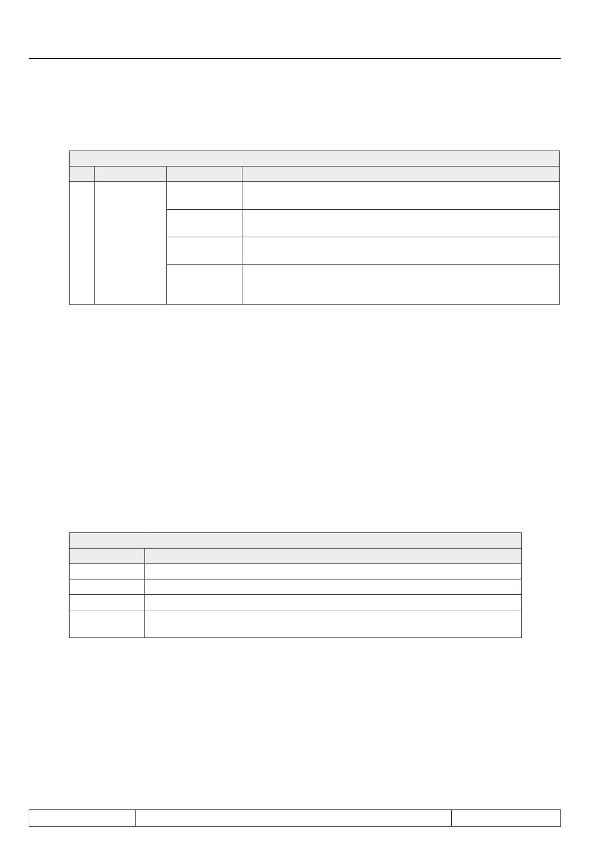
dS.04 Flux / rotor adaption mode
Bit
Meaning
Value
Explanation
Flux controller always off (these adjustment is not allowed for the ope-
0: off
ration with motor model)
flux controller always on (must be used for control with motor model
32: on
and encoder feedback)
Flux control
5,6
64:on,
flux controller active, speed-dependent limit of the controller (at speed
(ASM)
n^3/dr.17^3
0 = 0 / at speed dr.17 = dS.13)
as value 64, exception: start of the drive:
96:on, start a.
here, (despite speed 0) the limit of the flux controller is set to the value
n^3/dr.17^3
dS.13 for the magnetisation.
During operation with speed feedback, the flux controller must be activated over the whole speed range, i.e.,
the value 32 must be chosen in dS.04 in the item "flux control" .
During operation without speed feedback, the value 64 or 96 should be selected.
With Fr.10, the parameter dS.13 "Magnetising current limit" is set to half the rated motor current. If the flux build-
up time is to be shortened or if particularly high demands are made on the dynamics in the field weakening
range, this value can be changed to the rated motor current (dr.00).
The inverter can only provide the standstill current at speed 0. Error OL2 is released shortly if the current is
higher. Thereby this can lead to problems during magnetizing at some motor/inverter combinations. In these
cases, the setting dS.04 Bit 5, 6 = 64 "flux controller not active during boot" must be chosen.
7.5.2.3.3.1
Dead time compensation
The drive has also measured the dead time compensation characteristic during automatic identification. The
calibrated characteristic must be activated for the control with motor model by the setting "dead time compen-
sation mode" (uF.18) = 3: "automatic".
uF.18 Dead time compensation mode
Value
Explanation
0: off
Deactivates the dead time compensation
1: linear
Default setting for u/F characteristics open loop operation
2: e function
Only required for special applications
3: automatical-
Activation of the identified characteristic. Shall always be used at control of asyn-
ly
chronous motors with motor model
Further available kinds of the dead time compensation are only required for special applications (applications
with high frequencies, some special motors) or in other operating modes (e.g. V/f characteristics controlled).
The dead time compensation can be switched off via a digital input. The digital input is selected with parameter
uF.21. This disconnection is only required for special applications with high frequency.
Page7.5 - 22
Motor Data and Controller Adjustments of the Asynchronous Motor
7.5.2.3.4
Magnetisation current adaption / with motor model
For large motors, the automatic calculation of the magnetising current occasionally returns values that are too
large. This way, the dynamic operation in the field weakening range may worsen.
Whether the automatically calculated magnetising current is too large, can be tested by accelerating the drive to
the field weakening speed (dr.18) with no load. At this speed, the voltage limit (modulation factor 100%) should
not be reached yet. Otherwise, the "factor flux adaption" (dr.19) should be reduced.
Since a new identification of the main inductance must be carried out (dr.48 = 6) after the modification of these
parameter, the "flux adaption factor" (dr.19) should be reduced until the modulation factor is approx. 90 - 95%.
Subsequently, a new identification of the main inductance must be carried out (dr.48 = 6) and, with dr.48 = 5,
the controller must be adapted to the new main inductance.
The new "flux adaption factor" must then be checked with a new ramp-up.
Attention: If the factor is reduced too much, the available voltage will not be fully exploited anymore (modulation
grade ru.42 even for high speed and a load always smaller than 95%), and the motor current increases!
7.5.2.4Vector control without speed feedback (ASCL)
This chapter must be read only if an asynchronous motor without speed feedback is to be operated. Since the
speed can be calculated only with the aid of a mathematical model, this operating mode may only be used with
the following limitations:
-
Vector control around frequency = 0 is not possible.
-
During operation in the low speed range, the motor model may become unstable, this range, therefore,
must always be left quickly.
-
No safety functions may be derived from the calculated speed
This operating mode is only available through auxilliary software F5H-M.
7
For the motor model, there are some additional parameter for adapting the encoderless vector control to the
application.
Operation without speed feedback is activated by cS.01 = 2 "calculated actual value".
In parameter cS.00 "controller configuration", the value 4 "speed control" or 5 and 6, "torque control", respec-
tively, must be set.
7.5.2.4.1
ASCL / low speed operation
Operation at small speed is a critical range which should be passed very fast.
The size of this range cannot be indicated universally valid. It is strongly dependent on the used motors.
The usable speed range for standard-asynchronous motors is approx.:
Power
mot. operation
gen. operation
2,2 kW
1 : 50
1 : 20
85 kW
1 : 100
1 : 50
Start-up speed and start-up time (dS.21 / dS.22)
In order to leave the critical range of small speed at starting and stopping there is an additional ramp for this
range.
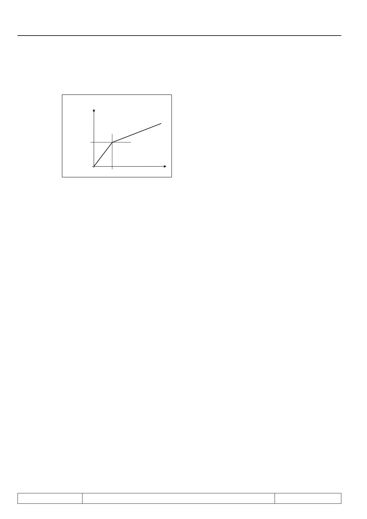
The ramps is defined by parameter dS.21 "start-up speed" and dS.22 "start-up time".
Page7.5 - 23
Motor Data and Controller Adjustments of the Asynchronous Motor
The parameter dS.21 indicates the speed range for which the start ramp applies. dS.22 indicates the accele-
ration-/ deceleration time.
Ramp output display
(ru.02)
Example:
ud.02 = 4 (4000 rpm mode)
dS.21 = 200 rpm
200 min-1
dS.22 = 1s
0,2 s
Time
ASCL model shutoff during deceleration (dS.19, dS.20)
If the drive is to be stopped, the critical range of low frequencies must be traversed again.
The additional problem of the drive not stopping completely, but instead running permanently at a low frequency
with a very high current occurs here, leading to a miscalculation of the speed.
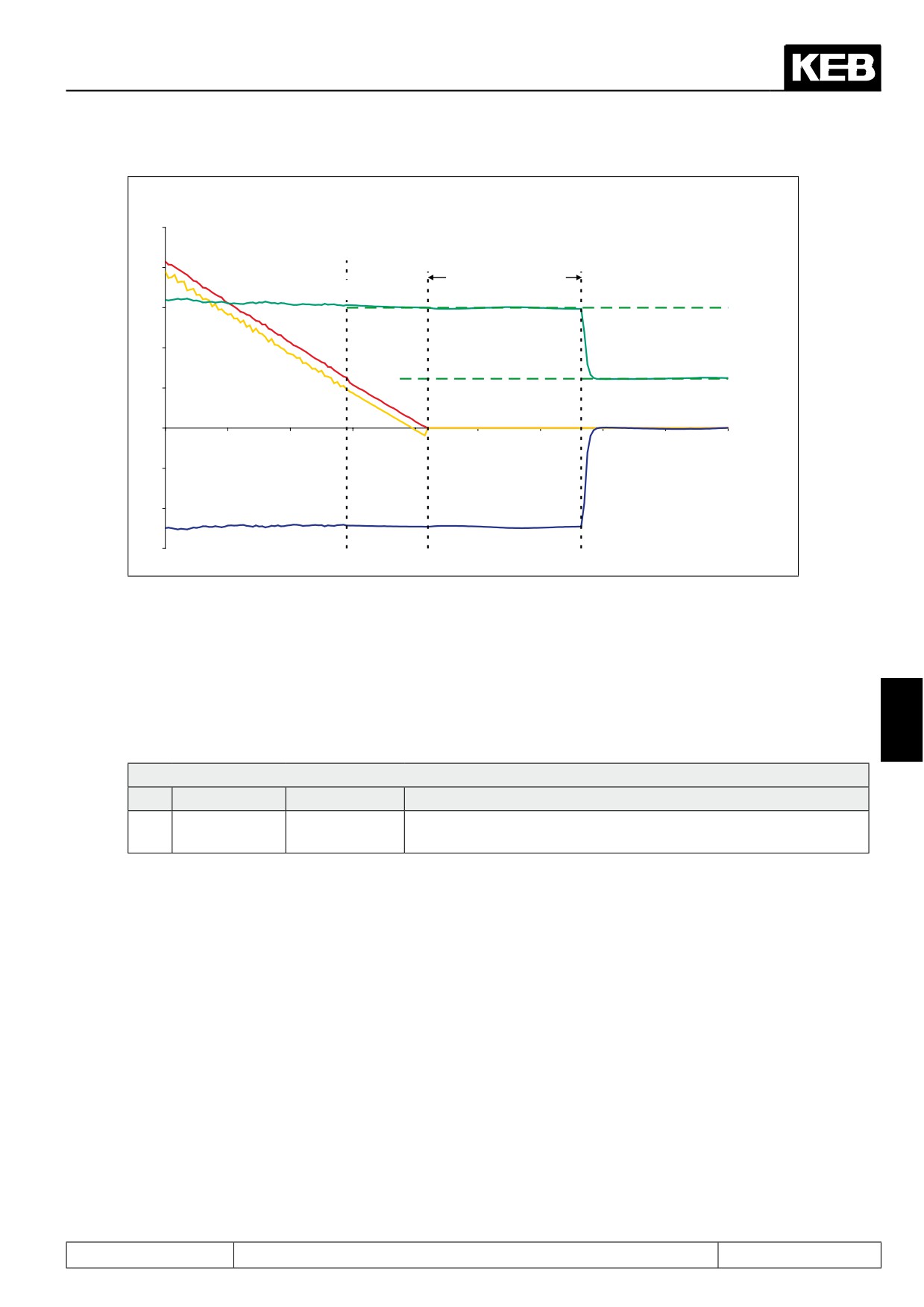
Under the following conditions, therefore, the mode is switched from vector controlled to current regulated,
frequency controlled operation:
- Drive decelerates
- the estimated output frequency is smaller than dS.19 ("limit uf-control dec ASCL")
The drive then shows the following behaviour:
- the output frequency is ramped down according to the adjusted deceleration ramp
- the current is held constant from the switching time on
The parameter dS.19 is loaded with a default value by the identification or by Fr.10 "Load mot. dependent pa-
rameter". Should problems still occur during deceleration, the value for dS.19 can be increased.
If the drive is stopped by switching off the rotation direction release, the modulation is switched off after rea-
ching output frequency 0.
If the drive is stopped by setting the setpoint to 0, the current is reduced to the magnetising current after rea-
ching the output frequency = 0.
At this point, the real speed of the motor is not yet 0 in some cases.
Therefore, the time for which the higher constant current is set can be increased with parameter dS.20 "delay
time uf-control".
Page7.5 - 24
Motor Data and Controller Adjustments of the Asynchronous Motor
ds.19: limit uf-control
deceleration ASCL
=> switching into
frequency-controlled
operation
ds.20: ASCL
delay time
Apparent current (ru.15)
uf-control
Overshoot current
Actual speed (ru.07)
Frequency (ru.03)
Magnetizing current
Time [ms]
Actual torque display (ru.12)
Attention: The actual torque display (ru.12) is invalid after switching to the frequency controlled operation!
ASCL / reversing
If one wants to run the drive through zero speed without stopping to change (reverse) the direction of rotation,
switching to the frequency controlled mode can be disruptive.
7
Therefore, this switching can be deactivated by setting bit 2 in parameter "function mode" (dS.18).
dS.18 Function mode
Bit
Meaning
Value
Explanation
Model switch-
0: activated
Deactivate switching to the frequency driven, current-controlled
2
off
4: deactivated
operation
To utilise the open loop mode for stopping, but, on the other hand, avoid negative effects during reversal, the
inverter must be programmed so that stopping of the motor always follows in the same set.
Then, one can let the switch to the open loop mode be activated for this set (the stop-set) (dS.18 = 0), and avoid
interfering effects during reversal for other sets with dS.18 = 4.
The, it is only necessary to ascertain that the range of low frequencies is traversed quickly.
This can be achieved by suitably setting parameter "start-up time" (dS.22) and parameter "start-up speed"
(dS.21), which apply to acceleration as well as deceleration.
ASCL / constant run with low speeds
Speed setpoints lying within the critical range must be avoided.
To avoid continuous operation in low frequency range, the minimum setpoint (oP.06 / oP.07) should be set to
speeds outside the critical range.
Alternatively, too-small setpoints may also be masked by parameter oP.65...oP.68 (blocked setpoints).
Page7.5 - 25
Motor Data and Controller Adjustments of the Asynchronous Motor
7.5.2.4.2
Switch to consecutive motor
If the motor is still rotating during addition of the modulation (e.g., "rundown" after malfunction), the calculation
of the actual speed from the motor model can become unstable.
Therefore, if there is a risk that the motor has not reached speed 0 for the start, there are two alternative starting
methods:
Speed search condition (Pn.26) or DC braking (Pn.28 / Pn.33)
During speed search, the drive attempts to determine the current speed via its mathematical model. The ope-
ration corresponding to the setpoint settings is re-established starting at this speed. For many standard motors,
this type of addition can be used.
For some motors or applications, e.g., for spindles, application of the speed search will be unsuccessful. In
these cases, speed is calculated incorrectly, the drive can vibrate, or the inverter can malfunction.
In these cases, the motor must be stopped by DC braking before the drive can be restarted. During DC braking,
a DC voltage is connected to the motor´s clamps. The small braking torque while the motor is still running at
high speed is a disadvantage.
For more (appropriate parameters, settings, etc.) see in 7.13.4 speed search and 7.15.1 DC braking, respec-
tively.
7.5.2.4.3
Model adaption
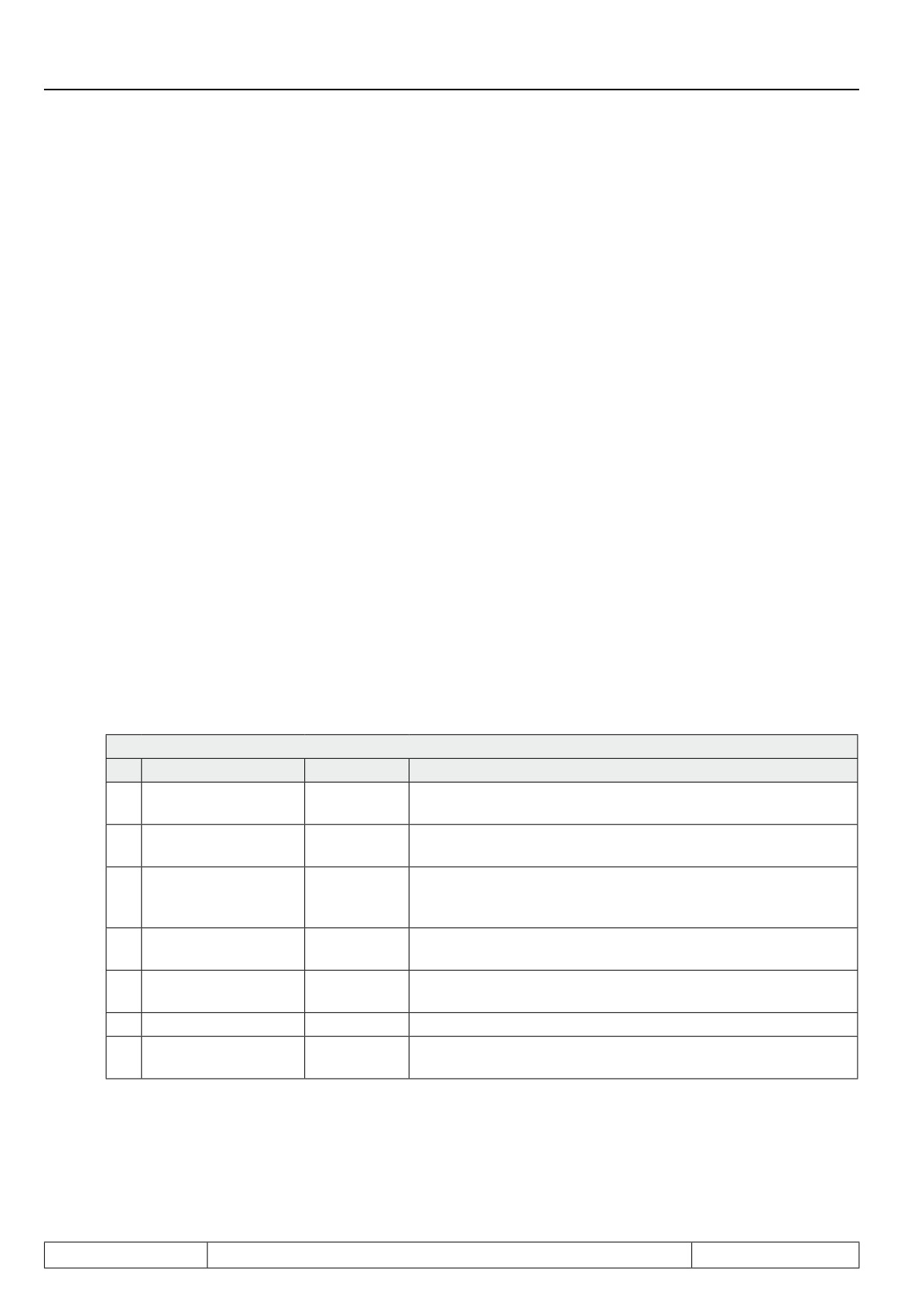
Some auxilliary functions can be activated via the parameter dS.18.
Adjustment of this parameter is not necessary and should only be carried out by authorised KEB service per-
sonnel.
Value 4 is an exception: Model deactivation (see "ASCL model deactivation during deceleration" / subsection
"reversal"). This chapter can therefore be skipped and reading continued in 7.5.2.4.4 "parametrisation of the
speed estimation control".
dS.18 Function mode
Bit
Meaning
Value
Explanation
Current offset/
0: off
0
activates a permanent current offset adjustment
Adaption
1: on
Stator resistance/ ad-
0: off
activates setpoint tracing of the stator resistance, which may
1
aption
2: on
change during operation due to temperature effects
0: activated
Switching in the frequency controlled, current regulated operati-
2
Model switch-off
4: deactiva-
on during stopping
ted
0: measured
Selection of the actual value source of the current controller: 0:
3
Current control
8: calculated
measured current 8: current calculated from the model
Observer /
0: off
4
Activation of an observer for high frequency applications
Motor model
6: on
5
reserved
Voltage output for Hf-
0: off
Activation of a faster voltage output. Only important for high fre-
6
applications
64: on
quency applications
Page7.5 - 26
Motor Data and Controller Adjustments of the Asynchronous Motor
Current offset / adaption
In some cases, the one-time current offset measurement (either with modulation switched off or via test signals
during motor identification) is insufficient since operation-dependent effects (like temperature) are not consi-
dered. With this "residual offset", a vibration is created with a frequency equal to the output frequency. The
current offset adaption can reduce this effect.
Attention: Is the simple vibration not caused by the current offset, the adaption is behaving incorrectly. There-
fore, this function must be activated with caution, or only to prove a current offset exists and to utilise its value.
The adapted current offset can be read off via In.20 = 30, 31 in In.21.
Stator resistance/ adaption
The stator resistance can stabilise the model at low output frequencies, particularly in generatoric operation.
At low motor rating, the effect of the stator resistance in this range is quite large. Due to the motor warming,
changes of up to 40% compared to the resistance calibrated in the cold state are possible. The stator resistance
adaption can compensate for this change.
Under certain operating conditions, (e.g., high dynamic) the adaption diminishes the operational performance
of the drive. Therefore, this function should only be activated when problems with breaking and stopping may
occur for motors with small power (< 5 kW).
Current control by measured / calculated currents
For the current control, either the measured currents or those calculated from the model can be used as actual
values. As a standard, the measured currents are used for control since only this assures direct control over
the real currents.
Using the calculated currents is advantageous only in high frequency applications: The delay (detection of the
actual current until the output of the voltages as response to the current measurement) is noticeable in these
applications. For control based on calculated current, this time is minimised.
7
Observer / motor model, observer effect / motor model
The observer causes an equalisation between the measured currents and the currents calculated from the
motor model. This is useful for some high frequency applications.
The reciprocal of amplification of the observer is set with the parameter "observer factor" (ds.23).
Voltage output for Hf applications
At high output frequencies, the voltage vector must be calculated and output in a shorter time pattern. This is
possible only at 8 and 16 kHz. Important for high frequency applications
7.5.2.4.4
Speed calc. ASCL (dS.14, 15) and speed PT1-time ASCL (dS.17)
Page7.5 - 27
Motor Data and Controller Adjustments of the Asynchronous Motor
The KP (dS.14) and the KI (dS.15) of the speed calculation controller are calculated automatically during the
identification of the motor parameters and may not be changed.
Only the parameter dS.17 "Speed PT1 time ASCL" can be adapted to a specific application. In non-dynamic
applications, a higher PT1 time (up to 32ms for large motors) leads to a steadier calculated speed, without
degradation of the control characteristics of the drive.
In contrast, a lower speed frequently permits a more dynamic setting of the speed control parameters.
If parameter dS.17 "Speed PT1 time ASCL" is changed, a previously conducted adaption of the speed control-
ler must be checked.
If the automatic calculation of the speed control parameters is used, it must be reactivated.
7.5.2.5Special function: Rotor adaption
In speed control with speed feedback, the motor model can be used to adapt the rotor time constant. The rotor
time constant is dependent on the rotor resistance, among others. Due to the temperature change of the motor
rotor, the rotor resistance can change significantly compared to the identified value. This also changes the rotor
time constant. This change leads to a less accurate torque display and an inferior performance of the drive.
The rotor adaption compensates for the temperature deviations of the resistance. It is activated by bit 1 in pa-
rameters dS.04 "Flux / rotor adaption mode".
dS.04 Flux / rotor adaption mode
Bit
Meaning
Value
Explanation
Rotor
adaption
0: off
1
Activation of the rotor adaption
(ASM)
2: on
Rotor adaption/
0: no
Storage of the last rotor adaption value obtained during ope-
2
store (ASM)
4: yes
ration
Bit 2 determines whether the drive stores the rotor adaption value on modulation switch-off. If memory is acti-
vated (memory: yes), the inverter starts with the last value obtained during operation, after reactivation of the
modulation. If memory is deactivated (memory: no), the inverter starts with the value 100%. After"net on",the
inverter always starts with the value 100%.
In parameter ru.59 "rotor adaption factor", the status of the rotor adaption can be read: 100% means that the
drive is working with the identified values.
Page7.5 - 28
Motor Data and Controller Adjustments of the Asynchronous Motor
7.5.3
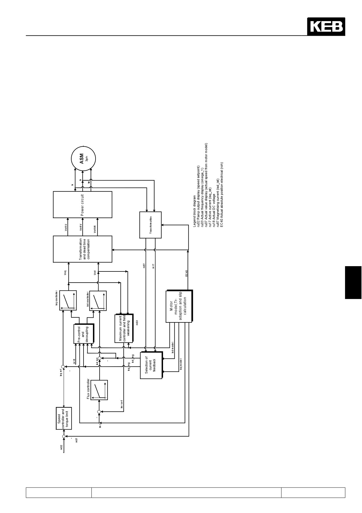
Block diagram
Figure 7.5.3.a Block diagram ASCL
7
Page7.5 - 29
Motor Data and Controller Adjustments of the Asynchronous Motor
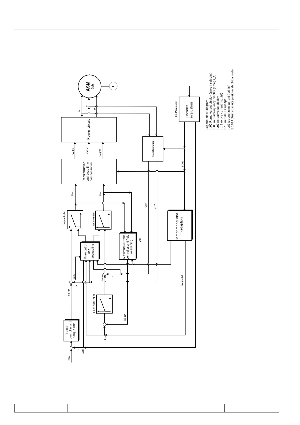
Figure 7.5.3.b Block diagram M
Page7.5 - 30
Motor Data and Controller Adjustments of the Asynchronous Motor
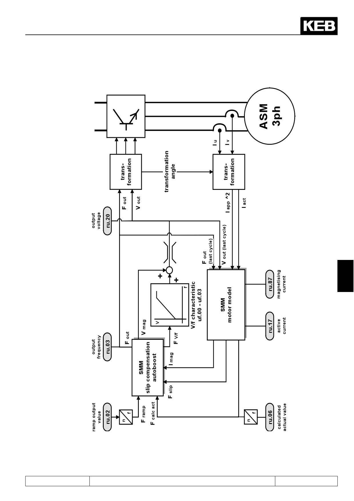
Figure 7.5.3.c SMM
7
Page7.5 - 31
Motor Data and Controller Adjustments of the Asynchronous Motor
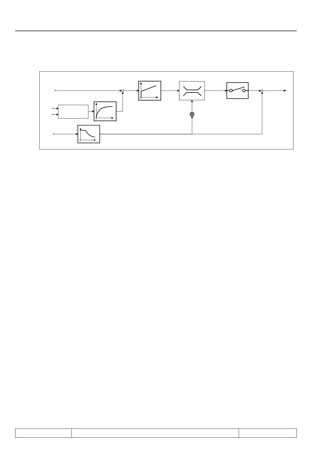
Figure 7.5.3.d Field weakening
ds8 KP Max. voltage
ds9 Ki Max. voltage
ds04.Max. voltage controller
ds10 Maximum voltage (max. -2% of max. output voltage)
0
imr_ref
+
-
1ms
Usd
=SQR(Usd^2+Usq^2)
Usq
-0,75
Imrsoll
omega_1
n
dr.18,dr.20, Imrnenn
Page7.5 - 32
Motor Data and Controller Adjustments of the Synchronous Motor
7.1
Operating and appliance data
1.
Introduction
7.2
Analog in- and outputs I
2.
Summary
7.3
Digital in- and outputs
3.
Hardware
7.4
Setpoint-, rotation- and ramp adjustment
Motor data and controller adjustments of the asynchronous
7.5
4.
Operation
motor
Motor data and controller adjustments of the synchronous
7.6
motor
Selection of Operating
5.
Mode
7.7
Speed control
6.
Initial Start-up
7.8
Torque display and -limiting
7.9
Torque control
7.
Functions
7
7.10
Current control, -limiting and switching frequencies
8.
Error Assistance
7.11
Speed measurement
9.
Project Design
7.12
Positioning and synchronous control
7.13
Protective functions
10. Networks
7.14
Parameter sets
11. Parameter Overview
7.15
Special functions
12. Annex
7.16
CP-Parameter definition
Page7.6 - 1
Motor Data and Controller Adjustments of the Synchronous Motor
7.6.1
Initial settings
7.6 - 3
7.6.1.1
Motor name plate
7.6 - 3
7.6.1.2
Controller configuration
7.6 - 4
7.6.1.3
Actual value source
7.6 - 4
7.6.1.4
Load motor dependent parameter
7.6 - 5
7.6.2
Speed-controlled operation with encoder feedback
7.6 - 6
7.6.2.1
Controller Structure
7.6 - 6
7.6.2.2
Absolute position (encoder 1)
7.6 - 6
7.6.2.3
Absolute encoder
7.6 - 7
7.6.3
Speed-controlled operation without encoder feedback (SCL)
7.6 - 8
7.6.3.1
General
7.6 - 8
7.6.3.2
Initial settings for sensorless operation
7.6 - 8
7.6.3.3
Identification of the motor data
7.6 - 8
7.6.3.3.1
Auto-identification
7.6 - 10
7.6.3.3.2
Single identification
7.6 - 10
7.6.3.3.3
Dead time compensation (uf.18)
7.6 - 12
7.6.3.4
Standstill and starting phase
7.6 - 12
7.6.3.5
Low speed
7.6 - 15
7.6.3.6
Motor model
7.6 - 16
7.6.3.7
Operation with sine-wave filter
7.6 - 18
7.6.4
Block diagram
7.6 - 19
Page7.6 - 2
Motor Data and Controller Adjustments of the Synchronous Motor
7.6
Adjustments of the synchronous motor
There are two different operating modes for the synchronous motor:
-
Speed-controlled operation with encoder feedback
Default speed-controlled operation with encoder feedback, standard version F5A-S
-
Speed-controlled operation without encoder feedback
Speed-controlled operation of synchronous motors without encoder feedback SCL (sensorless closed loop)
is only possible if the electrical characteristic data of the motor are known. The rotor position is emulated by
means of a mathematical model of the synchronous motor. Speed control is based on a speed calculated from
the rotor position rather than on the encoder feedback.
Standard version F5A-S does not contain operating mode SCL. It needs the special software F5E-S.
7.6.1
Initial settings
The following adjustments are always necessary in speed-controlled operation, independently with or without
encoders:
7.6.1.1Motor name plate
Input of the motor rating plate data is at the beginning of each start-up:
- dr.23
DSM rated current
- dr.24
DSM rated speed
7
- dr.25
DSM rated frequency
- dr.27
DSM rated torque
- dr.28
DSM current for zero speed
The following equivalent circuit data can be taken from the data sheet.
Identification of the data offers a high accuracy and acquires the additional line resistance. The identification
can be executed as described in chapter 7.6.3.3 (SCL).
- dr.26
DSM EMK [Vpk * 1000 rpm]
- dr.30
DSM winding resistance
- dr.31
DSM winding inductance
DSM EMK [Vpk * 1000 rpm] / DSM EMK HR [Vpk * 1000 rpm] (dr.26, dr.63)
EMK is the induced voltage in no-load operation and must be entered as peak value (phase-phase) correspon-
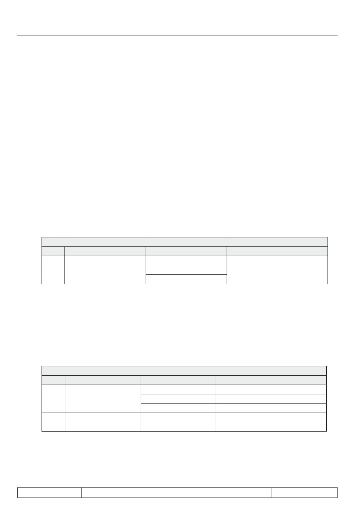
ding to 1000 rpm.
dr.26 = EMKeff x √ 2
Page7.6 - 3
Motor Data and Controller Adjustments of the Synchronous Motor
The maximum permissible speed is also calculated from the EMK which is displayed in ru.79 (abs. speed
[EMK]) corresponding to the DC link voltage: The maximum DC link voltage, UZKmax, can be found in the
power circuit manual.
Max. UDClink x 1000
rpm
ru.79 =
—————————
dr.26
Parameter dr.63 (DSM EMK HR) can be used for higher accuracy.
This parameter is also used after identification of the EMK. To insure downward compatibility with older para-
meter lists, this parameter can be deactivated with "0: Off".
Parameter dr.26 is further valid for the absolute value encoder !
DSM current for zero speed (dr.28)
The stand still current affects the electronic motor protective function (see chapter 7.13.).
7.6.1.2Controller configuration
For controlled operation, the parameter cS.00 must be set to the value 4: "speed control".
cS.00 Speed control configuration
Bit
Description
Value
Function
4: Speed control
0...3
Control mode
5: Torque control
(description see chapter 7.9)
6: Torque/ speed
7.6.1.3Actual value source
The actual value source for speed control must be selected in parameter cS.01 .
Possible values for regulated drives are 0 (speed measurement via encoder interface channel 1) or 1 (speed
measurement via encoder interface channel 2).
Description of the correct parameter setting of the encoder interfaces is made in chapter 7.11 "speed measure-
ment".
S.01 = 2 (calculated actual value) must be selected at operation without speed encoder (only SCL).
cS.01 Actual source
Bit
Description
Value
Function
0: Channel 1
Control to encoder interface 1
0...1
Actual value source
1: Channel 2
Control to encoder interface 2
2: calculated actual value
Control to estimated speed
0: off
2
System inversion
4: an
With activation of the system inversion it is reached that the motor with selected rotation direction "clockwise"
(e.g. by setpoint- or rotation setting) has the physically direction "counter clockwise" respectively at setting
"counter clockwise" the physical rotation "clockwise". Precondition is a correct wiring of motor and speed feed-
back (if available).
Page7.6 - 4
Motor Data and Controller Adjustments of the Synchronous Motor
7.6.1.4Load motor dependent parameter
Fr.10 = 2 (for some applications Fr.10 = 1 /explanation see below) must be entered once after input of the motor
data.
The parameter can only be written in "nop" status !
Fr.10 load motor dependent parameter
Value
Function
0: finished
1:uf.09
Calculation depending on uF.09 respectively voltage class
2: actual DC link
Calculation depending on act. DC link voltage
voltage
The calculation at Fr.10 = 1 is depending on the voltage entered in parameter uF.09 "voltage stabilisation". If
this parameter displays "off" (standard adjustment), then the voltage class of the frequency inverter (400V or
230V) is used.
The current DC link voltage of the frequency inverter, which is proportional to the supply input voltage, is con-
sidered for the calculations at Fr.10 = 2.
However this only applies if uF.09 is on "off".
Thus the following parameter are pre-charged dependent on the motor and inverter data:
Current controller
- dS.00
Kp current
- dS.01
Ki current
7
Torque limits:
- cS.19
Absolute torque reference
- cS.20...23
Torque limits forward / reverse , motoring- generating
- Pn.61
Quick stop torque limit
- dr.33
DSM max. torque
Motor type (only at SCL):
- nn.01
Stabilisation current
- nn.02
Min. speed for current
- nn.03
Max. speed for current
- nn.10
Standstill current
- nn.11
Stabilisation time
Page7.6 - 5
Motor Data and Controller Adjustments of the Synchronous Motor
7.6.2
Speed-controlled operation with encoder feedback
7.6.2.1Controller Structure
Diagram of the controller structure for operation with encoder feedback, see chapter 7.6.4.
7.6.2.2Absolute position (encoder 1)
The system position acquires the mechanical misalignment between rotor and zero position of the mounted
encoder system. This system position is preset at standard KEB motors in factory setting.
In order to operate a customer motor with encoder system it is necessary to make the automatically calibration
to detect the system position.
The following steps must be done:
-
open control release ST (terminal X2A.16)
-
Initial settings described in chapter 7.6.1 must be done.
-
Enter increments per revolution in Ec.01/ Ec.11
-
Check direction of rotation. The speed display ru.09/ ru.10 must be positive in case of manual clockwise
rotation. Otherwise the direction of rotation can to be changed as defined in chapter 7.11.7.
-
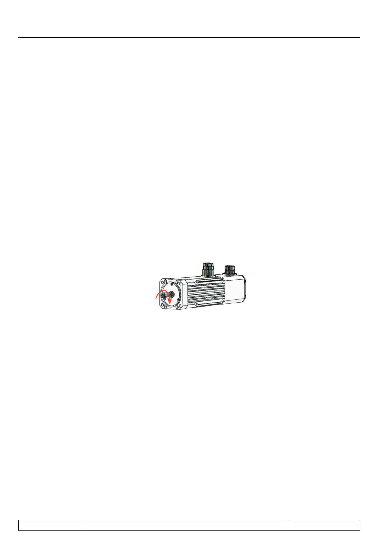
Attention has to be paid to in-phase connection (connect inverter clamps U, V, W on the motor terminal
board with the appropriate contacts) If the cabling is correct, the setting "clockwise rotation" will lead to
the following sense of rotation:
-
Motor must mandatory run with no load.
-
Enter "2206" in In Ec.02/ Ec.12 and confirm message (depending on encoder interface).
-
Close control release
-
The motor is excited with motor current dr.23. Subsequently a forward-/reverse running identification is
executed. On successful conclusion the inverter state displays ru.00 = 127 (drive data calculated).
-
If the motor is unable to rotate freely, or if the direction of rotation does not correspond to the phase po-
sition, the error E.ENC (ru.00 = 32: ERROR! Encoder 1) is triggered.
-
Open control release after successful trimming (ru.00 = 127 drive data calculated).
The current system position is written into the respective parameter (Ec.02/ Ec.12).
Page7.6 - 6
Motor Data and Controller Adjustments of the Synchronous Motor
Compatibility with S4-systems
In order to replace S4-systems by F5-S the following calculation must be carried out:
Ec.07 x ppz
fN x 60
Ec.02 =
——————
ppz =
————
65536
nN
Ec.02 = System position F5-S
Ec.07 = System position S4
ppz = pole-pair number
- The decimal places are multiplied again with 65536.
Example.:
Ec.07 = 49000
ppz = 3
49000 x 3
System position F5=
—————
= 2.24304
65536
Use only decimal places:
Ec.02 =
0.24304 x 65536
= 15928
Additionally, one has to be aware that the resolver cables for the S4-systems are incompatible with the corre-
sponding F5-cables.
7
7.6.2.3Absolute encoder
See chapter 7.11.12.5 "Evaluation intelligent interface"
Page7.6 - 7
Motor Data and Controller Adjustments of the Synchronous Motor
7.6.3
Speed-controlled operation without encoder feedback (SCL)
7.6.3.1General
With this software the speed of the motor can be calculated by the measured currents and the motor data (by
means of a model). This calculated speed can be used as feedback for the speed controller. The necessary mo-
tor data for the model can be identified by the KEB COMBIVERT itself. Static operation with small frequencies
must be avoided, because the model can become unstable. The usable frequency range is approx. 1:100. At
setpoint speed 0, the speed control is deactivated and the motor is aligned using a predefined DC current.
The software version 2.x is only ready to run on the new control hardware xA.F5.230-0018 or -0019.
No compatibility exists between the previous versions 1.x and the versions 2.x; Parameter
lists of the old versions must be adjusted accordingly!
7.6.3.2Initial settings for sensorless operation
The following adjustments are default values and must not be adjusted:
-
The controller configuration cS.00 must be set to value "4: speed control".
-
The actual value source cS.01 must be set to value "2: calculated actual value".
-
The break handling Pn.34 must be activated (default value = 2: without display)
-
The motor model nn.00 must set to value "191".
7.6.3.3Identification of the motor data
The required equivalent circuit data for the motor model can be determined by the KEB COMBIVERT itself.
First, the motor data must be entered according to chapter 7.6.1, and the motor adaption must be executed.
There are two possibilities to start the identification:
-
Writing of parameter dr.48 in inverter state "stop (mod. off)", measurement is starting auto-
matically.
-
Writing of parameter dr.48 in inverter state "nop" with subsequent control release.
Parameter dr.48 cannot be written in other operating conditions.
The measured values can be invalid in case of strong overdimensioning of the inverter. The rated current of the
motor should be at least 1/3 of the maximum short time current limit. The short time current limit is determined
by the overload characteristics and can be taken from the power circuit manual or parameter In.18 (hardware
current).
The direction of rotation during identification of the EMK is always "clockwise rotation"!
Value 82 "calculate drive data / Cdd" is output during measurement in inverter state ru.00. After successful
measurement ru.00 = 127 "drive data calculated/Cddr" is displayed.
If the measurement is interrupted with an error, in ru.00 = 60 "error! drive data/ E.Cdd" is displayed. No correct
operation can be ensured in case of an abort.
The current state of the identification is displayed in parameter dr.62 "state motor ident." The control release
must be switched off in order to leave the identification mode.
Page7.6 - 8
Motor Data and Controller Adjustments of the Synchronous Motor
Parameter dr.48 must be written again in order to start a new measurement.
For safety reasons the output signal "brake release" is not set during measurement, since the motor cannot
generate a defined torque in this time.
Since the identification in the automatic mode is very reliable and for the user the most pleasant method it is
recommended to use generally this method according to chapter 7.6.3.3.1.
dr.48 Motor identification
Bit
Description
Value
Function
0: off
1: Calculation EMK *
Calculation of the EMK from motor data
2: Inductance *
Measurement of the winding inductance respec-
tively
3: Resistance *
Winding resistance
5: Model-/controller parameterisa-
Calculation of the current controller from equiva-
tion *
lent circuit data
!Attention: requires motor rotation!
6: EMK with rotation *
EMK measurement
7: Automatically sequence without
Start of the automatic measurement without
rotation
EMK
8: Automatically sequence with
Start of the automatic measurement with EMK
rotation
0...4
Measurement
9: Dead time detection 2 kHz *
10: Dead time detection 4 kHz *
Measurement of dead time compensation cha-
11: Dead time detection 8 kHz *
7
racteristics for different switching frequencies
12: reserved
13: Dead time detection 16 kHz *
14: Torque detection 2 kHz
15: Torque detection 4 kHz
Detection of the no-load torque at different swit-
16: Torque detection 8 kHz
ching frequencies. During operation this torque is
subtracted from torque display ru.12.
17: reserved
18: Torque detection 16 kHz
19: Current offset detection
Detection of the current offset in phase U and V
20: reserved
0:
1000Hz
32: 500Hz
64: 250Hz
The measuring frequency is changed indepen-
Output fre-
96: 125Hz
dently during measurement.
5...7
quency
128: 62,5Hz
Keep the value at 0: 1000Hz!
160: 32,25Hz
192: 15,625Hz
224: 7,8125Hz
* at dr.48 = 8 auto-identification
Page7.6 - 9