KEB COMBIVERT F5-A,-E,-H 4.0. APPLICATION MANUAL (2008) - page 8
Setpoint-, Rotation- and Ramp Adjustment
oP.63 Reference value high-resolution
The factor for the setpoint calculation is set here:
oP.63 x oP.64
Setpoint =
———————
230
That means: If for oP.63 a value of 230 is set, the setpoint is equal to oP.64 "relative value high-resolution"
The maximum for the setpoint is twice the reference value.
The achievable high resolution is calculated as follows:
oP.64
High resolution =
——————
230
If oP.64 is set to 2000 rpm, i.e., half the maximum value (4000-rpm-mode), the resulting resolution is:
2000 rpm
High resolution =
——————
= 1,86 x 10⁻⁶ rpm
230
This should suffice for all applications.
The adjustment value for oP.63 is calculated as follows:
desired setpoint
oP.63 =
———————————
x 230
oP.64
Example 1
Relative value (oP.64):
2000 rpm
Desired setpoint:
0,140624 rpm
0,140624 rpm
oP.63 =
——————
x 230 = 75497
2000 rpm
Page7.4 - 6
Setpoint-, Rotation- and Ramp Adjustment
Example 2
Relative value (oP.64):
2000 rpm
Desired setpoint:
32,37843 rpm
32,37843 rpm
oP.63 =
———————
x 230 = 17383037
2000 rpm
Resolution and scaling factor are the same as for oP.63. Due to internal rounding, the value of ru.82 may be 1
less than the set value oP.63.
7.4.3
Rotation source oP.01
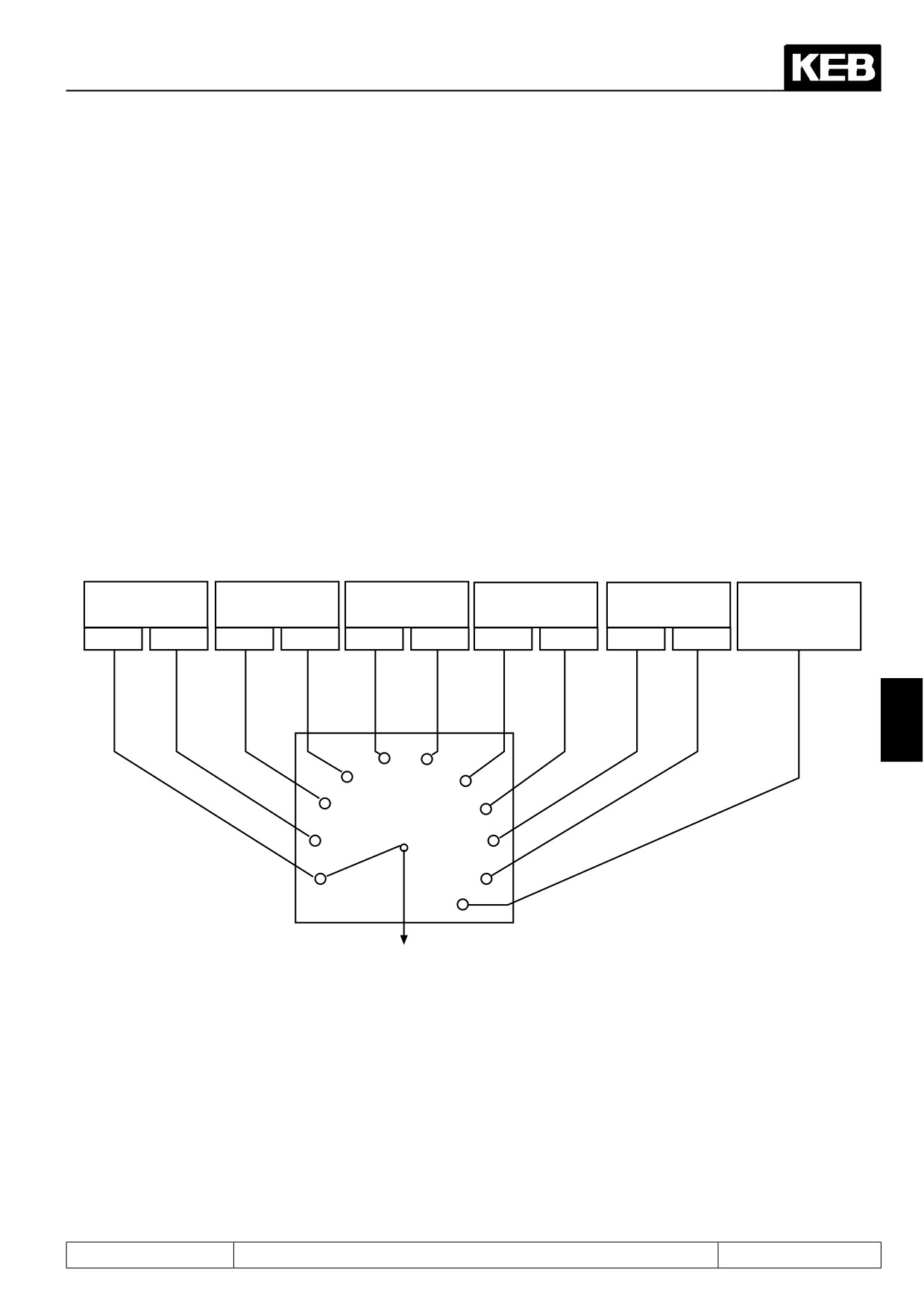
The selection of rotation direction determines the manner in which the rotation direction is adjusted. One can
choose between following possibilities:
Figure 7.4.3 Rotation selection with oP.01
digital
Terminal strip
Terminal strip
Setpoint
Control word
Setpoint depen-
oP.02
forward/reverse
Run / Stop
dependent
SY.50
dent
Control word
0-lim.
abs.
0-lim.
abs.
0-lim.
abs.
LS
no LS
0-lim.
abs.
Run / Stop
7
4
5
3
6
2
7
1
8
0
9
oP. 1
10
0-limited or absolute
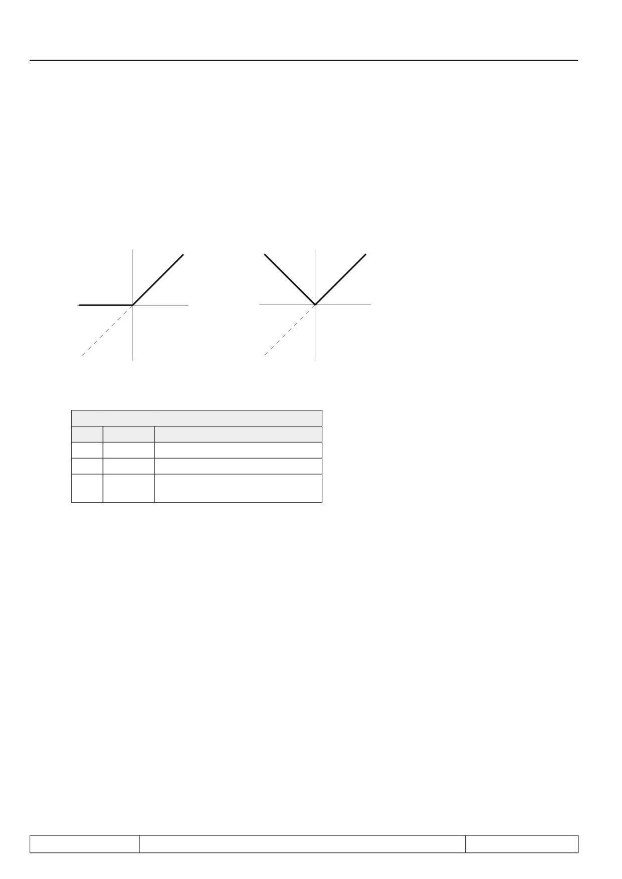
Concerning the adjustment of direction of rotation it is differentiated between two evaluations:
0 limited:
negative setpoints are set to zero, i.e. only positive setpoints are driven in accordance with the selected rotation
direction
Page7.4 - 7
Setpoint-, Rotation- and Ramp Adjustment
absolute:
no sign of the set value is evaluated and it is always driven with the amount in accordance with the selected
rotation direction
Figure 7.4.3.a Absolute and 0 limited set value setting
0-limited
absolute
Setpoint
Setpoint
Setpoint
Setpoint
adjust-
adjust-
ment
ment
Rotation setting oP.02 ; (oP.01 = 0 or 1)
oP.02: Rotation setting
Bit
Display
Setpoint rotation
0
LS
Standstill (Low Speed)
1
F
forward (clockwise rotation)
2
R
reverse (counter-clockwise rota-
tion)
Rotation adjustment via terminal strip
The rotation selection via terminal strip allows the adjustment of the direction of rotation via switch or from a
primary control.
Direction forward input selection (Run / Stop) oP.60, direction reverse (forward / reverse) oP.61
With parameter oP.60 one input is determined for rotation direction forward (or run/stop) and with oP.61 one
input for rotation direction reverse (respectively forward/reverse). (see chapter 7.3)
Page7.4 - 8
Setpoint-, Rotation- and Ramp Adjustment
oP.01 = "2" or "3"
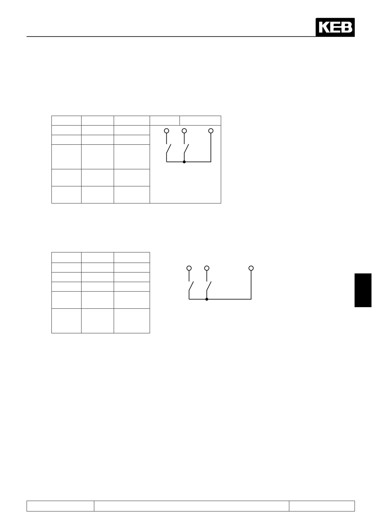
In case of rotation selection forward/reverse (oP.01= "2" or "3") the inputs determined with oP.60 and oP.61
work as follows:
Forward
Reverse
Input
X2A.14
X2A.15
F
R
Function
0
0
LS
0
1
counter-
clockwise
rotation
1
0
clockwise
rotation
1
1
clockwise
rotation
oP.1 = "4" or "5"
In the case of rotation selection run/stop and forward/reverse (oP.01= "4" or "5") the inputs determined with
oP.60 and oP.61 work as follows:
forward
reverse
Input
X2A.14
X2A.15
F
R
Function
0
0
LS
0
1
LS
7
1
0
clockwise
rotation
1
1
counter-
clockwise
rotation
Rotation direction is dependent on the sign of the setpoint
The direction of rotation can be defined with the preadjusted set value signal. In the case of analog signals
through adjustment of positive or negative voltages. In the case of digital signals through adjustment of positive
values (without sign) or negative values (negative sign in the display).
Following adjustments are possible:
Evaluation with LS (Switch off the modulation) (oP.01 = 6 or 10)
In this case "F" or "R" must be set via a digital input, digital via oP.2 or "start" via control word SY.50 in order for
the inverter to modulate. It is unimportant which rotation setting is used, as the direction of rotation is dependent
on the setpoint.
Page7.4 - 9
Setpoint-, Rotation- and Ramp Adjustment
oP.01 = 10: The rotation direction release is done exclusively via the control word Run/Stop.
No rotation direction set
-> LS (Modulation disabled)
A direction of rotation is set and oP.01 = 6 or 10
-> Clockwise direction of rotation
negative value
-> Anti-clockwise direction of rotation
Evaluation without LS (oP.01 = 7)
In this case the inverter always modulates.No direction of rotation needs to be adjusted.
oP.01 = 7:
pos. value (also 0)
-> Clockwise direction of rota-
tion
negative value
-> Anti-clockwise direction of
rotation
Rotation direction dependent on the control word SY.50
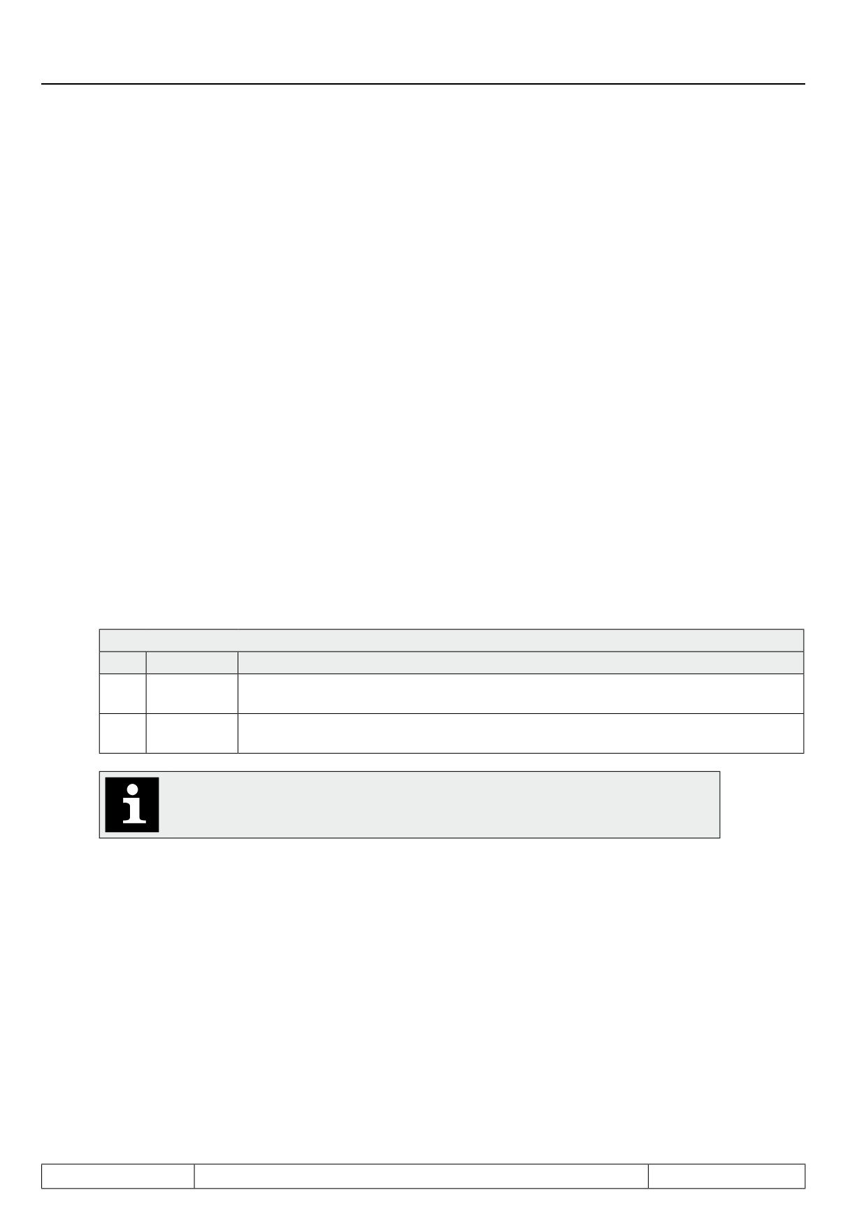
The control word is used for the state control of the inverter via bus. In order for the inverter to react to the con-
trol word, the respective control process must be enabled (oP.01=8 or 9; fr.02 = 5). When adjusting the direction
of rotation via the control word, the setpoint can be evaluated 0-limited (oP.01 = 8) or absolute (oP.01 = 9).
Control word Sy.50
Bit
Function
Description
0 = Setpoint rotation Stop; 1 = Rotation direction Run
2
Run / Stop
(source of set value direction op.1 = 6, 8, 9 or 10)
0 = Setpoint rotation forward; 1 = Rotation direction counter-clockwise
3
For / Rev
(source of set value direction op.1 = 6, 8, 9 or 10)
If Run/Stop is to be adjusted over the control word, oP.02 must be set to "0". The
terminals F/R may not be wired (OR-operation of terminal, oP.02 and Sy.50).
Page7.4 - 10
Setpoint-, Rotation- and Ramp Adjustment
7.4.4
Fixed frequencies (oP.18...23)
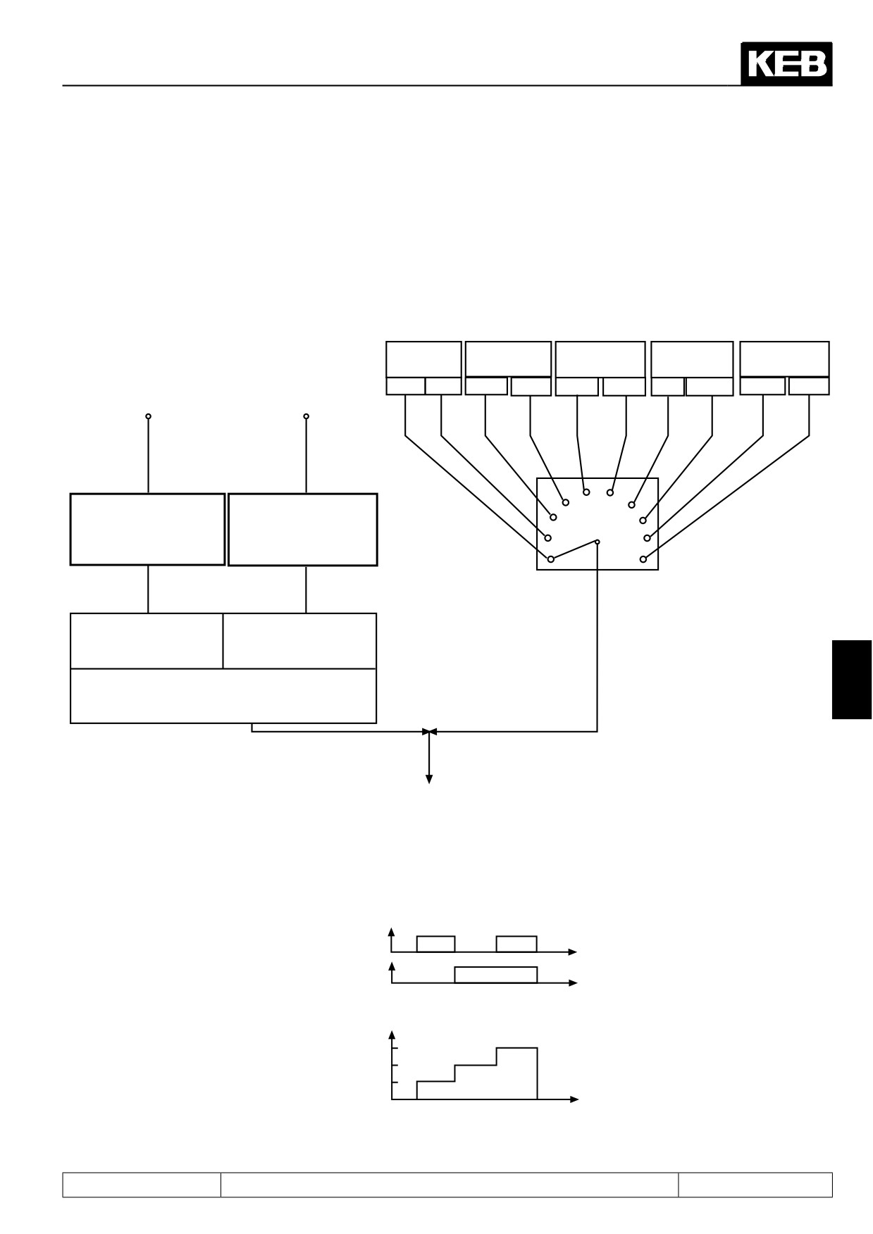
The KEB COMBIVERT supports up to 3 fixed frequencies for each parameter set, which can be selected via
two digital inputs. With oP.19 and oP.20 the inputs required for the selection are defined (also see "Digital in-
puts" Chapt. 7.3.11). The rotation direction source for fixed value mode is defined with oP.18. The adjustment
is independent of oP.01 and is valid exclusively for the fixed frequencies. The adjustment of a fixed frequency
has priority over the "normal" setpoint adjustment.
Figure 7.4.4 Fixed values
digital
Terminal strip
Terminal strip
Setpoint
DRIVECOM
oP.2
For / Rev
Run / Stop
dependent
SY.50
Input
Input
0-lim. abs.
0-lim. abs.
0-lim. abs.
LS
no LS
0-lim.
abs.
fixed frequency 1
fixed frequency 2
4
5
3
6
oP.19 Step value input
oP.20 Step value input
2
7
selection 1
selection 2
1
8
0...4095
0...4095
(according to table)
(according to table)
0
9
oP. 18
Fixed value
Rotation direction source
Fixed frequency 1
Fixed frequency 2
oP.21:
oP.22:
-4000...4000 rpm
-4000...4000 rpm
7
Fixed frequency 3
oP.23: -4000...4000 rpm
Setpoint limits
Selection of fixed values
Figure 7.4.4.a Selection of fixed values
Input fixed value 1
Input fixed value 2
Setpoint
f3
f2
Fixed value f1...f3
f1
t
Page7.4 - 11

Setpoint-, Rotation- and Ramp Adjustment
Step value rotation source (oP.18)
With oP.18 it is defined how the direction of rotation is determined in case of active fixed value.The function and
the value range correspond to oP.1.
oP.18: Step value rotation source
Value
Function
0
Digital via oP.2; setpoint 0-limited
1
Digital via oP.2; setpoint absolute
2
Terminal strip F/R; setpoint 0-limited
3
Terminal strip F/R; setpoint absolute
4
Terminal strip Run/Stop; setpoint 0-limited
5
Terminal strip Run/Stop; setpoint absolute
6
Setpoint-dependent with LS-recognition
7
Setpoint-dependent without LS-recognition
8
Control word SY.50; 0-limited
9
Control word SY.50; 0-absolute
10
Setpoint + control word(SY.50) R/S
Step value input selection 1 and 2 (oP.19; oP.20)
See chapter 7.3.1 "digital inputs".
Step value 1...3 (oP.21, oP.22, oP.23)
The three step values oP.21...23 are set-programmable and can be adjusted in the range of -4000...4000 rpm.
Page7.4 - 12
Setpoint-, Rotation- and Ramp Adjustment
7.4.5
Setpoint limits
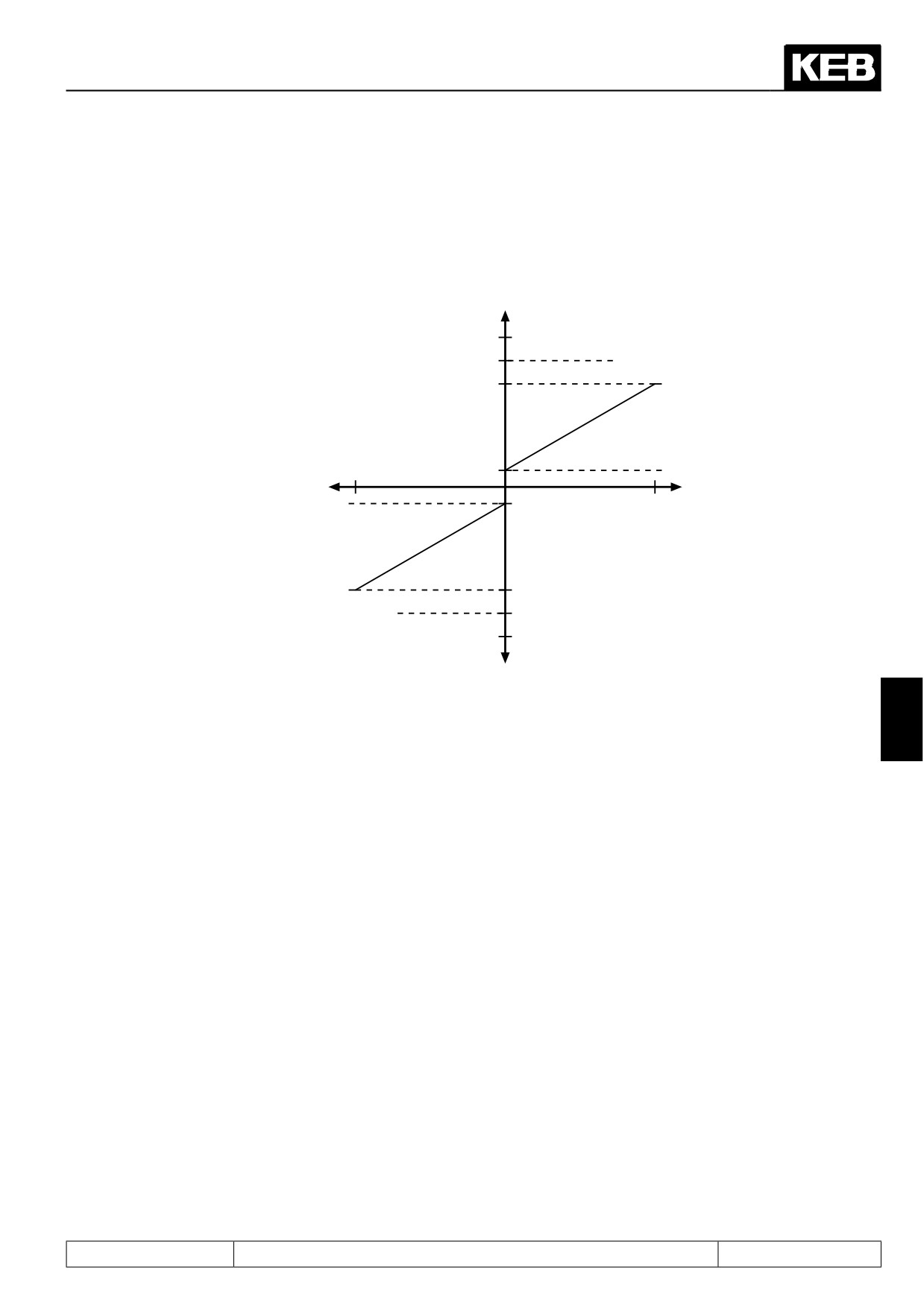
Following limit values can be preadjusted:
Figure 7.4.5 Setpoint limits
+n [rpm]
4000
Absolute maximal setpoint
oP.14
forward
oP.10
Maximal frequency for-
ward
-100
oP.6
Minimal frequency for-
oP.7*1 (oP.6)
+100
ward
Setpoint [%]
Setpoint [%]
Minimal frequency reverse
oP.11*1 (oP.10)
oP.15*1 (oP.14)
Maximal value reverse
-4000
Absolute maximal frequency
reverse
7
-n [rpm]
*1 If the value "=For" is adjusted in these parameters (limit values rotation direction reverse), then the adjusted
values for rotation direction forward (oP.6, oP.10 and oP.14) are valid.
Min./ max. setpoints (oP.6, oP.7, oP.10, oP.11)
In case of analog and percentaged setpoint adjustment in percent the minimal and maximal frequencies form
the characteristic for the frequency calculation (0% = minimal frequency; 100% = maximal frequency). In case
of digital setpoint adjustment or fixed value the minimal and maximal frequencies limit the setpoint. Separate
limits can be adjusted for both rotation directions. If the value "For" is adjusted for rotation direction "Reverse",
then the values for "Forward" are valid.
Setting range:
oP.6: 0...4000 rpm
Default: 0 rpm
oP.10: 0...4000 rpm
Default: 2100 rpm
oP.7: =For, 0...4000 rpm
Default: =For
oP.11: =For, 0...4000 rpm
Default: =For
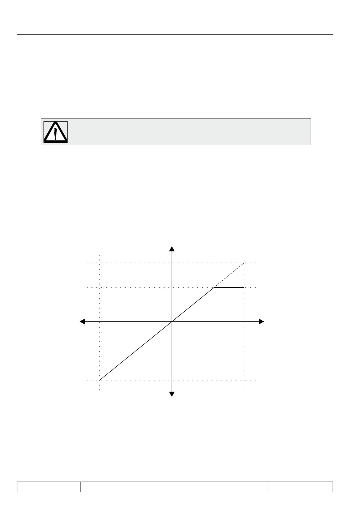
Absolute maximum setpoints (oP.14, oP.15)
After the minimal and maximal frequencies the setpoint is limited through the absolute maximal frequency and
subsequently transferred to the ramp generator. Since the analog setpoint is always calculated onto the maxi-
mal frequencies (oP.10, oP.11), it is possible, to adjust the characteristic of the analog setpoint with the same
gain for both rotation directions (see Fig.7.4.5.a) in spite of different maximal output frequencies. If the value
Page7.4 - 13
Setpoint-, Rotation- and Ramp Adjustment
"For" is adjusted in oP.15, then the absolute maximal speed of oP.14 is valid for both directions of rotation.
Max. output value forward (oP.40) / Max. output value reverse (oP.41)
All other limits (oP.10 / oP.11 "max. reference" and oP.14 / oP.15 "abs. max. reference") limit the speed setpoint
exclusively.
This function is active only if the alarm for the utilised encoder channel is activated (alarm
= on) in parameter Ec.42 "encoder alarm mode". In vector-controlled operation without
speed feedback, speed limiting is always active.
The status "58: ERROR!speed limit exceeded" (E.OS) is triggered if ru.07 "actual value display" exceeds either
oP.40 / oP.41 "output frequency limit" or ru.79 "abs. speed value EMK" (only for synchronous motors).
With oP.40 / oP.41, the user sets limits that may not be exceeded by the application under any circumstances.
ru.79 shows the maximum speed for a synchronous motor which, if exceeded, leads to an EMK of the motor
high enough to damage the DC-intermediate circuit of the inverter.
Reason for the occurence of excessive speed can be too small a distance between the maximum setpoint and
the speed limit, so that overshoots can trigger the error. Other causes can be (e.g., caused by EMK) malfunc-
tions in the speed measurement or a noisy, insufficiently smoothed speed estimate in the encoderless control
(SCL or ASCL).
Fig. 7.4.5.a
Setpoint limits
+n [rpm]
(oP. 10)
Absolute maximal va-
lue forward
(oP.14)
Maximal frequency
forward
Setpoint [%]
Setpoint [%]
-100%
+100%
Maximal frequency
(oP.11)
reverse
-n [rpm]
Page7.4 - 14
Setpoint-, Rotation- and Ramp Adjustment
7.4.6
Setpoint calculation
The unit differentiates between two setpoint adjustments:
- the percentage setpoint adjustment
With the adjusted setpoint limits the speed range 0%...100% is defined. In this case the adjustment of 0%
corresponds to the minimal speed and 100% to the maximal speed.
The speed after the setpoint limiting is calculated according to following formula:
oP.10-oP.06
Positive setpoint = oP.06 + (setpoint setting [%] x
―――――
)
100%
oP.11-oP.07
Negative setpoint = oP.07 + (setpoint setting [%] x
—————
)
100%
The absolute setpoint adjustment, i.e. the setpoint is directly adjusted as speed and limited through the corre-
sponding minimal and maximal values as well as through the absolute maximal values.
The setpoint sources are assigned as follows:
Setpoint adjustment in percent
Absolute setpoint adjust-
ment
Terminal strip (analog setpoint)
Keyboard/Bus absolute
Keyboard/bus in %
Set speed value Sy.52
Motor potentiometer
Speed Measurement
7
Technology Control
High resolution
Fade out target for setpoint
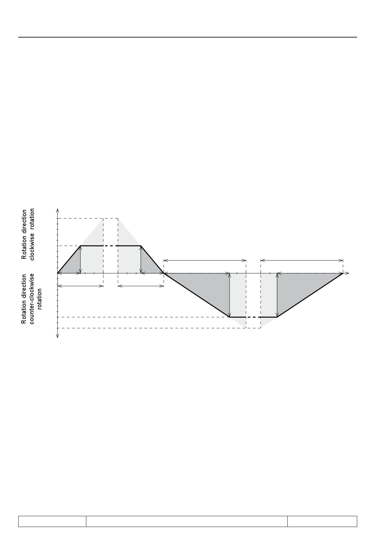
Setting ranges are faded out with this function, in order to avoid resonances. The target is pass through with
the ramp. The setpoint value is always adjusted to the upper or lower limit of the target.
Parameter:
oP.65
Min. proh. reference 1
oP.66
Max. proh. reference 1
oP.67
Min. proh. reference 2
oP.68
Max. proh. reference 2
The parameters are not programmable.
The adjusted values are accepted still as setpoint value, so that the function is not active in case that lower
and upper limit have the same value. If a higher value is selected for the lower limit than for the upper limit, the
function is also not active.
Page7.4 - 15
Setpoint-, Rotation- and Ramp Adjustment
7.4.7
Ramp generator
The ramp generator assigns an adjustable time to a speed change, during this time the change stall take
place. The acceleration time (for pos. speed changes) and deceleration time (for neg. speed changes) can be
adjusted separately for both directions of rotation. To enable jerk-free acceleration and deceleration, so-called
S-curves can be adjusted in addition to it.
The ramp times refer to 1000 rpm (at ud.02 = 4), or to 2000 rpm (at ud.02 = 8) and change in proportion to the
mode. The times to be adjusted are calculated as follows:
desired ramp time
Speed change (∆n)
-----------------------------------
=
----------------——----
ramp time to be adjusted (oP.28...oP.31)
1000 rpm (dep.on ud.02)
Fig. 7.4.7
Acceleration and deceleration times
+n [rpm]
1000
500
oP.29 *1
oP.31 *1
∆ n
∆n
∆ t
∆ t
∆ t
∆ t
0
oP.28
oP.30
∆ n
∆ n
800
1000
-n [rpm]
oP.28
Acceleration time forward
If the value "=For" is adjusted in these parameters (accelerati-
on and deceleration times for rotation direction reverse), then
oP.29
*1
Acceleration time reverse
*1
the values of rotation direction forward (oP.28 and oP.30) are
oP.30
*2
Deceleration time forward
valid.
oP.31
*1
Deceleration time reverse
∆ n
speed change
*2
If the value "=Acc" is adjusted, then the value of acceleration
forward (oP.28) is valid.
∆ t
Acceleration time for ∆n
Page7.4 - 16
Setpoint-, Rotation- and Ramp Adjustment
Acceleration/deceleration time factor (oP.62)
The time factor extends the standard ramp time (oP.28...31) by the adjusted value. The S-curve time do not
change.
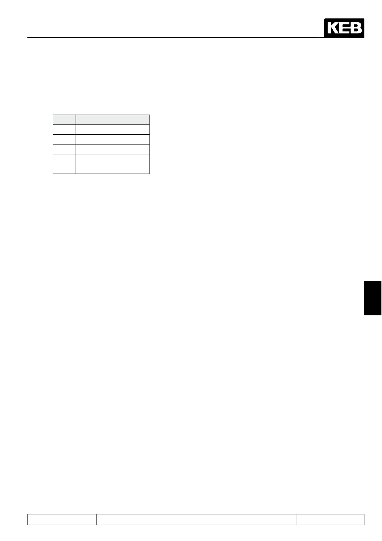
Value
Ramp time
0
Adjusted value x 1
1
Adjusted value x 2
2
Adjusted value x 4
3
Adjusted value x 8
4
Adjusted value x 16
Calculation of the acceleration and deceleration times
1000 rpm x real ramp time
oP.28...oP.31 =
——————————————
∆n
Example
A drive should accelerate from 100 rpm to 1000 rpm in 5 s.
5s x 1000 rpm
oP.28 =
———————--------
= 5,5 s
1000 rpm - 100 rpm
7
S-curve time
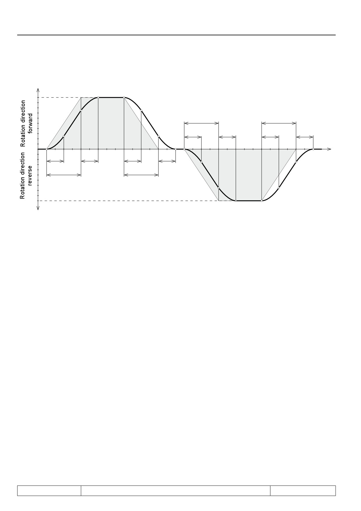
For some applications it is of advantage when the drive starts and stops jerk-free. This is achieved through a
straightening of the acceleration and deceleration ramps. The straightening time, also called S-curve time, can
be preadjusted with the parameters oP.32...oP.35. But S-curves are executed only with the adjustment oP.27
"Ramp with constant rise".
Page7.4 - 17
Setpoint-, Rotation- and Ramp Adjustment
Figure 7.4.7.a S-curve time
+n [rpm]
1000
oP.29
oP.31
oP.33
oP.33
oP.35
oP.35
t [s]
0
oP.32
oP.32
oP.34
oP.34
oP.28
oP.30
-1000
-n [rpm]
oP.28
Acceleration time forward
If the value "For" is adjusted in these parameters (for ro-
*1
tation direction reverse), then the values adjusted in the
oP.29
Acceleration time reverse
*1
parameters for rotation direction forward are valid.
*2
oP.30
Deceleration time forward
oP.31
*1
Deceleration time reverse
If the value "=Acc" is adjusted, then the value for acce-
*2
leration forward (oP.28) is valid.
oP.32
S-curve time acceleration forward
*1
oP.33
S-curve time acceleration reverse
If the value "=Acc" is adjusted, then the value adjusted
3
in parameter oP.32 is valid for all S-curve times. Value
oP.34
S-curve time deceleration forward
*3
"0" switches the corresponding S-curve off.
*1
oP.35
S-curve time deceleration reverse
In order to drive defined ramps with activated S-curve time, the preadjusted acceleration and deceleration times
(oP.28...oP.31) must be larger than the S-curve time (oP.32...oP.34) belonging to it.
Example for acceleration with rotation direction forward
At the beginning and the end of the acceleration ramp a parabolic curve is driven for the time adjusted in para-
meter oP.32. If the S-curves are traversed completely, the set ramp time is increased by oP.32.
Upper S-curve times (op.70...op.73)
Page7.4 - 18

Setpoint-, Rotation- and Ramp Adjustment
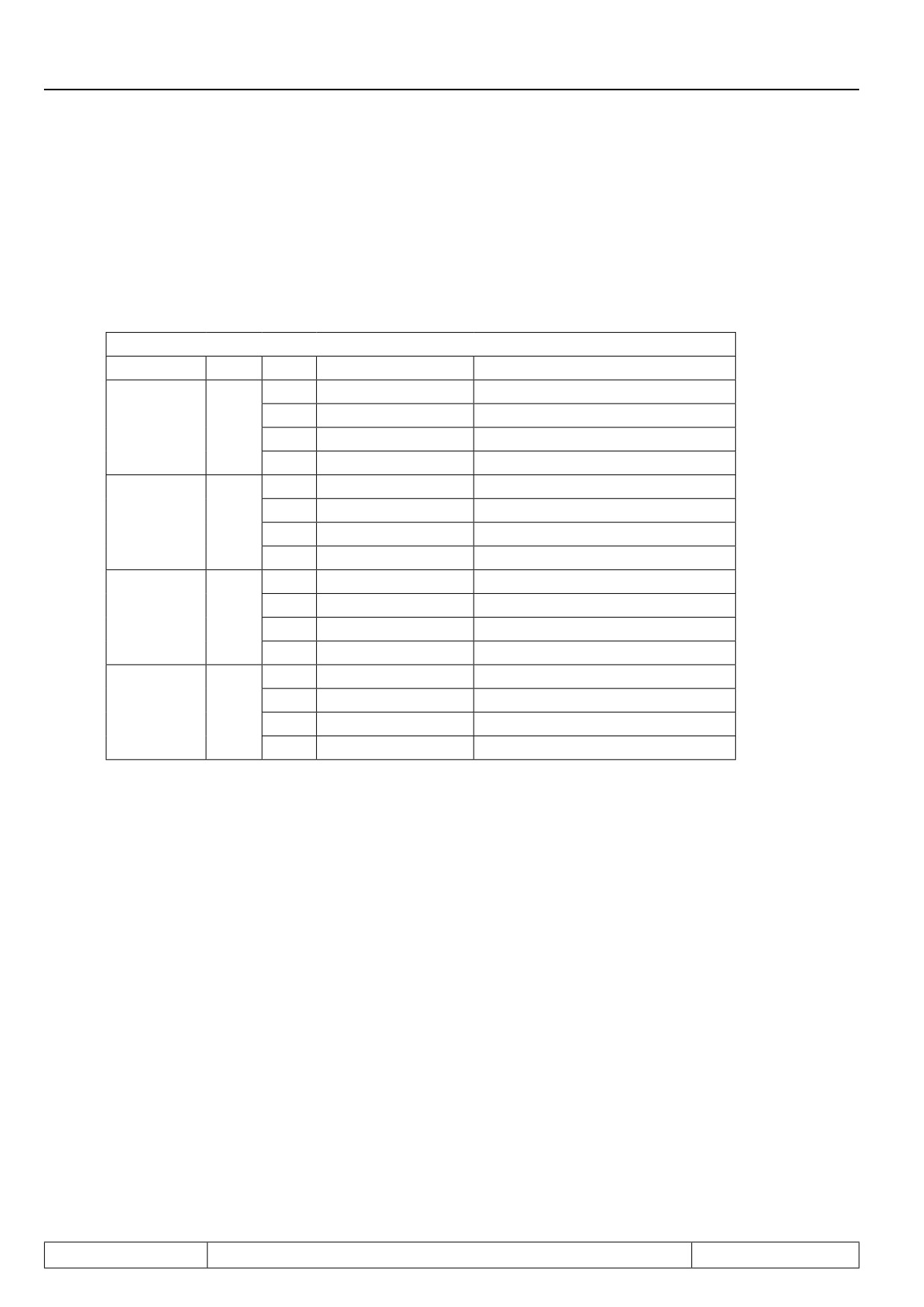
Parameters oP.70...oP.73 adjust the upper S-curves. If the value is -1 (default setting), the parameters oP.32...
oP.35 apply for the upper and lower S-curves (see figure 7.4.7.a).
Parameter
Name
Va-
Meaning
lue
Lower S-curve
Lower S-curve time acc.
also applies to the upper S-curve if oP.70 = -1
oP.32
forward
0
off
also applies to the upper S-curve if oP.71 = -1
Lower S-curve time acc.
oP.33
0
off
reverse
-1
= op.32
also applies to the upper S-curve if oP.72 = -1
Lower S-curve time dec.
oP.34
0
off
forward
-1
= op.32
also applies to the upper S-curve if oP.73 = -1
Lower S-curve time dec.
oP.35
0
off
reverse
-1
= op.34
upper S-curve
Upper S-curve time acc.
0
off
oP.70
forward
-1
= op.32 (default)
0
off
Upper S-curve time acc.
oP.71
-1
= op.33 (default)
reverse
-2
= op.70
0
off
7
Upper S-curve time dec.
oP.72
-1
= op.34 (default)
forward
-2
= op.70
Upper S-curve time dec.
0
off
oP.73
reverse
-1
= op.35 (default)
Page7.4 - 19
Setpoint-, Rotation- and Ramp Adjustment
7.4.8
acc dec mode
7.4.8.1Ramp with constant ascent
The different ramp functions can be adjusted separately for every frequency change (acceleration forward,
deceleration forward and so on). The selection is made with oP.27 and is adjustable separately in each set. The
function is activated after pressing "ENTER".
oP.27: Acc dec mode
Ramp
Bit
Value
Mode
Reference speed
0
const. ascent
1000 rpm (dep.on ud.02)
Acc.
1
const. time
Actual set value
clockwise
0 + 1
2
* const. time
Last set value at constant run
rotation
3
Ogive run
1000 rpm (dep.on ud.02)
0
const. ascent
1000 rpm (dep.on ud.02)
dec.
4
* const. time
Actual set value
clockwise
2 + 3
8
const. time
Last set value at constant run
rotation
12
Ogive run
1000 rpm (dep.on ud.02)
0
const. ascent
1000 rpm (dep.on ud.02)
Acc.
counter-clo-
16
const. time
Actual set value
4 + 5
ckwise rota-
32
* const. time
last set value at constant run
tion
48
Ogive run
1000 rpm (dep.on ud.02)
0
const. ascent
1000 rpm (dep.on ud.02)
dec.
counter-clo-
64
* const. time
Actual set value
6 + 7
ckwise rota-
128
const. time
Last set value at constant run
tion
192
Ogive run
1000 rpm (dep.on ud.02)
* Do not adjust these values - they are only sensible, if acceleration does not take place from standstill or de-
celeration is not made to standstill.
7.4.8.2Ramp with constant time
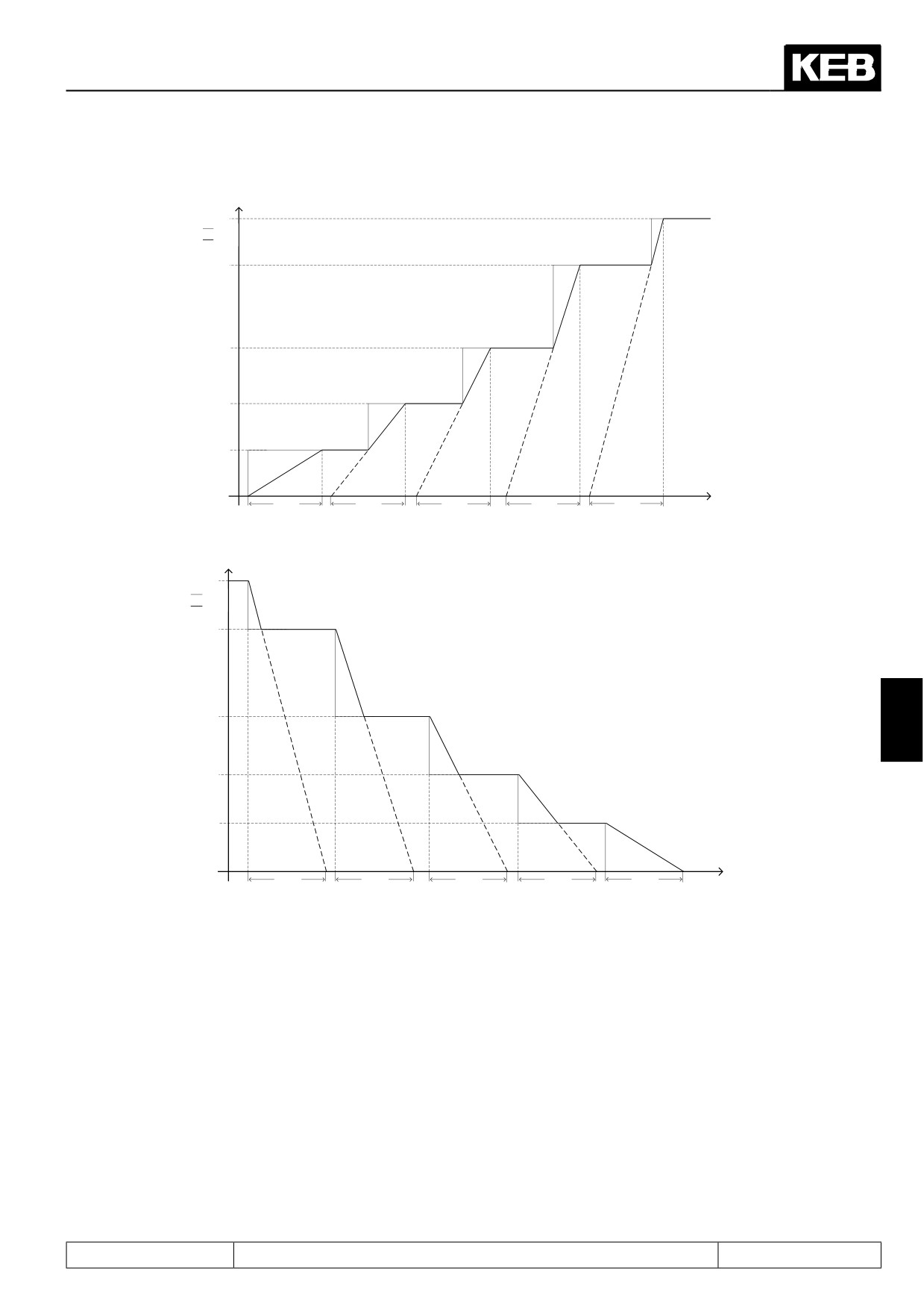
At the ramp with constant time the acceleration and deceleration times adjusted with oP.28...oP31 always equal
the real ramp times, independent of the set value. In this operating mode S-curves are not possible.
Here an example for the use of ramps with constant time:
Two conveyor belts run with different speeds. Both of them receive the Stop-command at the same time. The
belts reduce the speed in proportion to the adjusted time and come to a standstill simultaneously.
Page7.4 - 20
Setpoint-, Rotation- and Ramp Adjustment
Figure 7.4.8.a Forward acceleration with constant ramp time
n_set
n_actual
t_rampe
t_rampe
t_rampe
t_rampe
t_rampe
t
Figure 7.4.8.b Forward deceleration with constant ramp time
n_set
n_actual
7
t_rampe
t_rampe
t_rampe
t_rampe
t_rampe
t
If the mode constant time is activated for a ramp, then the S-curve function is deactivated for this ramp. The
ascent is limited to minimum to 1000 -1 rpm (dep.on ud.02) 4800 s.
Page7.4 - 21
Setpoint-, Rotation- and Ramp Adjustment
Calculations
Fig. 7.4.8.c
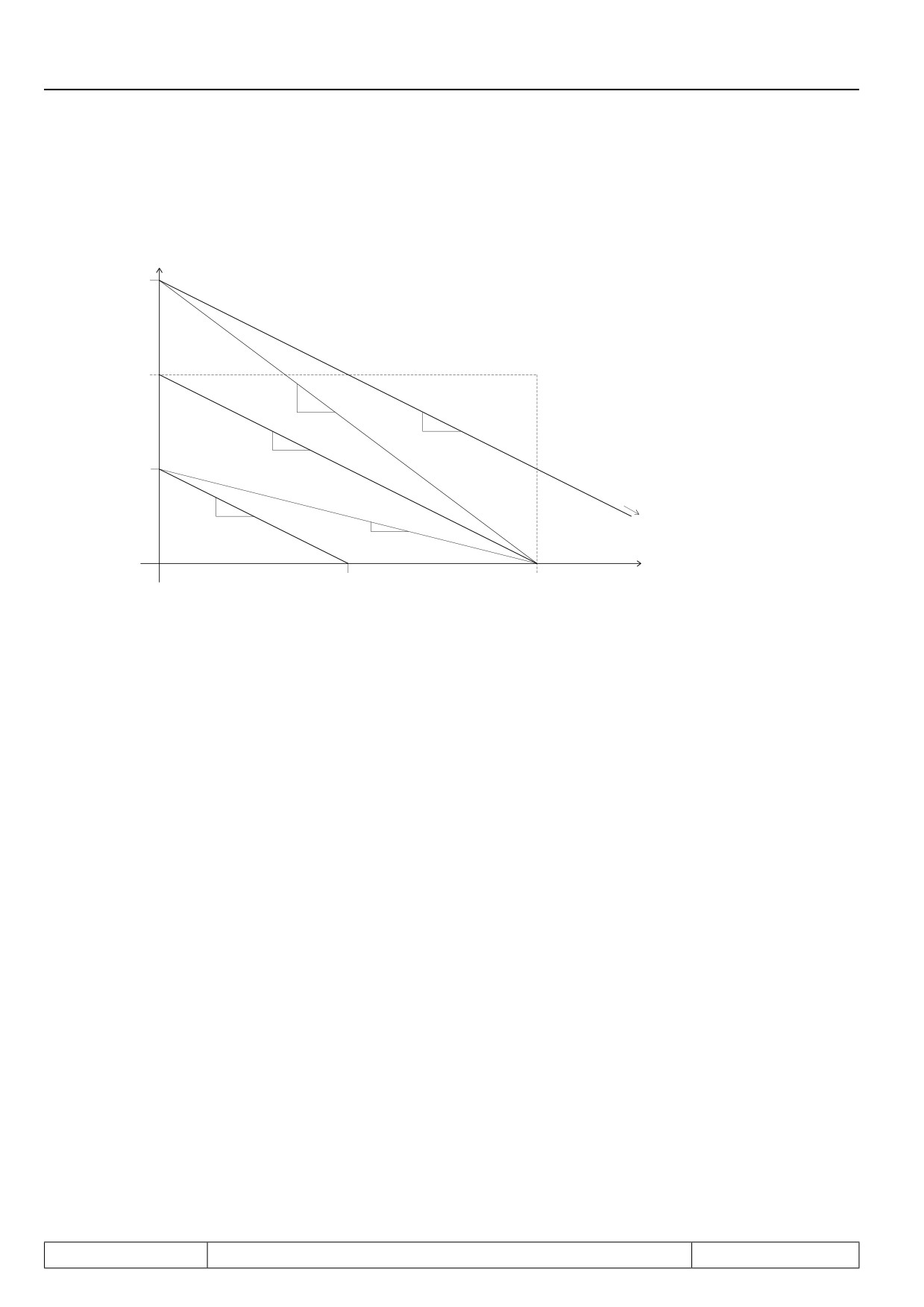
Calculations
n_set
n_2
1000 rpm
delta_n_2
variable
delta_t
delta_n
constant
delta_n
delta_t
constant
delta_t
n_1
delta_n
t_2
constant
delta_t
delta_n_1
variable
delta_t
t
t_1
t_rampe
The speed change per raster scan Δ_t (step size Δ_n) for the mode constant ascent is calculated from the ramp
time t_ramp and the reference speed (1000 rpm dep. on ud.2):
1000 rpm
Δ n =
—————————
t_ramp /Δ t
For different set values the real ramp time is calculated according to following formula:
n_set
t = t_ramp x
—————
1000 rpm
The actual step size for the mode constant time is calculated from the step size delta_n and the actual set
value n_set as follows:
n_set
Δ n(variable) = Δ n x
—————
1000 rpm
For a simplification of the internal calculations 1024 rpm (resp. 2048 rpm or 4096 rpm dependent on ud.2) are
used as reference speed.
n_set
Δ n(variable) = Δ n x
—————
1024 rpm
Page7.4 - 22
Setpoint-, Rotation- and Ramp Adjustment
As a result an error of -2,4 % for the real ramp time occurs. If a certain real ramp time has to be adjusted, the
desired value must be divided by 1.024. Example:
Desired ramp time = 10 s
Adjusted ramp time = 10 s / 1,024 = 9,77 s
7.4.8.3Ogive run
In the mode "constant ascent", a change in setpoint while the inverter is still in the acceleration / deceleration
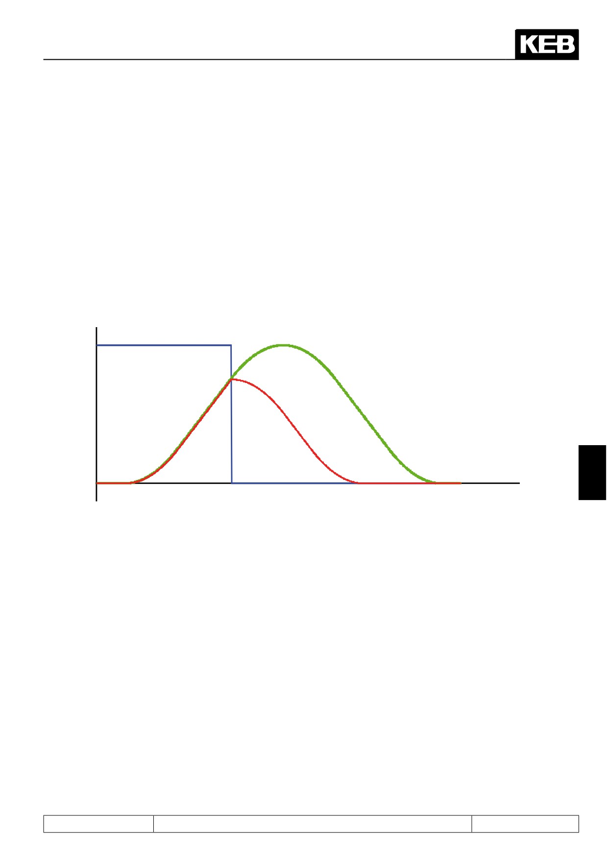
phase will lead to the fastest possible response. If the new setpoint requires, e.g., a switch from acceleration
to deceleration, the acceleration ramp is interrupted and the deceleration ramp is started immediately. This can
lead to an undefined jolt. If ogive run is selected, the programmed S-curve-times are always used, the accele-
ration / deceleration change continuously, and no undefined jolt occurs.
Figure 7.4.8.3 Ogive run
ru.01: Set value display
ru.02: Ramp output display with
ogive run
7
ru.02: Ramp output display
time
without ogive run
Page7.4 - 23
Setpoint-, Rotation- and Ramp Adjustment
Page7.4 - 24
Motor Data and Controller Adjustments of the Asynchronous Motor
7.1
Operating and appliance data
1.
Introduction
7.2
Analog in- and outputs I
2.
Summary
7.3
Digital in- and outputs
3.
Hardware
7.4
Setpoint-, rotation- and ramp adjustment
Motor data and controller adjustments of the asynchronous
7.5
4.
Operation
motor
Motor data and controller adjustments of the synchronous
7.6
motor
Selection of Operating
5.
Mode
7.7
Speed control
6.
Initial Start-up
7.8
Torque display and -limiting
7.9
Torque control
7.
Functions
7
7.10
Current control, -limiting and switching frequencies
8.
Error Assistance
7.11
Speed measurement
9.
Project Design
7.12
Positioning and synchronous control
7.13
Protective functions
10. Networks
7.14
Parameter sets
11. Parameter Overview
7.15
Special functions
12. Annex
7.16
CP-Parameter definition
Page7.5 - 1