KEB COMBIVERT F5-A,-E,-H 4.0. APPLICATION MANUAL (2008) - page 7
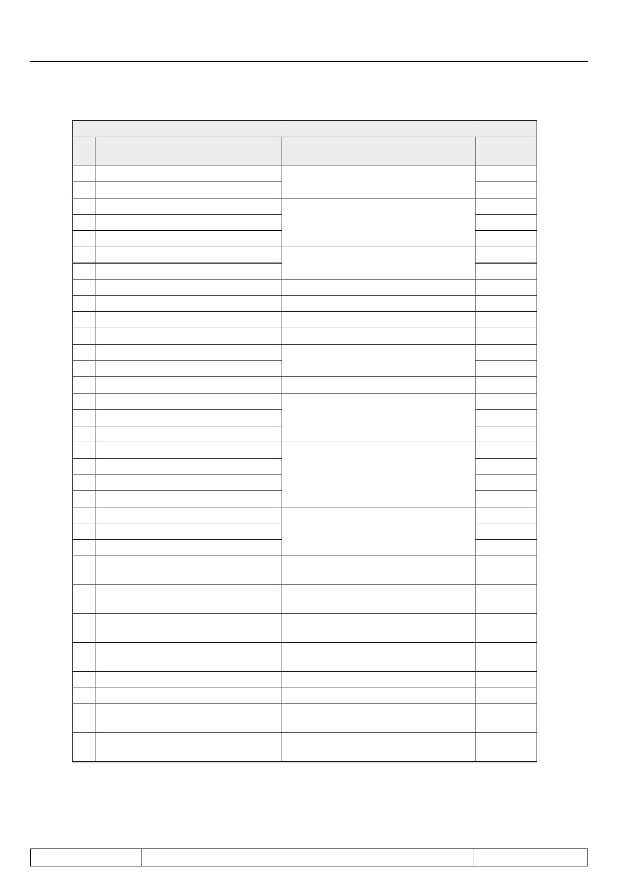
Digital In- and Outputs
di.11...di.22 Input function
Func. para
Bit
Value
Explanation
1)
0
1: Fixed frequency 1
oP.19
Select fixed values
1
2: Fixed value 2
oP.20
2
4: Increase motor potentiometer
oP.56
3
8: Decrease motor potentiometer
Motor potentiometer
oP.57
4
16: Reset motor potentiometer
oP.58
5
32: forward
oP.60
Rotation setting
6
64: reverse
oP.61
7
128: Reset error
Release reset
di. 09
8
256: Ramp stop
Stop ramp
Pn.23
9
512: DC braking
Activate DC braking
Pn.29
10
1024: Energy saving function
Flux reduction
uF.08
11
2048: set
Fr.07
Parameter set selection
12
4096: Reset to set 0
Fr.11
13
8192: external fault
Release error state at inverter
Pn.04
14
16384: Store AN1
An.03
15
32768: Store AN2
Activate save mode for analog inputs
An.13
16
65536: Store AN3
An.23
17
131072: Start timer 1
LE.17
18
262144: Reset timer 1
LE.19
Start / stop timer
19
524288: Start timer 2
LE.22
20
1048576: Reset timer 2
LE.24
21
2097152: Reset PID controller
cn. 11
22
4194304: Reset PID (I part)
PID controller
cn. 12
23
8388608: Reset PID overlay
cn. 13
16777216: Posi/synchronous activa-
24
Activate posi / sync module
PS.02
tion
Adjustment of the master position
25
33554432: Slave adjustment
PS.03
(Addition of adjustment value)
Connection of the reference point
26
67108864: Reference switch
PS.18
switch
134217728: Approach the reference
27
Start approach to reference point
PS.19
point
28
268435456: Control GTR7
GTR7 permanent to
Pn.64
29
536870912: Start Posi
Start positioning
PS.29
1073741824: Slave adjustment
Adjustment of the master position
30
PS.10
inverted
(Subtraction of adjustment value)
an auxilliary function ("+" function) is
31
2147483648: I + function
---
selected
1) column "Func. Param." shows the function-specific parameter corresponding to the value in di.11...di.22.
Page7.3 - 10
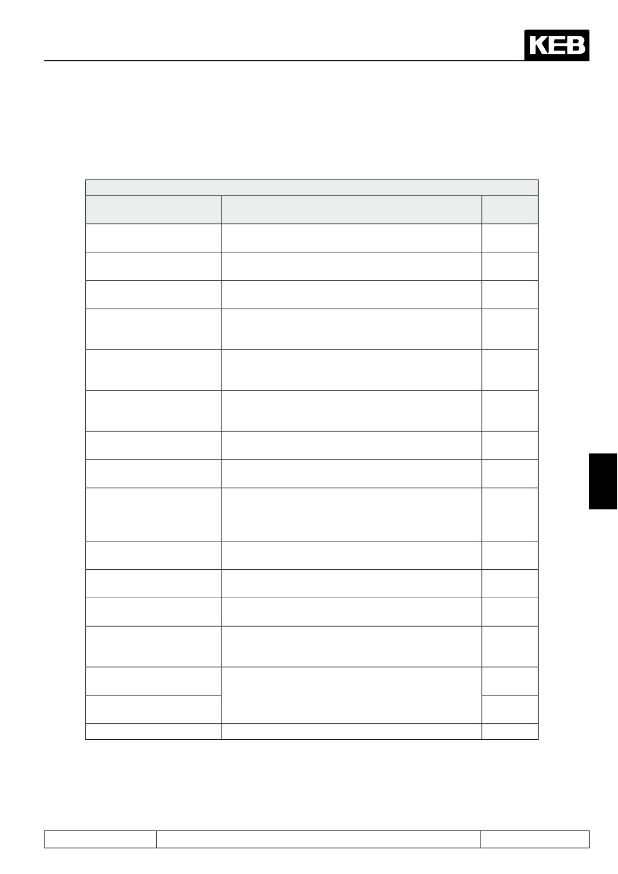
Digital In- and Outputs
The following table shows an overview of the functions that can additionally be assigned to a digital input with
the parameters di.24.. di.35 (only one auxilliary function per input allowed / Bit 31 "I+ Function" must be active
for the input in question):
di.24...di.35 Input "+" function
Value
Explanation
Func.
Para1)
0: Reset master slave
Master position (ru.56) is overwritten with slave positi-
PS.11
difference
on (ru.54)
Current position (ru.54) is overwritten with reference
1: Set reference point
PS.13
position (PS.17)
current position (ru.54) is adopted as target position in
2: Store position (teach)
PS.36
PS.24
in the state "positioning active", the current position
3: Scan position
is stored in ru.71 "Teach/ Scan Position Display" at a
PS.37
positive edge
Rotation setting for relative positioning (only if for
4: Relative position F/R
the positioning target the mode "relative to PS.38" is
PS.38
selected in PS.27)
any digital input receives the function "control release"
5: Software ST (not at
(software emulation / function cannot be connected to
di. 36
di.35)
input ST)
Setting the input leads to locking of the software con-
6: ST locking (not at di.35)
di. 37
trol release
7: Reference point correc-
Connecting the switches for flying referencing in slip-
PS.43
tion
coupled systems
7
Between the end of the break closing period (Pn.40)
and the beginning of the break opening period (Pn.36)
8: Break monitoring
Pn.42
the break always has to be closed. If the input beco-
mes (or is) active during this phase, E.br is triggered.
9: Dead time compensation
While the input is active, dead time compensation is
uF.21
off
switched off
10: UPS operation 400V
Activating the input causes a reduction in the threshold
Pn.78
class
for activation and resetting of the undervoltage error
11: no digital ST (di.35 no
Control release is set only via the terminal strip (di.01 /
di. 39
function)
di.02 and control word SY.43 / SY.50 without function)
Start of the temperature-dependent stator resistance
12: Start autom. Rs tempe-
adjustment (only in v/f-characteristic controlled opera-
dr.61
rature correction
tion and SMM)
13: Encoder channel 2 /
Ec.48
apply value
The value of Ec.32 (at 14: and Ec.31) is sampled with
14: Encoder channel 1 + 2 /
the rising edge and stored in Ec.50/ Ec.51
Ec.49
apply value
15: reserved
1) column "func. param." shows the function-specific parameter corresponding to the value in di.11...di.22
Page7.3 - 11
Digital In- and Outputs
7.3.12Software ST and locking of the control release
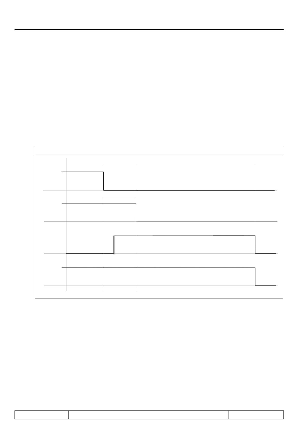
di.36 software ST, di.37 ST lock, di.38 turn off ST delay time
The function is switched off, if no input is selected in di.36. ST can not be selected as software ST or input for
locking.
With the locking function the control release can be controlled in case of voltage failure (even if the controlled
PLC is failure) as long as e.g. Power off function needs for stopping the drive.
Condition: terminal ST must be bridged !
Switching off an input (selection in di.36) is decelerated for the time adjusted in di.38. Within this time the lo-
cking input (selection into di.37) must be active in order to secure the function.
A software input e.g. (IA-ID) can be assigned with the function Power off (do.00...do.07 = 17, switching condi-
tion for OA-OD) as locking input.
Figure 7.3.11c Software ST, locking of the control release
Software ST
input selection
(di.36)
di.38
Turn off ST
delay time
(di.36,38)
ST lock input
selection
(di.37)
Function
software ST
7.3.13Deactivation of the digital control release
With the digital input selection (di.01 / di.02) or the control word (SY.43/ SY.50) the control release can be trig-
gered digitally (e.g., via a bus system). Additionally, terminal ST must always be active.
In parameter di.39, "turn off ST input selection", an input can be selected for deactivating the digital setting of
the control release . Thus, only terminal ST is active.
That way, it is possible to implement manual operation in case of bus system failure.
Page7.3 - 12
Digital In- and Outputs
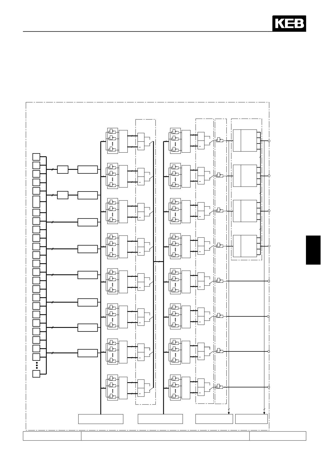
7.3.14Summary description digital outputs
Figure 7.3.12 Principle of the digital outputs
Switching conditions SB0...SB7
Flag 0...7
Outputs O1...OD
do.24
do.41
do.42
do.51
Transistor
do.8
do.25
Bit 0-1
do.16
do.33
20=1
20=1
output
1
1
8
0
O1=O1
1
8
1
1
1
&
&
O1=O2
(O1)
8
2
8
1
2
1
1
8
8
2
O1=R1
X2A.18
>1
>1
1
128
1
128
3
O1=R2
0
4
Transistor
do.9
do.26
do.43
do.0
do.17
do.34
Bit 2-3
31
21=2
output
1
1
21=2
1
1 of 31
1
8
1
8
0
O2=O1
z-1
2
&
(O2)
1
&
1
4
O2=O2
2
8
2
8
2
1
8
8
8
O2=R1
X2A.19
>1
>1
3
1
128
1
128
12
O2=R2
31
do.44
do.1
4
Relay
1 of 31
4
z-1
do.10
do.27
do.18
do.35
Bit 4-5
output
22=4
22=4
5
1
1
8
1
8
1
0
R1=O1
&
4
(R1)
8
1
2
&
8
1
2
16
R1=O2
1
6
X2A.24...26
8
8
>1
32
R1=R1
do.2
>1
31
1
128
1
128
48
R1=R2
7
1 of 31
8
do.11
do.28
4
do.19
do.36
Bit 6-7
23=8
23=8
Relay
9
1
1
8
1
1
8
0
R2=O1
8
output
31
do.3
8
1
2
&
8
1
2
&
64
R2=O2
1
10
(R2)
1 of 31
8
8
128
R2=R1
>1
>1
7
11
1
128
1
128
192
R2=R2
X2A.27...29
8
12
do.12
do.29
do.4
do.20
do.37
24=16
13
31
24=16
1
1
8
1
1
8
1 of 31
16
&
&
Internal
8
1
2
8
1
2
14
1
8
output OA
8
>1
>1
15
1
128
1
128
do.5
16
31
Internal
1 of 31
do.13
do.30
do.21
do.38
output OB
17
25=32
25=32
1
1
1
8
1
8
32
&
&
18
8
1
2
8
1
2
1
8
8
do.6
>1
>1
19
31
1
128
1
128
Internal
1 of 31
20
output OC
do.14
do.31
21
do.22
do.39
26=64
26=64
1
1
8
1
1
8
do.7
64
&
&
22
31
8
1
2
8
1
2
1
Internal
1 of 31
8
8
>1
>1
23
1
128
1
128
output OD
do.15
do.32
91
do.23
7
do.40
2
=128
27=128
1
1
8
1
1
8
128
8
1
2
&
8
1
2
&
1
8
8
>1
>1
1
128
1
128
8
8
ru.23 Output conditi-
ru.24 Status
ru.80 digital
ru.25 Output
on status
of output flags
output state
terminal status
Page7.3 - 13
Digital In- and Outputs
Description
For the switching of the digital outputs one can choose up to 8 conditions from the 91 different conditions.
These are entered in do.00...do.07. Switching condition 0 and 1 can be filtered by do.43 and do.44. Parameter
ru.23 shows, if one or several of these conditions are met.For each flag it can now be selected which of the 8
conditions shall apply to it (do.16...do.23). Each condition can still be inverted before selection (do.08...do.15).
As a standard, all conditions (if several are selected) are OR-operated. With do.24 this can be changed to
AND-operation, i.e. all conditions selected for this flag must be fulfilled before it is set. Parameter ru.24 shows
the flags which are set in this stage. do.33...40 form a second logic step with which a selection of the flags from
logic step 1 can be made. Every individual condition can be inverted with do..25...32. do.41 adjusts the manner
of the linkage (AND/OR). Parameter do.42 is used for inverting one or several outputs. With do.51 the output
signals are assigned to the terminals. ru.80 serves for the display of the status prior to allocation, thereafter
ru.25. The internal outputs OA...OD are directly connected with the internal inputs IA...ID.
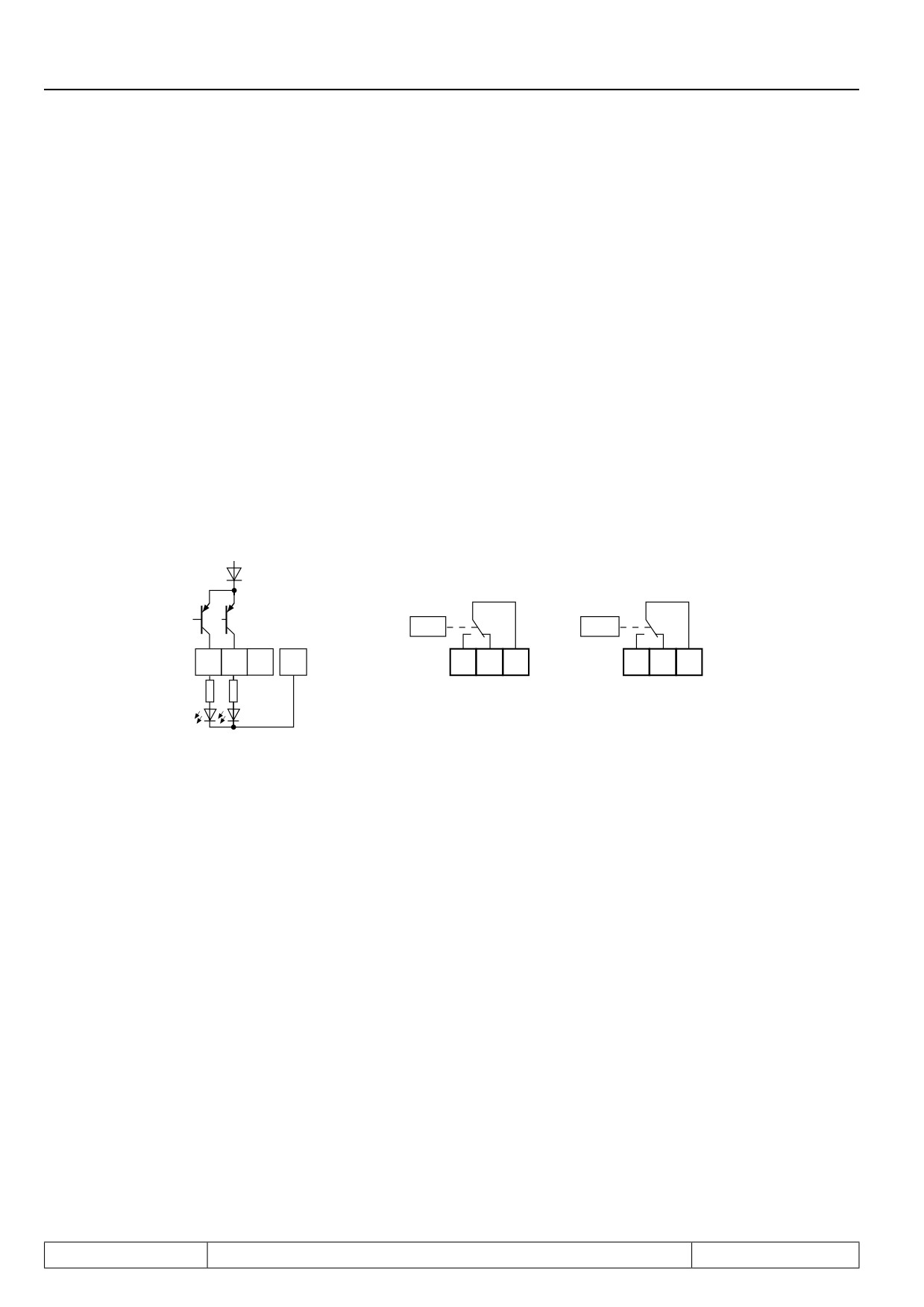
7.3.15Output signals / hardware
Figure 7.3.13a 'Transistor output
Figure 7.3.13b Relay output
The total current of X2A.18, 19 is limited to 50mA. In case of inductive load at the relay outputs or at the tran-
sistor output a protective wiring is to be provided (free-wheeling diode)!
7.3.16Output filter (do.43, do.44)
With do.43 a filter can be set for switching condition 0. With do.44 for switching condition 1. The change of a
switching condition must be applied for the filter time, then it becomes active at the output of the filter. If the
change of a switching condition is cancelled during the filter time, the filter time is reset and restarted at the next
change. The filter time can be adjusted in a range of 0 (off)...1000 ms.
Page7.3 - 14
Digital In- and Outputs
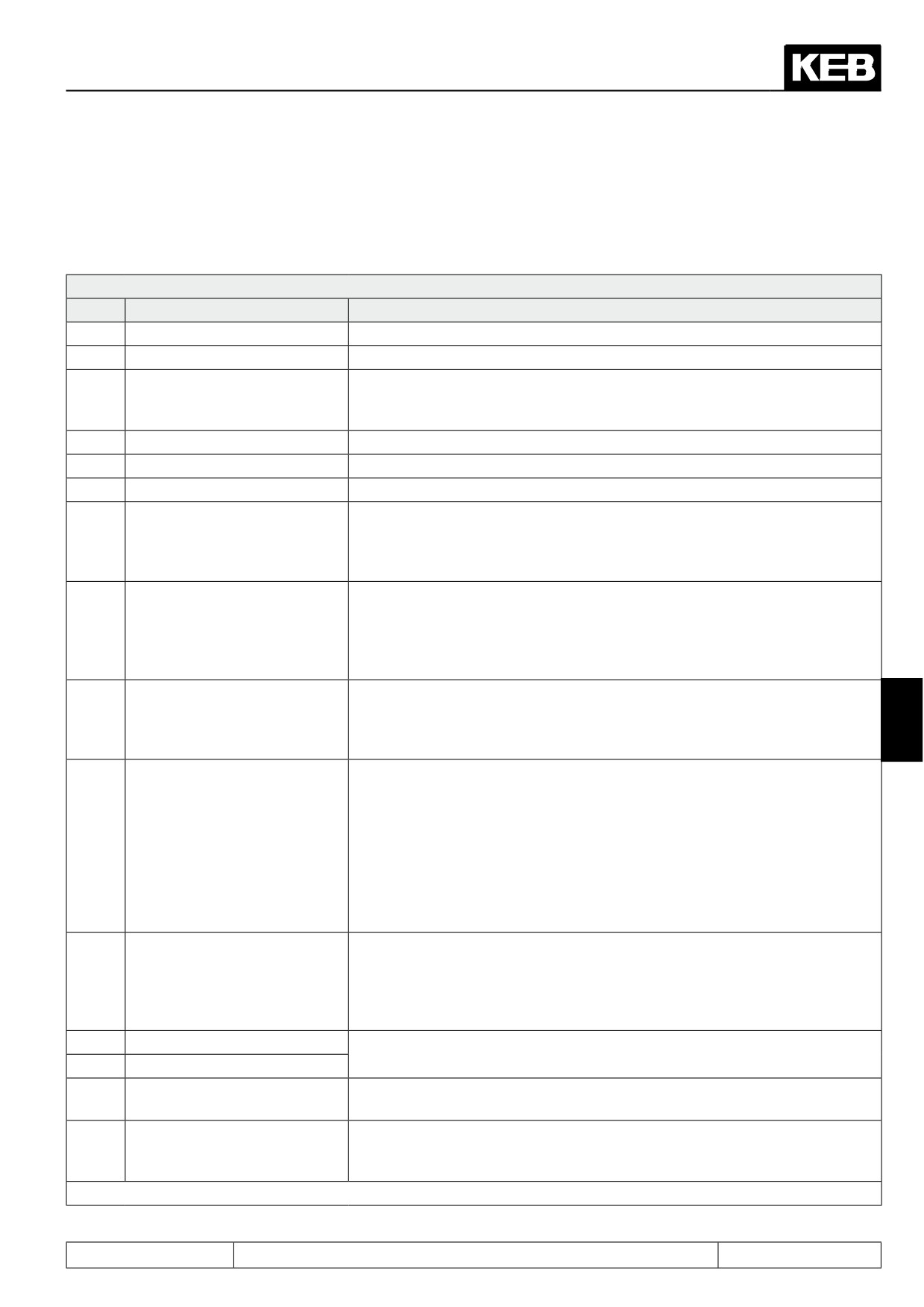
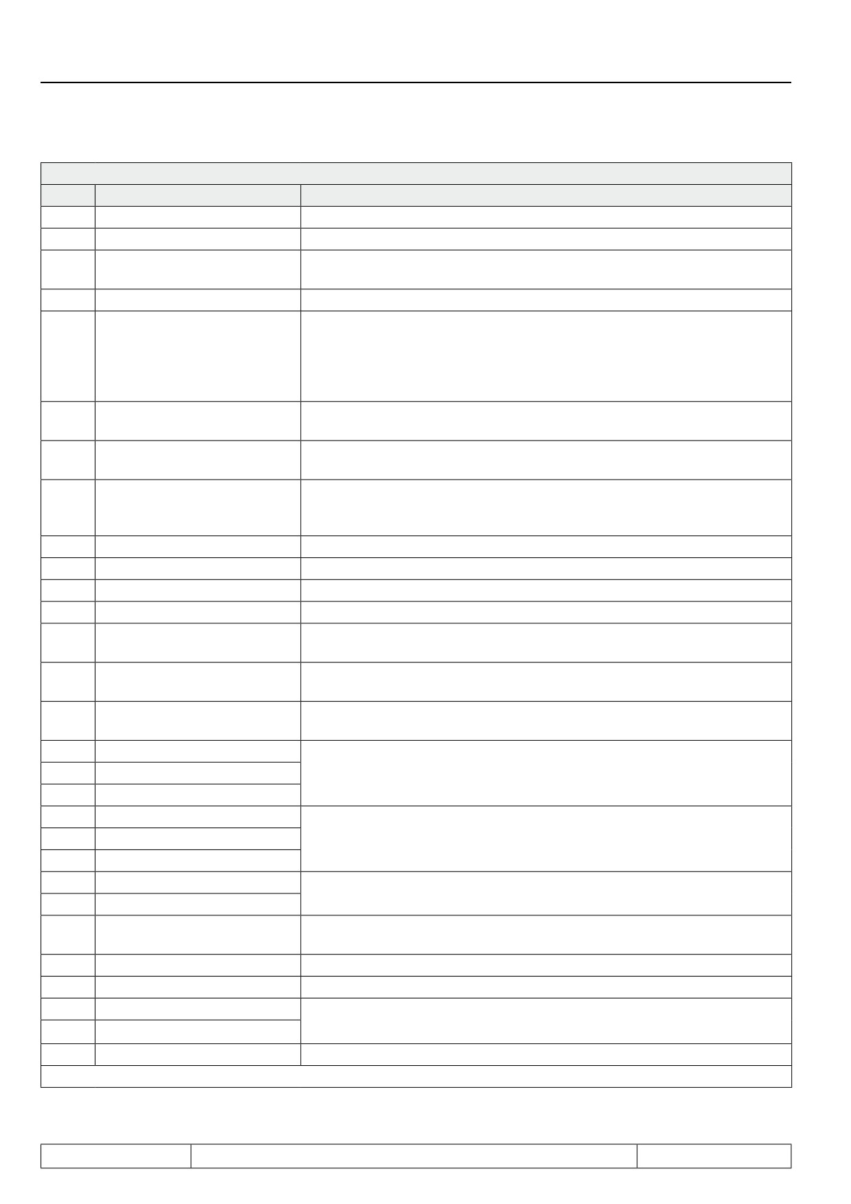
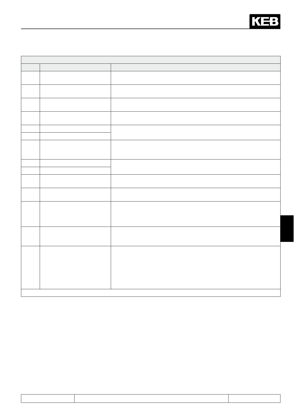
7.3.17Switching conditions (do.00...do.07)
From the following switching conditions one can select up to 8 for further processing. The values are then
entered in the parameters do.00...do.07.
do.00...do.07: Switching conditions
Value
Function
Description
0
Always switched-off
Switching condition never met
1
Always active
Switching condition always met
Drive is running and there is no malfunction (also set when modulation is
2
Run signal;
generally enabled but is temporarily disabled due to, e.g., "motor de-excita-
tion").
3
Ready for operation
Drive is ready for operation (inverter state unequal error).
4
Error
There is an error message (inverter state equals the error).
5
Error without auto-reset
Is not set for errors for which automatic restart is programmed.
ru.39 is an overload counter, counting in steps of 1%. On reaching 100 %
the inverter switches off. Upon exceeding the level of Pn.09 (default 80%)
7
Pre-warning overload
the overload warning is given. The performance in case of a warning can
be adjusted with Pn.08 (response to OL-warning).
Overheating-prewarning (OH)! Depending on the power circuit the inverter
switches off between 60...95°C heat sink temperature. The prewarning is
Pre-warning power module
8
output, when the level OH-warning (Pn.11) is reached (default 70°C). The
overheating
behaviour in case of a warning can be adjusted with Pn.10 (response to
OH-warning).
PTC-prewarning (dOH), on tripping of the motor-PTC connected to the
Pre-warning motor overhea-
terminals T1/T2. After expiration of an adjustable switch-off time Pn.13
9
7
ting
(0...120s) the inverter switches off. The behaviour in case of a warning can
be adjusted with Pn.12 (response to dOH-warning).
F5-M and F5-H (asynchronous motors):
The motor protection trigger time according to VDE has expired. The reac-
tion to the triggering of the electronic motor protection relay can be adjusted
with Pn.14 (motor protection reaction).
10
Motor protection relay function
F5-S and F5-E (synchronous motors):
The overload counter of the motor protection function for servo motors has
exceeded the value of Pn.15 "motor protection function level". When the
counter reaches 100%, the error is triggered. The response to this prewar-
ning can be adjusted with Pn.14 (response to motor protective function).
Interior temperature-prewarning (OHI) is output, when the interior tempera-
ture of the inverter exceeds the level OHI-warning. The behaviour in case of
11
Warning internal overheating
an error can be adjusted with Pn.16 (response to OHI-warning). An error is
generally released after expiration of the OHI-deceleration time (Pn.17). Not
at Pn.16 = 7
12
Cable breakage 4...20mA AN1
Cable breakage for 4...20mA setpoint setting at An.01 or An.02. Triggering
13
Cable breakage 4...20mA AN2
when set point current falls below 2mA.
Pn.20 "current limit level" exceeded (only for v/f characteristic-controlled
14
Current limit ( I > Pn.20 )
operation).
Ramp is stopped (LA-/LD-stop active). Pn.24 "ramp stop current. level" or
15
Load acceleration stop active
Pn.25 "ramp stop intermediate circuit voltage level" exceeded during acce-
leration/deceleration.
further on next side
Page7.3 - 15
Digital In- and Outputs
do.00...do.07: Switching conditions
Value
Function
Description
16
DC-braking active
DC-voltage breaking active
17
Power off function
The inverter state is "power off function active".
The output is used for brake control. The output is active if the brake is to
18
Brake control
be ventilated.
19
System deviation > level
ru.02 "ramp output display" - ru.07 "actual value display" > switching level
Is set if parameter ru.07 "actual value display" falls into a window of +/-
LE.16 "freq./speed hysteresis" around ru.01 "set value display". Not set
20
Speed dependent
when the state is "no control release" or "idle". If the ramp generator is
deactivated by a different function (e.g., positioning, speed search, DC bra-
king, etc.), the state of the switching condition is undefined.
Ramp generator is in the phase acceleration, clockwise rotation, accelerati-
21
Acceleration
on, counter clockwise rotation, or acceleration stop.
Ramp generator is in the phase deceleration, clockwise rotation, decelerati-
22
Deceleration
on, counter clockwise rotation, or deceleration stop.
The rotation directions at the input and output of the ramp generator are
Real direction of rotation = set
23
equal (the sign of ru.02 "ramp output display) is identical with the sign of
direction of rotation
ru.01 "set value display").
24
Utilization > level
Utilization (ru.13) > level
25
Abs. active current > level
Abs. active current (ru.17) > switching level
26
DC link voltage > level
DC-link voltage (ru.18) > level
27
Actual value > level
Abs. actual value (ru.07) > switching level
Abs. set value (ru.01) > switching level (applies only if the ramp generator
28
Set value > level
is active)
Approach to reference point
Approach to reference point executed and completed (position valid/ soft-
29
finished
ware limit switch useable)
Current torque > switching level (not in v/f-characteristic-controlled operati-
30
Current torque > level
on)
31
Absolute value AN1 > level
Absolute value of AN1 / AN2 / AN3 at the output of the characteristic ampli-
32
Absolute value AN2 > level
fier > switching level
33
Absolute value AN3 > level
34
AN1 > level
AN1 / AN2 / AN3 at the output of the characteristic amplifier > switching
35
AN2 > level
level (with sign evaluation)
36
AN3 > level
37
Timer 1 > level
ru.43 "timer 1 display" respectively ru.44 "timer 2 display"
> switching level
38
Timer 2 > level
Absolute value of ru.58 "angle difference" > switching level (only in posi- or
39
Angle difference > level
synchro-mode / note the scaling factor of the LE-parameter for increments)
40
Hardware current limit active
Protection function "hardware current limitation" is active
41
Modulation on
set if modulation is active
42
ANOUT3 PWM
Output of the analog signal ANOUT 3 and ANOUT 4, respectively, as PWM
43
ANOUT4 PWM
signal. The cycle duration is set with An.46 and An.52, respectively.
44
Inverter state (ru.0) = level
Number of the inverter state (e.g. 18 at error! Watchdog) = switching level
further on next side
Page7.3 - 16
Digital In- and Outputs
do.00...do.07: Switching conditions
Value
Function
Description
Power module temperature
45
Power module temperature (ru.38) > switching level
(ru.38) > level
Motor temperature (ru.46) >
46
Motor temperature (ru.46) > level
level
Ramp output display (ru.2) >
47
Abs. ramp output display (ru.02) > switching level
level
Apparent current (ru.15) >
48
Apparent current (ru.15) > Level
level
49
clockwise rotation
current rotation direction clockwise rotation and counter clockwise rotation,
50
counter-clockwise rotation
respectively (only set if ramp generator is active.
Upon exceeding the level of Pn.09 (default 80%) the overload warning OL2
51
OL2 warning
is given. The performance in case of a warning can be adjusted with Pn.8
(response to OL-warning).
52
Current regulator limit reached
Current and speed controller, respectively, in the limit (not in v/f-characteri-
53
Speed control at the limit
stic-controlled operation).
The position profile is completed (ru.56 = ru.61) and the drive is in the ran-
54
Target window reached
ge of +/- PS.30 / 2 (target window) around the target position ru.61.
ru.54 "current position" > switching level (note the scaling factor of the level:
55
Current position > level
1,00 = 100 increments).
Positioning is active, but the set position ru.56 has not yet reached the
target position ru.61. The output is deactivated as soon as the calculated
56
Positioning active
position profile has reached the target position (ru.56 "set position" = ru.61
"target position"), even if the drive has not reached the target window yet.
The position is inaccessible from the current speed under the restrictions
7
57
Position not reachable
of the adjusted deceleration and S-curve times or a new "start positioning"
command was sent during the deceleration ramp.
This output switching condition is needed for the follow-up positioning.
The output is set if all selected inputs coupled add up to 1. Relevant for the
coupling is the internal status of the inputs (displayed in ru.22 "internal input
58
Profile processing active
status").
The output is set with "start positioning" and deactivated only if ru.56 "set
position" has reached the target position of the last block. (in the parameter
PS.26, "index/ next", of the last block, the value must be " -1: PS.28").
further on next side
Page7.3 - 17
Digital In- and Outputs
do.00...do.07: Switching conditions
Value
Function
Description
59
Inputs AND-connected (ru.22)
Function
switching condition met if:
60
Inputs OR-connected (ru.22)
and
all selected inputs active
Inputs NAND-connected
or
at least one selected input active
61
(ru.22)
NAND
at least one selected input inactive
NOR
all selected inputs inactive
The selection of the inputs to be coupled is done with the switching level
parameter LE.00...LE.07.
62
Inputs NOR-connected (ru.22)
Input
ST
RST
F
R
I1
I2
I3
I4
IA
IB
IC
Id
Value
1
2
4
8
16
32
64
128
256
512
1024
2048
The sum of the inputs to be queried is entered in the switching levels.
Example: If R and I1 are to be coupled for switching condition 0 F, LE.00
must be set to 4 + 8 + 16 = 28,00.
Absolute value ANOUT1 >
63
Absolute value of ANOUT1 (absolute value of ru.34 "display ANOUT1 after
switching level
amplification) or ANOUT2 (absolute value of ru.36 "display ANOUT2 after
Absolute value ANOUT2 >
64
amplification) greater than the switching level
switching level
65
ANOUT1 > Level
ANOUT1 (ru.34 "display of ANOUT1 after amplification) or ANOUT 2 (ru.36
66
ANOUT2 > Level
"display of ANOUT2 after amplification) greater than the switching level
path traversed since the last "start positioning" command is greater than the
67
traversed path > level (Posi)
adjusted level. If the positioning is complete, the output is reset.
Position to target window >
The output is set, if the distance to be covered to the target is larger than
68
level (Posi)
the adjusted level.
Ext. PID system deviation >
absolute value of the system deviation of the external PID-controller > swit-
69
level
ching level
For inverters with safety relays: The driver voltage for the activation of the
70
Driver voltage active
power module is active.
synchronization period after activation of the synchronization run is com-
71
Drive runs synchronously
pleted (no display of existing angle synchronicity between slave and ma-
ster)
ru. 60 "current position index" is equal to the switching level (scaling factor:
72
Actual position index = level
values of 0.51...1.5 count as index 1 etc.)
73
Abs. active power > level
Abs. ru.81 "active power" > switching level
74
Active power > level
ru.81 "active power" > switching level
Amount act. position - scan
ru.54 "actual position" - ru.71 "teach/scan position display" > switching
75
position > level
level
76
reserved
Act. position = position index
ru.60 "actual position index" = PS.28 "start index new profile" and target
77
PS.28
window of this positioning reached
During the flying referencing in a round table application, a reference
78
Rotary table reference invalid
signal outside of the position window of +/- PS.40 "reference point window"
around the reference point has been recognised.
further on next side
Page7.3 - 18
Digital In- and Outputs
do.00...do.07: Switching conditions
Value
Function
Description
The output is set if a "start positioning" command was ignored because the
79
Ignore position not reachable
new target position is "inaccessible". The output is reset by a new "start
positioning" command or by deactivation of the Posi mode.
ru.17 "active current" greater than the switching level (sign of ru.17 is taken
80
Active current > level
into account).
81
Actual value channel 1 > level
Abs. ru.09 "encoder 1 speed" respectively ru.10 "encoder 2 speed" > swit-
82
Actual value channel 2 > level
ching level.
83
HSP5 bus synchronised
HSP5 bus synchronised;corresponds status word bit 9 (SY.51)
absolute value of ru.07 "actual value display" is smaller than oP.06 "min.
Act. value < min. setpoint
84
reference forward" in clockwise rotation or oP.07 "min. reference reverse" in
oP.06 / 07
counter clockwise rotation.
The input triggering "warning! external input" or "error! external input" is
85
ABN. Ext. error
active (the inverter state has no effect).
The Watchdog (HSP5 Watchdog SY.09 or operator Watchdog Pn.06) has
86
ABN. Watchdog
triggered (inverter state has no effect).
The acceleration has exceeded the value of parameter Pn.79 "acceleration
limit of 1/s^2".
Pn.80 "acceleration scan time" determines the time period used for accele-
87
ABN. Acceleration
ration averaging.
For the calculation, the speed difference must be converted from 1/min to
1/s. *
Pre-warning level for an overload protection function that monitors the mo-
tor and the inverter has been exceeded. This switching condition combines
(OR-operation) the warning messages 7(OL), 8(OH), 9(dOH), 11(OHI),
7
10(OH2), 51(OL2) .
88
ABN. Power circuit and motor
Additionally, this switching condition has the following function: If "automatic
restart E.UP" is activated in Pn.00 and a time limit for the restart function
in Pn.76, "max. E.UP warning time", is set, then the switching condition is
active during the warning time (i.e., the time in which an automatic restart
would be executed).
ru.07 "actual value display" is smaller than switching level / 100 x ru.02
Actual value < level x set
89
"ramp output display". This switching condition is inactive if modulation is
value
switched off and for special functions like speed search.
Motor temperature for Rs corr.
The switching condition is met if the motor temperature for the RS-correc-
90
(dr.51) > level
tion (dr.51) is greater than the switching level.
If the setting "warning" is programmed in Ec.42, "encoder alarm mode", the
91
ABN. Encoder
"error! encoder" is not triggered. A warning signal can be generated via this
switching condition instead.
Speed change during scan time
* Acceleration =
————————————————————
60 x scan time (in seconds)
Switching level 0...7, LE.00...LE.07
These parameters define the levels of the switching conditions.
Level 0 (LE.0) applies for switching condition 0; LE.1 for switching condition 1 ... and so forth.
Page7.3 - 19
Digital In- and Outputs
Switching hysteresis 0...7, LE. 08...LE.15
The hysteresis, in reference to the adjusted values, defines the parameters LE. 08...LE.15.
Hysteresis 0 (LE.08) applies for comparison level 0; LE.09 for comparison level 1 ... and so forth.
Frequency hysteresis LE.16
LE.16 determines the hysteresis for status constant run.
7.3.18Inverting of switching conditions for flags 0...7 (do.08...do.15)
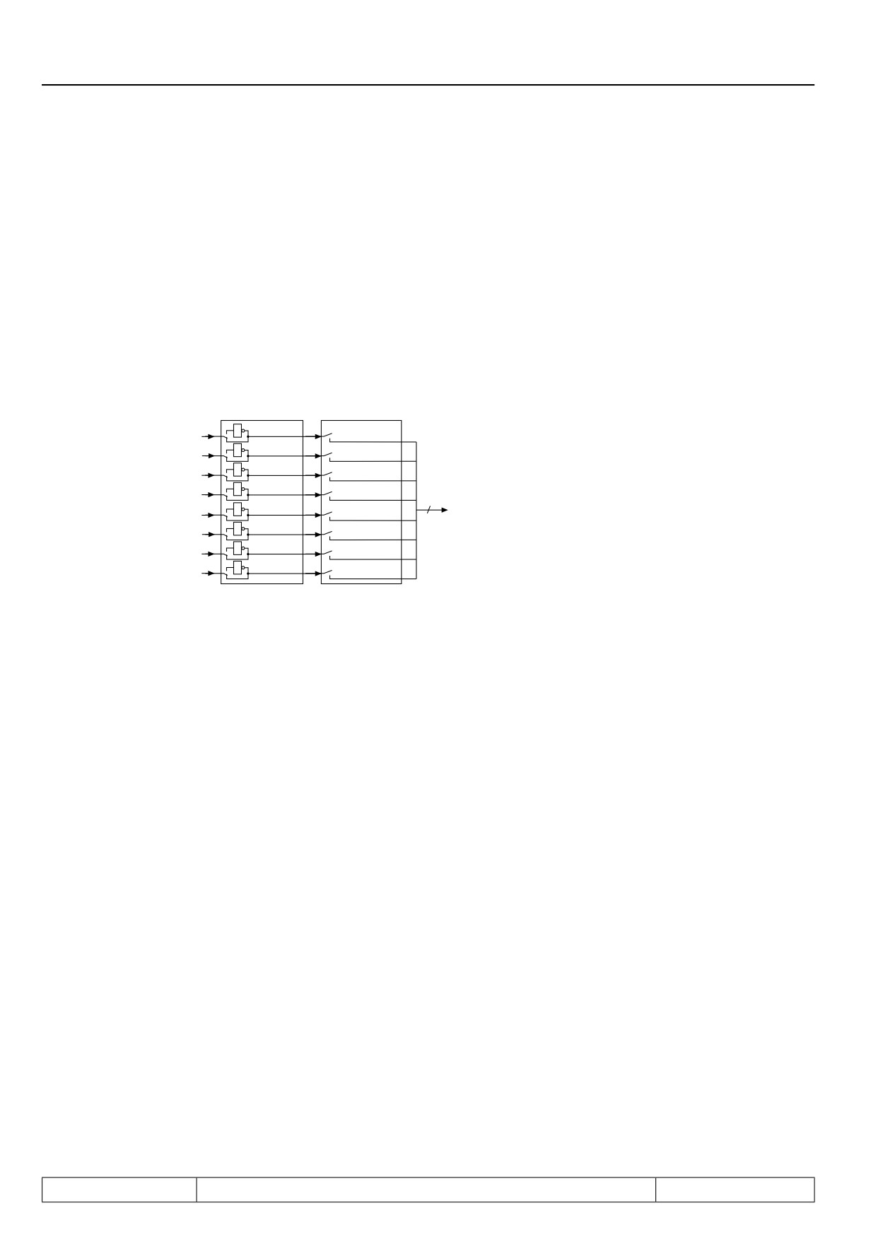
Figure 7.3.15 Inversion and selection of switching conditions
do.8...do.15
do.16...do.23
1
1
1
do.0
1
2
2
do.1
1
4
4
do.2
1
8
8
do.3
8
1
16
16
do.24
do.4
1
32
32
do.5
1
64
do.6
64
1
128
do.7
128
With the parameters do.08...do.15 each of the 8 switching conditions (do.00...do.07) can be inverted for each
flag separately. Through this function it is possible to set any chosen switching condition as Non-condition.The
parameter is bit-coded.According to Fig. 7.3.15 the weighting of the switching conditions to be inverted must be
entered in do.08...do.15. If several conditions shall be inverted, the sum is to be formed.
Example:
Output X2A.19 shall be set when the inverter is not accelerating! In this case we assign the switching condition
21 (inverter accelerates) for example to do.01 (enter value 21). We invert the switching condition (do.01) with
do.09, so enter value 2.
7.3.19Selection of switching conditions for flags 0...7 (do.16...do.23)
The parameters do.16...do.23 serve for the selection of the 8 defined switching conditions. The selection is
done for each flag separately, where one can choose between no one and up to all 8 switching conditions.
According to Fig. 7.3.15 the weighting of the selected switching conditions is to be entered into do.16...do.23.
If several conditions shall be inverted, the sum is to be formed.
7.3.20Linking the switching conditions for flags (do.24)
After the switching conditions are selected for each output, it can now be determined, how these are linked.
As a default all conditions are OR-operated, i.e. if one of the selected conditions is met, the flag is set. Another
possibility is the AND-operation which can be adjusted with do.24. AND-operation means that all selected con-
ditions must be fulfilled before the flag is set.
Parameter do.24 is bit-coded. The table under 7.3.17 shows the assignment.
Page7.3 - 20
Digital In- and Outputs
Figure 7.3.20 Linking the switching conditions in logic step 1
do.24
8
do.16
&
1
Bit 0
Flag 0
>1
0
8
do.17
&
1
Bit 1
Flag 1
>1
0
8
do.23
&
1
Bit 7
Flag 7
>1
0
7.3.21Inverting of flags (do.25...do.32)
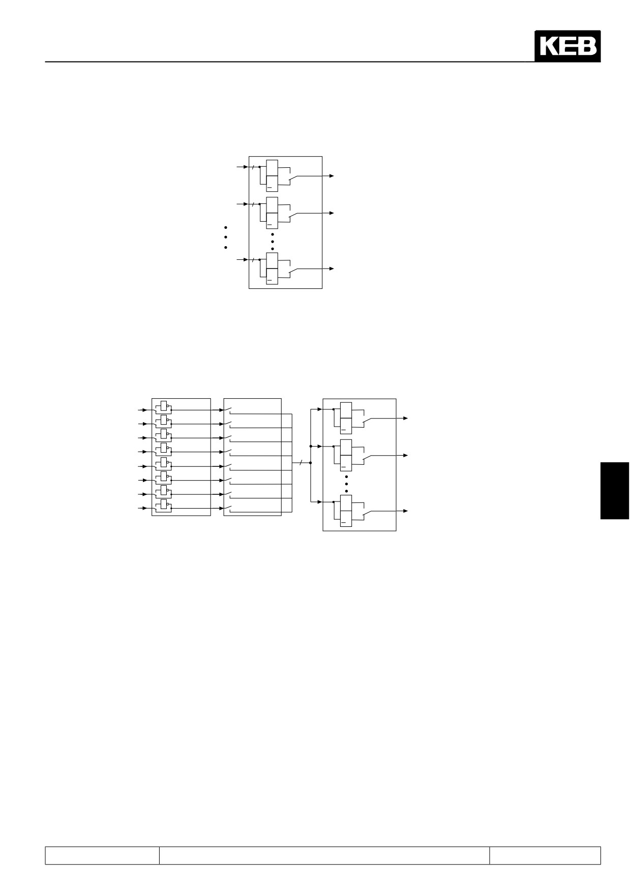
Figure 7.3.21 Inversion and selection of flags
DO
DO
DO
DO
DO
"IT
"IT
/
"IT
"IT
"IT
"IT
/
"IT
"IT
"IT
7
"IT
"IT
/$
With the parameters do.25...do.32 each of the 8 flags (bit 0...7) from logic step 1 can be inverted separately.
Through this function it is possible to set any chosen flag as Non-flag. The parameter is bit-coded. According
to Fig.7.3.18 the weighting of the flag to be inverted must be entered in do.25...do.32. If several flags shall be
inverted, the sum is to be formed.
7.3.22Selection of flags (do.33...do.40)
In the second logic step a selection of the flags of the first logic step can be made.The selection is done for
each output separately, where one can choose between no one and up to all 8 flags.According to Fig. 7.3.18
the weighting of the selected flags is to be entered into do.33...do.40. If several flags shall be inverted, the sum
is to be formed.
Page7.3 - 21
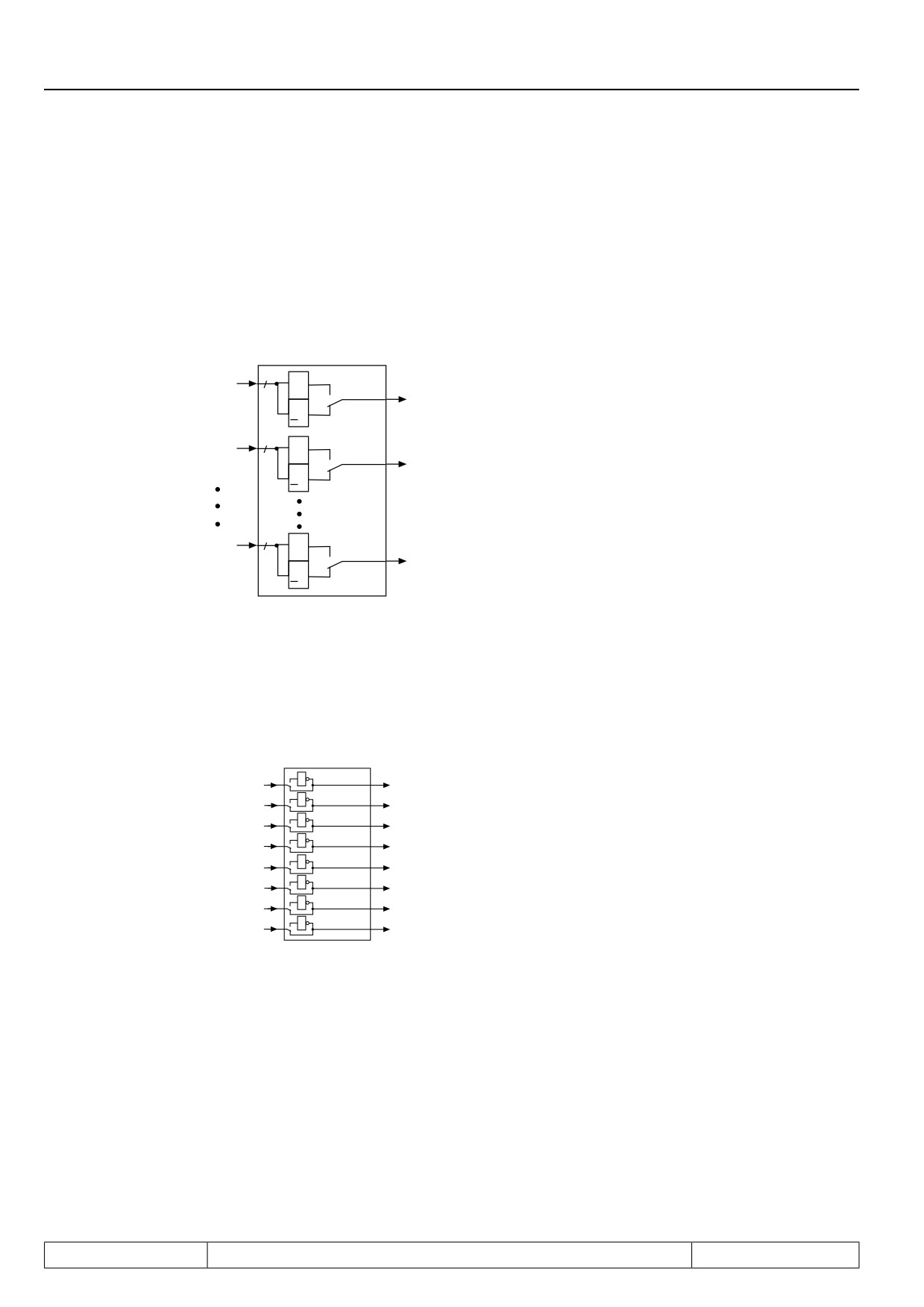
Digital In- and Outputs
7.3.23Linking the flags(do.41)
After the switching conditions are selected for each output, it can now be determined, how these are linked. As
a default all flags are OR-operated, i.e. if one of the selected flags is met, the output switches.Another possibi-
lity is the AND-operation which can be adjusted with do.41. AND-operation means, that all selected flags must
be set before the output switches.
Figure 7.3.23a. Linking the outputs
do.41
8
do.33
&
1
Bit 0
O1
>1
0
8
do.34
&
1
Bit 1
O2
>1
0
8
do.40
&
1
Bit 7
OD
>1
0
As shown in Fig. 7.3.23b, with parameter do.42 the outputs can be once again inverted after the linking. The
parameter is bit-coded, i.e. according to following table the value belonging to this output must be entered. If
several outputs shall be inverted, the sum is to be formed.
Figure 7.3.23b. Inversion of Outputs
do.42
1
1
Bit 0
1
2
Bit 1
1
4
Bit 2
1
8
Bit 3
do.41
1
16
Bit 4
1
32
Bit 5
1
64
Bit 6
1
128
Bit 7
Page7.3 - 22
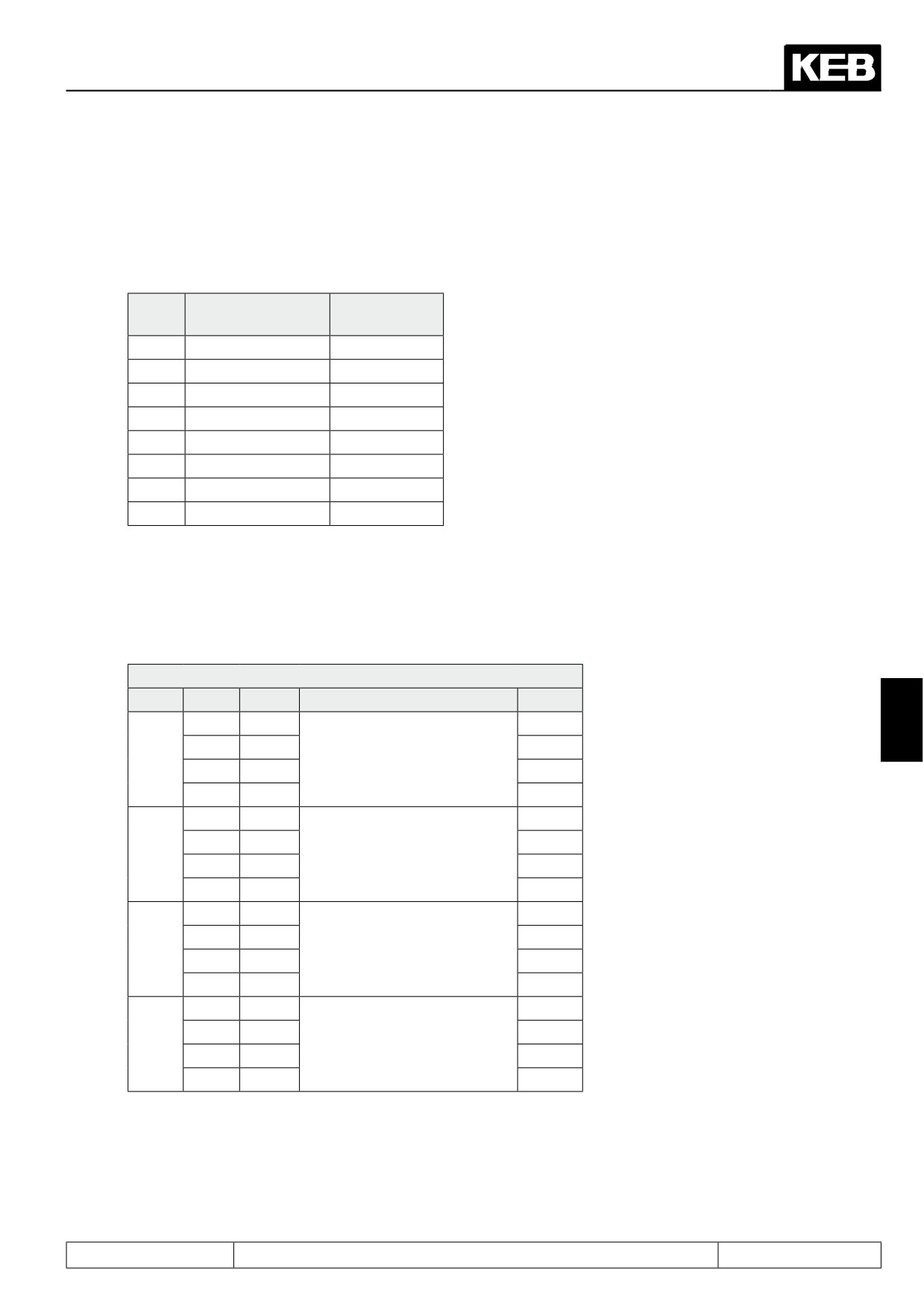
Digital In- and Outputs
7.3.24Output terminal state (ru.25) and digital output state (ru.80)
Parameter ru.25 indicates the logic condition of the digital outputs after the allocation by do.51. Parameter ru.80
indicates the logic condition before the allocation. If an output is set the appropriate decimal value according to
the table below, is output. If several outputs are set, then the sum of the decimal values is output.
Name
Function
Decimal va-
lues
O1
Transistor output
1
O2
Transistor output
2
R1
Relay output
4
R2
Relay output
8
OA
Internal output
16
OB
Internal output
32
OC
Internal output
64
OD
Internal output
128
7.3.25Hardware output allocation (do.51)
With do.51 the output signals are assigned to the output terminals O1, O2, R1 and R2. The assignment is done
according to following table:
do.51: Hardware output allocation
Bit
Value
Signal
Output
Default
0
O1
x
7
1
O2
0 + 1
O1 (terminal X2A.18)
2
R1
3
R2
0
O1
4
O2
x
2+3
O2 (terminal X2A.19)
8
R1
12
R2
0
O1
16
O2
4+5
R1 (terminal X2A.24...26)
32
R1
x
48
R2
0
O1
64
O2
6+7
R2 (terminal X2A.27...29)
128
R1
192
R2
x
Page7.3 - 23
Digital In- and Outputs
7.3.26Programming example
For a better understanding, the correlations are explained on the basis of a little more complex example.Following
conditions are required:
•
Condition 1: Output X2A.19 switches, if the inverter accelerates
•
Condition 2: Relay X2A.24...26 switches, if the inverter load is > 100 %
•
Condition 3: Relay X2A.27...29
•
Output X2A.18 switches, if the conditions 2 and 3 are realised, but the inverter does not accelerate.
Solution proposal:
Set switching conditions, levels and hysteresis
First set the switching conditions and levels.
Set do.00 to "21" (inverter accelerates)
Set do.01 to "24" ((inverter utilization > level); set LE.01 to "100" (load level for do.01 100 %); set LE.09 to "5"
(5 % hysteresis for level 1; not required but reasonable for optimal switching performance).
Set do.02 to "27" (actual value > level); set LE.02 to "4" (frequency level for do.02); set LE.10 to "0,5" (0.5 Hz
hysteresis for level 2;not required but reasonable for optimal switching performance).
Select switching conditions
Set do.16 to "1" (evaluate switching condition of do.0)
Set do.17 to "2 (evaluate switching condition of do.1)
Set do.18 to "4" (evaluate switching condition of do.2)
Set do.8, do.9 and do.10 to "0" (no inverting)
The setting of do.24 is independent for this example, as only one condition each is set at do.16...18.
Set flags
Output O1 (terminal X2A.18)
Set do.33 to "7"(evaluate flags 1...3)
Set do.25 to "1"(flag 1 is inverted, it means that the condition is fulfilled if the inverter does not accelerate).
Set do.41 to "1" (the flags selected with do.33 become AND-operated)
Output O2 (terminal X2A.19)
Set do.34 to "1" (evaluate flag 3)
Set do.26 to "0" (no inverting)
The setting of do.41 is independent for this example, as only one flag is set at do.34.
Relay output R1 (terminal X2A.24...26)
Set do.35 to "2"(evaluate flag)
Set do.27 to "0" (no inverting)
The setting of do.41 is independent for this example, as only one flag is set at do.35.
Relay output R2 (terminal X2A.27...29)
Set do.36 to "4"(evaluate flag)
Set do.28 to "0" (no inverting)
The setting of do.41 is independent for this example, as only one flag is set at do.36.
Page7.3 - 24
Setpoint-, Rotation- and Ramp Adjustment
7.1
Operating and appliance data
1.
Introduction
7.2
Analog in- and outputs I
2.
Summary
7.3
Digital in- and outputs
3.
Hardware
7.4
Setpoint-, rotation- and ramp adjustment
Motor data and controller adjustments of the asynchronous
7.5
4.
Operation
motor
Motor data and controller adjustments of the synchronous
7.6
motor
Selection of Operating
5.
Mode
7.7
Speed control
6.
Initial Start-up
7.8
Torque display and -limiting
7.9
Torque control
7.
Functions
7
7.10
Current control, -limiting and switching frequencies
8.
Error Assistance
7.11
Speed measurement
9.
Project Design
7.12
Positioning and synchronous control
7.13
Protective functions
10. Networks
7.14
Parameter sets
11. Parameter Overview
7.15
Special functions
12. Annex
7.16
CP-Parameter definition
Page7.4 - 1
Setpoint-, Rotation- and Ramp Adjustment
7.4.1
Summary description
7.4 - 3
7.4.2
Reference source oP.00
7.4 - 4
7.4.3
Rotation source oP.01
7.4 - 7
7.4.4
Fixed frequencies (oP.18...23)
7.4 - 11
7.4.5
Setpoint limits
7.4 - 13
7.4.6
Setpoint calculation
7.4 - 15
7.4.7
Ramp generator
7.4 - 16
7.4.8
acc dec mode
7.4 - 20
7.4.8.1
Ramp with constant ascent
7.4 - 20
7.4.8.2
Ramp with constant time
7.4 - 20
7.4.8.3
Ogive run
7.4 - 23
Page7.4 - 2
Setpoint-, Rotation- and Ramp Adjustment
7.4
Setpoint-, rotation- and ramp adjustment
7.4.1
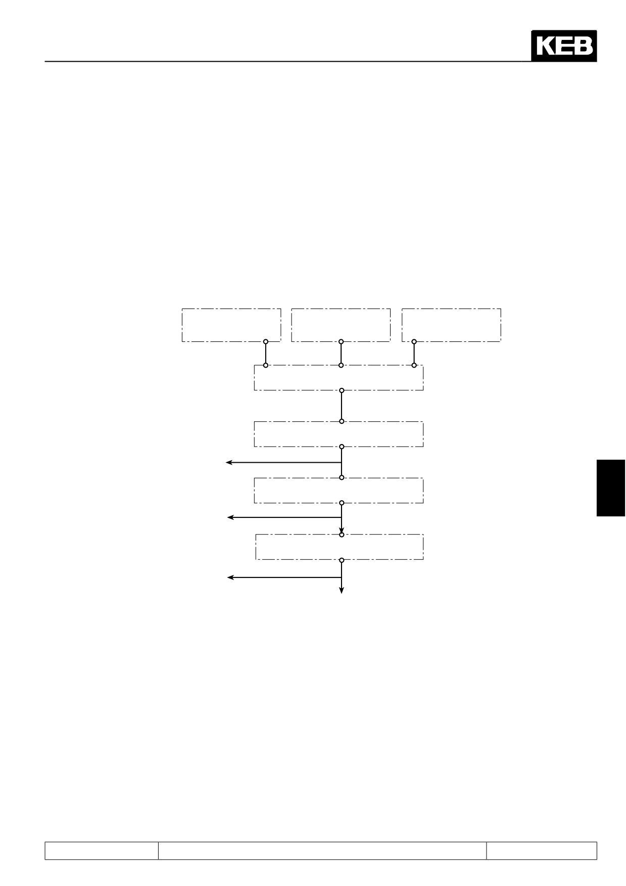
Summary description
The setpoint of the KEB COMBIVERT F5 can be preadjusted analog as well as digital. The AUX-function adds
or multiplies an analog setpoint to/with other setpoint settings.
The setpoint and rotation selection links the different setpoint sources with the possible sources of rotation
direction. The signal thus obtained is used for further setpoint calculation.
Only after interrogation of the absolute setpoint limits, all the data that is required for the ramp calculation is
available.
Fig. 7.4.1
Principle of setpoint and ramp adjustment
Rotation
Interface selection
Fixed frequencies
selection
Setpoint limits
Setpoint calculation
ru.01: Set value display
Set value display
before ramp
Ramp generator
7
ru.02: Ramp output display
Set value display
after ramp
control
ru.03: Actual frequency display
Page7.4 - 3
Setpoint-, Rotation- and Ramp Adjustment
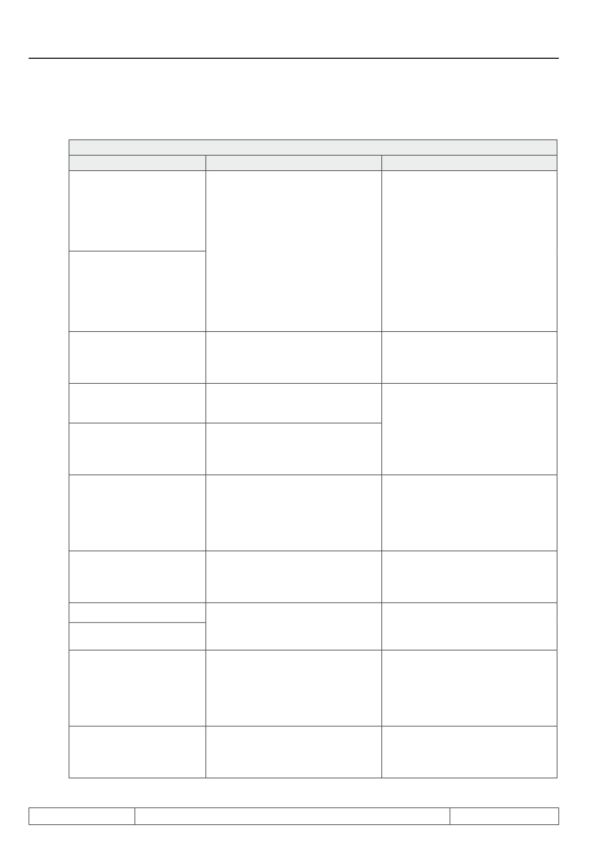
7.4.2
Reference source oP.00
oP.00: Reference source
Value
Function
Notice
Setting the speed setpoint via the
REF or AUX-input 0% correspond to
the "minimum setpoint"
The selection of a hardware analog
0: Analog input REF
(oP.06 at clockwise rotation / oP.07 at
input as REF input is done via para-
counter clockwise rotation)
meter An.30 "Selection of REF Inp../
+100% corresponds to "maximum
AUX Fct" factory setting: AN1 is the
setpoint" (oP.10 at clockwise rotation /
REF input.
oP.11 at counter clockwise rotation)
The selection of how the AUX input
If the rotation direction is determined
value is calculated is also done via
by the sign of the setpoint, then posi-
An.30.
1: Analog input AUX
tive values and 0 represent clockwise
Default: AN2 is the AUX input.
rotation, negative values represent
counter clockwise rotation.
The value range and the resolution
The value of oP.03 "reference setting"
depend on the setting of the speed
2: Digital absolute (op.3)
is used as speed setpoint.
mode in parameter ud.02 "control
type".
The percentage value in oP.05 "refe-
3: Digital in % (op.5)
rence setting %" is used for the speed
Calculation of the speed setpoints
setpoint.
from the percentage value is done the
The percentage value oP.52 "motor
same way as for the REF and. AUX
4: Motor poti actual value
poti value" is used as the speed set-
inputs.
(ru.37)
point (for more on motor potentiome-
ter function see chapter 7.15).
Value range: +/- 32000 rpm
Resolution: 1 rpm
The value of SY.52 "set speed value"
Exception: In the high frequency
5: Set speed value (sy.52)
is used as the speed setpoint.
modes up to 64000 and 128000 rpm,
respectively, different values apply
(see chapter 5.1)
The percentage output value of the
Calculation of the speed setpoints
6: Ext. PID output display
PID-controller (ru.52 "ext. PID output
from the percentage value is done the
(ru.52)
display ") is used as the speed set-
same way as for the REF and AUX
point.
inputs.
7: Speed Measurement 1
The speed measured by encoder
channels
1 and 2, respectively, is
8: Speed Measurement 2
used as the speed setpoint.
Setting of the speed setpoints via
AN1. Setting of the setpoint of the
Modified calculation of the setpoint
speed controller from the analog va-
9: AN 1 direct (+/- 10V)
and limitations in the settings options,
lue is done with a fast scanning grid,
see instructions.
therefore, some limitations in the set-
tings options have to be accepted.
Setting of the speed setpoint via oP.63
Configuration of the high resolution
10: High resolution in %
"reference value high-resolution". This
and calculation of the speed setpoint
(ru.63)
mode must be used if the standard
from parameters oP.63 / oP.64 see in-
speed resolution is insufficient.
structions.
Page7.4 - 4
Setpoint-, Rotation- and Ramp Adjustment
Other functions like quick stop, fixed frequency, or positioning have priority over "standard operation" and can
therefore lead to different speed setpoints than selected in oP.00 .
The following speed setpoint limiting blocks can change the setpoint.
Direct analog setpoint setting (AN1 direct)
The cycle time of the software is 1 ms. During this time the analog input/output status is updated once. Addi-
tionally the inverter requires a processing time of 1... 3 ms before the new setpoint value is calculated. If the
inverter is used as secondary final control element of a superior control, this time can impair the dynamics of
the entire closed-loop control system.
In such cases the analog setpoint value can be processed directly to the control processor (direct setpoint ad-
justment). Thus a sampling time of 250 µs is possible.To enable this fast response to an analog setpoint value,
some restrictions must be accepted:
• The calculation formula of the analog setpoint value changes. The parameters oP.06 / oP.07 are without
influence on the setpoint calculation.
percentage analog value = (analog value/10V x 100% - An.06) x An.05
This value is limited to +/- 100%.
set = limited analog value in percent x oP.10
n
This value is limited with oP.14 for both directions of rotation.
• The setpoint limitations oP.06 / oP.07 / oP.11 do not have any function; the frequency setpoint is only limited
by oP. 14 (for both directions).
• The acceleration / deceleration and S-curve time have no effect; it is operated internally without ramps.
• The parameters An.01...04 and An.07...09 are without any function.
• The stop position controller cannot be activated.
7
High resolution reference setting
The setpoint setting with the settings oP.00 = 0...9 is 16 Bit wide. This results in a maximum resolution of 0.125
rpm in 4000-rpm-mode (ud.02 = 4 and 8).
For applications needing a higher resolution, the high resolution setpoint setting was introduced. Here, the
setpoint is set as a 32-Bit-value.
Since only a 16-Bit-value can be output, the low-order 16 bits of the ramp output value are upsampled. On
overrun, the base value is increased for one cycle (1 ms) (by 0.125 rpm in 4000-rpm-mode). These setpoint
fluctuations are smoothed mechanically, leading to the higher average resolution.
To achieve the highest possible resolution for the application, two parameters can be used:
oP.64 Relative value high-resolution
The parameter oP.64 sets the reference value of the calculation and is dependent on ud.02.
Page7.4 - 5