KEB COMBIVERT F5-A,-E,-H 4.0. APPLICATION MANUAL (2008) - page 6
Analog In- and Outputs I
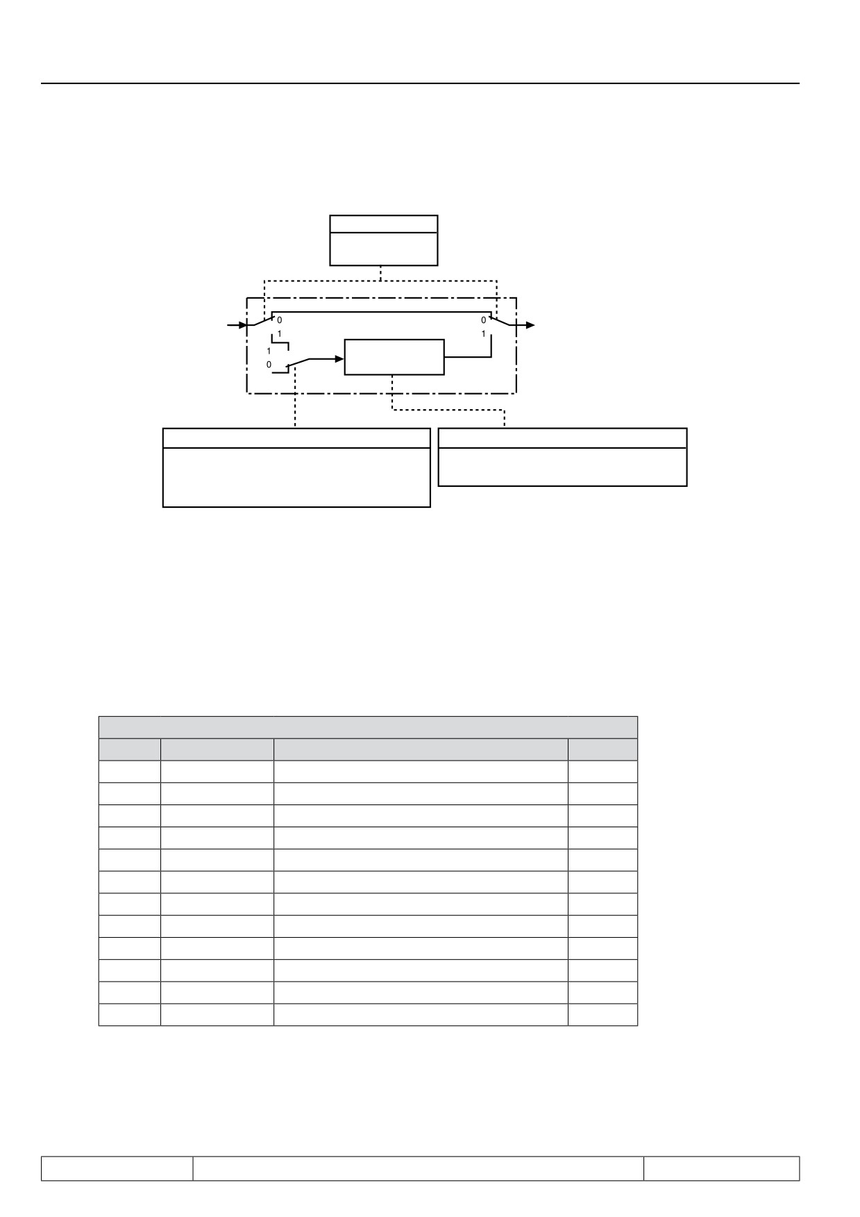
Figure 7.2.4 Save mode
An.02/12/22 Bit 0
0: Direct mode
1: Memory mode
From the
To the
input filter
characteristic amplifier
non-volatile
memory
Input selection An.03/ 13/ 23
An.02/ 12/ 22 Bit 1
Input inactive: Value not stored
1: delete (at switch-off)
Input active: Value stored
0: not delete (at switch-off)
7.2.4.1Input selection (An.03, An.13, An.23)
With An.03 / An.13 / An.23 thedigital inputs for storing are selected according to the table on the next page (also
see chapter 7.3.11 „Assignment of inputs“). In order to save an analog value, the save mode (An.02 / 12 / 22 =
1) must be switched on under An.02 / 12 / 22 and the selected input must be activated.
An.03, An.13, An.23: Input selection
Bit
Decimal value
Input
Terminal
0
1
ST (prog. input „control release/reset“)
X2A.16
1
2
RST (prog. input „reset“)
X2A.17
2
4
F (prog. input „forward“)
X2A.14
3
8
R (prog. input „reverse“)
X2A.15
4
16
I1 (prog. input 1)
X2A.10
5
32
I2 prog. input 2)
X2A.11
6
64
I3 (prog. input 3)
X2A.12
7
128
I4 (prog. input 4)
X2A.13
8
256
IA (internal input A)
no
9
512
IB (internal input B)
no
10
1024
IC (internal input C)
no
11
2048
ID (internal input D)
no
Page7.2 - 6
Analog In- and Outputs I
7.2.5
Zero clamp (An.04, An.14, An.24)
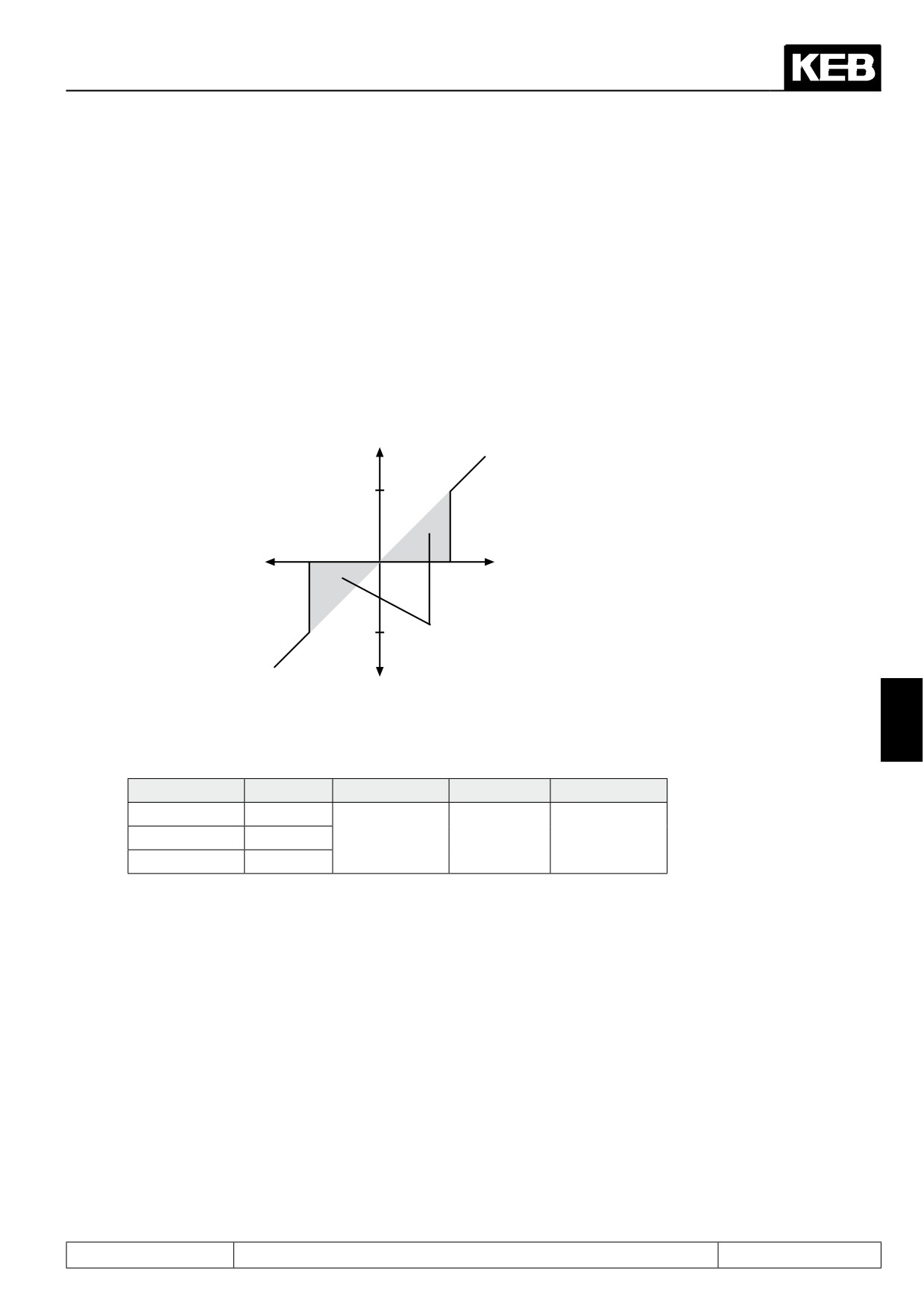
Through capacitive as well as inductive coupling on the input lines or voltage fluctuations of the signal source,
the motor connected to the inverter can still drift (tremble) during standstill in spite of the analog input filter. It is
the task of the zero clamp to suppress this.
With the parameters An.04 / 14 / 24 the respective analog signals can be faded out within a range of 0...±10%.
The adjusted value is valid for positive and negative input signals.
If a negative percent value is adjusted the hysteresis acts in addition to the zero point around the current set-
point. Setpoint changes are accepted only if they are larger than the adjusted hysteresis.
Fig. 7.2.5
Zero clamp
Output signal (for the further signal processing)
10%
Input signal co-
-10%
ming from noise
10%
filter
-10%
fade-out range
7
Value range
Input
Parameter
Value range
Resolution
Default value
AN1
An.04
AN2
An.14
0...±10 %
0,1%
0,2%
AN3
An.24
Page7.2 - 7
Analog In- and Outputs I
7.2.6
Gain of the input characteristics (An.05...07, An.15...17, An.25...27)
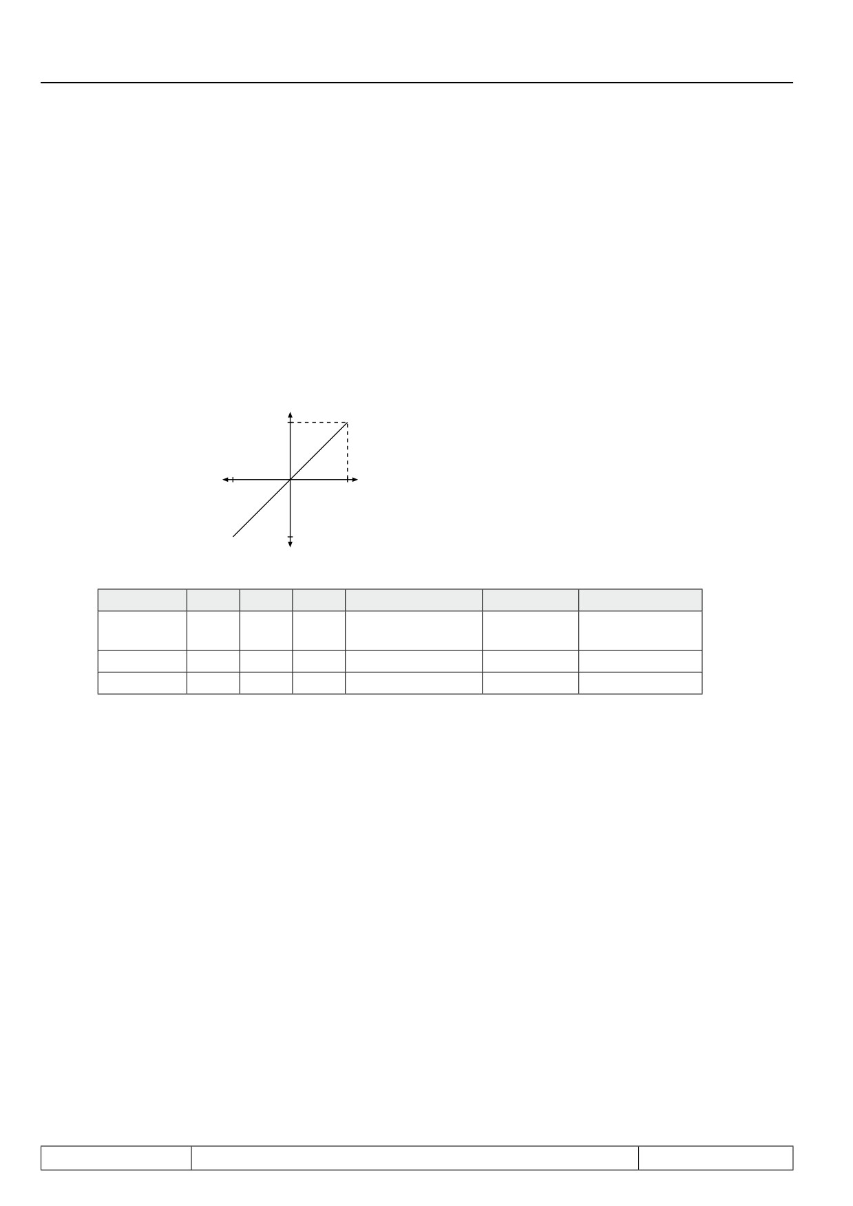
With these parameters the input signals can be adapted in X and Y direction as well as in the rise to the requi-
rements. In the case of factory setting no zero point offset is adjusted, the rise (gain) is 1, i.e. the input value
corresponds to the output value of this step (see Fig. 7.2.6.a). The output value is calculated according to
following formula:
Out = Amplification • ( In - Offset X) + Offset Y
Fig. 7.2.6.a
Default: no Offset, Gain 1
Output value (Out)
100%
Input value (In)
-100%
100%
-100%
Input
AN1
AN2
AN3
Value range
Resolution
Default value
Amplifica-
An.05
An.15
An.25
-20,00...20,00
0,01
1,00
tion
Offset X
An.06
An.16
An.26
-100,0%...100,0%
0,1%
0,0%
Offset Y
An.07
An.17
An.27
-100,0%...100,0%
0,1%
0,0%
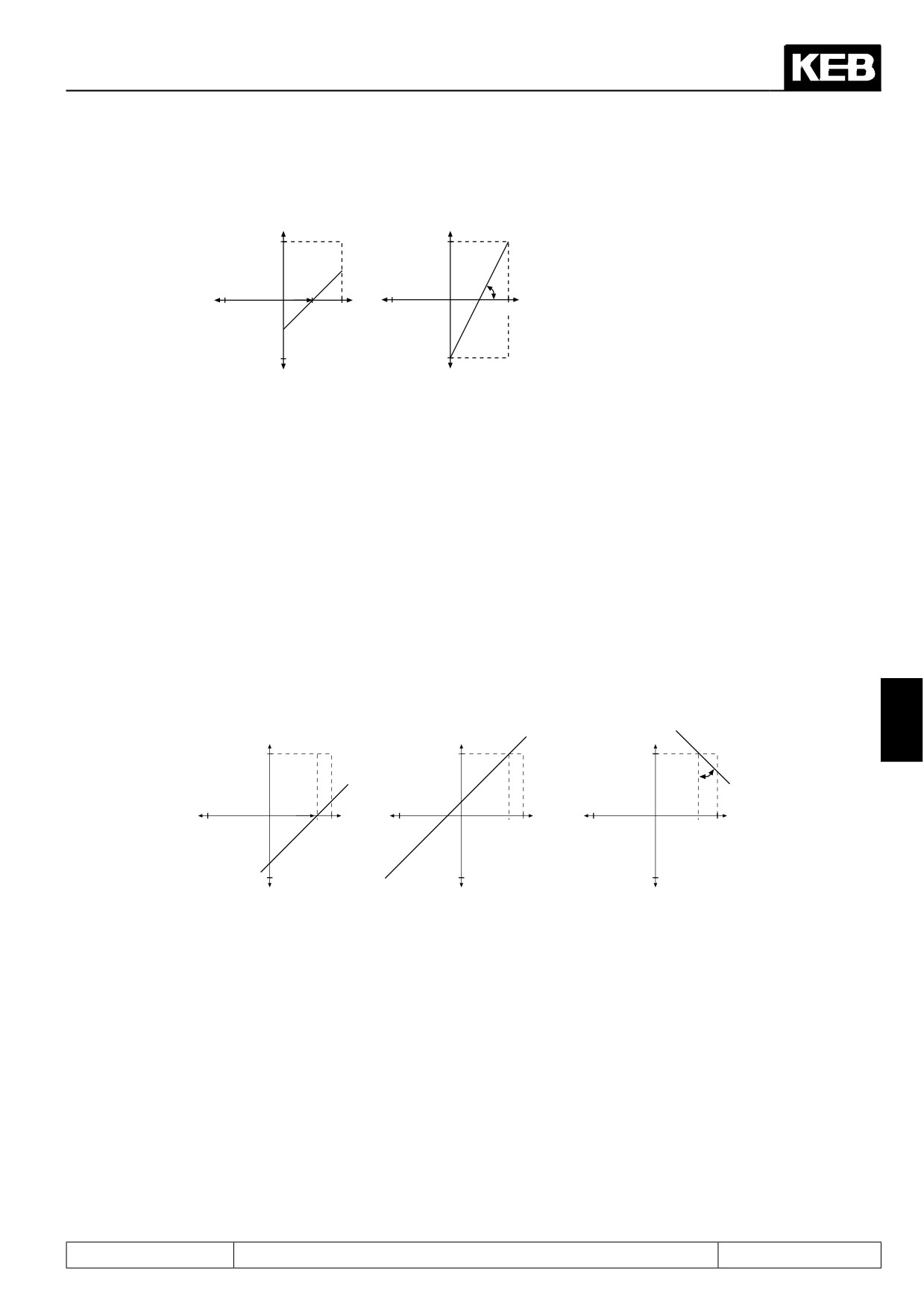
By means of some examples, we want to show the possibilities of the function. According to Fig. 7.2.6.b
1. Adjustment of the X-Offset for input AN1 to 50 (%)
2. Adjustment of the amplification to 2
Page7.2 - 8
Analog In- and Outputs I
Figure 7.2.6.b X-Offset (An.06) =50%; amplification (An.5)=2.00
1.
100%
2.
100%
An.5
An.6
-100%
50%
100%
-100%
100%
-100%
-100%
With these settings the entire speed range can be driven with 0...10 V via input AN1. (rotation direction = ±ana-
log)
0% In
corresponds
-100% Out
50% In
corresponds
0% Out
100% In
corresponds
100% Out
According to Fig. 7.2.6.c
1. Adjustment of the X-Offset for the input AN1 to 75 (%)
2. Adjustment of the Y-Offset for the input AN1 to 100 (%)
3. Adjustment of the amplification to -1
Fig.7.2.6.c X-Offset (An.06)=75%; Y-Offset (An.07)= 100%; amplification. (An.5)= -1.00
7
An.7=100%
An.7=100%
100%
An.5
An.6=75%
-100%
100%
-100%
100%
-100%
100%
-100%
-100%
-100%
Page7.2 - 9
Analog In- and Outputs I
7.2.7
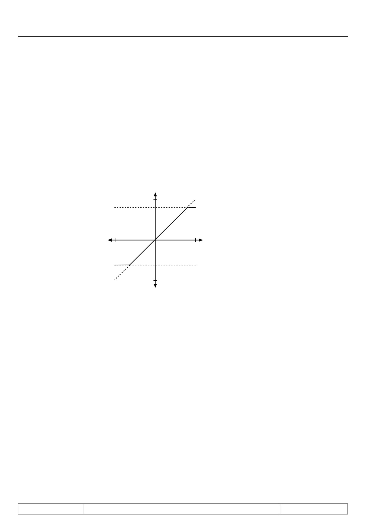
Lower and upper limit (An.08, An.09, An.18, An.19, An.28, An.29)
These parameters serve for the limiting of the analog signals after the amplifier stage.All parameters are ad-
justable in the range of -400...400 %. Since no mutual locking exists, it is to be ensured, that the lower limit is
adjusted smaller than the upper limit.
An.08 AN1 lower limit
An.09 AN1 upper limit
An.18
AN2 lower limit
An.19
AN2 upper limit
An.28
AN3 lower limit
An.29
AN3 upper limit
Fig. 7.2.7 Limiting of the analog signal
400%
An.9 / An.19 / An.29
-400%
400%
An.8 / An.18 / An.28
-400%
Page7.2 - 10
Analog In- and Outputs I
7.2.8
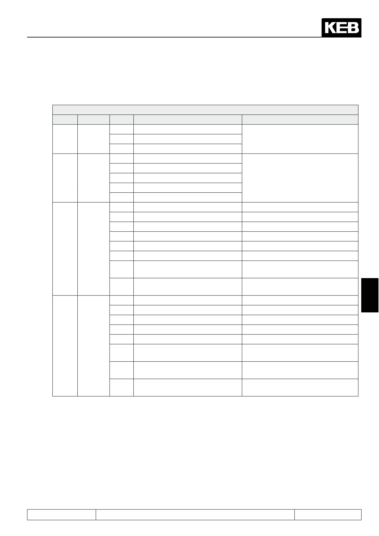
Selection REF input / AUX-function (An.30)
Assignment of the analog inputs:
An.30 Selection REF input / AUX function
Bit
Function
Value
Description:
Explanation
0
AN1 input (ru.28)
Selection
Selection of the analog channel, which
0...2
REF
1
AN2 input (ru.30)
serves as REF input
Input
2
AN3 input (ru.32)
0
Aux = source 1
8
Aux = source 1 + source 2
Selection of the AUX input value calcu-
AUX
3...5
16
Aux = source 1 x (100% + source 2)
lation (addition, multiplication or absolu-
mode
te-value generation)
24
Aux = source 1 x source 2
32
Aux = source 1 absolute
0
AN1 input (ru.28)
Source 1 = AN1 after amplification
64
AN2 input (ru.30)
Source 1 = AN2 after amplification
128
digital % (op.05)
Source 1 = value of oP.05
192
Motorpoti (ru.37)
Source 1 = motorpoti value
Aux 1
256
Ext. PID output display (ru.52)
Source 1 = PID controller base value
6...10
source
320
AN3 input (ru.32)
Source 1 = AN 3 after amplification
384
Encoder value channel 1 (ru.04 / 09)
Source 1 = ru.09 / reference value x
100%
448
Encoder value channel 2 (ru.05 / 10)
Source 1 = ru.10 / reference value x
100%
7
0
AN1 input (ru.28)
Source 2 = AN1 after amplification
2048
AN2 input (ru30)
Source 2 = AN2 after amplification
4096
digital % (op.05)
Source 2 = value of oP.05
6144
Motorpoti (ru.37)
Source 2 = motorpoti value
8192
Ext. PID output display (ru.52)
Source 2 = PID controller base value
Aux 2
11...15
source
10240
AN3 (ru.32)
Source 2 = AN 3 after amplification
12288
Encoder value channel 1 (ru.04 / 09)
Source 2 = ru.09 / reference value x
100%
14336
Encoder value channel 2 (ru.05 / 10)
Source 2 = ru.10 / reference value x
100%
The reference value for the calculation of the AUX signal of the encoder values of channel 1 or 2 is dependent
on ud.02:
-
Reference value = 1000 rpm in the mode 4000 (ud.02 = 4 or 10)
-
Reference value = 2000 rpm in the mode 8000 (ud.02 = 5 or 11)
-
etc. (see chapter 5.1, reference values dependent on the speed range)
Page7.2 - 11
Analog In- and Outputs I
7.2.9
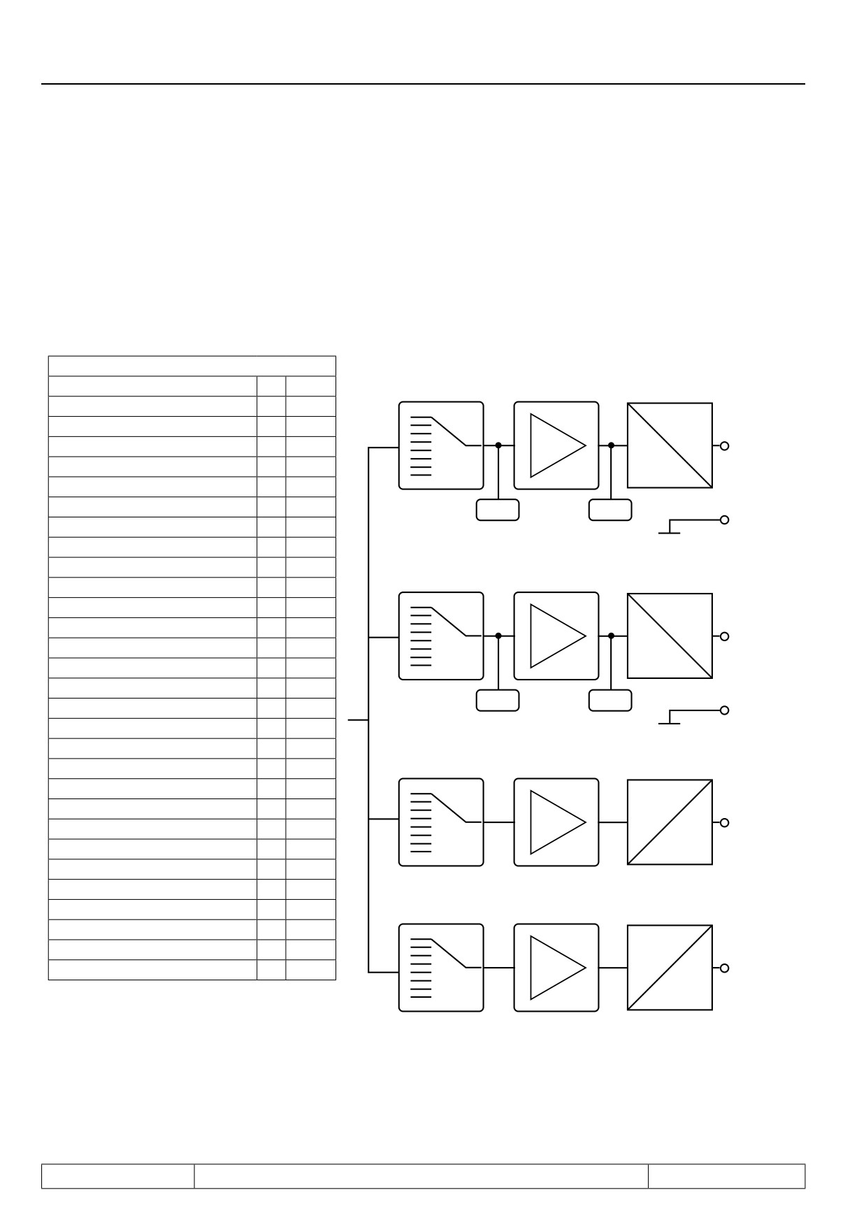
Brief description analog outputs
The KEB COMBIVERT has three programmable outputs (ANOUT1, 2 and ANOUT3, 4). Parameters An.31/36
allow the selection of one size which is given out at the outputs X2A.5 / 6. ANOUT 3 and ANOUT 4 (An.41 / 47)
may be output as switching condition 42, or 43 with the digital outputsas PWM signal. The analog signals can
be adapted to the requirements with the characteristic amplifier (An.33...35 / An.38...40 / 43...45/ 49...51).The
ru-parameters show the current size before and after the amplification. The period time for the PWM-signal can
be adjusted with An.46 / 52.
Figure 7.2.9 Principle of the analog inputs
An.31/36/41/47
An.33
An.34
Absolute actual value
0
ru.7
An.31
An.35
Absolute reference
1
ru.1
0...±10V
Actual value
2
± ru.7
X2A.5
Setpoint value
3
± ru.1
ANOUT1
Output voltage
4
ru.20
0...±100%
DC-link voltage
5
ru.18
Apparent current
6
ru.15
ru.33
ru.34
X2A.8
AGND
Active current
7
ru.17
Digital setting via An.32/37/42/48
8
An.xx
An.38
External PID output
9
± ru.52
An.39
An.36
An.40
Absolute ext. PID output
10
ru.52
Absoluter active current
11
ru.17
0...±10V
Power stage temperature
12
ru.38
X2A.6
ANOUT2
Motor temperature
13
ru.46
Actual torque
14
± ru.12
0...±100%
Absolute actual torque
15
ru.12
ru.35
ru.36
X2A.9
Set torque
16
± ru.11
AGND
Absolute set torque
17
ru.11
An.43
Control difference / speed control
18
-
An.44
Speed reference variable
19
± ru.2
An.45
An.41
An.46
Abs. speed reference variable
20
ru. 2
100%
Angular deviation
21
ru.58
do.0...do.7
AN1 before amplification
22
ru.27
Wert “42”
AN1 after amplification
23
ru.28
PWM
AN2 before amplification
24
ru.29
AN2 after amplification
25
ru.30
An.49
An.50
Active power
26
ru.81
An.47
An.51
An.52
Actual position
27
ru.54
100%
Set position
28
ru.56
do.0...do.7
Max. torque in %
29
ru.90
Wert “43”
PWM
The reference values formode 0-3 and 18-20 change dependent on ud.02.
Page7.2 - 12
Analog In- and Outputs I
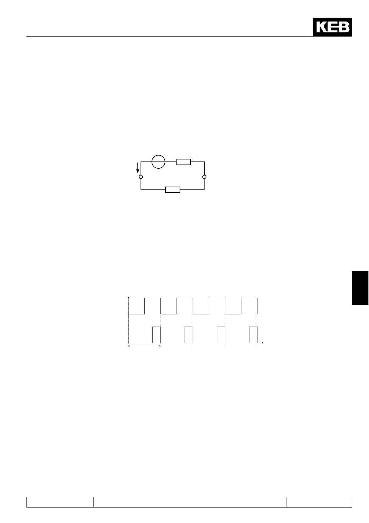
7.2.10Output signals
ANOUT 1 / 2, bipolar
A voltage of 0...±11,5 VDC represents the selected size in the range of 0...±115 % with a resolution of
10 Bit
at the output. In order to be able to balance load-dependent voltage drops, the limitation at the output of the
characteristic amplifiers is
±115 %.
Fig. 7.2.10 Analog output
Uout = 0...±11,5 V
+
-
Imax = 5mA
R
i < 100Ω
AGND
ANOUT1 (X2A.5) /
(X2A.8 / X2A.9)
ANOUT2 (X2A.6)
RB
ANOUT 3 / 4, PWM output
Process variables, that change only slowly, as for example the power module temperature, can be output over
two virtual analog outputs (ANOUT3 and 4). This is realised through generation of a PWM-signal (pulse-width-
modulation) on a digital output. Period T can be adjusted with parameter An.46 or An.52 „ANOUT period“ of
1...240 s.
Fig. 7.2.10.a PWM output signal
ANOUT 3/4
7
Input value 50 %
Input value 25 %
t
T= An.46/52
7.2.11 Analog output / display (ru.33...34 / ru.35...36)
Following parameters are used for the indication of the analog outputs, before and after the characteristic am-
plification:
ru.33 ANOUT1 / pre amplification display
0...±400 %
ru.34 ANOUT1 / post amplification display
0...±115 %
ru.35 ANOUT2 / pre amplification display
0...±400 %
ru.36 ANOUT2 / post amplification display
0...±115 %
At the outputs ANOUT3 and 4 there is no display provided.
Page7.2 - 13
Analog In- and Outputs I
7.2.12ANOUT 1/ -2/-3/-4/ function (An.31 / An.36 / An.41, An.47)
These parameters define the function which controls the respective output. Following adjustments are possi-
ble:
An.31/ An.36/ An.41/ An.47
Va-
Function
Output of
100 % corresponds
lue
0
Absolute actual value ru.07
Amount of the actual speed value
Amount of the speed set value before
1
Absolute set value ru.01
ramp generator
3000 rpm 2)
2
Actual value ru.07
Actual speed value
3
Set value ru.01
Speed setpoint
4
Output voltage ru.20
Output voltage
0...500 V
5
DC voltage ru.18
DC-link voltage
0...1000 V
6
Apparent current ru.15
Apparent current
0...2 x inverter rated current
7
Active current ru.17
Active current
(In.01)
8
Digital setting by An.32/ 37/ 42/ 48
by An.32/ 37/ 42/ 48 preset value
9
External PID output ru.52
Base value of the PID controller
0...100 %
Amount of the PID controller base va-
10
Absolute ext. PID output ru.52
lue
0...2 x inverter rated current
11
Absolute active current ru.17
Amount of the active current
(In.01)
12
Heat sink temperature ru.38
Power module temperature
0...100 °C
13
Motor temperature ru.46
Motor temperature
14
Actual torque (F5-M/S)
Actual torque
0...3 x rated torque
15
Absolute actual torque (F5-M/S)
Amount actual torque
only for closed
DASM: dr.14
16
Set torque (F5-M/S)
Set torque
-loop control
DSM: dr.27
17
Absolute set torque (F5-M/S)
Amount set torque
operation
System deviation of the speed control-
System deviation of the speed control-
18
ler
ler
19
Speed reference variable ru.02
Speed set value after ramp generator
0...3000 rpm 2)
Absolute speed reference variable
20
Angular deviation
ru.02
0... Display increments for a
21
Angle difference (ru.58)
Angular deviation
revolution
Analog input
1 before amplification
22
Value of AN.01 at the terminal
(ru.27)
Analog input
1 after amplification
Value of AN.01 after analog value pro-
23
(ru.28)
cessing
0...100 %
Analog input
2 before amplification
24
Value of AN.02 at the terminal
(ru.29)
Analog input
2 after amplification
Value of AN.02 after analog value pro-
25
(ru.30)
cessing
0...2 x rated motor power
26
Active power (ru.81)
Active power
DASM: dr.03
DSM: dr.32
Page7.2 - 14
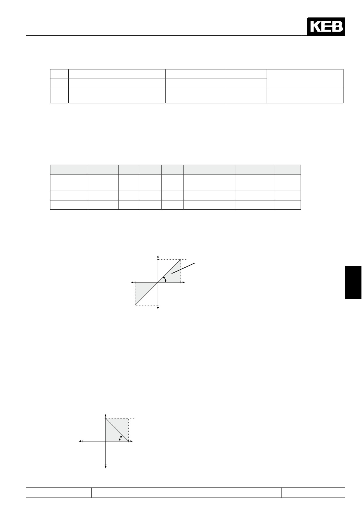
Analog In- and Outputs I
27
Actual position (ru.54)
Actual position
Ref. position 0 % (PS.41)
28
Set position (ru.56)
Set position
Ref. position 100 % (PS.42)
actual torque, referring to the max. per-
29
Max. torque in % (ru.90)
0...100 %
missible torque of the drive chain
1) dependent on inverter rated current (In.1),
2) dependent on ud.2, 3) dependent on the motor
7.2.13Gain of Output Characteristic (An.33...35 / An.38...40 / An.43...45 / An.49...51)
The characteristic amplifier are following after selecting the signal to be given out (see fig. 7.2.9). With these
parameters the input signals can be adapted in X and Y direction as well as in the rise to the requirements. With
factory setting no zero point offset is adjusted, the gain is 1, i.e. 100% of the variable to be given out correspond
to 10V at the analog output (see fig. 7.2.14.a).
Function
ANOUT1
-2
-3
-4
Value range
Resolution
Default
Amplifica-
An.33
An.38
An.43
An.49
±20,00
0,01
1,00
tion
X offset
An.34
An.39
An.44
An.50
±100,0%
0,1%
0,0%
Y offset
An.35
An.40
An.45
An.51
±100,0%
0,1%
0,0%
Fig. 7.2.13.a Factory setting: no Offset, Gain 1
Output voltage
100%
10V
Displayable
range
Variable to be indica-
An.33
-100%
An.34
ted
7
100%
-100%
An.35
Inverting the analog output
An example for using the characteristic amplifier is shown in Fig. 7.2.14.b:
1. Adjustment of the X-Offset (An.34) to 100 (%)
2. Adjustment of the amplification (An.33) to -1.00
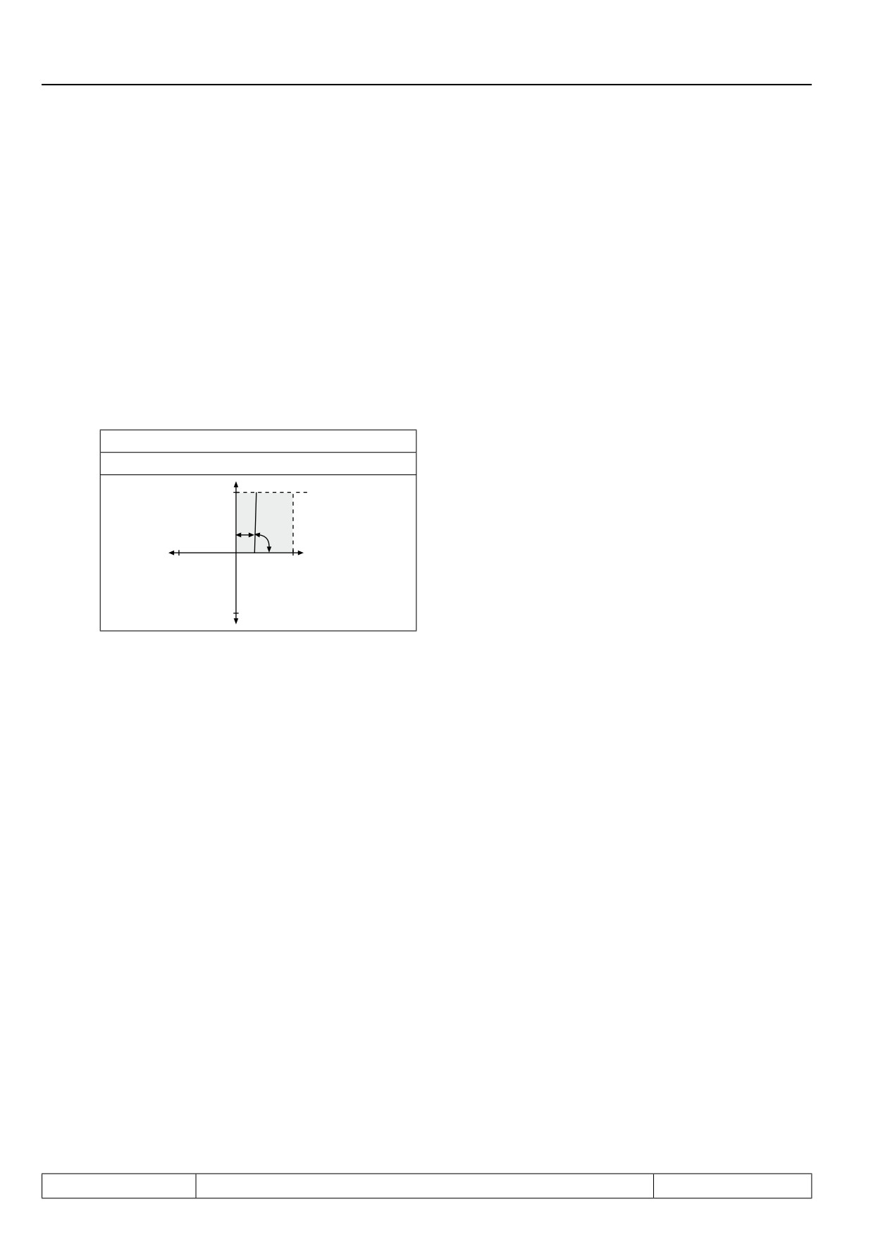
Figure 7.2.13.b Inverse of the analog output
An.35
100%
10V
An.33
An.34
-100%
100%
-100%
Page7.2 - 15
Analog In- and Outputs I
These settings result in an inverting of the analog signal.
0%
corresponds to 10V
at the output
100%
corresponds to 0 V
at the output
Analog output as switch
An example for using the analog output as 0/10V-switch is shown in fig. 7.2.13.c:
1. Adjustment of the amplification (An.33) to 20.00
2. Adjustment of the X-Offset (An.34) to the desired switching level
Figure 7.2.13.c Analog output as a switch
100%
10V
An.34
An.33
-100%
100%
-100%
Because of the high amplification the analog output switches in a relative small switching window.
Computation of the amplification
Since the analog output always works firmly onto the values defined under 7.2.12, one can adjust the characte-
ristic with the aid of the amplification so that the complete range
0...±10V is utilized.
defined value
---------------
= amplification (An.33/ 38/ 43/ 49)
desired value
Example Output frequency (it is not valid for F5-M):
100Hz
-----
= 1.47
68Hz
7.2.14ANOUT 1...4 digitale setting (An.32 / 37 / 42 / 48)
Analog values can be preset in percent for the respective input with parameters An.32/ An.37/ An.42/ An.48. For
that purpose the value8: „digital setting“ must be adjusted. The setting is done within the range ±100 %.
Page7.2 - 16
Digital In- and Outputs
7.1
Operating and appliance data
1.
Introduction
7.2
Analog in- and outputs I
2.
Summary
7.3
Digital in- and outputs
3.
Hardware
7.4
Setpoint-, rotation- and ramp adjustment
Motor data and controller adjustments of the asynchronous
7.5
4.
Operation
motor
Motor data and controller adjustments of the synchronous
7.6
motor
Selection of Operating
5.
Mode
7.7
Speed control
6.
Initial Start-up
7.8
Torque display and -limiting
7.9
Torque control
7.
Functions
7
7.10
Current control, -limiting and switching frequencies
8.
Error Assistance
7.11
Speed measurement
9.
Project Design
7.12
Positioning and synchronous control
7.13
Protective functions
10. Networks
7.14
Parameter sets
11. Parameter Overview
7.15
Special functions
12. Annex
7.16
CP-Parameter definition
Page7.3 - 1
Digital In- and Outputs
7.3.1
Summary description digital inputs
7.3 - 3
7.3.2
Input signals PNP / NPN selection (di.00)
7.3 - 4
7.3.3
Setting of digital inputs by software (di.01, di.02)
7.3 - 5
7.3.4
Input terminal state (ru.21), internal input state (ru.22)
7.3 - 6
7.3.5
Digital noise filter (di.03), fast dig. noise filter (di.23)
7.3 - 6
7.3.6
Input logic (di.04)
7.3 - 6
7.3.7
Input trigger (di.05)
7.3 - 6
7.3.8
Strobe-dependent inputs (di.06, di.07, di.08)
7.3 - 7
7.3.10
Error reset / input selection and edge evaluation (di.09 / di.10)
7.3 - 8
7.3.11
Assignment of the inputs
7.3 - 9
7.3.12
Software ST and locking of the control release
7.3 - 12
7.3.13
Deactivation of the digital control release
7.3 - 12
7.3.14
Summary description digital outputs
7.3 - 13
7.3.15
Output signals / hardware
7.3 - 14
7.3.16
Output filter (do.43, do.44)
7.3 - 14
7.3.17
Switching conditions (do.00...do.07)
7.3 - 15
7.3.18
Inverting of switching conditions for flags 0...7 (do.08...do.15)
7.3 - 20
7.3.19
Selection of switching conditions for flags 0...7 (do.16...do.23)
7.3 - 20
7.3.20
Linking the switching conditions for flags (do.24)
7.3 - 20
7.3.21
Inverting of flags (do.25...do.32)
7.3 - 21
7.3.22
Selection of flags (do.33...do.40)
7.3 - 21
7.3.23
Linking the flags(do.41)
7.3 - 22
7.3.24
Output terminal state (ru.25) and digital output state (ru.80)
7.3 - 23
7.3.25
Hardware output allocation (do.51)
7.3 - 23
7.3.26
Programming example
7.3 - 24
Page7.3 - 2
Digital In- and Outputs
7.3
Digital in- and outputs
7.3.1
Summary description digital inputs
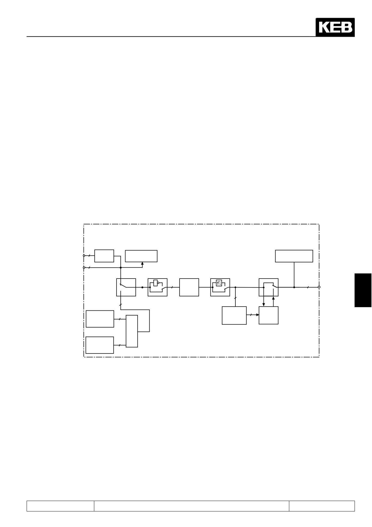
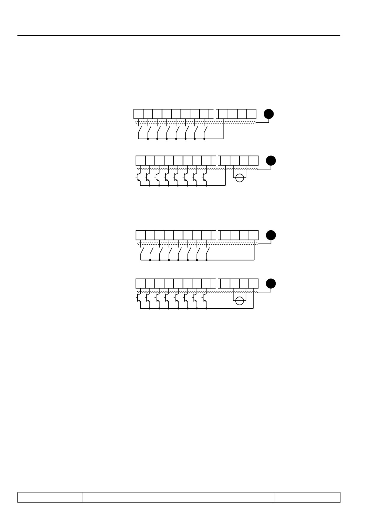
The KEB COMBIVERT has 8 external digital inputs and 4 internal inputs (IA...ID). All inputs can be assigned
to one or several functions.
Coming from the terminal strip it can be defined with parameter di.00, whether external inputs shall be con-
trolled in PNP or NPN (not at safety relais) wiring. Parameter ru.21 shows the currently controlled input. Each
input can optionally (di.01) be set via terminal strip or by means of software with di.02. A digital filter (di. 03,
di.23) reduces the interference susceptibility of the inputs. The inputs can be inverted with di.04 and with di.05
one can switch to edge-triggering. With the parameters di. 06...di. 08 a Strobe-mode can be activated. The
input status (ru.22) shows the inputs that are actually set for processing. The function(s), that a programmed
input carries out, is defined by means of the input selection of the corresponding function or by di.11...22.
For safety reasons the control release (ST) must generally be switched by means of hardware. Edge-trigge-
ring, inversion and strobe signal can be adjusted but have no influence.
Figure 7.3.1 Principle of the digital inputs
Terminal
DI
RU
RU
strip
PNP/
Terminal
2A.10...17
Input state
NPN
state
Internal
inputs
IA...ID
DI
DI
DI
DI
DI
Digital
filter
Assign-
7
ment of
the inputs
DI
Define
digital
strobe
Strobe
input
mode
input
setting
DI
DI
r
3Y
Control
word long
Page7.3 - 3
Digital In- and Outputs
7.3.2
Input signals PNP / NPN selection (di.00)
Figure 7.3.2.a Digital inputs in PNP control (di.00 = 0)
24V
24V
I1
I2
I3
I4
F R STRST
GND
out
in
Internal supply
X2A
10
11
12
13
14
15
16
17
20
21
22
23
PE
Ri (digital input) = 2,1
24V
24V
kΩ
I1
I2
I3
I4
F R ST RST
GND
out
in
X2A
10
11
12
13
14
15
16
17
20
21
22
23
PE
External supply
+
Switching voltage for digital inputs = 13...30V DC ±0% smoothed
Figure 7.3.2.b Digital inputs in NPN control (di.00 = 1)
24V
24V
I1
I2
I3
I4
F R
ST RST
GND
out
in
Internal supply
X2A
10
11
12
13
14
15
16
17
20
21
22
23
PE
Ri (digital input) = 2,1kΩ
External supply
Page7.3 - 4
Digital In- and Outputs
7.3.3
Setting of digital inputs by software (di.01, di.02)
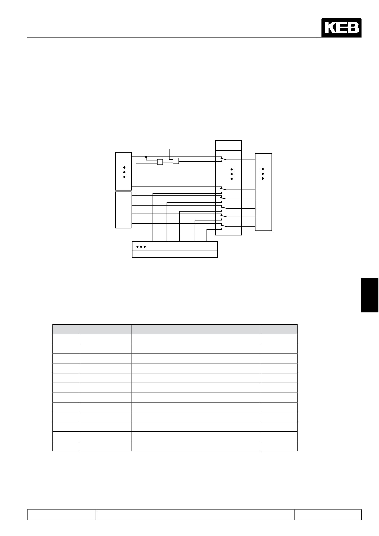
With the aid of parameter di.01 and di.02 the digital input can be set without external wiring.
The control release must generally be switched by means of hardware even if one switches by software (see
Fig. 7.3.3 AND-operation with di.02 and sy.50)!
Figure 7.3.3 Digital inputs controlled by software (di.01/di.02)
Sy.50 Bit0 = 1
di.1
ST
1
ST
Terminal strip
&
&
I4
128
I4
IA
256
Internal inputs
IA
IB
512
IB
IC
1024
IC
ID
2048
ID
1
128 256 512 1024 2048
di.2
As shown in Fig. 7.3.3, it can be selected with di.01, whether the inputs shall be switched from the terminal
strip (default) or by way of parameter di.02. Both parameters are bit-coded, i.e. according to following table, the
appropriate value for the input is to be entered. In the case of several inputs the sum is to be formed.
(Exception: Control release must always be bridged at the terminal strip).
7
Table terminal status
Bit No.
Decimal value
Input
Terminal
0
1
ST (prog. input "control release/reset")
X2A.16
1
2
RST (prog. input "reset")
X2A.17
2
4
F (prog. input "forward")
X2A.14
3
8
R (prog. input "reverse")
X2A.15
4
16
I1 (prog. input 1)
X2A.10
5
32
I2 (prog. input 2)
X2A.11
6
64
I3 (prog. input 3)
X2A.12
7
128
I4 (prog. input 4)
X2A.13
8
256
IA (internal input A)
no
9
512
IB (internal input B)
no
10
1024
IC (internal input C)
no
11
2048
ID (internal input D)
no
Example: ST, F and IB are controlled, indicated value = 1+4+512 = 517
Page7.3 - 5
Digital In- and Outputs
7.3.4
Input terminal state (ru.21), internal input state (ru.22)
The input terminal state (ru.21) displays the logical level of the input terminals. It is unimportant, whether the
inputs are internally active or not. If a terminal is controlled, then the appropriate decimal value according to the
table below is output. If several terminals are active, then the sum of the decimal values is output.
The internal input state (ru.22) shows the logic condition of the digital inputs which are internally set for pro-
cessing. If an input is set, the appropriate decimal value according to the table under 7.3.1 is output. If several
inputs are set, then the sum of the decimal values is output.
7.3.5
Digital noise filter (di.03), fast dig. noise filter (di.23)
The digital filter reduces the susceptibility to interferences on the digital inputs. Only hardware inputs can be
filtered. Each input port has a separate filter counter, counting upward for active ports and downward for inac-
tive ports. The output of the filter is set when the filter time is reached and is reset at zero.
Parameter
Setting range
Resolution
di. 03
0...127 ms
1 ms
di. 23
0...31,75 ms
0,25 ms
Priority of filter times: The greater of the two times is used.
7.3.6
Input logic (di.04)
With parameter di.04 it can be adjusted, whether a signal is 1- or 0-active (inverted). The parameter is bit-
coded, i.e. the value belonging to this input must be entered. If several inputs shall be inverted, then the sum is
to be formed. (Exception: An inversion of the control release remains without function.)
7.3.7
Input trigger (di.05)
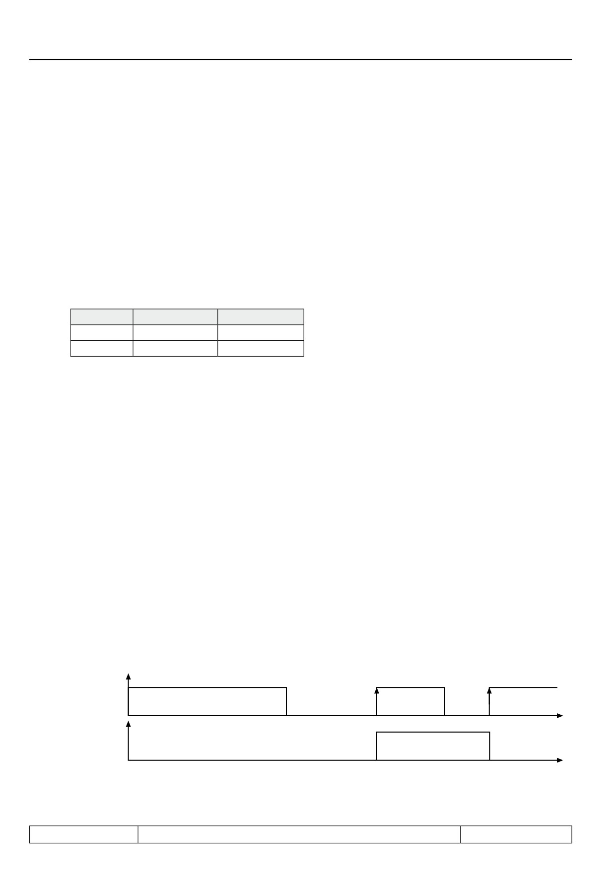
As a standard the inverter is controlled with static signals, i.e. an input is set for as long as a signal is applied.
However, practice has shown that a signal may be available for a limited time only, but the input shall still remain
set. In that case the input or several inputs can be adjusted to edge-triggered flip-flop. Then a rising edge with
a pulse duration that is longer than the response time of the digital filter is sufficient for switch-on. Switch-off is
effected with the next rising edge.
Control release (ST) can be set to edge-triggered flip-flop, but remains without affect on the function, since it is
a pure static signal.
Figure 7.3.7 Example of a signal flow diagram for input I1 (di.05=16)
Input signal after
filtering
t
Input trigger
t
Page7.3 - 6
Digital In- and Outputs
7.3.8
Strobe-dependent inputs (di.06, di.07, di.08)
A Strobe signal is used mainly for triggering the input signals. For example, two inputs shall be used for the
parameter set selection. But the signals for the control do not arrive exactly even, so for a short time it would
be switched into an unintended set. With active strobe (scanning signal) the current input signals of the strobe-
dependent inputs are accepted and kept until the next scanning.
Which inputs are switched by strobe?
With di.08 any input can be selected as strobe-dependent input. With the control release di.08 has no function
since this is a static input.
From where comes the strobe signal?
With parameter di.06 the strobe input is set. If several inputs are adjusted as strobe they are linked in OR-
operation.
Edge-active or static strobe?
As a standard the strobe is edge-active, i.e. the input conditions on the strobe input are accepted with rising
edge and maintained until the next increase edge. For some applications it is sensible to use the strobe in a
manner of a gate function. In that case the strobe signal is static, i.e. the input signals are accepted for as long
as the strobe signal is set (or for as long as the gate is open).
di.07 Strobe mode
di.07: Strobe mode
Value
Function
Description
7
Input states are stored at the rising edge of the strobe input and are
0
Edge-active strobe (default)
held until the next rising edge.
Static strobe - froze if strobe
Input states are updated as long as the strobe signal is set. When
1
is not active
the signal becomes inactive, the state is held.
Static strobe - only active at
Input states are updated as long as the strobe signal is set. When
2
active strobe
the signal becomes inactive, the state is reset.
Page7.3 - 7
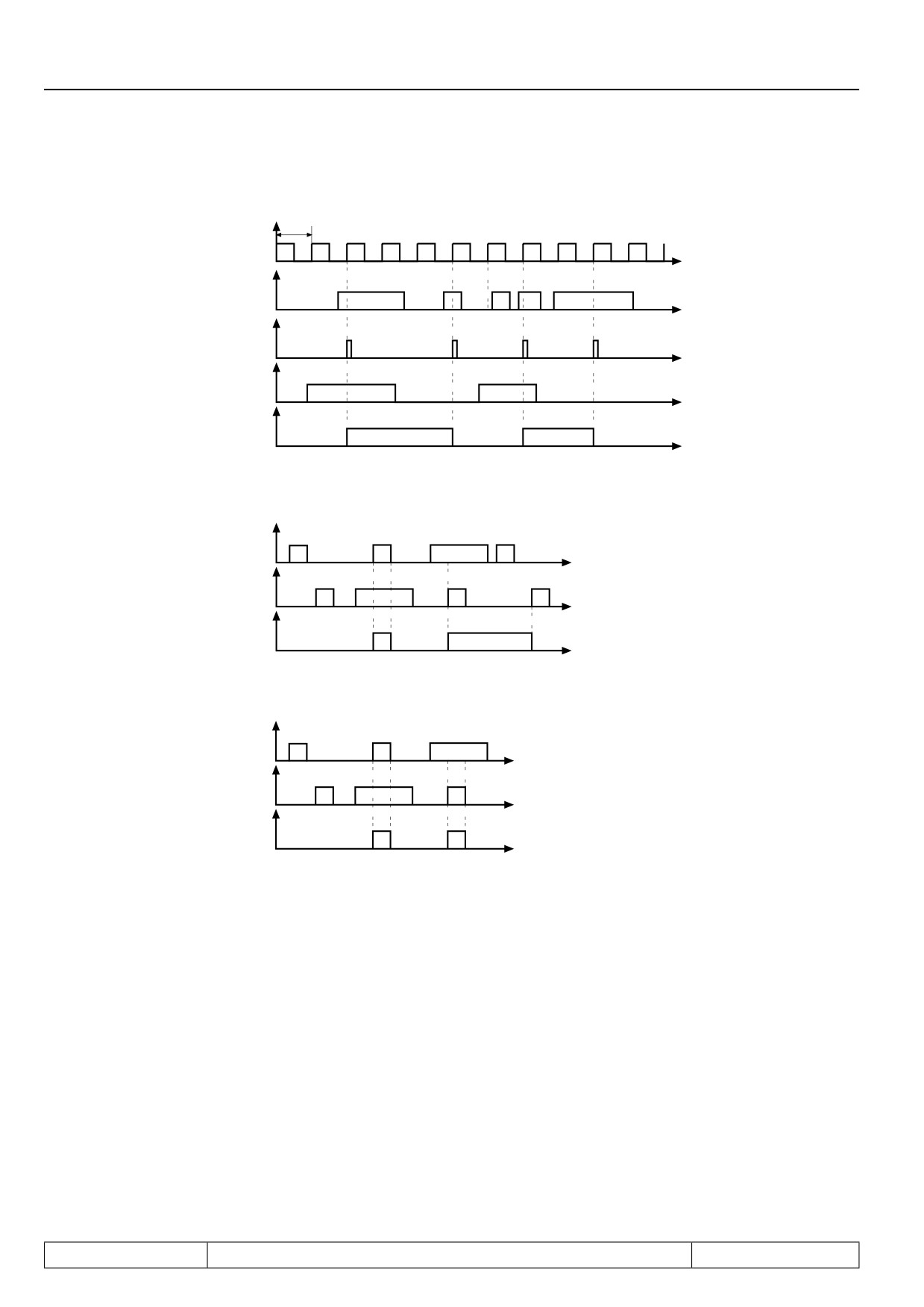
Digital In- and Outputs
Figure 7.3.8.a Edge active strobe (di.07 = 0)
scanning grid (accep-
1ms
tance upon rising edge)
t
Strobe input
t
Resulting
Strobe signal
t
Signal on
Terminals
t
Input status
t
Figure 7.3.8.b Static strobe mode 1 (di.07 = 1)
Input signal
t
Strobe signal
t
Input status
t
Figure 6.3.8.c Static strobe mode 2 (di.07 = 2)
Input signal
t
Strobe signal
t
Input status
t
7.3.10Error reset / input selection and edge evaluation (di.09 / di.10)
With di.09 the reset input is defined according to the table under 7.3.1. If the reset input shall react to an edge,
one or several of the reset inputs defined with di.09 can be switched to edge evaluation with di.10.
Page7.3 - 8
Digital In- and Outputs
7.3.11 Assignment of the inputs
There are two strictly different procedures for the assignment of inputs.
a.) Each function can be associated with one or more inputs. I.e., for each function (positioning, constant
selection, etc.) an input can be selected that activates this function.
b.) Each digital input can be associated with one or more functions. I.e.,each digital input can be associated
with one or more functions for the parameters di.11...di.22 "function" and di.24...di.35 "+ function". For
the parameters di.11...di.22 each input can be associated with multiple functions, for the parameters
di.24...di.35 only one function can be selected.
Both variants mutually influence each other; i.e., if an input is associated with a function, the parameters di.11...
di.22 and di.24...di.35 are adjusted accordingly .
Because of the two variants, the control combines two advantages:
-
with the functional programming of the inputs, the function's parametrization also permits selecting
which inputs will activate the function,
-
with the input-oriented display one gets a complete overview of the functionality of an input and can
check whether there are any unwanted interactions between functions.
The following table shows a list of the parameters with which the various functions can be assigned digital
inputs:
An.03
AN1 save trigger input selection
oP.57
Motor poti decrease input selection
An.13
AN2 save trigger input selection
oP.58
Motor poti reset input selection
An.23
AN3 save trigger input selection
oP.60
Direction forward input selection
cn. 11
PID reset input selection
oP.61
Direction reverse input selection
7
cn. 12
I reset input selection
Pn.04
Ext. fault input selection
cn. 13
Fade in reset input selection
Pn.23
LAD stop input selection
di. 09
Reset input selection
Pn.29
DC brake input selection
di. 36
Software ST input selection
Pn.64
Set GTR7 input selection
di. 37
ST lock input selection
PS.02
Pos/syn input selection
di. 39
Disable dig. ST input selection
PS.03
Shift. slave input selection
dr.61
Rs corr. auto temp input selection
PS.10
Shift. slave inv. input selection
Ec.48
Scan channel 2 input selection
PS.18
Reference switch input selection
Ec.49
Scan channel 1+ 2 input selection
PS.19
Start reference input selection
Fr.07
Parameter set input selection
PS.29
Start posi input selection
Fr.11
Reset set input selection
PS.36
Teach input selection
LE.17
Timer 1 start input selection
PS.37
Pos. scan index input selection
LE.19
Timer 1 reset input selection
PS.38
Relative pos. f/r input selection
LE.22
Timer 2 start input selection
PS.43
Corr. reference point input selection
LE.24
Timer 2 reset input selection
uF.08
Energy saving input selection
oP.19
Step value input selection 1
uF.21
Dt.comp. off input selection
oP.20
Step value input selection 2
oP.56
Motor poti increase input selection
The following table shows an overview of all functions that can be assigned to a digital input with the parame-
ters di.11...di.22 (multiple functions can be used).
Page7.3 - 9