KEB COMBIVERT F5-A,-E,-H 4.0. APPLICATION MANUAL (2008) - page 4
Start-up
6.2.2
Start-up of a synchronous motor
The following chapter describes the initial start-up of a synchronous motor splitted in speed controlled systems
with encoder feedback (F5A-S) and speed controlled systems without encoder feedback (F5E-S).
6.2.2.1Start-up F5A-S
Steps 1 to 10 can be skiped when using a KEB servo system consisting of KEB COMBIVERT F5 and KEB
servo motor.
In this case the unit is already preset by a specific motor down load.
The following steps describe a standard start-up when using a "customer-specific motor“. Enocer interface 1 is
used as encoder feedback.
1.
Open control release
Deactivate terminal X2A.16
→ Inverter state ru.00 = noP/ „no control release“
2.
Selection of the speed range
The useable speed range is adjusted with ud.02:
All data for the adjustment of the controller
type (e.g. resolution of the speed, etc.) see
→ ud.02 control type = 8…11
chapter 5.1
3.
Loading the default parameters
Loading the default parameters (KEB factory setting) by Attention:
Preadjustments (e.g. function of the digital
→ Fr.01 copy parameter set = - 4
inputs) disappear
4.
Select source of the speed feedback
→ cS.01 actual source = 0: channel 1
5.
Enter increments per revolution of the speed feedback
→ Ec.01 encoder 1 (inc/r)
Note:
Not valid for resolver
Page6.2 - 16
Start-up
6.
Input of the motor rating plate data
→ dr.23 DSM rated current
Note: The approximation value of dr.23
→ dr.24 DSM rated speed
(rated current) can be used if dr.28 is not
→ dr.25 DSM rated frequency
indicated.
→ dr.27 DSM rated torque
Stator resistance and inductance must be
→ dr.28 DSM current for zero speed
preset as phase-phase values (RUV. LUV)
and the EMK must be preset as peak value
of the phase-phase voltage (√2 x UUV).
7.
Input of equivalent circuit data
The values can be taken from a data sheet
- dr.30 DSM winding resistance
OR they can be automatically identified.
- dr.31 DSM winding inductance
Identification: see step 10.
- dr.26 DSM EMK [Vpk*1000rpm]
8.
Calculation of motor-dependent data
→ Fr.10 load mot. dependent parameter = 2: actual DC
link voltage
9.
Adjust system position
-Checking the direction of rotation. ru.09 must display a
See chapter 7.6 for all data of the system
positive speed at manual forward direction of rotation.
position trimming.
-Motor shaft must be mandatory free-wheeling (no-load
operation).
6
→ Ec.02 absolute pos. enc. 1 = 2206
-Close control release (X2A.16)
→ After successful trimming ru00 = 127: cddr/ „drive data
calculated“ is displayed.
-Open control release again (X2A.16)
10.
If necessary identification of the equivalent circuit data
→ dr.48 motor identification
=
7: autoIdentification wi-
Note:
thout EMK
The EMK is not measured by identification,
-Close control release (X2A.16)
but it is calculated from the rated data.
→ After successful identification ru00 = 127: cddr/ „drive
Read chapter 7.6 for further data of the
data calculated“ is displayed.
identification
-Open control release again (X2A.16)
11.
Adjustment of specific data
→ dS.02 current decoupling = 1:on
→ uF.15 hardw. curr. lim. mode = 0:off
overload characteristic of the motor:
→ dr.33 DSM max. torque (otherwise 5* dr.27 rated tor-
que)
12.
Optimize speed controller
See chapter 7.11 for all data of the adjustment.
The start-up is successful completed if no error messages have arisen.
A detailed parameter description and their effects are described in chapter 7.6.
Page6.2 - 17
Start-up
6.2.2.2Start-up F5E-S (SCL)
The following steps describe a standard start-up when using a KEB motor or "customer-specific motor“. An
encoder feedback is not used.
1.
Open control release
Deactivate terminal X2A.16
→ Inverter state ru.00 = noP/ „no control release“
2.
Selection of the speed range
The useable speed range is adjusted with ud.02:
See chapter 5.1 for all data of the adjust-
→ ud.02 control type = 8…11
ment
3.
Loading the default parameters
→ Fr.01 copy parameter set = - 4
4.
Select source of the speed feedback
→ cS.01 actual source = 2 : calculated actual value
5.
Input of the motor rating plate data
→ dr.23 DSM rated current
* Note:
→ dr.24 DSM rated speed
dr.30 and dr.31 must be entered as phase-
→ dr.25 DSM rated frequency
phase value (RUV, LUV).
→ dr.26 DSM EMK [Vpk*1000rpm]
Equivalent circuit data must be entered ac-
[Vpk x 1000rpm] *
cording to the data sheet OR the data must
→ dr.27 DSM rated torque
be identified automatically like step 7.
→ dr.28 DSM current for zero speed
dr.26 must be programmed as peak value of
→ dr.30 DSM winding resistance *
the phase-phase voltage UUV.
→ dr.31 DSM winding inductance *
6.
Calculation of motor-dependent data
→ Fr.10 load mot. dependent parameter
= 2: actual
DC link voltage
7.
Identification of the equivalent circuit data
Attention: Requires motor revolution in no-load opera-
Depending on the used motor the identifica-
tion!
tion takes some minutes. Noises in the mo-
→ dr.48 motor identification
= 8: complete AutoIden-
tor can occur caused by high frequency test
tification
signals.
Close control release (X2A.16)
→ After successful identification ru.00
= 127: cddr/
„drive data calculated“ is displayed.
Open control release again (X2A.16)
Further informations see chapter 7.6.
Page6.2 - 18
Start-up
8.
Adjustment of specific data
→ dS.02 current decoupling = 1: on
→ uF.15 hardw. curr. lim. mode = 0: off
→ uF.18 deadtime comp. mode = 3: automatically
Overload characteristic of the motor:
→ dr.33 DSM max. torque (otherwise 5 x dr.27 rated
torque)
9.
Optimize speed controller
See chapter 7.11 for all data of the adjustment
The start-up is successful completed if no error messages have arisen.
A detailed parameter description and their effects are described in chapter 7.6.
Special adjustments must be made for the operation with special motors
or Hf motors. Please contact KEB for this case.
6
Page6.2 - 19
Start-up
Page6.2 - 20
Operating and Appliance Date
7.1
Operating and appliance date
1.
Introduction
7.2
Analog in- and outputs I
2.
Summary
7.3
Digital in- and outputs
3.
Hardware
7.4
Setpoint-, rotation- and ramp adjustment
Motor data and controller adjustments of the asynchronous
7.5
4.
Operation
motor
Motor data and controller adjustments of the synchronous
7.6
motor
Selection of Operating
5.
Mode
7.7
Speed control
6.
Initial Start-up
7.8
Torque display and -limiting
7.9
Torque control
7.
Functions
7
7.10
Current control, -limiting and switching frequencies
8.
Error Assistance
7.11
Speed measurement
9.
Project Design
7.12
Positioning and synchronous control
7.13
Protective functions
10. Networks
7.14
Parameter sets
11. Parameter Overview
7.15
Special functions
12. Annex
7.16
CP-Parameter definition
Page7.1 - 1
Operating and Appliance Date
7.1.1
Overview of the ru-parameters
7.1 - 3
7.1.2
Overview of the In-parameters
7.1 - 4
7.1.3
Overview of the Sy-parameters
7.1 - 4
7.1.4
Explanation to parameter description
7.1 - 5
7.1.5
Description of the ru-parameters
7.1 - 6
7.1.6
Description of the In-parameters
7.1 - 23
7.1.7
Description of the Sy (system) - parameters
7.1 - 27
Page7.1 - 2
Operating and Appliance Date
7.
Functions
7.1
Operating and appliance date
The parameter groups „ru“, „In“ and „SY“ are described in this chapter. They serve for the operational monito-
ring, error analysis and evaluation as well as for the unit identification.
7.1.1
Overview of the ru-parameters
The ru- (run) parameter group represents the multimeter of the inverter. Here speeds, currents, voltages etc.
are displayed, with those a statement about the operating condition of the inverter can be made. Especially
during startup or trouble shooting on a plant, this can turn out to be a great aid. Following parameters are
available:
ru.
00
Inverter state
ru.
49
Actual reference torque
ru.
01
Set value display
ru.
52
External PID out display
ru.
02
Ramp output display
ru.
53
AUX display
ru.
03
Actual frequency display
ru.
54
Actual position
ru.
07
Actual value display
ru.
56
Set position
ru.
09
Encoder 1 speed
ru.
58
Angle difference
ru.
10
Encoder 2 speed
ru.
59
Rotor adaption factor
ru.
11
Set torque display
ru.
60
Act. position index
ru.
12
Actual torque display
ru.
61
Target position
ru.
13
Actual utilization
ru.
63
Profile speed
ru.
14
Peak utilization
ru.
68
Rated DC voltage
ru.
15
Apparent current
ru.
69
Distance ref. zero point
ru.
16
Peak apparent current
ru.
71
Teach/scan position
ru.
17
Active current
ru.
73
Set torque in percent
ru.
18
Actual DC voltage
ru.
74
Act. torque in percent
ru.
19
Peak DC voltage
ru.
78
Act. val. display in percent
ru.
20
Output voltage
ru.
79
Abs. speed value (EMK)
ru.
21
Input terminal state
ru.
80
Digital output state
ru.
22
Internal input state
ru.
81
Active power
7
ru.
23
Output condition state
ru.
82
Ramp val. display high-resolution
ru.
24
State of output flags
ru.
83
Actual val. display high-resolution
ru.
25
Output terminal status
ru.
84
Accessible rel. position
ru.
26
Active parameter set
ru.
85
Peak encoder 1 speed
ru.
27
AN1 pre amplifier display
ru.
86
Peak encoder 2 speed
ru.
28
AN1 post amplifier display
ru.
87
Magnetizing current
ru.
29
AN2 pre amplifier display
ru.
89
Actual source speed
ru.
30
AN2 post amplifier display
ru.
90
Max. torque in percent
ru.
31
AN3 pre amplifier display
ru.
32
AN3 post amplifier display
ru.
33
ANOUT1 pre amplification display
ru.
34
ANOUT1 post amplification display
ru.
35
ANOUT2 pre amplification display
ru.
36
ANOUT2 post amplification display
ru.
37
Motorpoti actual value
ru.
38
Power module temperature
ru.
39
OL counter display
ru.
40
Power on counter
ru.
41
Modulation on counter
ru.
42
Modulation grade
ru.
43
Timer 1 display
ru.
44
Timer 2 display
ru.
45
Actual switching frequency
ru.
46
Motor temperature
ru.
47
Actual torque limit motor
ru.
48
Actual torque limit generator
Page7.1 - 3
Operating and Appliance Date
7.1.2
Overview of the In-parameters
The In- (Information) parameter group contains data and information on the identification of the hardware and
software as well as on the type and number of the errors that occurred. Following parameters are available:
In.
00
Inverter type
In.
01
Rated inverter current
In.
03
Max. carrier frequency
In.
04
Rated carrier frequency
In.
06
Software version
In.
07
Software date
In.
10
Serial no.(date)
In.
11
Serial no.(count)
In.
12
Serial number (AB-no. High)
In.
13
Serial number (AB-no. Low)
In.
14
Customer no. (high)
In.
15
Customer no. (Low)
In.
16
QS-no.
In.
17
Temperature mode
In.
22
User parameter 1
In.
23
User parameter 2
In.
24
Last error
In.
25
Error diagnosis
In.
26
E.OC error counter
In.
27
E.OL error counter
In.
28
E.OP error counter
In.
29
E.OH error counter
In.
30
E.OHI error counter
In.
31
KEB-Hiperface
In.
32
Interface softw. date
7.1.3
Overview of the Sy-parameters
As the name already says the Sy- (system) parameter group contains system specific parameters. Following
parameters are available:
Sy.
02
Inverter identifier
Sy.
03
Power unit code
Sy.
06
Inverter address
Sy.
07
Baud rate ext. bus
Sy.
08
Bus synchron time
Sy.
09
HSP5 watchdog time
Sy.
11
Baud rate int. bus
Sy.
32
Scope Timer
Sy.
41
Control word (high)
Sy.
42
Status word (high)
Sy.
43
Control word (long)
Sy.
44
Status word (long)
Sy.
50
Control word (low)
Sy.
51
Status word (low)
Sy.
52
Set speed value
Sy.
53
Actual speed value
Sy.
56
Start display address
Page7.1 - 4
Operating and Appliance Date
7.1.4
Explanation to parameter description
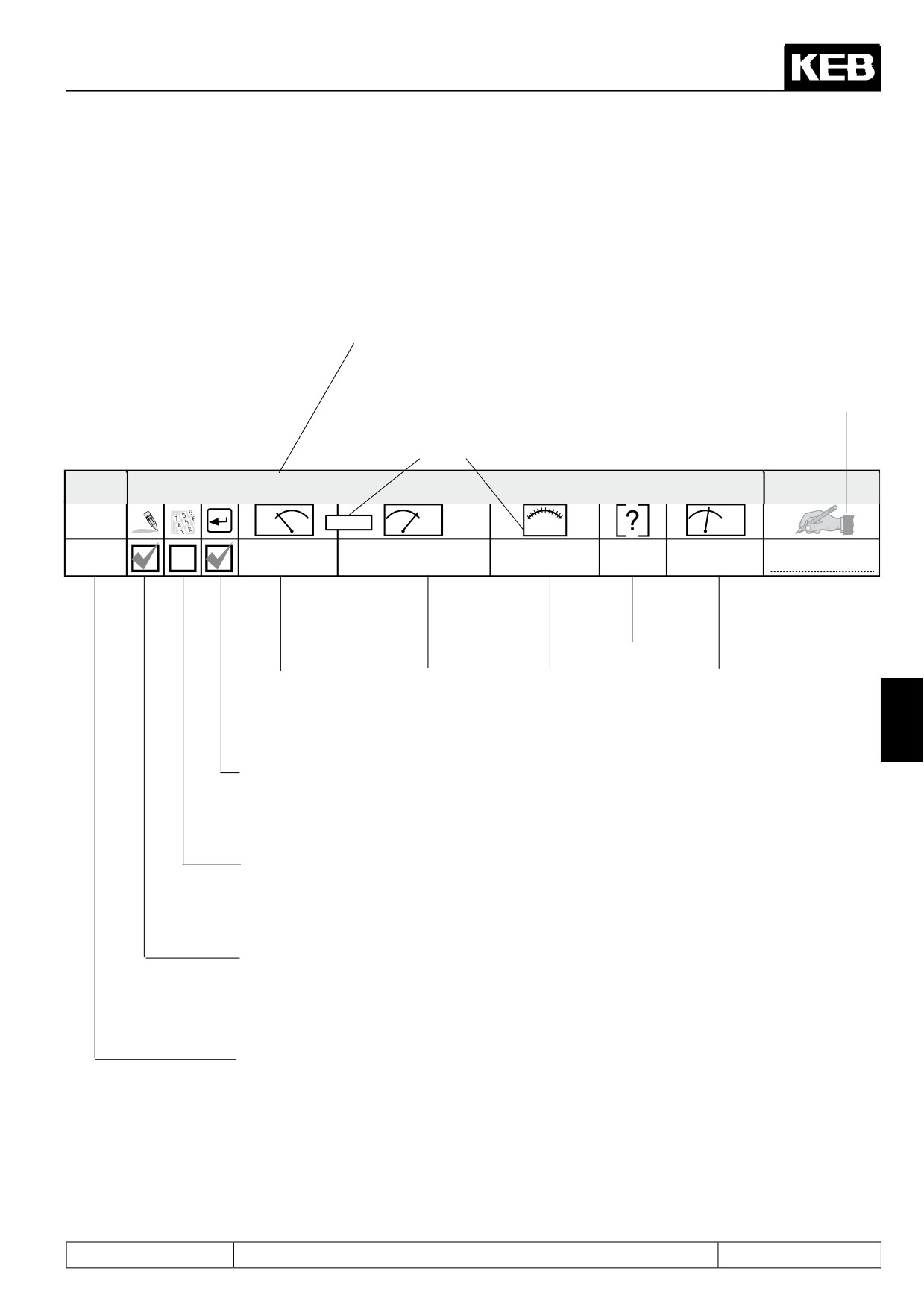
The parameters described in the following receive a symbol line with following details
for a better overview:
Parameter group, parameter number and parameter name
Resolution and value
Free for user adjustments
range depend on ud.2
ru.01
Set value display
Adr.
!ud.2!
min
max
!ud.2!
default
0201h
-400
400
0,0125
Hz
-
Value range
Unit
Lower limit
Upper limit Resolution,
Default value
increments
7
Enter parameter
after „Enter“ active
immediately active
Parameter
set-programmable
not programmable
Parameter
writable
read-only
Parameter address
Page7.1 - 5
Operating and Appliance Date
7.1.5
Description of the ru-parameters
ru.00
Inverter state
Adr.
min
max
default
0200h
0
255
1
-
0
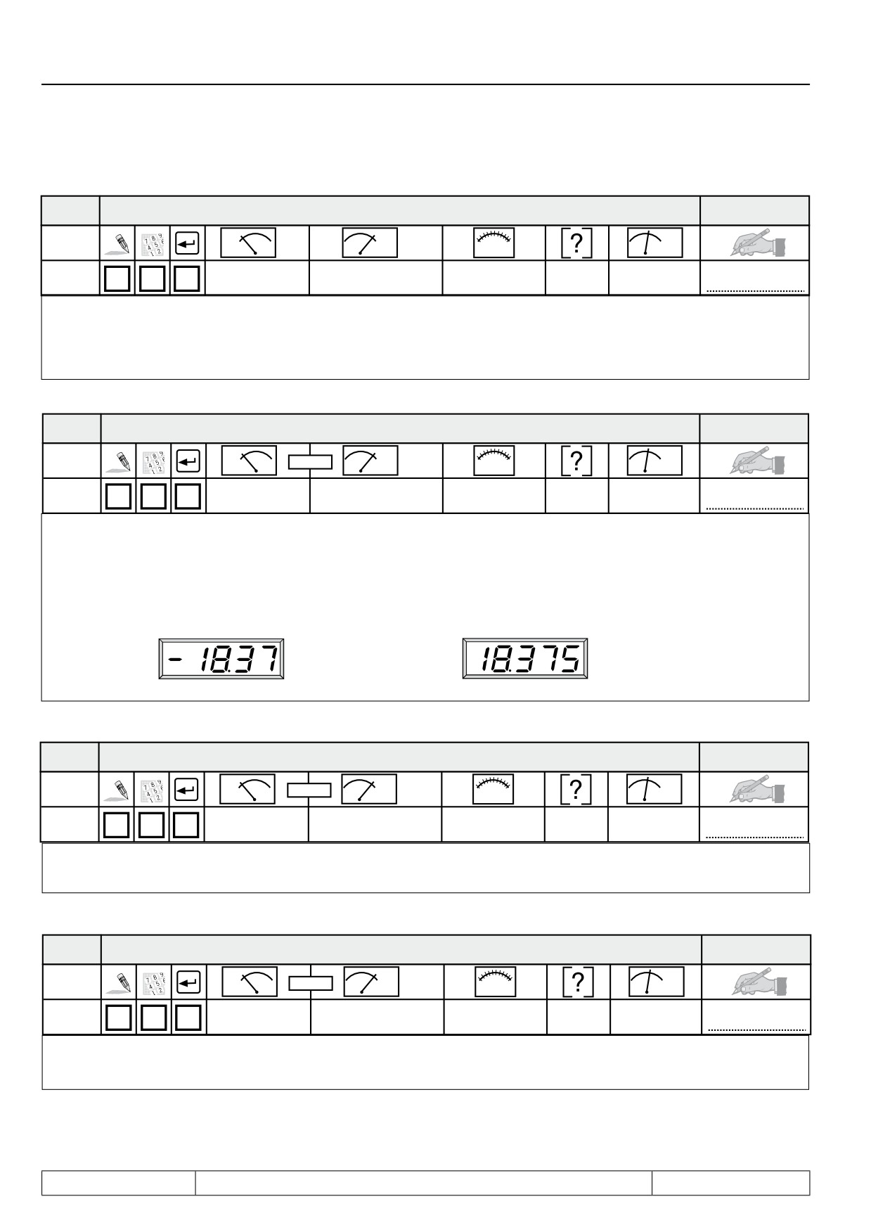
The inverter state shows the current operating condition of the inverter (e.g. constant forward run, standstill etc.). In
the case of an error the current error message is displayed, even if the display has already been reset with ENTER
(error-LED on the operator is still blinking). For more information about status messages as well as its cause and
removal refer to Chapter 8 „Error Diagnosis“.
ru.01
Set value display
Adr.
!ud.2!
min
max
!ud.2!
default
0201h
-4000
4000
0,125
rpm
-
Display of the actual set speed. For control reasons the set speed is displayed even if control release or direction of
rotation are not switched. If no direction of rotation is set, the set speed for clockwise rotation (forward) is displayed.
A counter-clockwise rotary field (reverse) is represented by a negative sign. Precondition is the phase-correct con-
nection of the motor.
Counter-clockwise
Clockwise
rotation
rotation
(reverse)
(forward)
ru.02
Ramp output display
Adr.
!ud.2!
min
max
!ud.2!
default
0202h
-4000
4000
0,125
rpm
-
The indicated actual speed corresponds to the rotary field speed given out at the ramp output. The representation is
the same as at ru.01.
ru.03
Actual frequency display
Adr.
!ud.2!
min
max
!ud.2!
default
0203h
-400
400
0,0125
Hz
-
The indicated actual frequency corresponds to the rotary field frequency given out at the inverter output. The repre-
sentation is the same as at ru.01.
Page7.1 - 6
Operating and Appliance Date
ru.07
Actual value display
Adr.
!ud.2!
min
max
!ud.2!
default
0207h
-4000
4000
0,125
rpm
-
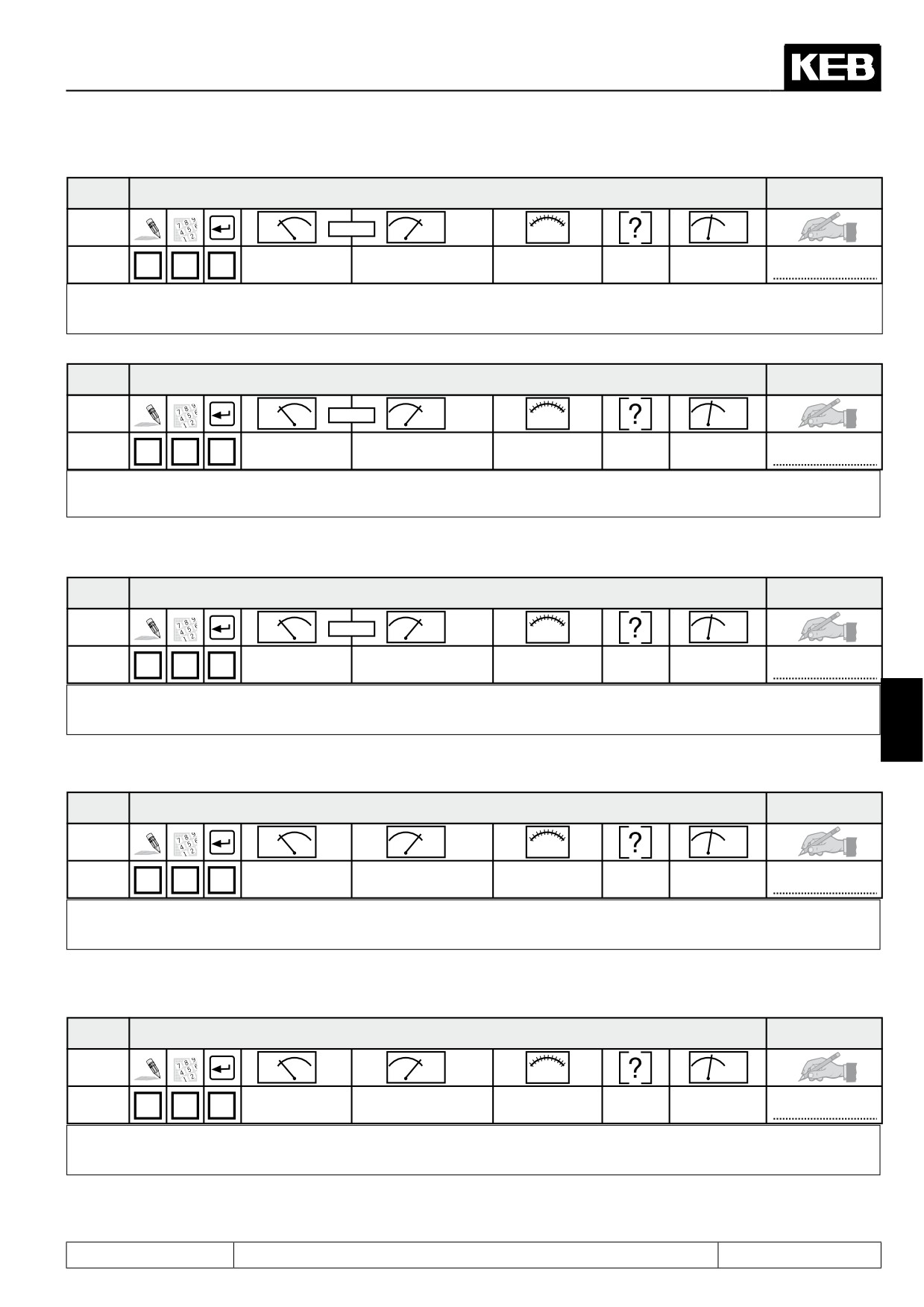
Depending on the adjusted actual source (cS.01) the actual speed of encoder input 1 and/or 2 is displayed.
ru.09
Encoder 1 speed
Adr.
!ud.2!
min
max
!ud.2!
default
0209h
-4000
4000
0,125
rpm
-
The displayed speed corresponds to the actual speed measured at the encoder input 1.
ru.10
Encoder 2 speed
Adr.
!ud.2!
min
max
!ud.2!
default
020Ah
-4000
4000
0,125
rpm
-
The displayed speed corresponds to the actual speed measured at the encoder input 2.
7
ru.11
Set torque display
Adr.
min
max
!ud.2!
default
020Bh
-10000
10000
0,01
Nm
-
The indicated value corresponds to the current set torque.
ru.12
Actual torque display
Adr.
min
max
!ud.2!
default
020Ch
-10000
10000
0,01
Nm
-
The indicated value corresponds to the actual torque.
Page7.1 - 7
Operating and Appliance Date
ru. 13
Actual utilization
Adr.
min
max
default
020Dh
0
65535
1
%
-
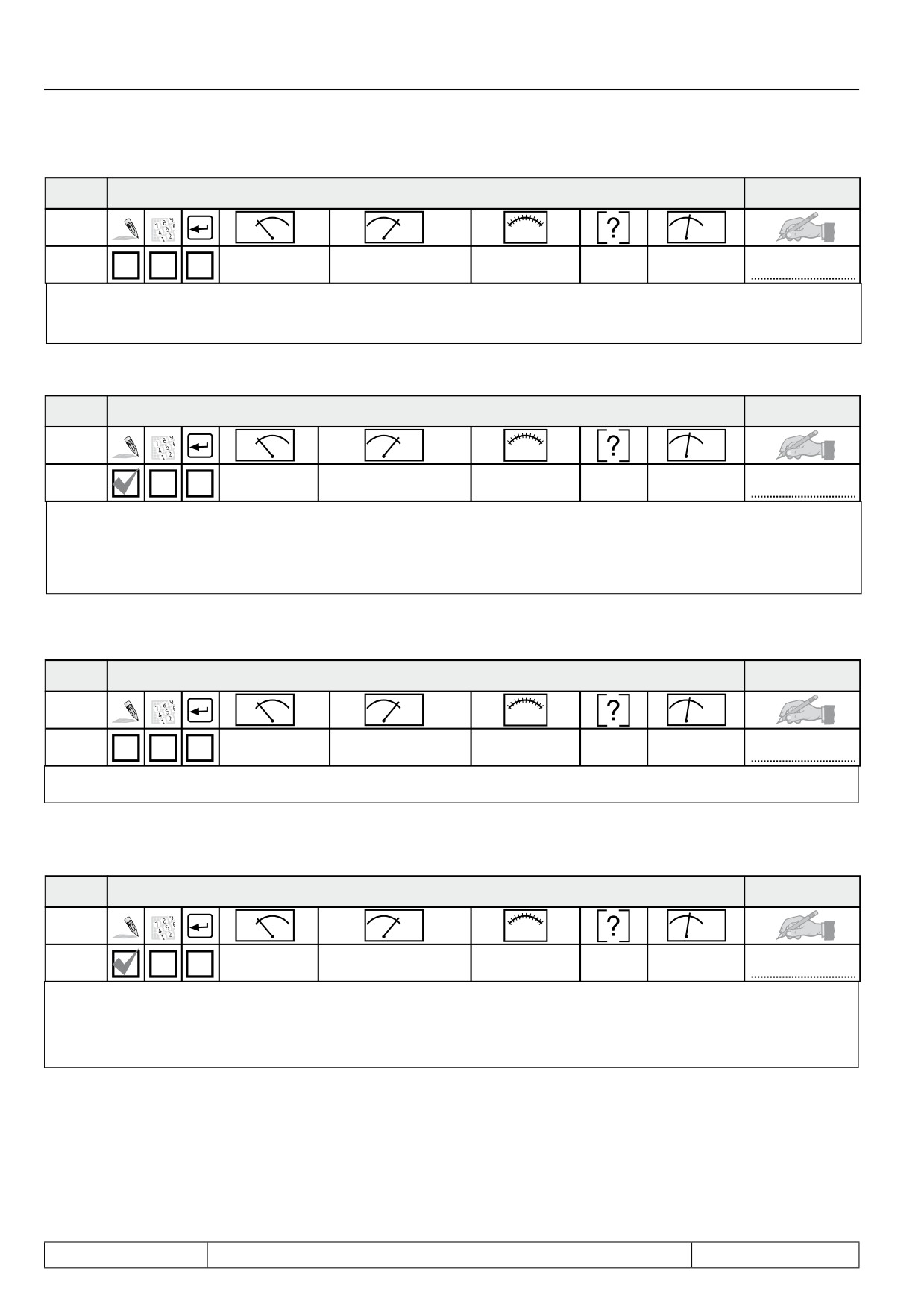
Display of the current utilization referred to the rated current of the inverter. Only positive values are indicated, thus it
is not possible to differentiate between a motoric or generatoric operation.
ru. 14
Peak utilization
Adr.
min
max
default
020Eh
0
65535
1
%
-
ru.14 permits the detection of short-time peak loads within an operating cycle. The highest occurred value of ru.13 is
stored in ru.14. The peak value memory can be cleared by pressing the keys UP, DOWN or ENTER and by bus through
writing any chosen value to the address of ru.14. The switch off of the inverter also clears the memory.
ru.15
Apparent current
Adr.
min
max
default
020Fh
0
6553,5
0,1
A
-
Display of the current apparent current.
ru.16
Peak apparent current
Adr.
min
max
default
0210h
0
6553,5
0,1
A
-
ru.16 permits the detection of short-time peak currents within an operating cycle. The highest occurred value of ru.15
is stored in ru.16. The peak value memory can be cleared by pressing the keys UP, DOWN or ENTER and by bus
through writing any chosen value to the address of ru.16. The switch off of the inverter also clears the memory.
Page7.1 - 8
Operating and Appliance Date
ru.17
Active current
Adr.
min
max
default
0211h
- 3276,7
3276,7
0,1
A
-
Display of the torque-forming active current. Negative current corresponds to generatoric operation, positive current
corresponds to motoric operation. The more precise the motor data are entered, the more precise is the indication of
the active current. The maximum values depend on the size of the inverter.
ru.18
Actual DC voltage
Adr.
min
max
default
0212h
0
1000
1
V
-
Display of current DC-link voltage. Typical values:
Normal operation: 230V-class approx. 300-330V Over volt. (E.OP) approx. 400 V Under volt. (E.UP) approx. 216 V
400V-class approx. 530-620V
approx. 800 V
approx. 240 V
ru.19
Peak DC voltage
Adr.
min
max
default
0213h
0
1000
1
V
-
7
ru.19 permits the detection of short-time voltage rises within an operating cycle. The highest occurred value of ru.18 is
stored in ru.19. The peak value memory can be cleared by pressing the keys UP, DOWN or ENTER and by bus through
writing any chosen value to the address of ru.19. The switch off of the inverter also clears the memory.
ru.20
Output voltage
Adr.
min
max
default
0214h
0
778
1
V
-
Display of the current output voltage.
Page7.1 - 9
Operating and Appliance Date
ru.21
Input terminal state
Adr.
min
max
default
0215h
0
4095
1
-
-
Display of the digital inputs controlled currently. The logic levels are indicated at the input terminals or at the internal
inputs regardless of the following logic operations (also see Chapt. 7.3 „Digital inputs“). According to following table a
specific decimal value is given out for each digital input. If several inputs are controlled, the sum of the decimal values
is indicated.
Bit -No.
Decimal value
Input
Terminal
0
1
ST (prog. input „control release/reset“)
X2A.16
1
2
RST (prog. input „reset“)
X2A.17
2
4
F (prog. input „forward“)
X2A.14
3
8
R (prog. input „reverse“)
X2A.15
4
16
I1 (prog. input 1)
X2A.10
5
32
I2 prog. input 2)
X2A.11
6
64
I3 (prog. input 3)
X2A.12
7
128
I4 (prog. input 4)
X2A.13
8
256
IA (internal input A)
no
9
512
IB (internal input B)
no
10
1024
IC (internal input C)
no
11
2048
ID (internal input D)
no
ru.22
Internal input state
Adr.
min
max
default
0216h
0
4095
1
-
-
Display of the digital external and internal inputs set currently. The input is only regarded as set if it is available as
effective signal to the further processing (i.e. accepted through strobe, edge-triggering or logic operation). According
to table like ru.21 a specific decimal value is given out for each digital input. If several inputs are controlled, the sum
of the decimal values (see ru.21) is indicated (also see Chapt. 7.3 „Digital inputs“).
Page7.1 - 10
Operating and Appliance Date
ru.23
Output condition state
Adr.
min
max
default
0217h
0
255
1
-
-
With parameters do.0...do.7 switching conditions can be selected, that serve as a base for setting the outputs. This
parameter indicates which of the selected switching conditions are met before they are linked or inverted by program-
mable logic (also see Chapt. 7.3. „Digital outputs“). According to following table a specific decimal value is given out
for the switching conditions. If several of the selected switching conditions are met, the sum of the decimal values is
indicated.
Bit -No.
Decimal value
Output
0
1
switching condition 0 (do.0)
1
2
Switching condition 1 (do.1)
2
4
Switching condition 2 (do.2)
3
8
Switching condition 3 (do.3)
4
16
Switching condition 4 (do.4)
5
32
Switching condition 5 (do.5)
6
64
Switching condition 6 (do.6)
7
128
Switching condition 7 (do.7)
ru.24
State of output flags
7
Adr.
min
max
default
0217h
0
255
1
-
-
Display of the output flags after logic step 1. The selected switching conditions are linked in logic step 1 (do.8...24) and
indicated here (see Chapt. 7.3 „Digital outputs“). According to following table a specific decimal value is given out for
any output flags. If several output flags are set, the sum of the decimal values is indicated.
Bit -No.
Decimal value
Output
0
1
Flag 0
1
2
Flag 1
2
4
Flag 2
3
8
Flag 3
4
16
Flag 4
5
32
Flag 5
6
64
Flag 6
7
128
Flag 7
Page7.1 - 11
Operating and Appliance Date
ru.25
Output terminal state
Adr.
min
max
default
0218h
0
255
1
-
-
Display of the external and internal digital output set currently. According to following table a specific decimal value is
given out for each digital output. If several outputs are set, the sum of the decimal values is indicated.
Bit -No.
Decimal value
Output
Terminal
0
1
O1 (transistor output 1)
X2A.18
1
2
O2 (transistor output 2)
X2A.19
2
4
R1 (relay RLA,RLB,RLC)
X2A.24...26
3
8
R2 (relay FLA,FLB,FLC)
X2A.27...29
4
16
OA (internal output A)
no
5
32
OB (internal output B)
no
6
64
OC (internal output C)
no
7
128
OD (internal output D)
no
ru.26
Active parameter set
Adr.
min
max
default
021Ah
0
7
1
-
-
The KEB COMBIVERT can have access to 8 parameter sets (0-7). Through programming the inverter can change
parameter sets autonomously and can thus start different modes of operation. This parameter shows the parameter
set, with which the inverter is operating currently. Independent of it another parameter set can be edited by bus (also
see chapter 7.14).
ru.27
AN1 pre amplifier display
Adr.
min
max
default
021Bh
-100
100
0,1
%
-
This parameter indicates the value of the analog signal AN1 on the differential voltage input (terminal X2A.1 / X2A.2)
before signal amplification in percent. In dependence on An.0 the indicated value 0...±100 % corresponds to: 0...±10 V;
0...±20 mA or 4...20 mA (also see chapt. 7.2 „Analog inputs“).
ru.28
AN1 post amplifier display
Adr.
min
max
default
021Ch
-400
400
0,1
%
-
This parameter shows the value of the analog signal AN1 in percent after passing the characteristic amplifier. The
range of indication is limited to ±400 % (also see chapt. 7.2 „Analog inputs“).
Page7.1 - 12
Operating and Appliance Date
ru.29
AN2 pre amplifier display
Adr.
min
max
default
021Dh
-100
100
0,1
%
-
This parameter shows the value of the analog signal AN2 on the differential voltage input (terminal X2A.3 / X2A.4) before
signal amplification in percent. In dependence on An.10 the indicated value of 0...±100 % corresponds to: 0...±10 V;
0...±20 mA or 4...20 mA (also see chapt. 7.2 „Analog inputs“).
ru.30
AN2 post amplifier display
Adr.
min
max
default
021Eh
-400
400
0,1
%
-
This parameter shows the value of the analog signal AN2 in percent after passing the characteristic amplifier. The
range of indication is limited to ±400 % (also see chapt. 7.2 „Analog inputs“).
ru.31
AN3 pre amplifier display
Adr.
min
max
default
021Fh
-100
100
0,1
%
-
This parameter shows the value of the analog signal on the optionally analog input AN3 before signal amplification
7
in percent. In dependence on An.10 the indicated value of 0...±100 % corresponds to: 0...±10 V (see also chapt. 7.2
„Analog inputs“).
ru.32
AN3 post amplifier display
Adr.
min
max
default
0220h
-400
400
0,1
%
-
This parameter shows the value of the analog signal on the optionally analog input AN3 after signal amplification in
percent. The range of indication is limited to ±400 % (also see chapt. 7.2 „Analog inputs“).
Page7.1 - 13
Operating and Appliance Date
ru.33
ANOUT1 pre amplification display
Adr.
min
max
default
0221h
-400
400
0,1
%
-
This parameter shows the value of the analog signal ANOUT1 in percent before passing the characteristic amplifier
(also see 7.2 „Analog outputs“).
ru.34
ANOUT1 post amplification display
Adr.
min
max
default
0222h
-115
115
0,1
%
-
This parameter shows the value of the signal given out on analog output ANOUT1 (terminal X2A.5) in percent. A value
of
0...±100 % correponds to an output signal of 0...±11,5 V (also see chapt. 7.2 „Analog outputs“).
ru.35
ANOUT2 pre amplification display
Adr.
min
max
default
0223h
-400
400
0,1
%
-
This parameter shows the value of the analog signal ANOUT1 in percent before passing the characteristic amplifier
(also see 7.2 „Analog outputs“).
ru.36
ANOUT2 post amplification display
Adr.
min
max
default
0224h
-115
115
0,1
%
-
This parameter shows the value of the signal given out on analog output ANOUT2 (terminal X2A.6) in percent. A value
of
0...±100 % correponds to an output signal of 0...±11,5 V (also see chapt. 7.2 „Analog outputs“).
ru.37
Motorpoti actual value
Adr.
min
max
default
2025h
-100
100
0,01
%
-
The motorpoti-function in the KEB COMBIVERT imitates a mechanical, motor operated potentiometer. The control
occurs via 2 programmable inputs („poti up“ and „poti down“). The display is limited by oP.53/54. The adjustment of the
motorpoti is done with the parameters oP.50...oP.59 (also see chapt. 15.3 „Motorpoti“). By way of the bus the motorpoti
can be set to any chosen value between -100...100%. In addition to the inputs the motorpoti can be operated with the
keys „UP“ and „DOWN“. Then the rate of change is not constant.
Page7.1 - 14
Operating and Appliance Date
ru.38
Power module temperature
Adr.
min
max
default
0226h
0
150
1
°C
-
ru.38 shows the current power module temperature of the inverter.
ru.39
OL counter display
Adr.
min
max
default
0227h
0
100
1
%
-
In order to preclude „E.OL“ - errors by too high load (load reduction in due time), the internal count of the OL-counter
can be made visible with this indication. At 100 % the inverter switches off with error „E.OL“. The error can be reset
only after a cooling time (blinking display „E.nOL“).
ru.40
Power on counter
Adr.
min
max
default
0228h
0
65535
1
h
-
The operating power on counter shows the time the inverter was switched on. The indicated value comprises all ope-
rating phases. On reaching the maximum value (approx. 7.5 years) the indication remains on the maximum value.
ru.41
Modulation on counter
7
Adr.
min
max
default
0229h
0
65535
1
h
-
The modulation on counter shows the time the inverter was active (power modules controlled). On reaching the maxi-
mum value (approx. 7.5 years) the indication remains on the maximum value.
ru.42
Modulation grade
Adr.
min
max
default
022Ah
0
110
1
%
-
The modulation factor shows the output voltage in percent. 100 % correspond to the input voltage (no-load). At a value
of
> 100 % the inverter works with overmodulation.
ru.43
Timer 1 display
Adr.
min
max
default
022Bh
0
655,35
0,01
-
-
The count of the free-programmable timer 1 is indicated. The display is done either in seconds, in hours or in slopes/100
(see LE.21). The counter can be adjusted to any chosen value by keyboard or bus. The programming of the counter
is done with the parameters LE.17...LE.21 (also see chapt. 7.15.4 „Timer“).
Page7.1 - 15