KEB COMBIVERT F5-A,-E,-H 4.0. APPLICATION MANUAL (2008) - page 3
Selection of Operating Mode
Page5.1 - 6
Preparatory Measures
1.
Introduction
2.
Summary
3.
Hardware
6.1
Preparatory measures
4.
Operation
Selection of Operating
5.
Mode
6.
Initial Start-up
6
7.
Functions
8.
Error Assistance
9.
Project Design
6.2
Start-up
10. Networks
11. Parameter Overview
12. Annex
Page6.1 - 1
Preparatory Measures
6.1.1
After unpacking the goods
6.1 - 3
6.1.2
Installation and connection
6.1 - 3
6.1.3
Checklist prior to start-up
6.1 - 4
Page6.1 - 2
Preparatory Measures
6.
Start-up
The following chapter is intended for everybody who has no experience with the KEB frequency inverters. It
shall allow a correct entering into this field. But because of the complex application possibilities we must restrict
ourselves to explaining the start-up of standard applications.
6.1
Preparatory measures
6.1.1
After unpacking the goods
After unpacking the goods and checking them for complete delivery following measures are to be carried out:
Visual control for transport damage
Should any external damages to the KEB COMBIVERT be visible get in tough with your forwarding agent
and return the unit with a corresponding report to KEB.
Check the voltage class:
Absolute check before assembly whether the supply voltage of the KEB COMBIVERT matches the applica-
tion.
6.1.2
Installation and connection
6
The EMC-conform installation of the inverter is described in the Instruction Manual Part 1. Installation and con-
nection instructions are found in the instruction manual part 2.
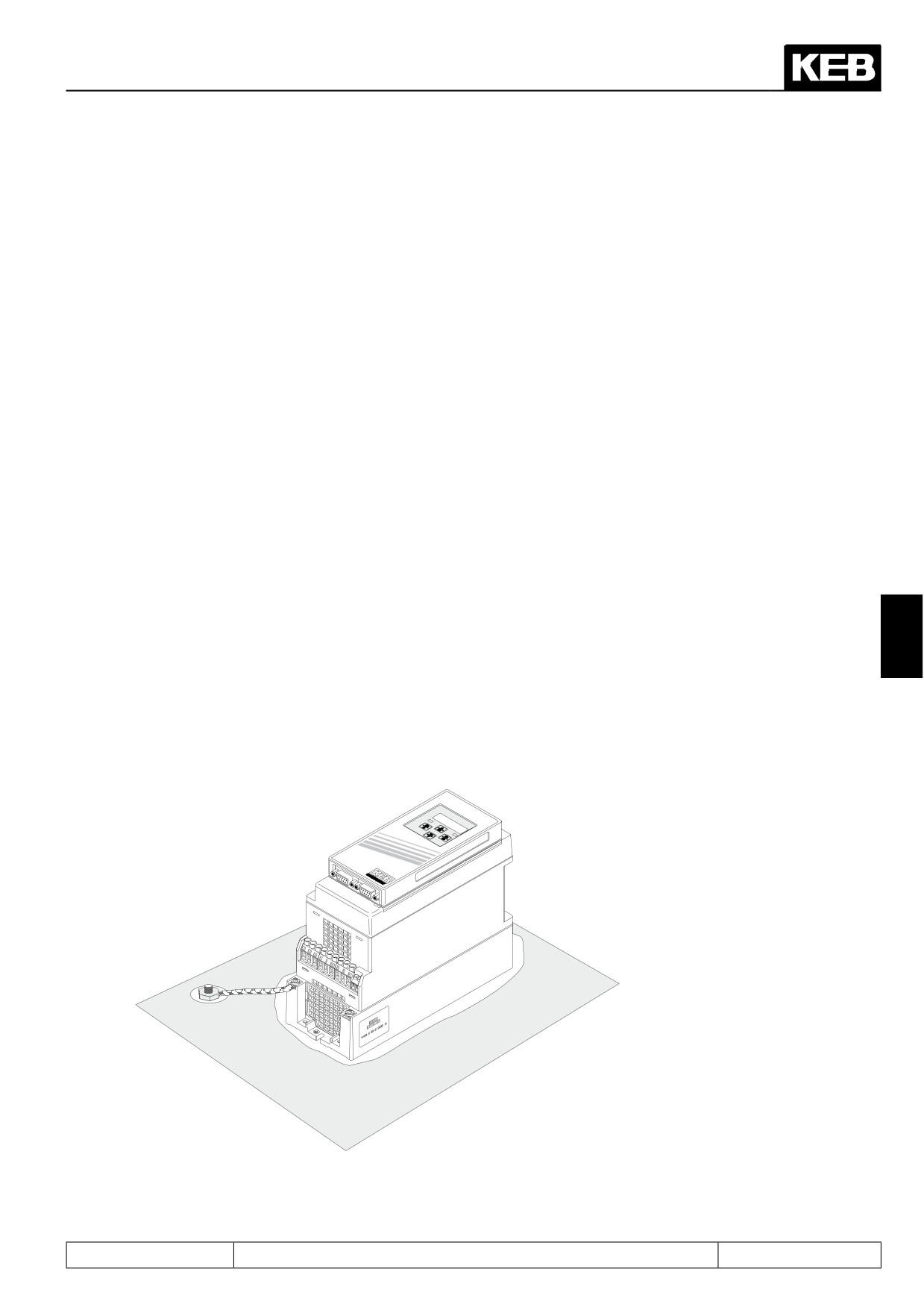
The mounting surface of the inverter must be bright.
If necessary, use contact lacquer as protection against corrosion.
Connect the earthing strip to central point in the control cabinet
Picture 6.1.3 Installation and connection
Page6.1 - 3
Preparatory Measures
6.1.3
Checklist prior to start-up
Before switching on the inverter go through the following checklist.
Is the inverter firmly bolted in the control cabinet?
Is there enough space to ensure sufficient air circulation?
Are mains and motor cables as well as the control cables installed separately from each other?
Are the inverters connected to the correct supply voltage?
Are all mass and earthing cables attached and well contacted?
Ensure that mains and motor cables are not interchanged as that will lead to the destruction of
the inverter!
Is the motor connected in phase?
Check tacho, initiator and encoder for firm attachment and correct connection!
Check, whether all power and control cables are firmly in place!
Remove any tools from the control cabinet!
Attach all covers and protective caps to ensure that all live parts are secured against direct
contact.
When using measuring instruments or computers an isolating transformer should be used, if not,
make sure that the equipotential bonding between the supply lines is guaranteed!
Open the control release of the inverter to avoid the unintended starting of the machine.
Page6.1 - 4
Start-up
1.
Introduction
2.
Summary
3.
Hardware
6.1
Preparatory measures
4.
Operation
Selection of Operating
5.
Mode
6.
Initial Start-up
6
7.
Functions
8.
Error Assistance
9.
Project Design
6.2
Start-up
10. Networks
11. Parameter Overview
12. Annex
Page6.2 - 1
Start-up
6.2.1
Start-up of an asynchronous motor
6.2 - 3
6.2.1.1
V/F characteristic operation
6.2 - 4
6.2.1.2
Vector controlled operation with encoder feedback without motor model
6.2 - 6
6.2.1.3
Vector controlled operation with encoder feedback with motor model
6.2 - 9
6.2.1.4
Start-up F5H-M (ASCL/ vector controlled without encoder
feedback with motor model)
6.2 - 12
6.2.2
Start-up of a synchronous motor
6.2 - 16
6.2.2.1
Start-up F5A-S
6.2 - 16
6.2.2.2
Start-up F5E-S (SCL)
6.2 - 18
Page6.2 - 2
Start-up
6.2
Initial start-up
After all preparatory measures have been carried out and checked the KEB COMBIVERT F5 can be switched
on.
The control release ST (X2A.16) must be deactivated when switching on the first time, since the frequency
inverter is not custom-specific parameterized.
The following descriptions suppose that the frequency inverter is on the password level "application mode"
(ud.01 = application mode). The selection of the password level is described in the manual chapter 4. The start-
up should be executed with COMBIVIS in order to have a short start-up time.
Operating lists are available on the KEB homepage (www.keb.de). This lists contain the necessary parameters
for start-up.
Attention: The start-up instruction manual can only give a short overview of the parameter adjustments which
are mandatory necessary to start-up the motor.
Thus it represents a check list and not a complete parameter description.
The appropriate chapters of the application manual must be read carefully for exact information about the pa-
rameters, additionally points to consider and application-specific adjustments!
The wiring of the motor must be checked before start-up:
-
in-phase connection (inverter terminals U, V, W must be connected at the motor terminal board with the
appropriate contacts)
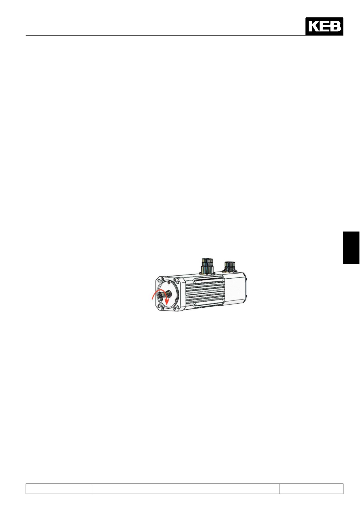
If the wiring is correct the following direction of rotation occurs at setting "clockwise rotation":
6
-
large surface of shield connection, well grounding (see „EMC conform wiring“ in the manual „… before
start-up“)
6.2.1
Start-up of an asynchronous motor
The following chapters describe the start-up of an asynchronous motor in the 4 available modes:
•
V/F characteristics open loop operation (F5A-M)
•
speed-controlled operation with encoder feedback without motor model (F5A-M)
•
speed-controlled operation with encoder feedback with motor model (F5A-M) (recommended operating
mode when using a speed feedback)
•
speed-controlled operation without encoder feedback (ASCL / F5H-M)
Page6.2 - 3
Start-up
6.2.1.1V/F characteristic operation
1.
Open control release
Deactivate terminal X2A.16
→ Inverter state ru.00 = „noP“/„0:no control release“
2.
Selection of the speed range
The required speed range (e.g.: 0..+/- 4000 rpm) is selected in
Attention: Changing the controller type
control type ud.02.
releases loading of the default para-
meters!
→ ud.02 control type = 4…7
The speed range should be selected
at least 10% higher than the highest
All data for the adjustment of the controller type (e.g. resolution
setpoint speed in the application.
of the speed, etc.) see chapter 5.1
3.
Loading the default parameters
Loading the default parameters (KEB factory setting) by
Attention: Pre-adjustments (e.g. func-
tion of the digital inputs) disappear
→ Fr.01 copy parameter set = - 4
4.
Selection of the controller configuration
Adjust V/F characteristic operation
→ CS.00 speed control config. = 0: off
(default V/F characteristic operation)
Motor data are not necessary for standard V/F characteristic
operation.
The following parameters must be examined if SMM (sensor-
less motor management for speed stabilization during load)
should not be used:
Frequency when the highest voltage is output:
→ uF.00 rated frequency
Voltage [in%], which is output at 0Hz:
→ uF.01 boost
If these adjustments for the motor are made correctly continue
to proceed at point 9.
Page6.2 - 4
Start-up
5.
Input of the motor data
Values dr.00 to dr.05 must be taken from the motor name
plate.
The value for dr.06 can be identified automatically (see point
6).
→ dr.00 DASM rated current
→ dr.01 DASM rated speed
→ dr.02 DASM rated voltage
→ dr.04 DASM rated cos (phi)
→ dr.05 DASM rated frequency
→ dr.06 DASM stator resistance
6.
Calibration of the stator resistance
The stator resistance dr.06 can be determined automatically
by the KEB COMBIVERT.
Inverter must be in status „70: standstill (modulation off)“. Start
measurement with the input of
→ dr.06 = 250000: on
Open control release (X2A.16) after the measurement is finis-
hed
6
7.
Calculation of motor-dependent data
Activation of SMM, as well as the adaption of the U/f characte-
ristic is made by the input of:
→ Fr10 load mot. dependent parameter = 3
8.
Adjust speed controller
The speed controller must be adapted to the application via
cS.06 and cS.09.
9.
Enter application specific data
e.g. limit values (speed limits, torque limits etc.)
Proper data for the adaption of the in-
acceleration- / deceleration ramps,
verter to the respective application can
function of the digital in- / outputs,
be find in the corresponding chapters
Type of speed setpoint setting etc.
10.
Test run
Test run, in order to check whether the drive runs stable in all
speed ranges and under all load conditions and if a sufficient
safety distance to the power limits is available etc.
Page6.2 - 5
Start-up
6.2.1.2Vector controlled operation with encoder feedback without motor model
With this start-up description it is provided that an incremental encoder to encoder interface 1 (Sub-D15 socket
X3A) is used for speed feedback.
Read chapter 7.11 "Speed measurement" for necessary adjustments of your speed encoder when using ano-
ther encoder type.
Also it must be secured that the motor phases and the incremental encoder are correct wired (in phase, large
surface of shield connection, well earth connection). The motor temperature sensor must be connected.
A controlled start-up (V/F characteristic) of the drive can be executed for examination in case of insecurity about
the phase allocation (motor and incremental encoder).
1.
Open control release
Deactivate terminal X2A.16
→ inverter state ru.00 = „noP“/„0: no control release“
2.
Selection of the speed range
The required speed range (e.g.: 0..+/- 4000 rpm) is selected
Attention: Changing the controller type
in control type ud.02.
releases loading of the default parame-
ters!
→ ud.02 control type = 4…7
All data for the adjustment of the con-
troller type (e.g. resolution of the speed,
The speed range should be selected at least 10% higher than
etc.) see chapter 5.1
the highest setpoint speed in the application.
3.
Loading the default parameters
Loading the default parameters (KEB factory setting) by
Attention: Pre-adjustments (e.g. func-
tion of the digital inputs) disappear
→ Fr.01 copy parameter set = - 4
4.
Selection of the controller configuration
Adjust speed-controlled operation
→ CS.00 speed control config. = 4
(control mode = speed control)
5.
Select source of the speed feedback
The motor speed feedback must be connected to Sub-D so-
cket X3A.
→ cS.01 act. source = 0:channel 1
6.
Enter increments per revolution of the speed feedback
Page6.2 - 6
Start-up
Enter the number of increments per revolution according to
Note: Further adjustments are neces-
the name plate of the encoder
sary when using another encoder type.
Read chapter
7.11 speed measure-
→ Ec.01 encoder 1 (inc/r)
ment
7.
Input of the motor data
Values dr.00 to dr.05 must be taken from the motor name
Note:
plate.
The equivalent circuit data dr.06..dr.10
are without meaning
→ dr.00
→ dr.01
→ dr.02
→ dr.03
→ dr.04
→ dr.05
8.
Activate maximum voltage controller
The maximum voltage controller must be activated for the
Attention: Further adjustments must be
field-weakening range if the motor reaches the voltage limita-
done in connection with the maximum
tion (modulation grade ru.42 = 100%).
voltage controller.
→ dS.04 = 24
6
Parameterization of the controller,
Activation of the active current limitation in the field-weake-
ning range
9.
Calculation of motor-dependent data
Adaption of the adjustments to the motor
Note:
Since the equivalent circuit data are
→ Fr10 load mot. dependent parameter = 2: actual DC link
unknown at this control type, the cur-
voltage
rent controllers cannot be optimally ad-
apted to the motor, as per control with
motor model.
Page6.2 - 7
Start-up
10. Enter application specific data
Application specifc data are e.g.
Proper data for the adaption of the in-
verter to the respective application can
•Limit values (speed limits, etc.)
be find in the corresponding chapters.
→ oP parameter (chapter 7.4.5 setpoint limits)
•Acceleration- / deceleration ramps
→ oP parameter (chapter 7.4.7 ramp generator)
•Function of the digital in- / outputs
→ di parameter (chapter 7.3 digital in- and outputs)
•Type of speed setpoint setting
→ oP parameter (chapter 7.4.2, 7.4.3, 7.4.6)
11. Adjust speed controller
The speed controller parameters must be adapted to the ap-
plication
The maximum voltage controller must be parameterized if the
field weakening range is used.
12. Test run
Activate control release (terminal X2A.16) and make a test
run, whether the drive runs stable in all speed ranges and
under all load conditions
If error messages occur during the start-up phase, read chapter 8.1 "Error causes and displays"
Page6.2 - 8
Start-up
6.2.1.3Vector controlled operation with encoder feedback with motor model
Attention: With this start-up description it is provided that an incremental encoder to encoder interface 1 (Sub-
D15 socket X3A) is used for speed feedback.
Also it must be secured that the motor phases and the incremental encoder are correct wired (in phase, large
surface of shield connection, well grounding).
The motor temperature sensor must be connected.
A controlled start-up (V/F characteristic) of the drive can be executed for examination in case of insecurity about
the phase allocation (motor and incremental encoder).
1.
Open control release
Deactivate terminal X2A.16
→ Inverter state ru.00 = „noP“/„0: no control release“
2.
Selection of the speed range
The required speed range (e.g.: 0..+/- 4000 rpm) is selected
Attention: Changing the controller type
in control type ud.02.
releases loading of the default parame-
ters!
→ ud.02 control type = 4…7
All data for the adjustment of the con-
troller type (e.g. resolution of the speed,
The speed range should be selected at least 10% higher
etc.) see chapter 5.1
than the highest setpoint speed in the application.
6
3.
Loading the default parameters
Loading the default parameters (KEB factory setting) by
Attention: Preadjustments
(e.g. func-
tion of the digital inputs) disappear.
→ Fr.01 copy parameter set = - 4
4.
Selection of the controller configuration
Adjust speed-controlled operation
→ cS.00 speed control config. = 4
(control mode = speed control)
5.
Select source of the speed feedback
The motor speed feedback must be connected to Sub-D so-
cket X3A.
→ cS.01 actual source = 0: channel 1
6.
Enter increments per revolution of the speed feedback
Enter the number of increments per revolution according to
Note: Further adjustments are neces-
the name plate of the encoder
sary when using another encoder type.
Read chapter 7.11 speed measure-
→ Ec.01 encoder 1 (inc/r)
ment
Page6.2 - 9
Start-up
7.
Input of the motor data
Values dr.00 to dr.05 must be taken from the motor name
Attention: The interconnection of the
plate.
motor must be considered at accep-
The values for dr.06 upto dr.08 can be taken from the motor
tance of the values of the motor data
data sheet (if available) or they can be identified automatical-
sheet. The data sheet contains mostly
ly (see point 10).
phase values. The phase-phase values
The DASM head-inductance (dr.10) should always be iden-
must be entered in parameters dr.06...
tified, because it is dependent on the selected magnetizing
dr.10.
current.
The default values can remain in dr.06
→ dr.00 DASM rated current
to dr.10 up to the identification if no
→ dr.01 DASM rated speed
equivalent circuit data are known.
→ dr.02 DASM rated voltage
→ dr.03 DASM rated power
→ dr.04 DASM rated cos (phi)
→ dr.05 DASM rated frequency
→ dr.06 DASM stator resistance
→ dr.07 DASM sigma-inductance
→ dr.08 DASM rotor resistance
→ dr.10 DASM head-inductance
8.
Parameterize flux/rotor adaptation mode
The operation with motor model is activated in parameter
Attention: Further adjustments must be
ds.04 flux/rotor adaptation mode.
done in connection with the maximum
voltage controller.
→ dS.04 = 249
Parameterization of the controller 7.9.1
Activation of the active current limitati-
Further necessary adjustments for the operation with motor
on in the field-weakening range 7.9.2
model are additionally made by this parameter:
Further information about the flux con-
• Maximum voltage controller, maximum voltage 100%
troller and flux build-up see chapter
(without overmodulation)
7.6.2.3.3.1
• Flux controller and magnetization build-up active before
start-up
9.
Calculation of motor-dependent data
The motor-dependent data (e.g. dr.18 field weak. speed)
must be calculated here, even if the motor data dr.06 to dr.10
are unknown.
→ Fr.10 load mot. dependent para. =
2:act. DC link vol-
tage
Page6.2 - 10
Start-up
10.
Identification of the equivalent circuit data
The equivalent circuit data dr.06..dr.10 can be automatically
Attention:
determined by the KEB COMBIVERT.
Depending on the used motor the iden-
The following must be considered:
tification takes some minutes. Noises
• The motor must be in no-load operation for identification
in the motor can occur caused by high
of the main inductance. As standard the motor rotates with
frequency test signals. The sequence
dr.17: "speed for max torque“.The speed limits (oP-parame-
of the identification can be tracked in
ter/chapter 7.4.5) must be programmed accordingly if this is
parameter dr.62 "state motor ident.".
not permissible.
Since the drive is not optimally parame-
• The direction of rotation is clockwise, the acceleration time
terized, a flat acceleration ramp (dr.49)
is preset by dr.49: „Lh.ident. acc/dec time“
should be selected for the identification
• The speeed controller must be parameterized for acce-
to avoid overload of the motor.
leration (dynamics not necessary => select small value for
Note:
cS.09: KI speed)
If the measurement is interrupted with
• The brake control mode must be activated
an error, ru.00 = 60 (error! drive data /
(corresponding to KEB factory setting)
E.Cdd) is displayed.
After successful measurement ru.00 = 127 "drive data calcu-
Read chapter 7.6 for further data of the
lated/Cddr" is displayed.
identification.
The identification is started with:
→ dr.48 = 8: complete AutoIdentification !with rotation!
Close control release (X2A.16) for starting the identification
and open it after the measurement.
6
11.
Adjustment of specific data
→ dS.02 Current decoupling = 1:on
→ uF.15 Hardw. curr. lim. mode = 0: off
→ uF.18 Deadtime comp. mode = 3: automatically
12.
Enter application specific data
Application specifc data are e.g.
Proper data for the adaption of the in-
• Limit values (speec limits, torque limits etc.)
verter to the respective application can
be find in the corresponding chapters.
→ oP parameter (chapter 7.4.5 setpoint limits)
→ CS parameter (chapter 7.8 torque display and limitation)
• Acceleration / deceleration ramps
→ oP parameter (chapter 7.4.7 ramp generator)
• Function of the digital in- / outputs
→ di parameter (chapter 7.3 digital in- and outputs)
• Type of speed setpoint setting
→ oP parameter (chapter 7.4.2, 7.4.3, 7.4.6) etc.
Page6.2 - 11
Start-up
13. Adjust speed controller
The speed controller parameters can be calculated by the
inverter for applications with constant inertia and rigidly cou-
pled load (see chapter 7.7.1).
The speed controller must be manually adapted, if this ad-
justment is not workable for the application or if the result is
nonsatisfying.
The maximum voltage controller must be parameterized, if
the field weakening range is used.
Note:
Current and flux controller are automatically adjusted during
identification.
14. Test run
Check whether the drive operates stable in all speed ranges
and under all load conditions.
If error messages occur during the start-up phase, read chapter 8.1 "Error causes and displays"
6.2.1.4Start-up F5H-M (ASCL/ vector controlled without encoder feedback with motor model)
Attention: The motor temperature sensor must be connected.
1.
Open control release
Deactivate terminal X2A.16
→ Inverter state ru.00 = „noP“/„0: no control release“
2.
Selection of the speed range
The required speed range (e.g.: 0..+/- 4000 rpm) is selected
Attention: Changing the controller type
in control type ud.02.
releases loading of the default para-
meters!
→ ud.02 control type = 4…7
All data for the adjustment of the
controller type (e.g. resolution of the
The speed range should be selected at least 10% higher
speed, etc.) see chapter 5.1
than the highest setpoint speed in the application.
Page6.2 - 12
Start-up
3.
Loading the default parameters
If the control type ud.02 was not changed, loading of the de-
Attention: Preadjustments (e.g. func-
fault parameters (KEB factory setting) can be released by
tion of the digital inputs) disappear
→ Fr.01 copy parameter set = - 4
4.
Selection of the controller configuration
Adjust speed-controlled operation
→ CS.00 speed control config. = 4
(control mode = speed control)
5.
Select source of the speed feedback
Motor speed feedback not available.
→ cS.01 actual source = 2: calculated actual value
6.
Input of the motor data
Values dr.00 to dr.05 must be taken from the motor name
Attention: The interconnection of the
6
plate.
motor must be considered at accep-
The values for dr.06 upto dr.08 can be taken from the motor
tance of the values of the motor data
data sheet (if available) or they can be identified automati-
sheet. The data sheet contains mostly
cally (see point 10).
phase values. The phase-phase va-
The DASM head-inductance (dr.10) should always be iden-
lues must be entered in parameters
tified, because it is dependent on the selected magnetizing
dr.06...dr.10.
current.
The default values can remain in dr.06
to dr.10 up to the identification if no
→ dr.00 DASM rated current
equivalent circuit data are known.
→ dr.01 DASM rated speed
→ dr.02 DASM rated voltage
→ dr.03 DASM rated power
→ dr.04 DASM rated cos (phi)
→ dr.05 DASM rated frequency
→ dr.06 DASM stator resistance
→ dr.07 DASM sigma-inductance
→ dr.08 DASM rotor resistance
→ dr.10 DASM head-inductance
Page6.2 - 13
Start-up
7.
Parameterize flux/rotor adaptation mode
The operation with motor model is activated in parameter
Attention: Further adjustments must be
ds.04 flux/rotor adaptation mode.
done in connection with the maximum
voltage controller. Parameterization of
→ dS.04 = 249
the controller,
Activation of the active current limitati-
Further necessary adjustments for the operation with motor
on in the field-weakening range 7.9.2.
model are additionally made by this parameter:
Further information about the flux con-
• Maximum voltage controller, maximum voltage 100%
troller and flux build-up see chapter
(without overmodulation)
7.6.2.3.3.1
• Flux controller and magnetization build-up active before
start-up
8.
Calculation of motor-dependent data
The motor-dependent data (e.g. dr.18 field weak. speed)
must be calculated here, even if the motor data dr.06 to
dr.10 are unknown.
→ Fr.10 load mot. dependent para. =
2:act. DC link vol-
tage
9.
Identification of the equivalent circuit data
The equivalent circuit data dr.06..dr.10 can be automatically
Attention:
determined by the KEB COMBIVERT.
Depending on the used motor the iden-
The following must be considered:
tification takes some minutes. Noises
• The motor must be in no-load operation for identification
in the motor can occur caused by high
of the main inductance. As standard the motor rotates with
frequency test signals. The sequence
dr.17: "speed for max torque“.The speed limits (oP-parame-
of the identification can be tracked in
ter/chapter 7.4.5) must be programmed accordingly if this is
parameter dr.62 "state motor ident.".
not permissible.
Since the drive is not optimally para-
meterized, a flat acceleration ramp
• The direction of rotation is clockwise, the acceleration time
(dr.49) should be selected for the iden-
is preset by dr.49: „Lh.ident. acc/dec time“
tification to avoid overload of the mo-
tor.
• The speeed controller must be parameterized for acce-
Note:
leration (dynamics not necessary => select small value for
If the measurement is interrupted with
cS.09: KI speed)
an error, ru.00 = 60 (error! drive data /
E.Cdd) is displayed.
• The brake control mode must be activated
Read chapter 7.6 for further data of the
(corresponding to KEB factory setting)
identification
After successful measurement ru.00 = 127 "drive data cal-
culated/Cddr" is displayed.
The identification is started with
→ dr.48 = 8:complete AutoIdentification !with rotation!
Close control release (X2A.16) for starting the identification
and open it after the measurement.
Page6.2 - 14
Start-up
10.
Adjustment of specific data
→ dS.02 Current decoupling = 1: on
→ uF.15 Hardw. curr. lim. mode = 0: off
→ uF.18 Deadtime comp. mode = 3: automatically
11.
Enter application specific data
Application specifc data are e.g.
Proper data for the adaption of the in-
• Limit values (speec limits, torque limits etc.)
verter to the respective application can
be find in the corresponding chapters
→ oP parameter (chapter 7.4.5 setpoint limits)
→ cS parameter (chapter 7.8 torque display and limita-
tion)
•Acceleration- / deceleration ramps
→ oP parameter (chapter 7.4.7 ramp generator)
• Function of the digital in- / outputs
→ di parameter (chapter 7.3 digital in- and outputs)
• Type of speed setpoint setting
→ oP parameter (chapter 7.4.2, 7.4.3, 7.4.6) etc.
6
12.
Adjust speed controller
The speed controller parameters can be calculated by the
Note:
inverter for applications with constant inertia and rigidly cou-
Current and flux controller are automa-
pled load (see chapter 7.11)
tically adjusted during identification.
The speed controller must be manually adapted if this ad-
justment is not workable for the application or if the result is
nonsatisfying.
The maximum voltage controller must be parameterized if
the field weakening range is used.
13.
Test run
Check whether the drive operates stable in all speed ranges
and under all load conditions.
In some cases operation with ASCL at low speed is critical. If
the behaviour of the drive (e.g. when reversing or stopping)
is not optimal, additional measures must be executed (de-
scribed in chapter 7.6.2.3.5.1 "operation at low speed").
If error messages occur during the start-up phase, read chapter 8.1 "Error causes and displays"
Page6.2 - 15