KEB COMBIVERT F5-A,-E,-H 4.0. APPLICATION MANUAL (2008) - page 2
Control Units
3.1.2
Connection of the control
In order to prevent a malfunction caused by interference voltage supply on the control inputs, the following
directions should be observed:
Use shielded/drilled cables
Lay shield on one side of the inverter onto earth potential,
Lay control and power cable separately (about 10...20 cm
apart); Lay crossings in a right angle
EMC
3.1.3
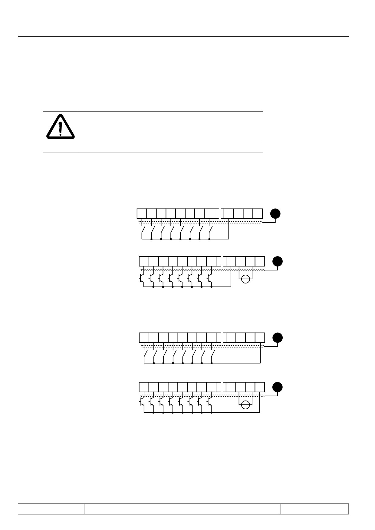
Digital inputs
Figure 3.1.3.a Digital inputs in PNP control (di.00 = 0)
24V
24V
I1
I2
I3
I4
F R STRST
GND
out
in
Internal supply
X2A
10
11
12
13
14
15
16
17
20
21
22
23
PE
Ri (digital inputs)= 2,1
kΩ
24V
24V
I1
I2
I3
I4
F R ST RST
GND
out
in
X2A
10
11
12
13
14
15
16
17
20
21
22
23
PE
External supply
+
Switching voltage for digital inputs = 13...30V DC ±0% smoothed
Figure 3.1.3.b Digital inputs in NPN control (di.00 = 1)
Internal supply
24V
24V
I1
I2
I3
I4
F R
ST RST
GND
out
in
X2A
10
11
12
13
14
15
16
17
20
21
22
23
PE
Ri (digital inputs)= 2,1kΩ
External supply
Page3.1 - 4
Control Units
3.1.4
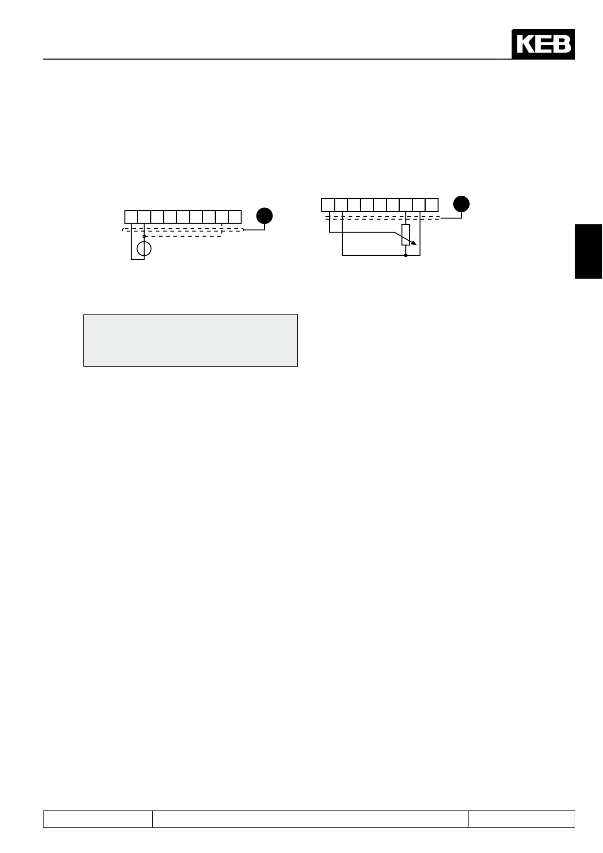
Analog inputs
Connect unused analog inputs with the analog mass, to prevent set value fluctuations!
External analog
Internal analog
setpoint setting
setpoint setting
Ri = 55 k
X2A
1
2
3
4
5
6
7
8
9
PE
X2A 1
2
3
4
5
6
7
8
9
PE
3
+
R = 3...10 k
0...±10 VDC
The inputs X2A.3 and X2A.4 can be programmed also as setpoint input and interconnected (see chapter 7.2).
Connect equipotential bonding conductor only,
if a potential difference of > 30 V exists bet-
ween the controls. The internal resistance is
reduced to 30 KΩ.
3.1.5
Voltage input / external power supply
The supply of the control circuit through an external voltage source keeps the control in operational condition
even if the power stage is switched off. To prevent undefined conditions at external power supply the basic
procedure is to first switch on the power supply and after that the inverter.
Page3.1 - 5
Control Units
Page3.1 - 6
Fundamentals
1.
Introduction
2.
Summary
3.
Hardware
4.
Operation
4.1
Fundamentals
4
Selection of Operating
5.
Mode
6.
Initial Start-up
7.
Functions
8.
Error Assistance
9.
Project Design
4.2
Password input
10. Networks
11. Parameter Overview
12. Annex
Page4.1 - 1
Fundamentals
4.1.1
Parameter, parameter groups, parameter sets
4.1 - 3
4.1.2
Selection of a parameter
4.1 - 4
4.1.3
Adjustment of parameter value
4.1 - 4
4.1.4
ENTER-parameter
4.1 - 5
4.1.5
Non-programmable parameters
4.1 - 5
4.1.6
Resetting of error messages
4.1 - 5
4.1.7
Resetting of peak values
4.1 - 5
4.1.8
Acknowledgement of status signals
4.1 - 5
Page4.1 - 2
Fundamentals
4. Operation
The following chapter describes the fundamentals of the software structure as well as the operating of the
unit.
4.1
Fundamentals
The control boards F5 include following operating modes:
Operating modes of the control board
Customer mode
Application mode
Drive mode
- is a list of parameters (CP
- all parameter groups (exep-
- with this special mode, the unit
parameters), freely defina-
tion: CP-parameter) and pa-
can be put into operation via
4
ble, which are necessary or
rameter sets can be selected
operator
important for the user
and, if necessary, changed
- with the exception of the con-
- supplied with a parameter
- usually it is activated only for
trol release no terminal wiring
list defined by KEB
the adaption to the applica-
is needed
tion
4.1.1
Parameter, parameter groups, parameter sets
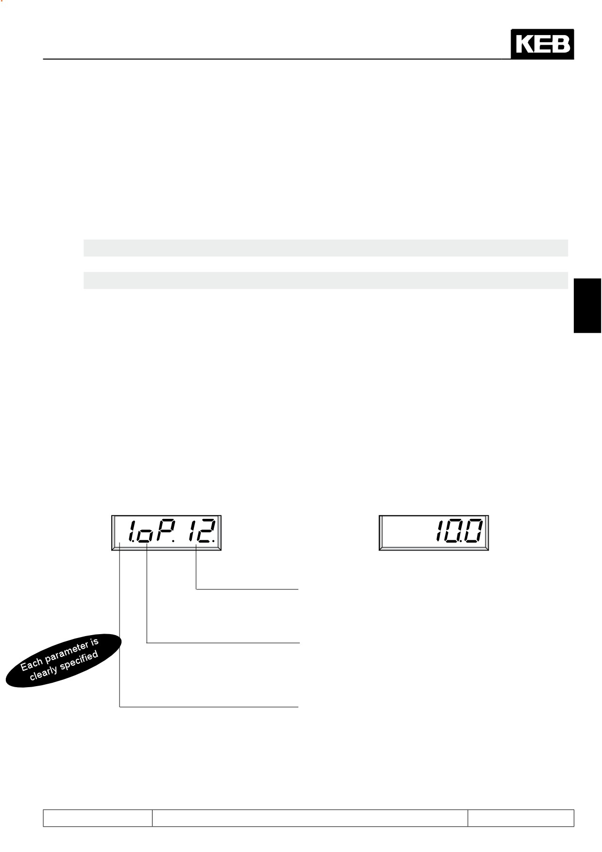
What are parameter, parameter groups und parameter sets?
Parameters are values changeable by the operator in a program, which have an influence on the program flow.
A parameter consists of:
Parameter designation
and
Parameter value
The parameter value displays the current settings
´The parameter number specifies the parameter within
a group.
To maintain a cleary-to-survey operation inspite of the
great number of parameters, we have combined function-
related parameters into parameter groups (e.g. all motor-
related parameters are combined in the drive(dr)-group).
8 parameter sets (0...7) exists to adjust several values for
one parameter. If the active values shall be displayed for
a running unit the digit is set to „A“. There is no digit for
non-programmable parameters.
Example:
A conveyor belt shall be used with 3 different speeds. A parameter set is programmed for each "speed" ...acceleration,
deceleration etc. can be adjusted individually.
Page4.1 - 3
Fundamentals
4.1.2
Selection of a parameter
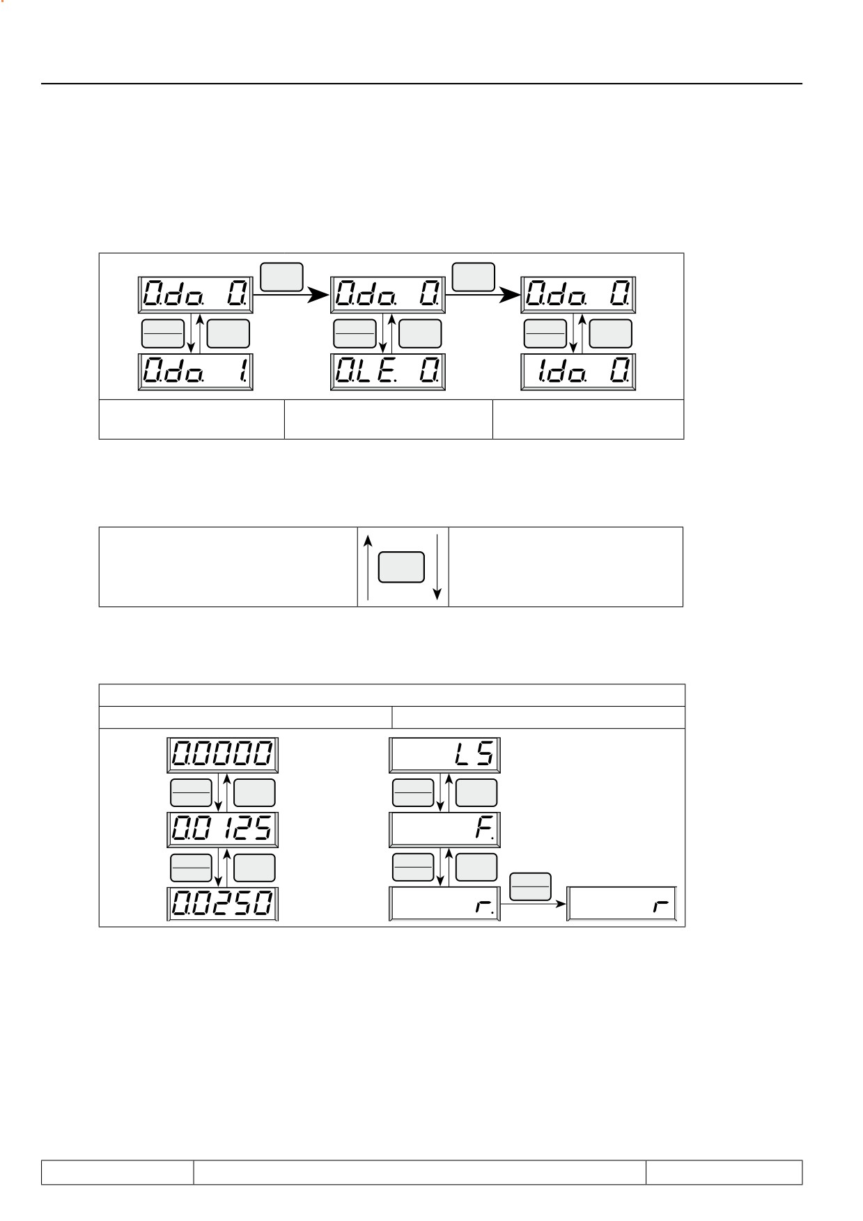
The blinking point indicates the changeable area. By pressing the ENTER-key the blinking point is shifted.
ENTER
ENTER
F/R
F/R
▲
STOP
▲
STOP
▲
STOP
START
▼
START
▼
START
▼
Parameter number
Parameter number
Parameter number
select
select
select
For non-programmable parameters (see 4.1.5)
a parameter set number is not displayed
FUNC
Change between parameter values
and parameter designation.
SPEED
4.1.3
Adjustment of parameter value
Changing of
standard-parameters
ENTER-parameters
-values are
- during changing a point is
immediately
indicates behind the last
▲
STOP
▲
STOP
accepted and
digit
START
▼
START
▼
stored non-
- the value is accepted and
volatile
stored non-volatile by
pressing ENTER
▲
STOP
▲
STOP
START
▼
START
▼
ENTER
F/R
Parameter values can be changed only, when the parameter set is not adjusted to "Active parameter
set" (A)! (see 4.1.6)
Page4.1 - 4
Fundamentals
4.1.4
ENTER-parameter
For some parameters it is not sensible that the selected values become active immediately. For that reason
they are called ENTER-parameters, they do not become active until the ENTER-key is pressed.
Example: At digital setting of rotation direction the rotation reverse (r) shall be selected from standstill (LS). As
seen above it must be switched at this in forward (F) direction of rotation (F). The drive shall start only if the
direction of rotation reverse is selected and confirmed with ENTER.
4.1.5
Non-programmable parameters
Certain parameters are not programmable, as their value must be the same in all sets (e.g. bus address or
baud rate). For an easy identification of these parameters the parameter set number is missing in the para-
meter identification. For all non-programmable parameters the same value is valid independent of the
selected parameter set!
4
4.1.6
Resetting of error messages
If a malfunction occurs during operation, the actual display is overwritten by a blinking error message. The
error message can be deleted by pressing the ENTER key, so the initial value is displayed again.
ATTENTION! The resetting of the error message with ENTER is no error reset, i.e. the error status in the in-
verter is not reset. Thus is possible to correct adjustments before the error reset. An error reset is only possible
by the reset terminal or control release.
4.1.7
Resetting of peak values
To permit conclusions on the operational performance of the drive, parameters are provided that indicate the
peak values. Peak value means that the highest measured value is stored for the ON-time of the inverter
(slave pointer principle). The peak value is cancelled by ▲ or ▼ and the actual measured value is shown in
the display.
4.1.8
Acknowledgement of status signals
To monitor the correct execution of an action some parameters send a status signal. For example, after co-
pying a set the display shows "PASS" to indicate that the action was carried out without errors. These status
signals must be acknowledged with ENTER.
Page4.1 - 5
Fundamentals
Page4.1 - 6
Password Structure
1.
Introduction
2.
Summary
3.
Hardware
4.1
Fundamentals
4.
Operation
4
Selection of Operating
5.
Mode
6.
Initial Start-up
7.
Functions
8.
Error Assistance
9.
Project Design
4.2
Password structure
10. Networks
11. Parameter Overview
12. Annex
Page4.2 - 1
Password Structure
4.2.1
Password levels
4.2 - 3
4.2.2
Passwords
4.2 - 4
4.2.3
Changing of password level
4.2 - 5
Page4.2 - 2
Password Structure
4.2
Password structure
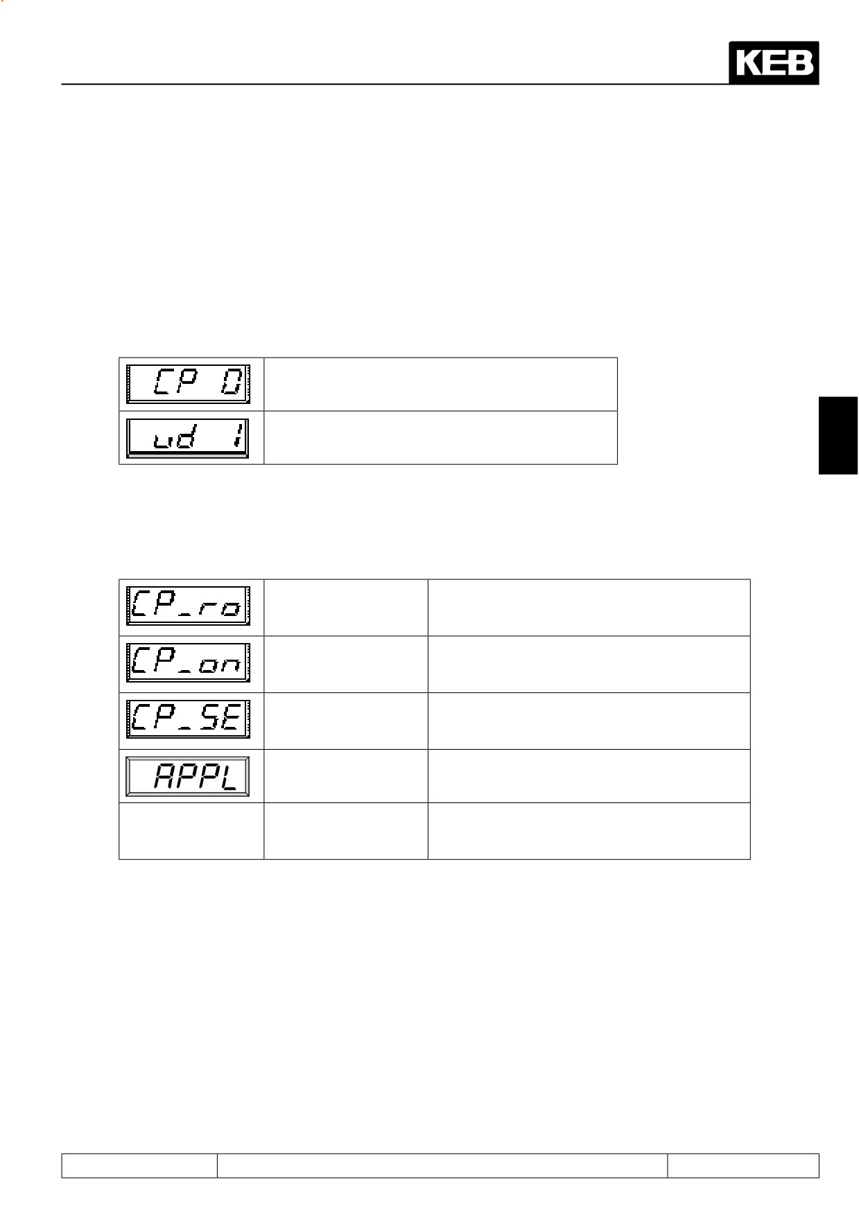
The KEB COMBIVERT is provided with extensive password protection. The different passwords are used to
- change the operating mode
- set a write protection
- activate the service mode
- switch to the Drive mode
Depending on the actual operating mode the password can be entered in the following parameters:
when the CP mode is active
when the application mode is active
4
4.2.1
Password levels
The parameter value of the above parameters shows the actual password level. Following indications are
possible:
Only the customer parameter group is visible,
CP - read only
exept for CP. 0 all parameters are in the read-only
status (see chapter 4.3).
Only the customer parameter group is visible. All
CP - on
parameters can be changed.
Like CP-on, but the parameter identification is
CP service
indicated according to the original parameter (see
chapter 4.3)
All application parameters are visible and can be
Application
changed. The CP-parameters are not visible.
The Drive-Mode is a special operating mode, here
Drive mode
the unit can be put into operation via the operator
(see chapter 4.4).
Page4.2 - 3
Password Structure
4.2.2
Passwords
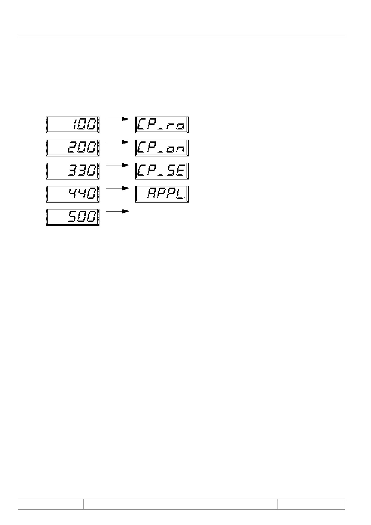
By selecting one of the following passwords you can switch to the respective password level:
Passwords
Password level
Drive mode
To finish the Drive-Mode press ENTER + FUNCT key for approx. 3 sec.
Page4.2 - 4
Password Structure
4.2.3
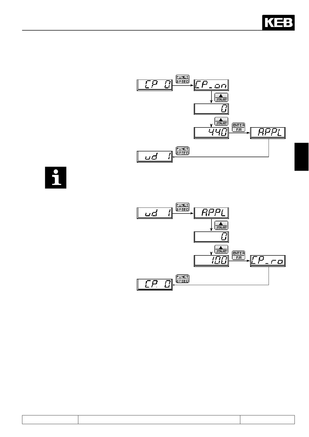
Changing of password level
Example 1:
Switching from CP mode
to the application mode
4
With the exception of the
service password all entered
password levels are gene-
rally stored non volatile!
Example 1:
Switching from applica-
tion mode to the CP read
only mode
Page4.2 - 5
Password Structure
Page4.2 - 6
Selection of Operating Mode
1.
Introduction
2.
Summary
3.
Hardware
4.
Operation
Selection of Operating
5.
5.1
Selection of operating mode
5
Mode
6.
Initial Start-up
7.
Functions
8.
Error Assistance
9.
Project Design
10. Networks
11. Parameter Overview
12. Annex
Page5.1 - 1
Selection of Operating Mode
Page5.1 - 2

Selection of Operating Mode
5. Selection of Operating Mode
This instruction manual is valid for the following software versions:
Software
Control type
Description
type
(adjustment ud.02)
4: F5-M / 4000rpm
5: F5-M / 8000rpm
6: F5-M / 16000rpm
Standard software for the operation:
7: F5-M / 500rpm
F5A V4.00
- of asynchronous motors with vector control
8: F5-S / 4000rpm
- of asynchronous motors with V/F characteristic control
9: F5-S / 8000rpm
- of synchronous motors with vector control
10: F5-S / 16000rpm
11: F5-S / 500rpm
4: F5-M / 4000rpm
5: F5-M / 8000rpm
Software for motors with a maximum speed upto 128000 rpm (high-frequency ap-
6: F5-M / 16000rpm
plications)
7: F5-M / 32000rpm
5
12: F5-M / 64000rpm
corresponding to standard software F5A-M V4.00, except:
• Control type 7 or 11 is for a maximum speed of 32000 rpm instead of 500 rpm
13: F5-M / 128000rpm
F5A V4.01
• additional control types 12 / 13 or 14 / 15 for motors with a maximum speed of 64000
8: F5-S / 4000rpm
rpm or 128000 rpm.
9: F5-S / 8000rpm
(Attention: With output frequencies > 800Hz or if the ratio of output frequency to rated
10: F5-S / 16000rpm
frequency is smaller than 1:10, please contact KEB regarding to the application.)
11: F5-S / 32000rpm
14: F5-S / 64000rpm
15: F5-S / 128000rpm
4: F5-M / 4000rpm
Software for the speed-controlled operation of asynchronous motors without
speed feedback.
5: F5-M / 8000rpm
F5H V2.00
The measured speed is replaced by an estimated speed actual value, which is formed by
6: F5-M / 16000rpm
means of a mathematical model of the asynchronous motor.
7: F5-M / 500rpm
- Also operation with speed feedback possible.
4: F5-M / 4000rpm
Software for the speed controlled operation of asynchronous motors without
5: F5-M / 8000rpm
speed feedback with a maximum speed upto 128000 rpm
6: F5-M / 16000rpm
- Control type 7 is for a maximum speed of 32000 rpm instead of 500 rpm
F5H V2.01
7: F5-M / 32000rpm
- additional control types 12 and 13
12: F5-M / 64000rpm
(Attention: restrictions see high-frequency software F5A V4.01)
13: F5-M / 128000rpm
8: F5-S / 4000rpm
Software for the speed-controlled operation of synchronous motors without speed
feedback.
9: F5-S / 8000rpm
F5E V2.10
The measured speed is replaced by an estimated speed actual value, which is formed by
10: F5-S / 16000rpm
means of a mathematical model of the synchronous motor.
11: F5-S / 500rpm
- Also operation with speed feedback possible
8: F5-S / 4000rpm
Software for the speed controlled operation of synchronous motors without speed
9: F5-S / 8000rpm
feedback with a maximum speed upto 128000 rpm
10: F5-S / 16000rpm
- Control type 11 is for a maximum speed of 32000 rpm instead of 500 rpm
F5E V2.11
11: F5-S / 32000rpm
- additional control types 14 and 15
14: F5-S / 64000rpm
(Attention: restrictions see high-frequency software F5A V4.01)
15: F5-S / 128000rpm
Page5.1 - 3

Selection of Operating Mode
This operating instruction is not valid for the G mode (V/F characteristics open loop mode, because the display
is scaled in Hz, not in rpm). I.e. this instruction is not valid for controller types, which selects the G-mode (F5-G
/ xxxHz).
Attention:
If a download list is downloaded to an inverter with another controller type, or if the COMBIVIS Config-File is
used for another controller type parameters (e.g. set speed, speed limits, etc..) are not correctly displayed.
COMBIVIS recognizes the use of not suitable lists and selects autmatically the right Config file. Unintended
settings and wrong displays can occur if the warning messages are ignored.
The standardisation of some parameters is depending on the speed range of the control type.
Stan-
Speed range
Resolution
Parameter
dard
500...32000
1 rpm
1
64000
2 rpm
SY.52, SY.53
128000
4 rpm
500
1 Nm
2
dr.27, dr.33, dr.40, dr.42, dr.44, dr.46
4000...128000
0,1 Nm
dr.01, dr.17, dr.18, dr.24, dr.39, dr.41, dr.43, dr.45, dr.47
500
0,125 rpm
CS.11, CS.12
3
4000...64000
1 rpm
Ec.25
128000
2 rpm
nn.02, nn.03
dS.19
Sy.45
ru.01, ru.02, ru.06, ru.07, ru.09, ru.10, ru.63, ru.79, ru.85, ru.86,
500
0,015625 rpm
ru.89
4000
0,125 rpm
op.03, op.06, op.07, op.10, op.11, op.14, op.15, op.21, op.22,
8000
0,5 rpm
op.23, op.40, op.41, op.64, op.65, op.66, op.67, op.68
4
16000
1 rpm
Pn.32, Pn.37, Pn.41, Pn.48
32000
2 rpm
dS.21
64000
4 rpm
LE.16
128000
8 rpm
cs.04
PS.08, PS.09, PS.21, PS.22, PS.25
nn.08
500
0,0015625 Hz
4000
0,0125 Hz
8000
0,05 Hz
ru.03
5
16000
0,1 Hz
uF.00, uF.02
32000
0,2 Hz
64000
0,4 Hz
128000
0,8 Hz
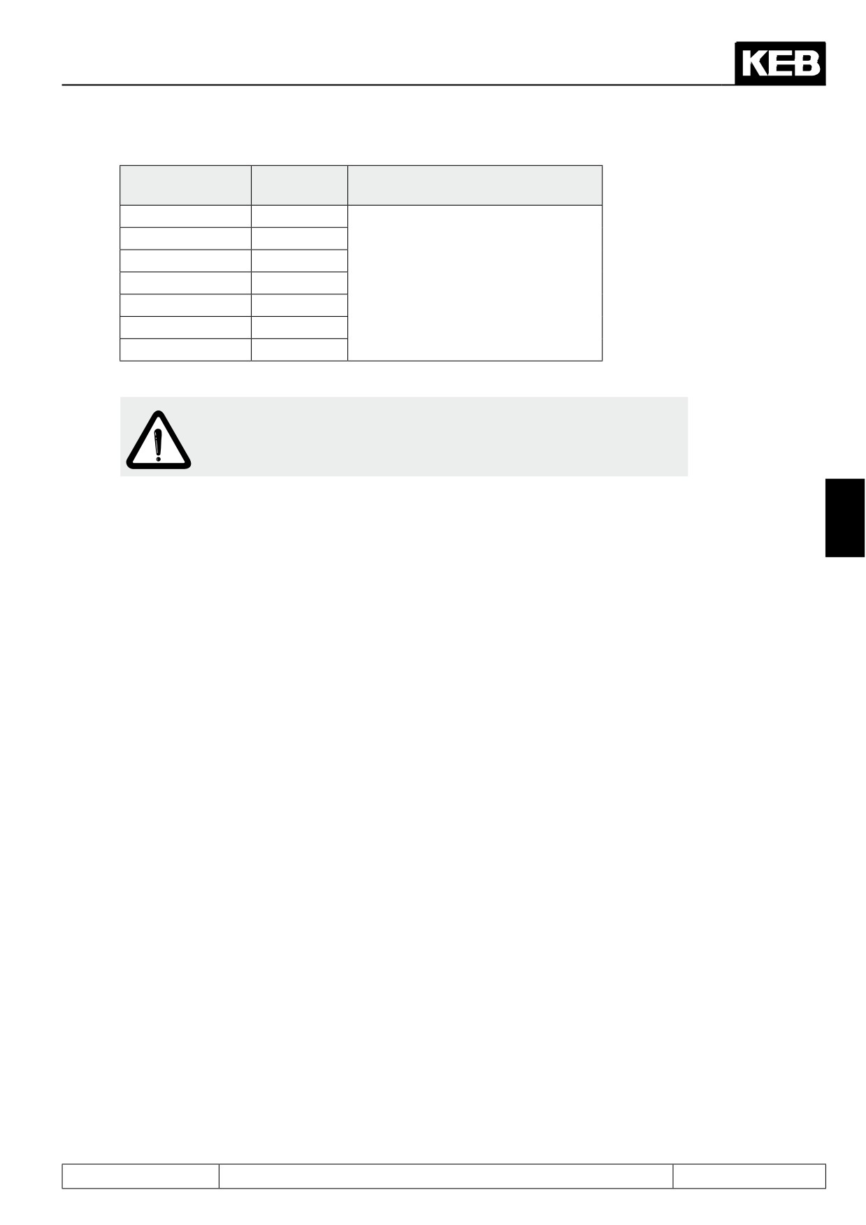
Some parameters (ramp adjustments) have reference values, which are depending on the selected speed
range (500, 4000, 8000, 16000, 32000, 64000, 128000 rpm.
Page5.1 - 4
Selection of Operating Mode
Speed range
Reference
Parameter
value
500
125 rpm
4000
1000 rpm
8000
2000 rpm
Pn.21, Pn.60
OP.28 .. 31, OP.46 - 48
16000
4000 rpm
dr.49
32000
8000 rpm
dS.22
64000
16000 rpm
128000
32000 rpm
Attention:
Unless otherwise noted, the description of individual parameter ad-
justments presets the speed range of 4000 rpm (ud.02 = 4 or 8).
Chapters 7.5 to 7.10 are not valid for all operating modes.
5
Which chapters are valid is dependent on the software type, control type and the selection in cS.00 and cS.
Page5.1 - 5