KEB COMBIVERT F5-A,-E,-H 4.0. APPLICATION MANUAL (2008) - page 1
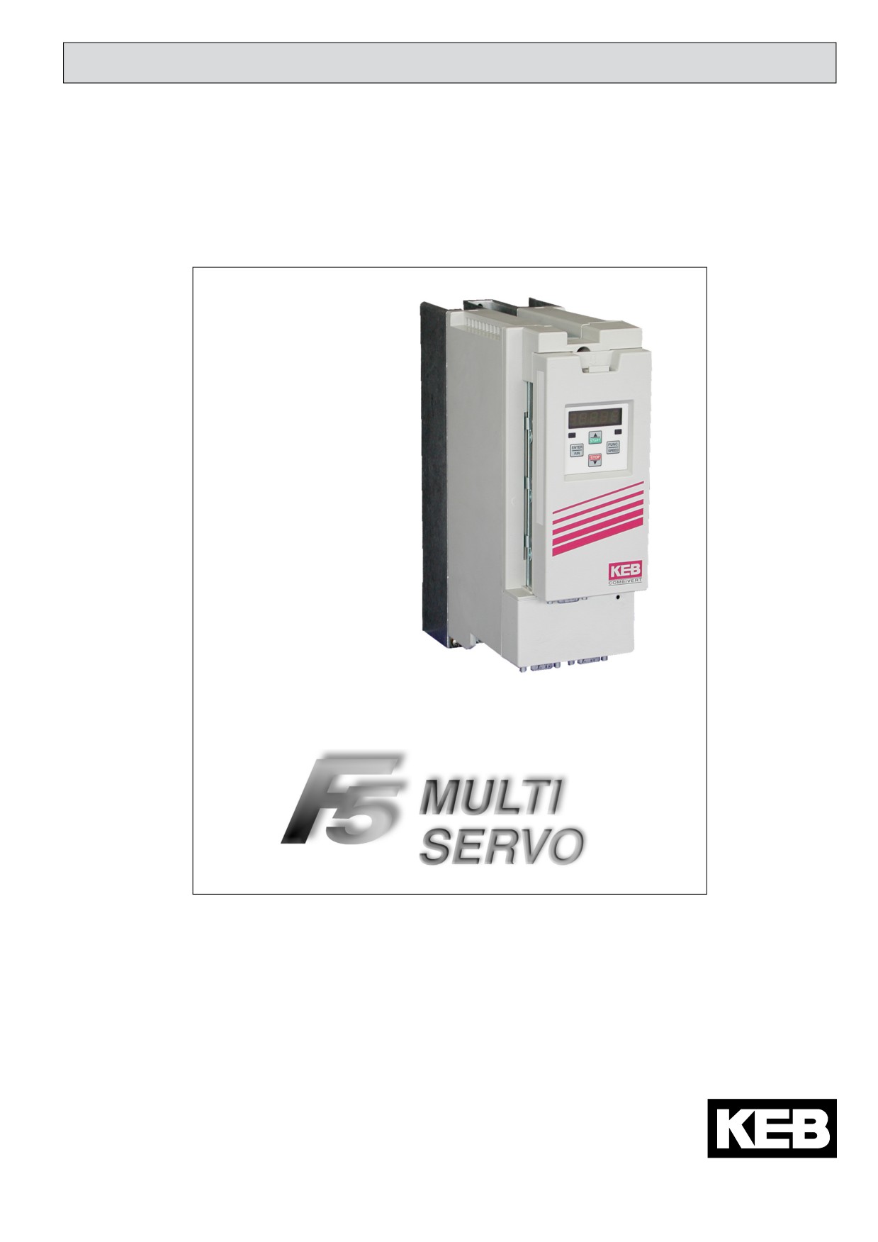
APPLICATION MANUAL
KEB COMBIVERT
F5-A,-E,-H 4.0
Art.Nr.: 00.F5.AEA-K400
Stand 08/2008
Table of Contents
1.
Introduction
Table of contents
1
2.
Summary
Notes and use conditions of the KEB COMBIVERT.
3.
Hardware
Description of the controls.
The basic operation of the KEB COMBIVERT like password input, parameter
4.
Operation
and set selection.
Selection of Operating
5.
Operating modes of the KEB COMBIVERT
Mode
Gives support with regard to the initial start-up and shows possibilities and
6.
Start-up
techniques for the optimization of the drive.
To make the programming easier all inverter functions and the parameters
7.
Functions
belonging to it are comprised in this chapter.
Avoidance of errors, evaluation of error messages and elimination of the
8.
Error Assistance
causes.
9.
Project Design
Serves for support of the drive design.
Survey of the possible interconnection of the KEB COMBIVERT in existing
10. Networks
networks.
A list of all parameters classified according to parameter groups. The para-
11. Parameter Overview
meter description comprises adresses, value ranges and references with
regard to the functions for which they are used.
12. Annex
Keyword index
Page 1.1 - 3
Table of Contents
1.
Table of Contents
1.1- 5
1.
Introduction
1.1 - 3
1
2.
Summary
2.1 - 3
2.1
Product description
2.1 - 3
2.1.1
Features of KEB COMBIVERT
2.1 - 3
2.1.2
Function principle
2.1 - 3
2.1.3
Application as directed
2.1 - 4
2.1.4
Type code
2.1 - 5
3.
Hardware
3.1 - 3
3.1
Control units
3.1 - 3
3.1.1
Terminal strip X2A
3.1 - 3
3.1.2
Connection of the control
3.1 - 4
3.1.3
Digital inputs
3.1 - 4
3.1.4
Analog inputs
3.1 - 5
3.1.5
Voltage input / external power supply
3.1 - 5
4.
Operation
4.1 - 3
4.1
Fundamentals
4.1 - 3
4.1.1
Parameter, parameter groups, parameter sets
4.1 - 3
4.1.2
Selection of a parameter
4.1 - 4
4.1.3
Adjustment of parameter value
4.1 - 4
4.1.4
ENTER-parameter
4.1 - 5
4.1.5
Non-programmable parameters
4.1 - 5
4.1.6
Resetting of error messages
4.1 - 5
4.1.7
Resetting of peak values
4.1 - 5
4.1.8
Acknowledgement of status signals
4.1 - 5
4.2
Password structure
4.2 - 3
4.2.1
Password levels
4.2 - 3
4.2.2
Passwords
4.2 - 4
4.2.3
Changing of password level
4.2 - 5
5.
Selection of Operating Mode
5.1 - 3
6.
Start-up
6.1 - 3
6.1
Preparatory measures
6.1 - 3
6.1.1
After unpacking the goods
6.1 - 3
6.1.2
Installation and connection
6.1 - 3
6.1.3
Checklist prior to start-up
6.1 - 4
6.2
Initial start-up
6.2 - 3
6.2.1
Start-up of an asynchronous motor
6.2 - 3
6.2.1.1
V/F characteristic operation
6.2 - 4
6.2.1.2
Vector controlled operation with encoder feedback without motor model
6.2 - 6
6.2.1.3
Vector controlled operation with encoder feedback with motor model
6.2 - 9
Page 1.1 - 5
Table of Contents
6.2.1.4
Start-up F5H-M (ASCL/ vector controlled without encoder feedback
with motor model)
6.2 - 12
6.2.2
Start-up of a synchronous motor
6.2 - 16
6.2.2.1
Start-up F5A-S
6.2 - 16
6.2.2.2
Start-up F5E-S (SCL)
6.2 - 18
7.
Functions
7.1 - 3
7.1
Operating and appliance date
7.1 - 3
7.1.1
Overview of the ru-parameters
7.1 - 3
7.1.2
Overview of the In-parameters
7.1 - 4
7.1.3
Overview of the Sy-parameters
7.1 - 4
7.1.4
Explanation to parameter description
7.1 - 5
7.1.5
Description of the ru-parameters
7.1 - 6
7.1.6
Description of the In-parameters
7.1 - 23
7.1.7
Description of the Sy (system) - parameters
7.1 - 27
7.2
Analog in- and outputs I
7.2 - 3
7.2.1
Summary description analog inputs
7.2 - 3
7.2.2
Interface selection
7.2 - 4
7.2.2.1
AN1 / AN2 (An.00, An.10)
7.2 - 4
7.2.2.2
AN3 (An.20)
7.2 - 5
7.2.3
Noise filter (An.01, An.11, An.21)
7.2 - 5
7.2.4
Save mode (An.02, An.12, An.22)
7.2 - 5
7.2.4.1
Input selection (An.03, An.13, An.23)
7.2 - 6
7.2.5
Zero clamp (An.04, An.14, An.24)
7.2 - 7
7.2.6
Gain of the input characteristics (An.05...07, An.15...17, An.25...27)
7.2 - 8
7.2.7
Lower and upper limit (An.08, An.09, An.18, An.19, An.28, An.29)
7.2 - 10
7.2.8
Selection REF input / AUX-function (An.30)
7.2 - 11
7.2.9
Brief description analog outputs
7.2 - 12
7.2.10
Output signals
7.2 - 13
7.2.11
Analog output / display (ru.33...34 / ru.35...36)
7.2 - 13
7.2.12
ANOUT 1/ -2/-3/-4/ function (An.31 / An.36 / An.41, An.47)
7.2 - 14
7.2.13
Gain of Output Characteristic (An.33...35 / An.38...40 /
An.43...45 / An.49...51)
7.2 - 15
7.2.14
ANOUT 1...4 digitale setting (An.32 / 37 / 42 / 48)
7.2 - 16
7.3
Digital in- and outputs
7.3 - 3
7.3.1
Summary description digital inputs
7.3 - 3
7.3.2
Input signals PNP / NPN selection (di.00)
7.3 - 4
7.3.3
Setting of digital inputs by software (di.01, di.02)
7.3 - 5
7.3.4
Input terminal state (ru.21), internal input state (ru.22)
7.3 - 6
7.3.5
Digital noise filter (di.03), fast dig. noise filter (di.23)
7.3 - 6
7.3.6
Input logic (di.04)
7.3 - 6
7.3.7
Input trigger (di.05)
7.3 - 6
7.3.8
Strobe-dependent inputs (di.06, di.07, di.08)
7.3 - 7
7.3.10
Error reset / input selection and edge evaluation (di.09 / di.10)
7.3 - 8
7.3.11
Assignment of the inputs
7.3 - 9
7.3.12
Software ST and locking of the control release
7.3 - 12
7.3.13
Deactivation of the digital control release
7.3 - 12
Page 1.1 - 6
Table of Contents
7.3.14
Summary description digital outputs
7.3 - 13
7.3.15
Output signals / hardware
7.3 - 14
1
7.3.16
Output filter (do.43, do.44)
7.3 - 14
7.3.17
Switching conditions (do.00...do.07)
7.3 - 15
7.3.18
Inverting of switching conditions for flags 0...7 (do.08...do.15)
7.3 - 20
7.3.19
Selection of switching conditions for flags
0...7 (do.16...do.23)
7.3 - 20
7.3.20
Linking the switching conditions for flags (do.24)
7.3 - 20
7.3.21
Inverting of flags (do.25...do.32)
7.3 - 21
7.3.22
Selection of flags (do.33...do.40)
7.3 - 21
7.3.23
Linking the flags(do.41)
7.3 - 22
7.3.24
Output terminal state (ru.25) and digital output state (ru.80)
7.3 - 23
7.3.25
Hardware output allocation (do.51)
7.3 - 23
7.3.26
Programming example
7.3 - 24
7.4
Setpoint-, rotation- and ramp adjustment
7.4 - 3
7.4.1
Summary description
7.4 - 3
7.4.2
Reference source oP.00
7.4 - 4
7.4.3
Rotation source oP.01
7.4 - 7
7.4.4
Fixed frequencies (oP.18...23)
7.4 - 11
7.4.5
Setpoint limits
7.4 - 13
7.4.6
Setpoint calculation
7.4 - 15
7.4.7
Ramp generator
7.4 - 16
7.4.8
acc dec mode
7.4 - 20
7.4.8.1
Ramp with constant ascent
7.4 - 20
7.4.8.2
Ramp with constant time
7.4 - 20
7.4.8.3
Ogive run
7.4 - 23
7.5
Motor data and controller adjustments of the asynchronous motor
7.5 - 3
7.5.1
Open loop operation (V/F characteristic)
7.5 - 4
7.5.1.1
Rated frequency (uF.00), boost (uF.01) and delta boost (uF.04 / uF.05)
7.5 - 4
7.5.1.2
Maximum voltage mode (uF.10)
7.5 - 5
7.5.1.3
Additional rated point (uF.02/uF.03)
7.5 - 5
7.5.1.4
Voltage stabilization (uF.09)
7.5 - 6
7.5.1.5
Carrier frequency (uF.11)
7.5 - 7
7.5.1.6
Energy saving mode (uF.06...08)
7.5 - 7
7.5.1.7
SMM (sensorless motor management)
7.5 - 8
7.5.2
Vector controlled operation
7.5 - 12
7.5.2.1
Initial settings
7.5 - 12
7.5.2.2
Vector controlled operation without motor model
7.5 - 14
7.5.2.3
Vector controlled operation with motor model (with encoder feedback)
7.5 - 16
7.5.2.4
Vector control without speed feedback (ASCL)
7.5 - 23
7.5.2.5
Special function: Rotor adaption
7.5 - 28
7.5.3
Block diagram
7.5 - 29
7.6
Adjustments of the synchronous motor
7.6 - 3
7.6.1
Initial settings
7.6 - 3
7.6.1.1
Motor name plate
7.6 - 3
7.6.1.2
Controller configuration
7.6 - 4
7.6.1.3
Actual value source
7.6 - 4
7.6.1.4
Load motor dependent parameter
7.6 - 5
7.6.2
Speed-controlled operation with encoder feedback
7.6 - 6
7.6.2.1
Controller Structure
7.6 - 6
Page 1.1 - 7
Table of Contents
7.6.2.2
Absolute position (encoder 1)
7.6 - 6
7.6.2.3
Absolute encoder
7.6 - 7
7.6.3
Speed-controlled operation without encoder feedback (SCL)
7.6 - 8
7.6.3.1
General
7.6 - 8
7.6.3.2
Initial settings for sensorless operation
7.6 - 8
7.6.3.3
Identification of the motor data
7.6 - 8
7.6.3.4
Standstill and starting phase
7.6 - 12
7.6.3.5
Low speed
7.6 - 15
7.6.3.6
Motor model
7.6 - 16
7.6.3.7
Operation with sine-wave filter
7.6 - 18
7.6.4
Block diagram
7.6 - 19
7.7
Speed control
7.7 - 3
7.7.1.
Speed controller parameters
7.7 - 3
7.7.1.1
Basic settings
7.7 - 3
7.7.1.2
Automatically adjustment of the speed controller (only at the operation
with motor model)
7.7 - 3
7.7.1.3
Operating condition dependent control parameters
7.7 - 4
7.7.2.
Determination of the mass moment of inertia
7.7 - 5
7.7.3.
PT1 output filter
7.7 - 6
7.7.4.
Acceleration dependent pre-control
7.7 - 6
7.7.4.1
Precontrol reach-through / smoothing
7.7 - 7
7.7.4.2
Setpoint smoothening
7.7 - 7
7.8
Torque display and -limiting
7.8 - 3
7.8.1
Maximum voltage controller, voltage limit
7.8 - 3
7.8.2
Physical torque limits ASM
7.8 - 4
7.8.2.1
Torque limits in the base speed range
7.8 - 4
7.8.2.2
Torque limits in the field weakening range
7.8 - 4
7.8.3
Physical torque limits DSM
7.8 - 6
7.8.3.1
Torque limits in the base speed range (dr.27, dr.15)
7.8 - 6
7.8.3.2
Torque limits in the field weakening range
7.8 - 6
7.8.4
Setting of the application-dependent torque limits
7.8 - 13
7.8.5
Display of the actual torque values and limits
7.8 - 14
7.8.6
Display of the torque-related motor workload (ru.90)
7.8 - 14
7.8.6.1
Mode 1: "Reference torque" Le 27 = 0
7.8 - 14
7.8.6.2
Mode 2: "Reference torque" Le 27 unequal 0
7.8 - 15
7.9
Torque control
7.9 - 3
7.9.1.
Torque reference source
7.9 - 3
7.9.2.
Rate of change torque reference
7.9 - 3
7.9.3.
Speed calculation
7.9 - 4
7.9.4.
Control mode
7.9 - 4
7.9.4.1
Mode 1: torque-controlled operation with emergency switching to speed control.7.9 - 4
7.9.4.2
Mode 2: torque-controlled operation with superimposed speed control
7.9 - 5
7.10
Current control, -limiting and switching frequencies
7.10 - 3
7.10.1
Current control
7.10 - 3
7.10.2.
Current limit
7.10 - 4
7.10.3
Switching frequencies and derating
7.10 - 5
7.10.3.1
Switching frequency (uF.11, In.03, In.04, ru.45)
7.10 - 5
7.11
Speed measurement
7.11 - 3
7.11.1
Designs
7.11 - 3
Page 1.1 - 8
Table of Contents
7.11.2
Encoder interface channel 1 (X3A)
7.11 - 4
7.11.2.1
TTL incremental encoder input (standard at F5-M)
7.11 - 4
1
7.11.3
Encoder interface channel 2 (X3B)
7.11 - 6
7.11.3.1
Incremental encoder input
7.11 - 6
7.11.3.2
Incremental encoder output
7.11 - 7
7.11.4
Voltage supply of encoder
7.11 - 8
7.11.5
Selection of encoder
7.11 - 8
7.11.5.1
Cable length
7.11 - 9
7.11.5.2
Signal sequence / level
7.11 - 10
7.11.6
Encoder identifier
7.11 - 11
7.11.7
Basic settings
7.11 - 12
7.11.8
Gear factor
7.11 - 14
7.11.8.1
Definition
7.11 - 14
7.11.8.2
Gear factor / analog setting
7.11 - 16
7.11.8.3
Gear factor / set-programming
7.11 - 16
7.11.9
Operation mode output
7.11 - 17
7.11.10
Absolute position encoder 1 / 2 (Ec.02 / Ec.12) (only for F5-S)
7.11 - 18
7.11.11
System offset (Ec.33 / Ec.34)
7.11 - 18
7.11.12
Further parameter / encoder
7.11 - 18
7.11.12.1
SSI encoder at channel 1
7.11 - 19
7.11.12.2
SSI encoder at channel 2
7.11 - 19
7.11.12.3
SSI position normalization channel 1 u. 2 (Ec.42)
7.11 - 20
7.11.12.4
Tachometer at channel 2
7.11 - 21
7.11.12.5
Evaluation intelligent interface
7.11 - 21
7.11.12.6
Encoder 1 over transmission (Ec.39)
7.11 - 28
7.12
Positioning and synchronous control
7.12 - 4
7.12.1
Limit switch
7.12 - 4
7.12.1.1
Hardware limit switch
7.12 - 4
7.12.1.2
Software limit switch
7.12 - 4
7.12.2
Approach the reference point
7.12 - 5
7.12.2.1
Approach to reference point / modes
7.12 - 6
7.12.2.2
Approach to reference point / stopping point
7.12 - 8
7.12.2.3
Approach to reference point / stop at zero signal
7.12 - 8
7.12.2.4
Approach to reference point / no driving free
7.12 - 9
7.12.2.5
Approach to reference point / limit switch
7.12 - 9
7.12.2.6
Reference point / manual setting
7.12 - 11
7.12.2.7
Reference point / valid position
7.12 - 11
7.12.2.8
Approach to reference point / stop at index 0
7.12 - 12
7.12.3
Synchronous mode
7.12 - 13
7.12.3.1
Synchronous mode / principle
7.12 - 13
7.12.3.2
Synchronous mode / premise
7.12 - 14
7.12.3.4
Synchronous mode / position normalisation
7.12 - 16
7.12.3.5
Synchronous mode / selection of operating mode
7.12 - 17
7.12.3.6
Synchronous mode / activation and synchronization
7.12 - 18
7.12.3.7
Gear factor
7.12 - 23
7.12.3.8
Angular correction
7.12 - 24
7.12.3.9
Angular reset
7.12 - 25
7.12.4
Posi mode
7.12 - 26
7.12.4.1
Selection of operating mode
7.12 - 26
7.12.4.2
Posi mode / principle
7.12 - 26
7.12.4.3
Posi mode / premise
7.12 - 28
7.12.4.4
Position normalisation
7.12 - 29
Page 1.1 - 9
Table of Contents
7.12.4.5
Posi mode / actual position
7.12 - 33
7.12.4.6
Posi mode / set and target position
7.12 - 33
7.12.4.7
Posi mode / single positioning
7.12 - 34
7.12.4.8
Posi mode / sequential positioning
7.12 - 37
7.12.4.9
Posi mode / Positioning with set changeover
7.12 - 50
7.12.4.10
Posi mode / rotary table
7.12 - 50
7.12.4.11
Posi mode / defined stop
7.12 - 56
7.12.4.12
Posi mode / remaining distance positioning
7.12 - 57
7.12.4.13
Posi mode / flying referencing with correction
7.12 - 58
7.12.4.14
Posi mode / start positioning
7.12 - 63
7.12.4.15
Posi mode / not reachable positions
7.12 - 67
7.12.4.16
Posi mode / stop positioning
7.12 - 69
7.12.4.17
Analog position setting
7.12 - 70
7.12.4.18
Analog position output
7.12 - 70
7.12.4.19
Target window
7.12 - 71
7.12.4.20
Position scan
7.12 - 71
7.12.4.21
Teach function
7.12 - 72
7.12.4.22
Functions and displays for the positioning mode
7.12 - 73
7.12.5
Contouring control mode
7.12 - 75
7.12.5.1
Contouring control mode / premises
7.12 - 75
7.12.5.2
Contouring control mode / settings
7.12 - 76
7.12.5.3
Contouring control mode / write / read data
7.12 - 77
7.12.5.4
Contouring control mode / speed precontrol
7.12 - 77
7.12.5.5
Contouring control mode / watchdog
7.12 - 77
7.12.5.6
Contouring control mode / example
7.12 - 78
7.12.6
Position controller
7.12 - 80
7.13
Protective functions
7.13 - 3
7.13.1
Error and warning messages
7.13 - 3
7.13.1.1
Undervoltage
7.13 - 4
7.13.1.2
Overvoltage
7.13 - 4
7.13.1.3
Overcurrent
7.13 - 4
7.13.1.4
Overload
7.13 - 4
7.13.1.5
Inverter over temperature
7.13 - 5
7.13.1.6
External fault
7.13 - 5
7.13.1.7
Bus error
7.13 - 5
7.13.1.8
Limit switch error
7.13 - 6
7.13.1.9
Motor protection with temperature sensor
7.13 - 7
7.13.1.10
Software motor protection
7.13 - 7
7.13.1.11
Set selection error
7.13 - 7
7.13.1.12
Encoder interface / encoder error
7.13 - 8
7.13.1.13
Speed limit exceeded
7.13 - 8
7.13.1.14
Speed controller limit reached
7.13 - 9
7.13.1.15
Maximum acceleration exceeded
7.13 - 9
7.13.1.16
General power circuit error
7.13 - 9
7.13.2
Response to malfunction messages
7.13 - 10
7.13.2.1
Selection of the response
7.13 - 10
7.13.2.2
Parametrisation of the abnormal stopping
7.13 - 12
7.13.3
Automatic restart
7.13 - 15
7.13.3.1
Undervoltage error (E.UP)
7.13 - 15
7.13.3.2
Overvoltage error (E.OP)
7.13 - 15
7.13.3.3
Overcurrent error (E.OC)
7.13 - 15
7.13.3.4
Malfunction messages and pre-warnings
7.13 - 16
7.13.4
Base block
7.13 - 16
7.13.5
Quick Stop
7.13 - 16
Page 1.1 - 10
Table of Contents
7.13.5.1
Quick stop in the V/F characteristic operation
7.13 - 17
7.13.5.2
Quick stop at closed-loop systems
7.13 - 18
7.13.5.3
Time monitoring abnormal stopping
7.13 - 19
1
7.13.5.4
Abnormal stopping via control word
7.13 - 19
7.13.6
Speed search
7.13 - 19
7.13.6.1
Speed search in the open loop operation
7.13 - 20
7.13.6.2
Speed search at asynchronous motors in the closed-loop operation
with encoder
7.13 - 20
7.13.6.3
Speed search at asynchronous motor in the closed-loop operation
without encoder (ASCL)
7.13 - 20
7.13.7
LAD-stop
7.13 - 20
7.13.7.1
Current-dependent ramp stop
7.13 - 21
7.13.7.2
DC link voltage-dependent ramp stop
7.13 - 21
7.13.7.3
Ramp stop dependent on a digital input
7.13 - 21
7.13.8
Current limit constant run (stall function)
7.13 - 22
7.13.9
Motor Protection Mode
7.13 - 25
7.13.10 Power-Off function
7.13 - 29
7.13.11 GTR7-Control
7.13 - 35
7.13.11.1
Activation via digital input
7.13 - 35
7.13.11.2
Adjustment of the activation threshold
7.13 - 35
7.13.11.3
Activation conditions
7.13 - 36
7.13.12 Special functions
7.13 - 36
7.14
Parameter sets
7.14 - 3
7.14.1
Non-programmable parameters
7.14 - 3
7.14.2
Security parameters
7.14 - 3
7.14.3
System Parameters
7.14 - 3
7.14.4
Indirect and direct set-addressing
7.14 - 4
7.14.5
Copying of parameter sets via keyboard (Fr.01)
7.14 - 4
7.14.6
Copying of parameter sets via bus (Fr.01, Fr.09)
7.14 - 5
7.14.7
Parameter set selection
7.14 - 8
7.14.8
Locking of parameter sets
7.14 - 12
7.14.9
Parameter set ON/OFF delay (Fr.05, Fr.06)
7.14 - 13
7.15
Special functions
7.15 - 3
7.15.1
DC-braking
7.15 - 3
7.15.1.1
V/F characteristic control
7.15 - 5
7.15.1.2
Speed-controlled operation without feedback (ASCL)
7.15 - 5
7.15.2
Energy Saving Function
7.15 - 5
7.15.3
Motorpoti Function
7.15 - 6
7.15.4
Timer and Counter
7.15 - 9
7.15.5
Brake Control
7.15 - 12
7.15.5.1
Brake control mode
7.15 - 13
7.15.5.2
Monitoring of the brake control
7.15 - 13
7.15.5.3
Sequence of the brake control
7.15 - 14
7.15.5.4
Brake control / vector controlled
7.15 - 15
7.15.5.5
V/F characteristic controlled operation
7.15 - 17
7.15.6
Wobbel function
7.15 - 18
7.15.7
Diameter correction
7.15 - 20
7.15.8
Analog Setting of Parameter Values
7.15 - 21
7.16
CP-parameter definition
7.16 - 3
Page 1.1 - 11
Table of Contents
7.16.1
Survey
7.16 - 3
7.16.2
Assignment of CP-parameters
7.16 - 4
7.16.3
Example
7.16 - 6
7.16.4
Display standardization
7.16 - 7
7.16.5
Variable standardization
7.16 - 9
8.
Error Assistance
8.1 -
3
8.1
Troubleshooting
8.1 - 3
8.1.1
General
8.1 - 3
8.1.2
Error messages and their causes
8.1 - 3
9.
Project Design
9.1 -
3
9.1
General designs
9.1 - 3
9.1.1
Control cabinet design calculation
9.1 - 3
9.1.2
Design of braking resistors
9.1 - 4
9.1.3
Cables and fuses
9.1 - 6
10.
Networks
10.1 -
3
10.1
Network components
10.1 - 3
10.1.1
Available hardware
10.1 - 3
10.1.2
RS232-cable PC / operator 00.58.025-001D
10.1 - 3
10.1.3
HSP5-cable / control board 00.F5.0C0-0010
10.1 - 4
10.1.4
Interface operator F5 00.F5.060-2000
10.1 - 4
10.1.5
Profibus-DP operator F5 00.F5.060-3000
10.1 - 5
10.1.6
InterBus operator F5 00.F5.060-4000 / 4001
10.1 - 6
10.1.7
CanOpen operator F5 00.F5.060-5010 / 5011
10.1 - 7
10.1.8
Sercos operator 00.F5.060-6000
10.1 - 8
11.
Parameter Overview
11.1 -
3
11.1
Parameter
11.1 - 3
11.1.1
Parameter groups
11.1 - 3
11.1.2
Parameter list F5-A, -E and -H
11.1 - 5
12.
Annex
12.1 -
3
12.1
Search and find
12.1 - 3
12.1.1
Keyword index
12.1 - 3
12.1.2
KEB contact data
12.1 - 11
Page 1.1 - 12
Product Overview
1.
Introduction
2.
Summary
2
3.
Hardware
4.
Operation
Selection of Operating
5.
Mode
6.
Initial Start-up
2.1
Product overview
7.
Functions
8.
Error Assistance
9.
Project Design
10. Networks
11. Parameter Overview
12. Annex
Page2.1 - 1
Product Overview
2.1.1
Features of KEB COMBIVERT
2.1 - 3
2.1.2
Function principle
2.1 - 3
2.1.3
Application as directed
2.1 - 4
2.1.4
Type code
2.1 - 5
Page2.1 - 2
Product Overview
Autoboost
2.
Summary
Prog. operator menu
2.1
Product description
PID controller
Encoder interface
2.1.1
Features of KEB COM-
14 Parameter groups
DC-braking
BIVERT
Software in-/outputs
Speed search
2
Jogging function (prog.)
2 prog. relay outputs
KEB
Electr. motor protection
COMBIVERT
8 prog. digital inputs
Slip compensation
2 prog. digital inputs
HSP5 interface
2 prog. digital outputs
Energy saving function
2 prog. analog outputs
Power-Off function
Protective equipment
Hardware current limit
Prog. filter for analog and digital inputs
Adjustable balancing of the ramps
Hour meter
2.1.2
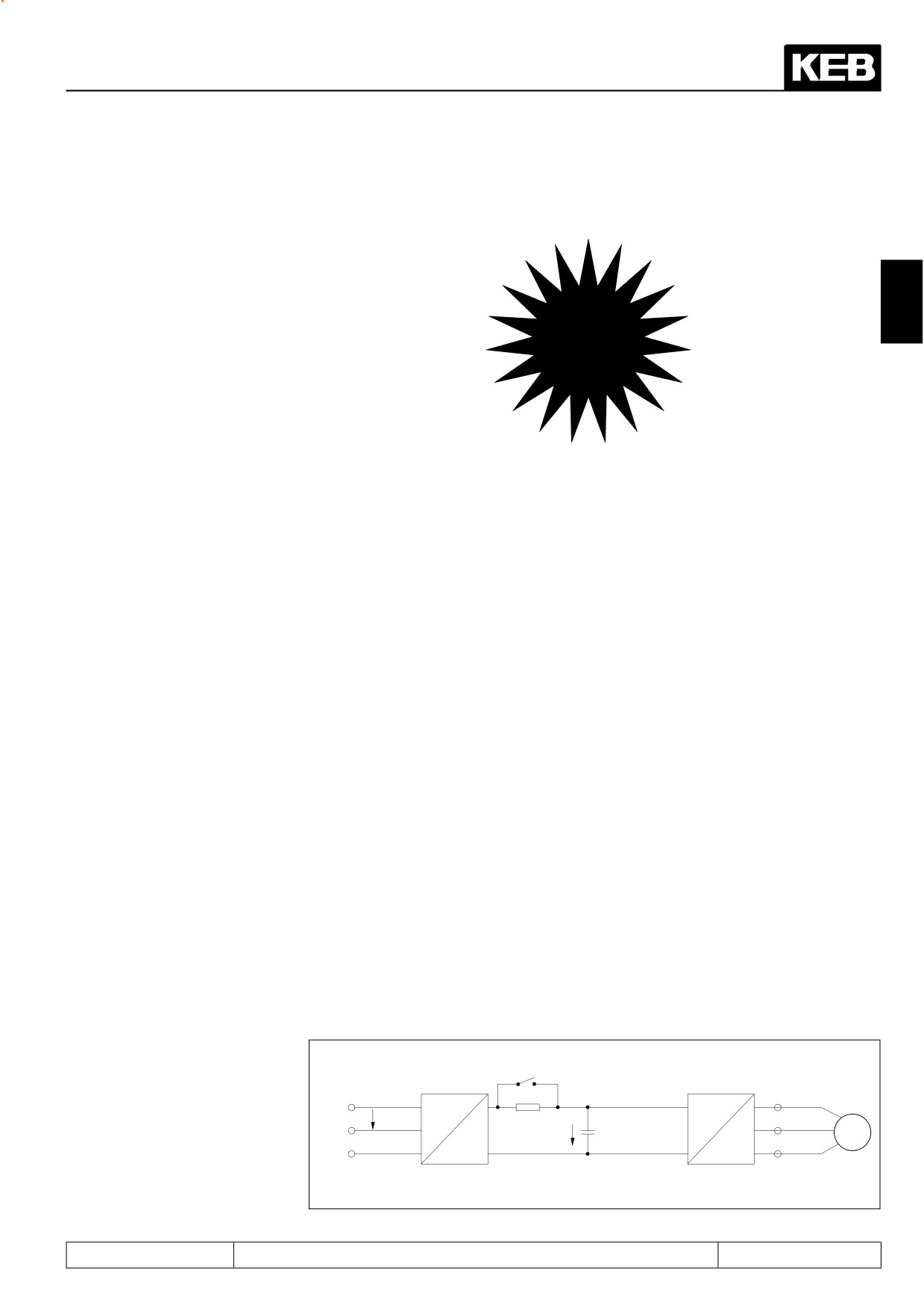
Function principle
The power circuit of a frequency inverter consists basically of a mains rectifier, the
DC-link and an inverter at the output. The mains rectifier consists of an uncontrolled
single or three-phase bridge connection, the single-phase design is restricted to small
powers. It converts the AC-voltage of the mains into a DC-voltage, which is smoothed
by the DC-link capacitor, thus in the ideal case (inverter unloaded) the DC-link is
charged with a voltage of UZK = √2
UN.
Since during the charging of the DC-link capacitor very high currents flow for a short
time which would lead to the tripping of the input fuses or even to the destruction of
the mains rectifier, the charging current must be limited to a permissible level. This is
achieved by using an inrush current limiting resistor in series to the capacitor. After
the charging of the capacitor is completed the limiting resistor is bridged, for example,
by a relay and is therefore only active at the switch-on of the inverter.
As the smoothing of the DC-link voltage requires a large capacity, the capacitor still has
a high voltage for some time after the disconnection of the inverter from the mains.
The actual task of the frequency inverter, to produce an output voltage variable in
frequency and amplitude for the control of the three-phase AC motor, is taken over
by the converter at the output. It makes available a 3-phase output voltage according
to the principle of the pulse-width modulation, which generates a sinusoidal current
at the three-phase asynchronous motor.
Fig. 2.1.2
Block diagram of an inverter power circuit
U
L1
UN
R
UZK
V
M
L2
C
3~
W
(L3)
Mains rectifier
DC-link
Converter
Motor
Page2.1 - 3
Product Overview
2.1.3
Application as directed
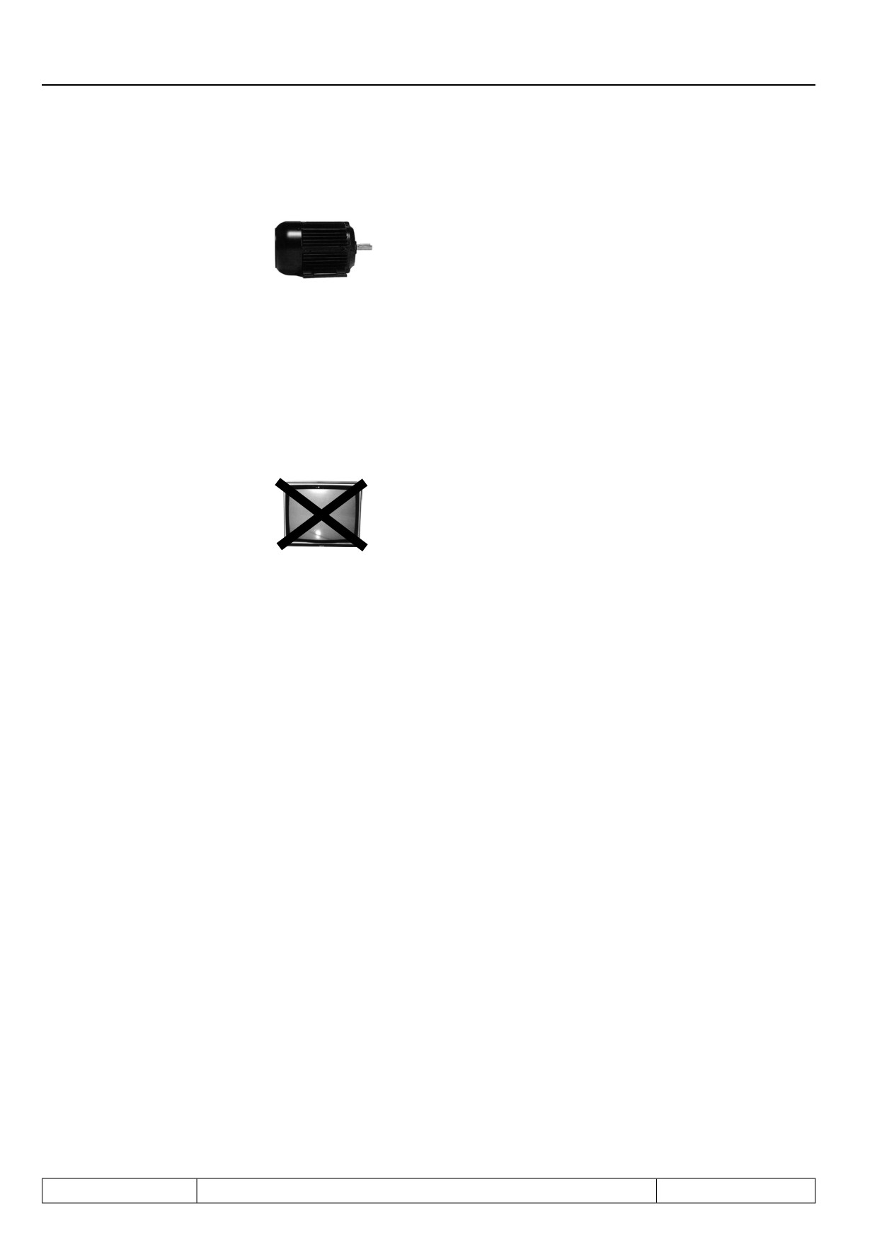
The KEB COMBIVERT is a frequency inverter with DC-voltage
link. It works according to the principle of the pulse-width mo-
dulation and serves exclusively for the stepless speed control
of three-phase AC motors.
The unit has been developed subject to the relevant safety
standards and is manufactured with the highest demands
on quality. Condition for an unobjectionable operation is the
function-conform configuring of the drive and correct transport
and storage as well as careful installation and connection.
The operation of other electric consumers is prohibited and can
lead to the destruction of the units as well as consequential
damages as a result from it.
Page2.1 - 4
Product Overview
2.1.4
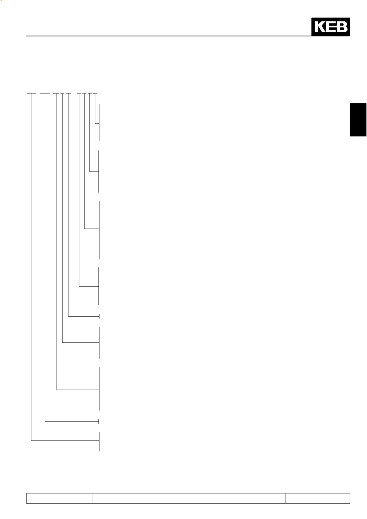
Type code
15.F5.A1E-35DA
At FI: Cooling
A-Z: As digits, varnished
At Servos: Motor cooling
0: Standard
A:
0 varnished (default)
0: Self-cooling
1: Flat rear
B:
1 varnished (flat rear)
1: External cooling
2
2: Water-cooled
C: 2 varnished (water cooling)
3: Convection
D: 3 varnished (convection)
4: Special fan
E:
4 varnished (special fan)
Encoder interface type see control part
0: no interface
5: resolver u. SSI
A: Inc. input a. Initiator F: Hiperface a. Inc. outp.
1: Inc. input a. Inc. I/O
6: Hiperface a. SSI
B: resolver u. Initiator
G: Inc. input a. Inc. input.
2: resolver u. Inc. I/O
7: Inc. input a. Tacho
C: Hiperface a. Initiator
H: resolver u. Inc. input.
3: Hiperface a. Inc. I/O
8: resolver u. Tacho
D: Inc. inp. a. Inc. outp.
I:
Hiperface a. Inc. inp.
4: Inc. input a. SSI
9: Hiperface a. Tacho
E: resolver u. Inc. output.
At FI: Switching frequency / max. short time current / OC-tripping current
0:
2 kHz/125%/150%
5:
4 kHz/150%/180% A:
8 kHz/180%/216% F:
16 kHz/200%/240%
1:
4 kHz/125%/150%
6:
8 kHz/150%/180% B: 16 kHz/180%/216% G:
2 kHz/400%/480%
2:
8 kHz/125%/150%
7: 16 kHz/150%/180% C:
2 kHz/200%/240% H:
4 kHz/400%/480%
3: 16 kHz/125%/150%
8:
2 kHz/180%/216% D:
4 kHz/200%/240% I:
8 kHz/400%/480%
4:
2 kHz/150%/180%
9:
4 kHz/180%/216% E:
8 kHz/200%/240% K: 16 kHz/400%/480%
At Servos: Motor speed
1: 1500 rpm
2: 2000 rpm
3: 3000 rpm
4: 4000 rpm
6: rpm
Input identification
0:
1ph 230V AC/DC
5:
400V DC A:
6ph 400V AC
1:
3ph 230V AC/DC
6:
1ph 230V AC z:
230V AC or AC/DC
2:
1/3ph 230V AC/DC
7:
3ph 230V AC Y:
400V AC or AC/DC
3:
3ph 400V AC/DC
8:
1/3ph 230V AC W:
230V DC
4:
230V DC
9:
3ph 400V AC V:
400V DC
Housing type
A, B, D, E, G, H, P, R, U, W
Accessory
0: without
4: PFC 2) integrated
5:
1: GTR 7 1)
GTR 7 1), PFC 2) integrated
2: integrated filter
6: integrated filter , integrated PFC 2)
3: GTR 7 1), integrated filter
7: GTR 7 1), integrated filter, integrated PFC 2)
Control type
B: BASIC (controlled frequency inverter with standard function)
C: COMPACT (controlled frequency inverter with enhanced function)
G: GENERAL (controlled frequency inverter with enhanced function)
M: MULTI (regulated, field-oriented frequency inverter for three-phase asynchronous motors)
S: SERVO (regulated frequency inverter for synchronous motors)
A: APPLIKATION (special software, e.g. S.C.L. for synchronous motors, controlled open loop)
Series F5
At FI in the 1. and 2. place Digit: Inverter size
At servos: Motor identification / motor dimension wide
1) GTR 7: Braking transistor
2) PFC:
Power factor control
Page2.1 - 5
Product Overview
Page2.1 - 6
Control Units
1.
Introduction
2.
Summary
3.
Hardware
3
4.
Operation
Selection of Operating
5.
Mode
6.
Initial Start-up
3.1
Control units
7.
Functions
8.
Error Assistance
9.
Project Design
10. Networks
11. Parameter Overview
12. Annex
Page3.1 - 1
Control Units
3.1.1
Terminal strip X2A
3.1 - 3
3.1.2
Connection of the control
3.1 - 4
3.1.3
Digital inputs
3.1 - 4
3.1.4
Analog inputs
3.1 - 5
3.1.5
Voltage input / external power supply
3.1 - 5
Page3.1 - 2
Control Units
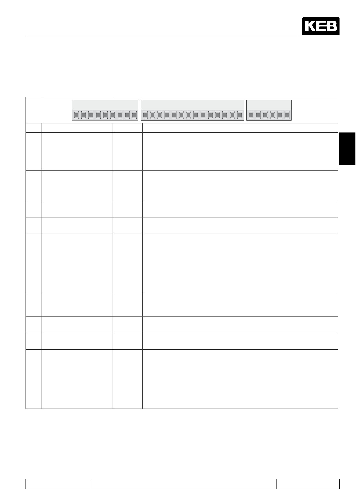
3.
Hardware
3.1
Control units
3.1.1
Terminal strip X2A
1
2
3
4
5
6
7
8
9
10 11 12 13 14 15 16 17 18 19 20 21 22 23
24 25 26 27 28 29
PIN
Function
Name
Description
1
+ Set value input 1
AN1+
The input signal 0...±10 V; 0...±20 mA a. 4...20 mA is defined with An.00/
2
- Set value input 1
AN1-
An.10. Specification and control see chap. 7.2.2.
3
3
+ Set value input 2
AN2+
Resolution: 12 Bit (11 Bit at F5 servo in the A-housing, Ri = 30 kΩ, scan
time: 1 ms / at fast setpoint setting: 250 µs
4
- Set value input 2
AN2-
(see. chapter 7.4.2)
5
Analog output 1
ANOUT1
The variable for outputting at analog output is determined with An.31 / 36.
Specification and control see chap.7.2.11
6
Analog output 2
ANOUT2
Voltage range:
0...±10V, Ri
=
100 Ω, resolution:
10 Bit,
PWM-Frequency: 3,4 kHz, filter response 1. order: 178 Hz
7
+10 V output
CRF
Reference voltage output +10 VDC +5% / max. 4 mA for set value poten-
tiometer
8
Analog mass
COM
Mass for analog in- and outputs
9
Analog mass
COM
Mass for analog in- and outputs
10
Progr. input 1
I1
Specifications, activation and programming of digital inputs see chapter
11
Progr. input 2
I2
7.3
12
Progr. input 3
I3
All digital inputs are free programmable. The control release
13
Progr. input 4
I4
is firmly linked with the input ST, but can be occupied with additional
14
Progr. input forward
F
other functions.
15
Progr. input reverse
R
Ri = 2,1 kΩ
16
Progr. input control rel.
ST
Scan time: 1 ms
17
Progr. input reset
RST
18
Transistor output 1
O1
Specifications, control and programming
19
Transistor output 2
O2
see chap. 7.3.12 ...7.3.22,
a total of max. 50 mADC for both outputs
20
+24 V output
Uout
approx. 24V DC output (max.100 mA)
21
20...30 V input
Uin
Voltage input for ext. supply, potential 0 V X2A.22/23
22
Digital mass
0 V
Potential for digital in-/outputs
23
Digital mass
0 V
Potential for digital in-/outputs
24
Relay 1 / NO contact
RLA
Programmable relay output 1 (terminal X2A.24...26);
25
Relay 1 / NC contact
RLB
Programmable relay output 2 (terminal X2A.27...29)
26
Relay 1 / switching
RLC
Specifications, control and programming of the relay outputs
27
contact
FLA
see chapter 7.3.12 ... 7.3.22
28
Relay 2 / NO contact
FLB
max. 30 V DC, 0,01...1 A
29
Relay 2 / NC contact
FLC
Relay 2 / switching
contact
Page3.1 - 3
//////////////////////////////////////////