KEB COMBIVERT F5-A,-E,-H 4.0. APPLICATION MANUAL (2008) - page 9
Motor Data and Controller Adjustments of the Asynchronous Motor
7.5.1
Open loop operation (V/F characteristic)
7.5 - 4
7.5.1.1
Rated frequency (uF.00), boost (uF.01) and delta boost (uF.04 / uF.05)
7.5 - 4
7.5.1.2
Maximum voltage mode (uF.10)
7.5 - 5
7.5.1.3
Additional rated point (uF.02/uF.03)
7.5 - 5
7.5.1.4
Voltage stabilization (uF.09)
7.5 - 6
7.5.1.5
Carrier frequency (uF.11)
7.5 - 7
7.5.1.6
Energy saving mode (uF.06...08)
7.5 - 7
7.5.1.7
SMM (sensorless motor management)
7.5 - 8
7.5.1.7.1
Motor name plate
7.5 - 8
7.5.1.7.2
Determination of the stator resistance (dr.06)
7.5 - 9
7.5.1.7.3
Load motor dependent para. (Fr.10), controller activation
7.5 - 9
7.5.1.7.4
Adjustment of the slip compensation (cS.00, cS.01, cS.04, cS.06, cS.09).
7.5 - 10
7.5.1.7.5
Improved slip compensation (cS.00 Bit 6 = 64, cS.03)
7.5 - 11
7.5.1.7.6
Adjustment of the torque compensation (uF.16, uF.17)
7.5 - 11
7.5.2
Vector controlled operation
7.5 - 12
7.5.2.1
Initial settings
7.5 - 12
7.5.2.1.1
Motor name plate data
7.5 - 12
7.5.2.1.2
Load motor dependent parameter
7.5 - 12
7.5.2.1.3
Speed feedback and motor rotation direction selection
7.5 - 14
7.5.2.2
Vector controlled operation without motor model
7.5 - 14
7.5.2.2.1
DASM rated speed
7.5 - 15
7.5.2.2.2
Flux reduction in the field weakening range
7.5 - 15
7.5.2.2.3
Magnetisation current adaption
7.5 - 15
7.5.2.3
Vector controlled operation with motor model (with encoder feedback)
7.5 - 16
7.5.2.3.1
Electrical parameters (equivalent circuit data) of the motor
7.5 - 16
7.5.2.3.2
Zusätzliche Abgleiche
7.5 - 20
7.5.2.3.3
Generally adjustments for operation with motor model
7.5 - 21
7.5.2.3.4
Magnetisation current adaption / with motor model
7.5 - 23
7.5.2.4
Vector control without speed feedback (ASCL)
7.5 - 23
7.5.2.4.1
ASCL / low speed operation
7.5 - 23
7.5.2.4.2
Switch to consecutive motor
7.5 - 26
7.5.2.4.3
Model adaption
7.5 - 26
7.5.2.4.4
Speed calc. ASCL (dS.14, 15) and
speed PT1-time ASCL (dS.17)
7.5 - 27
7.5.2.5
Special function: Rotor adaption
7.5 - 28
7.5.3
Block diagram
7.5 - 29
Page7.5 - 2
Motor Data and Controller Adjustments of the Asynchronous Motor
7.5
Motor data and controller adjustments of the asynchronous motor
The asynchronous motor has two principally different modes of operation:
- V/F characteristic operation
V/F characteristic operation, with SMM (Sensorless Motor Management) for speed stabilisation and miscella-
neous current limiting protective functions
- Vector controlled operation
During vector controlled operation, current and speed are checked by PI controllers.
The controlled operation can be carried out with or without motor model:
- Vector controlled operation without motor model
This mode of operation must be used if the electrical parameters (e.g., inductance) of a motor cannot be deter-
mined by automatic identification.
This operating mode always needs encoder feedback.
- Vector controlled operation with motor model
This operating mode can be used if the electrical parameters of the motor can be determined ("identified")
automatically.
The advantage of this operating mode is a higher torque accuracy compared to the operation without motor
model.
Particularly important for the motor model is the main inductance. This must be calibrated by a ramp-up of the
motor without load torque. For the other data (stator resistance, rotor resistance, leakage inductance), values
from a motor data sheet can be used alternatively.
7
- Vector controlled operation with motor model without encoder feedback (ASCL)
During vector controlled operation of an asynchronous motor without encoder feedback (Asynchronous Sen-
sorless Closed Loop => ASCL), the speed is estimated with a mathematical model of the asynchronous ma-
chine.
Standard version F5A does not contain operating mode ASCL. It needs the special software F5H.
Page7.5 - 3
Motor Data and Controller Adjustments of the Asynchronous Motor
7.5.1
Open loop operation (V/F characteristic)
7.5.1.1Rated frequency (uF.00), boost (uF.01) and delta boost (uF.04 / uF.05)
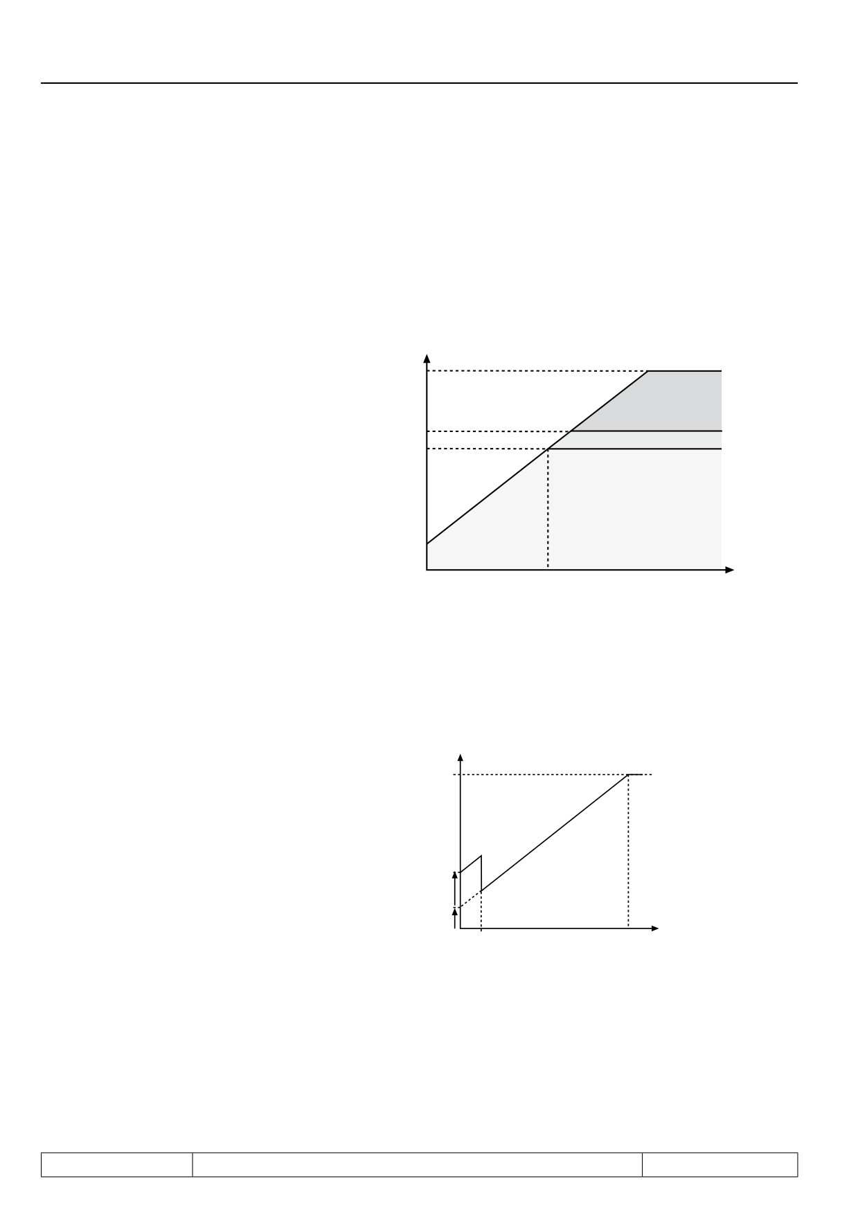
The voltage/frequency V/F characteristic is adjusted with the rated frequency (uF.00) and the Boost (uF.01).
The rated frequency adjusts the frequency at which 100 % modulation depth (~input voltage) are achieved. The
boost adjusts the output voltage to 0 Hz. Depending on uF.10 the modulation limit can be further increased in
this stage up to 200 % (see Fig.7.5.1.1).
UA
Figure
7.5.1.1a Rated frequency and
boost
U&
U&
uF.00 = 0,00...400 Hz; Default = 50 Hz
U&
uF.01 = 0,0...25,5 %; Default = LTK*
U&
U&
t
* LTK = power circuit-dependent
The Delta-Boost is a time-limited Boost used to overcome large breakaway torques. The Delta-Boost acts ad-
ding to the Boost; but the sum is limited to 25.5 %.
Figure 7.5.1.1b Delta boost
5!
uF.04 = 0,0...25,5 %; Default = 0 %
uF.05 = 0,00...10,00 s; Default = 0 s
U&
U&
T
U&
Page7.5 - 4
Motor Data and Controller Adjustments of the Asynchronous Motor
7.5.1.2Maximum voltage mode (uF.10)
By changing the maximal voltage mode more torque can be released free above the rated frequency through
overmodulation (110% voltage). Raising the U/f-characteristic has an influence at activated energy saving
function or at voltage stabilization.
uF.10 Maximum voltages mode
Value
Modulation
Description
100 % V/F / 100% vol-
without overmodulation; all limitations 100% of modulation factor
0
tage
110 % V/F
/
110% vol-
with overmodulation; all limitations 110% of modulation factor
1
tage
200 % V/F / 100% vol-
limitation of the voltage generating functions 200 %; limitation be-
2
tage
fore modulator 100% of modulation factor
200 % V/F
/
110% vol-
limitation of the voltage generating functions 200 %; 110 % output
3
tage
voltage
7.5.1.3Additional rated point (uF.02/uF.03)
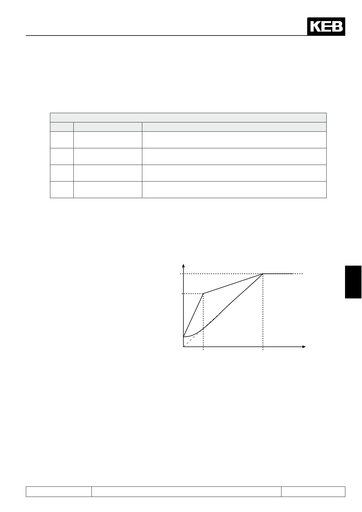
To adapt the V/F characteristic to special conditions an additional point of support can be specified with uF.02
and uF.03. uF.02 defines the frequency and uF.03 the voltage. At uF.02 = 0 Hz the adjustment is ignored.
Figure 7.5.1.3 Additional point of sup-
5!
port
7
U&
uF.02 = -1: Parabolic characteristic
0,0...400 Hz; Default = 0,0 Hz
uF.03 = 0,0...100,0 %; Default = 0,0 %
U&
FOUT
U&
U&
Page7.5 - 5
Motor Data and Controller Adjustments of the Asynchronous Motor
7.5.1.4Voltage stabilization (uF.09)
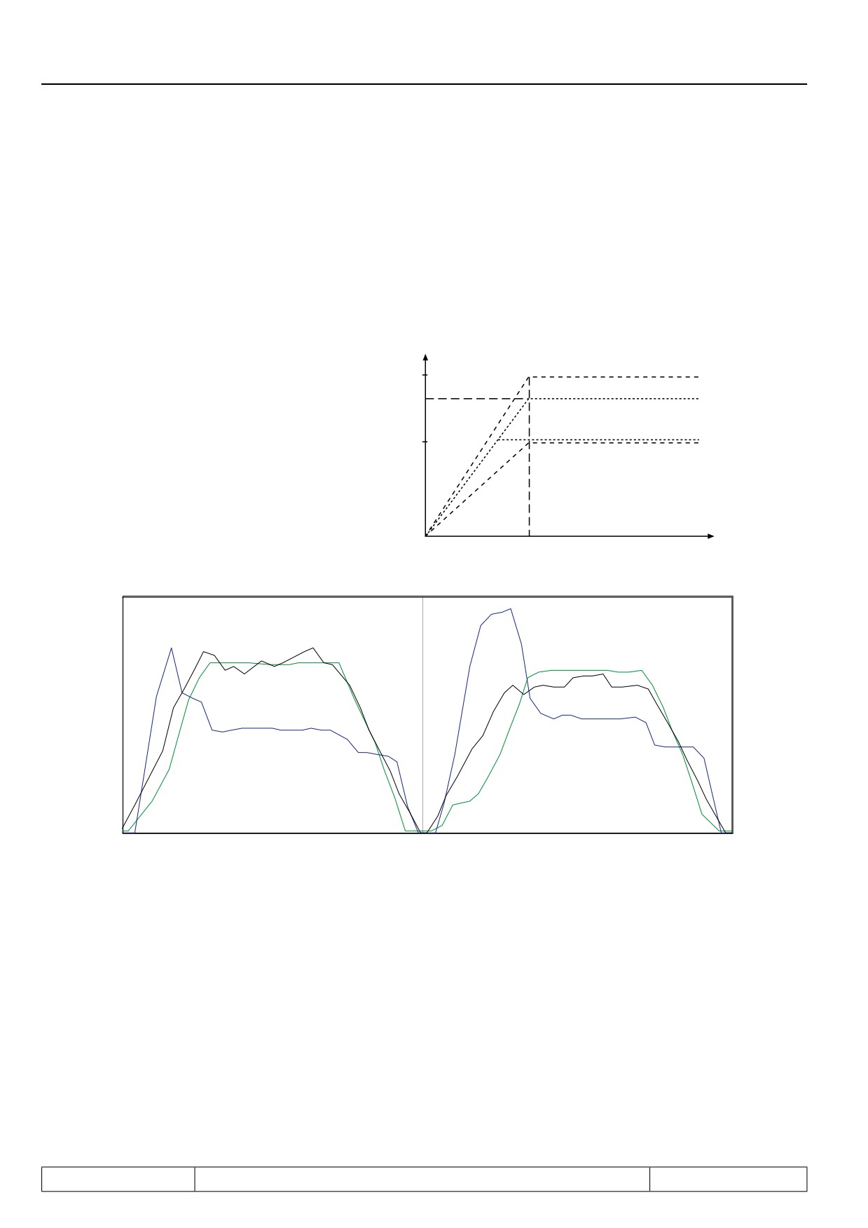
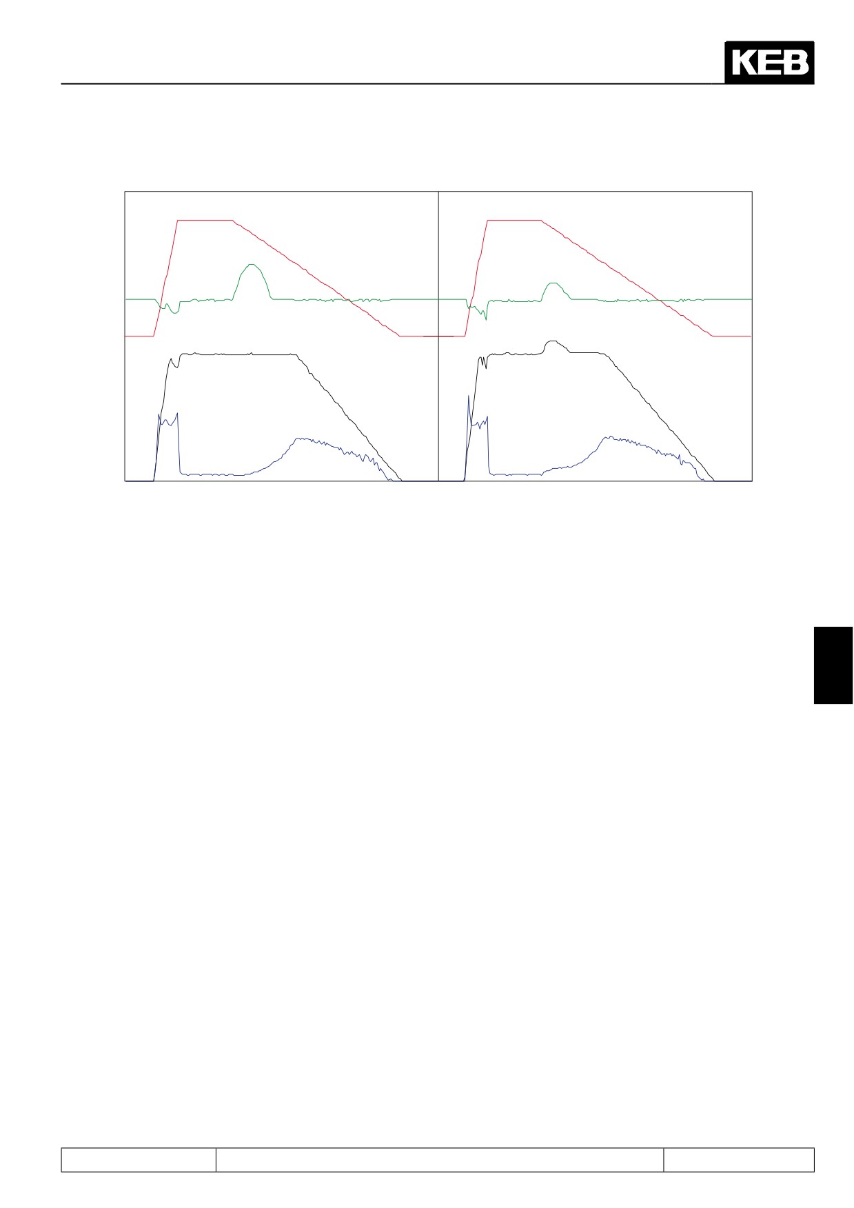
Due to fluctuations of the mains voltage or the load the DC-link voltage and with it the directly dependent out-
put voltage can change. In the case of enabled voltage stabilization the fluctuations of the output voltage are
compensated. I.e., 100% output voltage correspond to the value set in uF.09 , but maximally 110% · (UZK / √
2), depending on the setting of uf.10. This function further allows operation of motors with a low nominal voltage
at the inverter.
Figure 7.5.1.4a Voltage stabilization
5
UA at UN= 250V unstabilized
6
UA at UN= 250V stabilized
uF.09 = 230V
U
A at UN = 190V stabilised
Example:
uF.09 = 230V
6
UA at UN = 190V unstabilised
UN = Mains voltage
UA = Output voltage
F
uF.00 = 50 Hz
Figure 7.5.1.3b Example: Acceleration with load
with voltage stabilization
without voltage stabilization
Motor voltage
Motor speed
Motor voltage
Utilization
Utilization
Motor speed
Page7.5 - 6
Motor Data and Controller Adjustments of the Asynchronous Motor
Figure 7.5.1.3c Example: Deceleration of a high-inertia drive from 80Hz
With stabilization
Without stabilization
Actual frequency
Actual frequency
DC link voltage
DC link voltage
Motor voltage
Motor voltage
Utilization
Utilization
7.5.1.5Carrier frequency (uF.11)
Information on the carrier frequencies can be found in chapter 7.10.3 "Carrier frequencies and Derating".
7.5.1.6Energy saving mode (uF.06...08)
The energy saving mode allows the lowering or raising of the current output voltage. Corresponding to the ac-
7
tivation conditions defined in uF.06, the voltage corresponding to the V/f characteristic is scaled by the energy
saving factor (uF.07).
If torque compensation is active (s. chapter 7.5.1.7), the energy saving function is used for control optimization.
The V/f characteristic will then not be affected.
The maximum output voltage cannot be higher than the input voltage, even for a factor > 100 %.
The function is used for example in cyclic executed load/no-load applications. During the no-load phase the
speed is maintained, but energy is saved as a result of the voltage reduction.
uF.07 Energy saving factor
0,0…130,0 % (default 70 %)
uF.08 Energy saving input selection
0...4095 (Default 0)
For the assignment of the inputs to the parameter values, refer to chapter 7.3.1 "digital inputs".
Page7.5 - 7
Motor Data and Controller Adjustments of the Asynchronous Motor
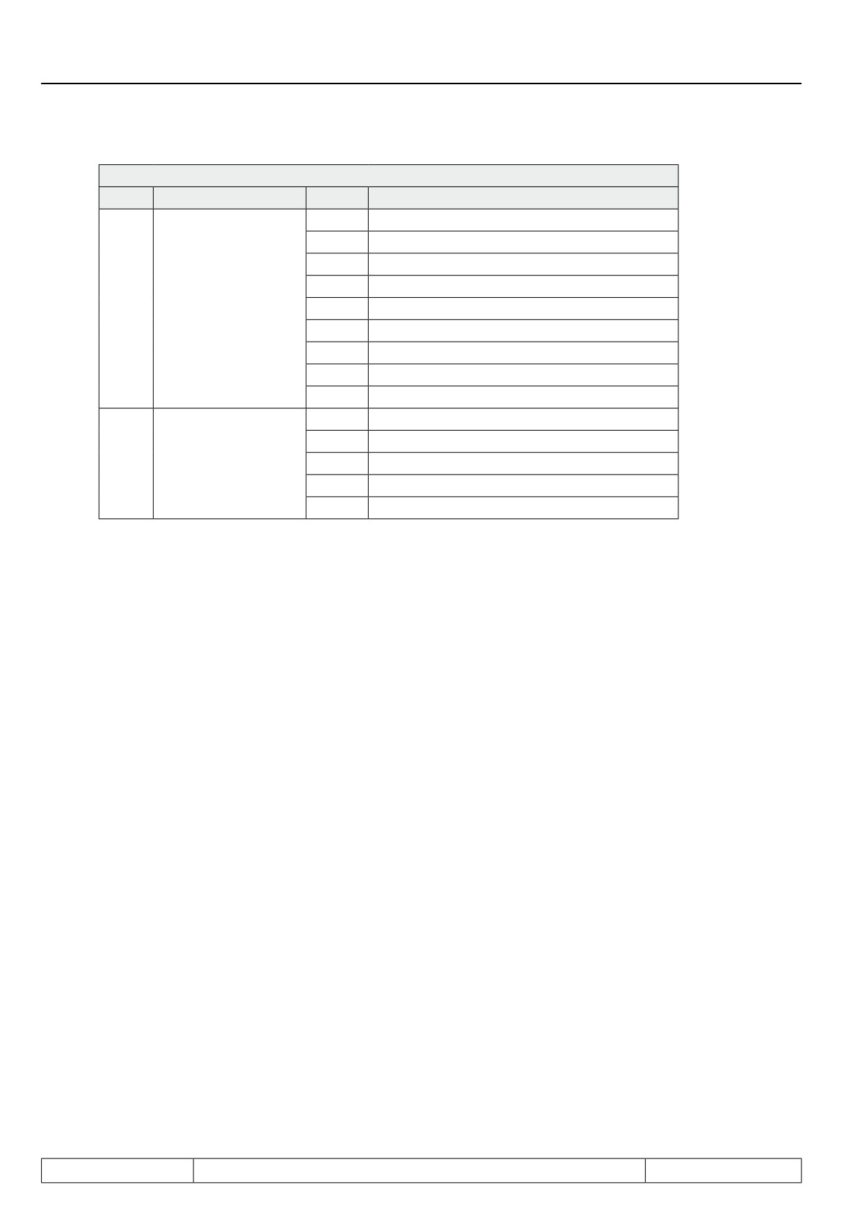
uF.06 Energy saving mode
Bit
Description
Value
Function
0
generally off
1
generally active
2
at actual value = setpoint
3
via digital input
0...3
Activation
4
at clockwise rotation
5
at counter clockwise rotation
6
at constant run clockwise
7
at constant run counter-clockwise
8...15
generally off
0
Standard time *
16
time / 2
4...7
Voltage ramp
32
time / 4
48
time / 8
64
time / 16
* default setting 1,6s
7.5.1.7SMM (sensorless motor management)
The SMM-function (sensorless motor management) includes the torque and slip compensation. These two
functions can be activated separately. For an optimal control characteristic, the combination of both functions
is required.
Setting the correct motor data is required, since they are used in calculations needed by the inverter to achieve
the best possible results in the control of boost and slip.
Torque compensation
Torque compensation adapts the voltage at variable load torques in such a way that the magnetizing current is
kept constant. With it a higher maximum torque is achieved at small output frequencies compared to uncom-
pensated operation. (block diagram see chapter 7.5.3.)
7.5.1.7.1
Motor name plate
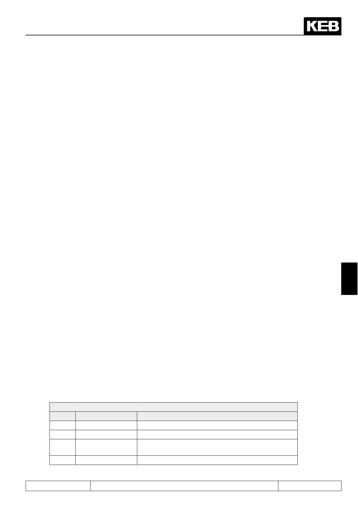
Following parameters can be taken directly from the name plate and entered:
-
dr.00 DASM rated current
-
dr.01 DASM rated speed
-
dr.02 DASM rated voltage
-
dr.03 DASM rated power
-
dr.04 DASM cos (phi)
-
dr.05 DASM rated frequency
Page7.5 - 8
Motor Data and Controller Adjustments of the Asynchronous Motor
!! Parameter dr.00 and dr.02 are always to be adjusted according to the used wiring (star/delta).
The following parameters can be taken from the corresponding data sheet or can be determined from mea-
surements:
-
dr.06 DASM stator resistance
-
dr.09 breakdown factor
7.5.1.7.2
Determination of the stator resistance (dr.06)
The stator resistance can either be measured with an ohmmeter or determined automatically.
In this way the ohmic line resistance is registered simultaneously (important in the case of long incoming
lines).
For the measurement with an ohmmeter, the connection between motor and inverter has to be broken. The
measurement is carried out on a warm motor, between 2 phases of the motor feed cable, independent of the
motor wiring (Δ / Y). For a more accurate result, all 3 values (U/V, U/W and V/W) should be measured and the
values then be averaged.
The automatic determination can be carried out for each parameter set separately. Thus a parameter set can
be programmed for example as "Warm-up set" for particularly critical applications.
Adhere to the following procedure:
-
Input motor data of the identification plate into the parameter set which is to program.
-
possibly call and activate parameter set
-
Execute the measurement dependent on the operational case in cold status respectively let the motor
warm up to operating temperature.
-
Preset no direction of rotation (inverter must be in status "LS")
7
-
Activate control release
-
maximum value "250000" of parameter dr.06 starts the resistance measurement
During the determination the status display (ru.00) indicates "Cdd". Upon successful determination the motor
stator resistance is entered in dr.06. If an error occurs during the determination then the error signal "E.Cdd"
is output.
7.5.1.7.3
Load motor dependent para. (Fr.10), controller activation
After input of the rating plate data of a new motor or after the automatic measurement of the stator resistance,
an automatic optimisation of the torque and slip compensation can be carried out with Fr.10 (s. chap. 7.5.1.7).
The optimization is started by writing value "3" on Fr.10. At that the inverter must be in the status "noP" (no
control release). Provided that only one motor is used, the measurement can occur with direct set programming
for all parameters at once.
Fr.10 load motor dependent parameter
Value
Function
Description
0
finished
loading completed
1
uF.09
only for closed loop operation
Actual DC link vol-
only for closed loop operation
2
tage
3
SMM
Adjustment for torque and slip compensation
Page7.5 - 9
Motor Data and Controller Adjustments of the Asynchronous Motor
Following parameters are changed by the activation of Fr.10:
-
uF.00 rated frequency = Motor rated frequency (dr.05)
-
uF.01 boost = calculated value
-
uF.02 additional frequency = -0,0125 Hz (parabolic characteristic)
-
uF.02 additional voltages = 0,0%
-
uF.09 voltage stabilization = rated motor voltage (dr.02)
-
uF.16 autoboost configuration = 1 (sign-sensitive)
-
uF.17 Autoboost gain = 1,2 (Default value)
-
cS.00 Speed control configuration = 34 (speed control SMM + breakdown slip limit (dr.09))
-
cS.01 actual source = 2 (calculated)
-
cS.04 speed control limit (vvc) = 4 • nominal slip of the motor
-
cS.06 KP speed = 50
-
cS.09 KI speed = 500
The adaption should cover approx. 90 % of the applications. For an application-specific adjustment a manual
fine adjustment can now still be carried out for an individual case.
7.5.1.7.4
Adjustment of the slip compensation (cS.00, cS.01, cS.04, cS.06, cS.09)
The integrated speed controller is used at cS.00 = "2" for the slip compensation.The rotor speed calculated
from the motor model is selected as the actual controller value by cS.01 = 2.
With bits 3-6 in cS.00, the slip compensation can be configured.
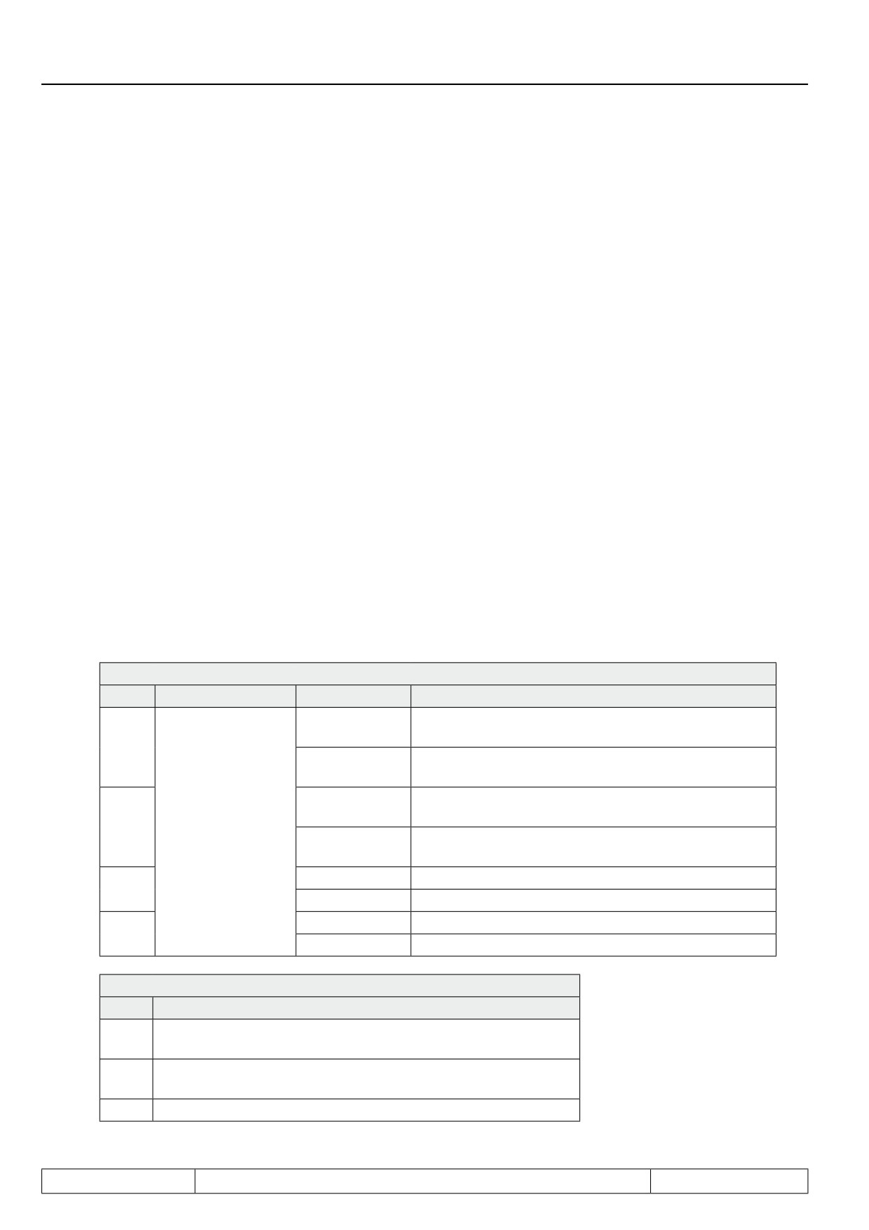
cS.00: Speed control configuration
Bit
Meaning
Value
Explanation
Change of direction of rotation via the controller not
0
possible
3
Change of direction of rotation via the controller pos-
8
sible
no controller intervention for controller setpoint
= 0
0
min-1
4
Control mode
controller intervention even for controller setpoint = 0
16
min-1
0
no breakdown slip limit
5
32
breakdown slip limit (Nennschlupf x dr.09)
0
Default slip compensation
6
64
Improved slip compensation (cS.03)
cs.01: Actual source
Value
Explanation
0
Encoder interface channel 1, only reasonable for closed-loop
operation
1
Encoder interface channel 2, only reasonable for closed-loop
operation
2
calculated rotor speed
Page7.5 - 10
Motor Data and Controller Adjustments of the Asynchronous Motor
cS.04 Speed control limit (vvc)
0…4000 1/min x resolution factor (dependent on ud.02)
Default: 750 1/min x resolution factor
The speed limit determines the maximum controller intervention.
cS.06 KP speed, cs.09 KI speed
0…32767, default 300(KP), 100(KI)
Proportionality and integration factor, respectively, of the speed controller.
ATTENTION! These parameters must be adjusted before activation of the slip compensation. The default va-
lues are optimised for closed-loop operation.
This adaption is carried out with the motor adaption (see chapter 7.5.1.7.3), and only a fine adjustment is ne-
cessary.
7.5.1.7.5
Improved slip compensation (cS.00 Bit 6 = 64, cS.03)
During the standard slip compensation, the slip is calculated proportionately from the effective current. This
calculation becomes imprecise above the nominal setpoint and in generatoric operation.
For the improved slip compensation, the slip calculation during motor operation above the nominal setpoint is
approximated to the real M/n-characteristic with a parabolic function. Greater inaccuracies will then occur only
above twice the rated torque.
During generatoric operation, the linear dependency is preserved. The steepness of the characteristic can be
adjusted with cS.03.
7.5.1.7.6
Adjustment of the torque compensation (uF.16, uF.17)
7
With uF.16 and uF.17 the torque compensation is activated and configured.
Magnetising current setpoint and actual value are calculated in the motor model.
ATTENTION! Through overcompensation increased motor currents can occur particularly with small frequen-
cies.
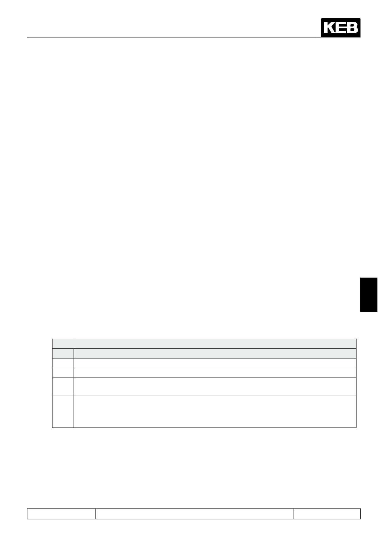
uF.16: Autoboost configuration
Value
Meaning
0
Torque compensation off
1
Torque compensation acts motoric and generatoric
Torque compensation works only in the motoric operation; resulting in a smoother run in the gene-
2
ratoric operation.
Torque compensation in motoric operation; overcompensation in the generatoric operation; resulting
in a higher maximum torque and increased current in the generatoric operation compared to 1 and
3
2; because of the higher motor-own losses a braking resistor is only necessary at higher energy
recovery compared to 0, 1 and 2.
uF.17 Autoboost gain
0,00…2,50 (default 1,20)
With the energy saving function (uF.06...uF.08, s. chapter 7.5.1.7.5), the magnetizing current setpoint can be
adjusted to the application. If a drive operates in the partial load range for a long period, decreasing the energy
saving factor can reduce motor warming and energy consumption.
Page7.5 - 11
Motor Data and Controller Adjustments of the Asynchronous Motor
7.5.2
Vector controlled operation
7.5.2.1Initial settings
Vector controlled operation is activated by inputting the values 4, 5 or 6 into the category "control mode" of the
parameter "speed control configuration" (cS.00).
cS.00: Speed control configuration
Bit
Meaning
Value
Explanation
0: off
1..3
reserved for V/F open loop operation
speed- and current-controlled operation
4: Speed control
0..2
Control mode
with or without speed feedback
5: Torque control
torque-controlled operation / see chapter
7.9
6: torque value (F5M/S)
7: off
Torque-controlled operation (cS.00 = 5 or 6) is a special form described in chapter 7.9.
The following adjustments are required in speed-controlled operation for all modes (with / without encoder and
with / without motor model, respectively):
7.5.2.1.1
Motor name plate data
Input of the motor rating plate data is at the beginning of each start-up:
- dr.00 DASM rated current
- dr.01 DASM rated speed
- dr.02 DASM rated voltage
- dr.03 DASM rated power
- dr.04 DASM cos(phi)
- dr.05 DASM rated frequency
7.5.2.1.2
Load motor dependent parameter
after inputting this data, the operator must switch to closed-loop operation (cS.00 = 4) and input Fr.10 = 1 or 2
(explanation see below) once.
Fr.10 Load mot. dependent parameter
Value
Function
1:uF.09 (F5-M/ S)
precharging dependent on the voltage class of the inverter, and the value
of uf.09, respectively
2: act. DC link voltage (F5-M/ S)
precharging dependent on the current DC link voltage of the inverter
3: Start motor adaption (F5-G)
only for open loop V/F characteristic operation
The inverter must have status "noP", i.e., the input "control release" (ST) may not be set.
Thus the following parameter are pre-charged dependent on the motor and inverter data:
Page7.5 - 12
Motor Data and Controller Adjustments of the Asynchronous Motor
Definition of the limiting characteristic:
-
dr.16 DASM max. torque corner speed
-
dr.17 DASM speed for max. torque
-
dr.18 DASM field weakening speed
Definition of magnetisation:
-
dr.19 Flux adaption factor
-
dr.20 Field weakening curve
Current controller
-
dS.00 KP current
-
dS.01 KI current
Torque limits:
-
cS.19 Abs. torque ref
-
cS.20...cS.23 Torque limit (clockwise rotation motor operation, counter clockwise rotation motor operati-
on, clockwise rotation generator operation, counter clockwise rotation generator operation)
-
Pn.61 Quick stop torque limit
Flux controller:
-
dS.11 KP flux
-
dS.12 KI flux
-
dS.13 Magnetising current limit
7
Inertia:
-
cS.25 Inertia (kg x cm^2)
speed controller (preloaded only if automatic speed controller setting is activated by cS.26 ≠ 0):
-
cS.06 KP speed
-
cS.09 KI speed
only for ASCL (F5-H):
-
dS.14 KP speed calculation ASCL
-
dS.15 KI speed calculation ASCL
-
dS.19 Limit uf-control dec ASCL
Some of these parameters (e.g., the limiting characteristic) depend upon the available voltage.
During vector controlled operation, the voltage stabilization generally should be "off". The software-integrated
current controllers control the voltages and a simultaneous intervention of the voltage stabilization increases
the system´s vibrational tendencies.
uF.09 Voltage stabilization
Value
Function
1120
off
Page7.5 - 13
Motor Data and Controller Adjustments of the Asynchronous Motor
With Fr.10 = 1, precharging occurs dependent on the voltage class of the inverter (400V or 230V)
The current DC link voltage of the frequency inverter, which is proportional to the supply input voltage, is con-
sidered for the calculations at Fr.10 = 2.
If the parameter "voltage stabilization" (uF.09) is not set to the default value "1120: off", then the value set in in
uF.09 is taken as the reference voltage for the calculations for settings Fr.10 = 1 or 2.
If the drive is to be operated at a different voltage then during initial start-up, proceed as follows:
In parameter uF.09, enter the nominal voltage to be used later, activate Fr.10 = 1 and reset parameter uF.09 to
"off".
Attention:
After completion of a possible "fine tuning", i.e., the manual adjustment of controller parameters, torque limits,
etc., parameter Fr.10 may not be activated anymore. Otherwise, the manually adjusted parameters will be
overwritten by the calculated values!
7.5.2.1.3
Speed feedback and motor rotation direction selection
The actual value source for the speed must be selected in parameter cS.01.
Possible values for drives with tachometer generator are 0 (speed measurement via encoder interface channel
1) or 1 (speed measurement via encoder interface channel 2).
Description of the correct parameter setting of the encoder interfaces is made in chapter 7.11 "speed measure-
ment".
If operation without tachometer generator is desired, cS.01 = 2 (calculated actual value) must be selected.
This setting is possible only for open loop V/F characteristic operation (for software type F5-A) or for control via
motor model (for software type F5-H and F5-E, respectively).
cS.01 Actual source
Bit
Description
Value
Function
0: Channel 1
Control to measured speed (via encoder interface 1)
1: Channel 2
Control to measured speed (via encoder interface 2)
0...1
Actual value source
2: Calculated actual va-
Control to calculated speed (from motor model)
lue
0: off
2
System inversion
Activates the system inversion
4: an
With activation of the system inversion it is reached that the motor with selected rotation direction "clockwise"
(e.g. by setpoint- or rotation setting) has the physically direction "counter clockwise" respectively at setting
"counter clockwise" the physical rotation "clockwise". Precondition is a correct wiring of motor and speed feed-
back (if available).
One possible application of this function is, e.g., the deployment of 2 drive units, where facing motors drive the
same shaft. If system inversion is activated for a drive, the same setpoint can be set for both via a control, even
if one motor rotates clockwise and the other counter clockwise.
For applications with encoder feedback, the same function can be activated by switching on system inversion
in parameter Ec.06 (see chapter 7.11).
7.5.2.2Vector controlled operation without motor model
For motors that don´t allow identification of the motor data (e.g., no-load operation of the motor not realisable),
vector controlled operation without motor model must be selected.
In vector controlled operation without motor model, the parameters dr.06...dr.10 have no function. If the drive is
to be operated with motor model, chapter 7.5.2.2 can be skipped.
Page7.5 - 14
Motor Data and Controller Adjustments of the Asynchronous Motor
7.5.2.2.1
DASM rated speed
In vector controlled operation without motor model, the slip is affected significantly by the rated speed. If the
drive requires too much current for a certain load, or if is can be seen that the output voltage at high load gets
too small, an incorrect (too low) rated speed may be the cause.
In this case, the rated speed must be adjusted in small increments until the optimum is found.
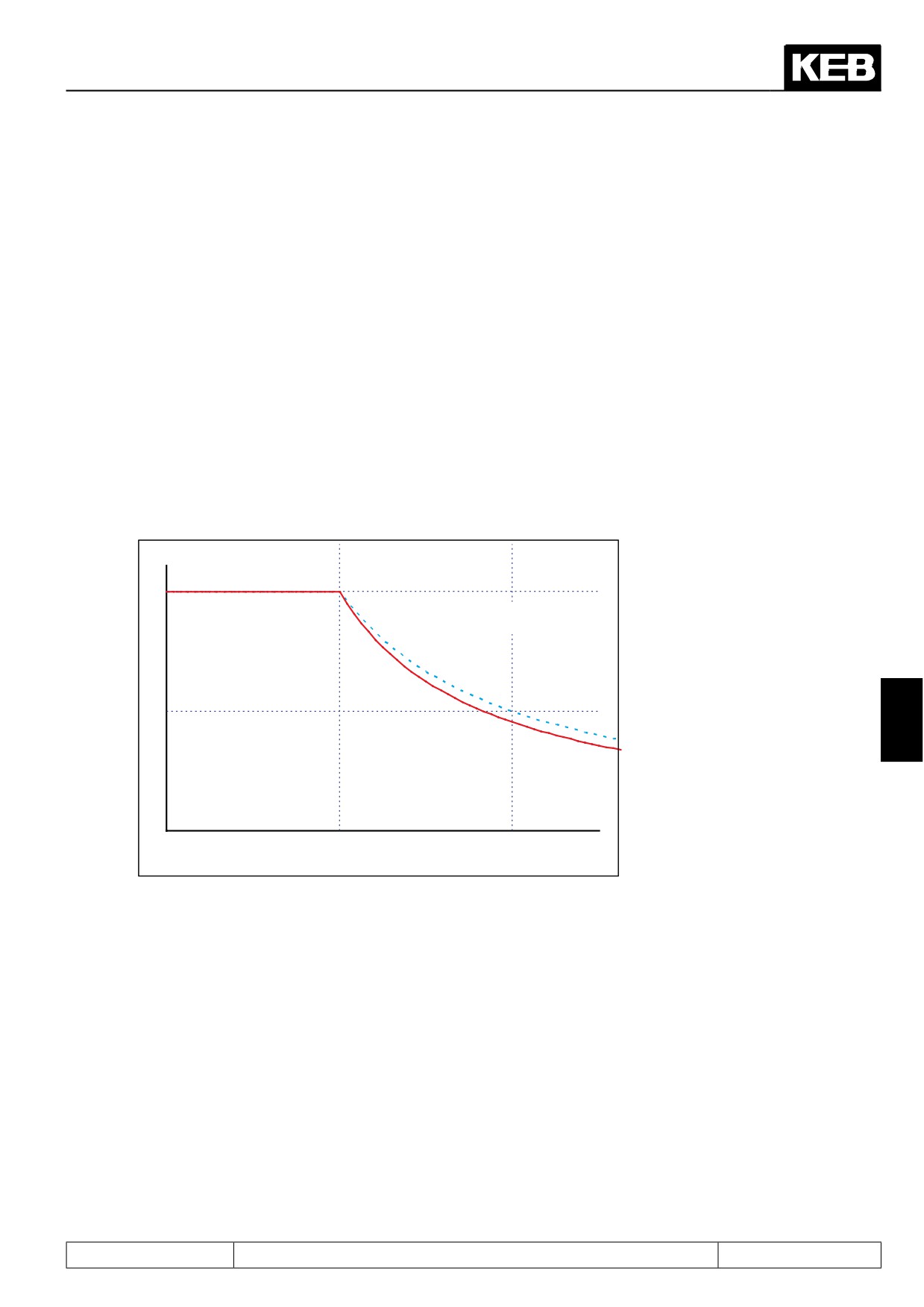
7.5.2.2.2
Flux reduction in the field weakening range
Since the motor voltage is proportional to frequency * flux, the flux must be lowered according to a 1/x function
above the rated point (maximum voltages reached) to keep the voltage constant.
In the base speed range of the motor, the maximum torque is limited by the current the inverter is able to sup-
ply. In the field weakening range, the achievable torque is additionally limited by the voltage.
Since the motor parameters, like main inductance, change in the field weakening range, the flux does not fol-
low the desired 1/x-characteristic during control without motor model in the field weakening range.
This change in the main inductance can partially be compensated for with the default setting of the amplifica-
tion factor field weakening (dr.20) of 1.2 instead of 1.
Motor flux
1
Field weakening curve (dr.20) = 1
=> 1 / x flux reduction
0,5
7
Field weakening = 1,2
dr.18
2 * dr.18
Actual frequency [rpm]
For an optimum motor adaption, this factor may have to be modified .
The flux reduction is well parametrised, if for every operating point a voltage reserve of approx. 3...10% is
available. I.e., the modulation factor (ru.42) should be (dr.18) ca. 90...97% under nominal load at the field
weakening speed.
7.5.2.2.3
Magnetisation current adaption
For large motors, the automatic calculation of the magnetising current occasionally returns values that are too
large. This value can be reduced by adjusting the parameter "flux adaption factor" (dr.19).
Whether the automatically calculated magnetising current is too large, can be tested by accelerating the drive
to the field weakening speed (dr.18) in vector controlled operation with no load. At this speed, the average va-
lue of the modulation factor should not exceed 90%. If this value is exceeded, the factor "flux adaption factor"
(dr.19) should be reduced.
Page7.5 - 15
Motor Data and Controller Adjustments of the Asynchronous Motor
7.5.2.3
Vector controlled operation with motor model (with encoder feedback)
The vector controlled operation with motor model is possible only if the electrical characteristic data of a motor
are known. For this operating mode, the motor model calculation must be activated in parameter dS.04.
dS.04 Flux / rotor adaption mode
Bit
Meaning
Value
Explanation
0: off
0
Motor model (ASM)
Activation of the motor model calculation
1: on
7.5.2.3.1
Electrical parameters (equivalent circuit data) of the motor
For the vector controlled operation with motor model, the electrical characteristic data of the motor must be
known.
The parameters TPIM stator resistance (dr.06), TPIM leakage inductance (dr.07) and TPIM rotor resistance
(dr.08) can be taken from a motor data sheet or can be automatically determined by the KEB COMBIVERT
using the motor identification. For motors with high power, the resistances are very small (a few mΩ). This can
lead to error in the automatically identification. For these motor, it may be sensible to use the value from the
motor data sheet for dr.08.
Due to saturation, the parameter dr.10 "TPIM main inductivity" depends on the chosen magnetising current.
This is defined by the rated motor current (dr.00), cos(phi) (dr.04) and factor flux adaption (dr.19). Since the va-
lue of the main inductance given in the motor data sheet possibly applies for a different current, this parameter
(dr.10) must always be identified, to ascertain the correct value of the current magnetising current.
7.5.2.3.1.1
Identification / general
The required equivalent circuit data for the motor model can be determined by the KEB COMBIVERT itself.
First the motor data must be entered and the motor adaption must be executed according to chapters 7.6.1.
There are two possibilities to start the identification:
-
Writing of parameter dr.48 in inverter state "stop (mod. off)", measurement is starting
automatically.
-
Writing of parameter dr.48 in inverter state "nop" with subsequent control release.
Parameter dr.48 cannot be written in other operating conditions.
The measured values can be invalid in case of strong overdimensioning of the inverter. The rated current of the
motor should be at least 1/3 of the maximum short time current limit. The short time current limit is determined
by the overload characteristics and can be taken from the power circuit manual or parameter In.18 (hardware
current).
The direction of rotation during identification of the main inductance is always "clockwise rotation"!
During the calibration, the value of "82: calculated drive data / Cdd" is displayed in the inverter status ru.00.
After successful completion of the calibration, the display is ru.00 = "127: final calculated drive data / Cddr".
If the measurement is interrupted with an error, ru.00 = 60ERROR! drive data/ E.Cdd" is displayed.
No correct operation can be ensured in case of an abort.
The current state of the identification is displayed in parameter dr.62 "state motor ident." The control release
must be switched off in order to leave the identification mode.
Parameter dr.48 must be written again in order to start a new measurement.
Page7.5 - 16
Motor Data and Controller Adjustments of the Asynchronous Motor
If the internal brake handling is used in the application, then it must be deactivated for the identification. For
safety reasons the output signal "brake release" is not set during measurement, since the motor cannot gene-
rate a defined torque in this time. Stator resistance, rotor resistance and leakage inductance can be measured
also at engaged brake.
For the identification of the main inductance, the drive must be decoupled from the load, and the output switch
condition associated with the break control must be set to the value "1" (= always active), setting the brake
permanently open.
7.5.2.3.1.2
Automatic mode
For the identification of the parameters, automatic mode should generally be used.
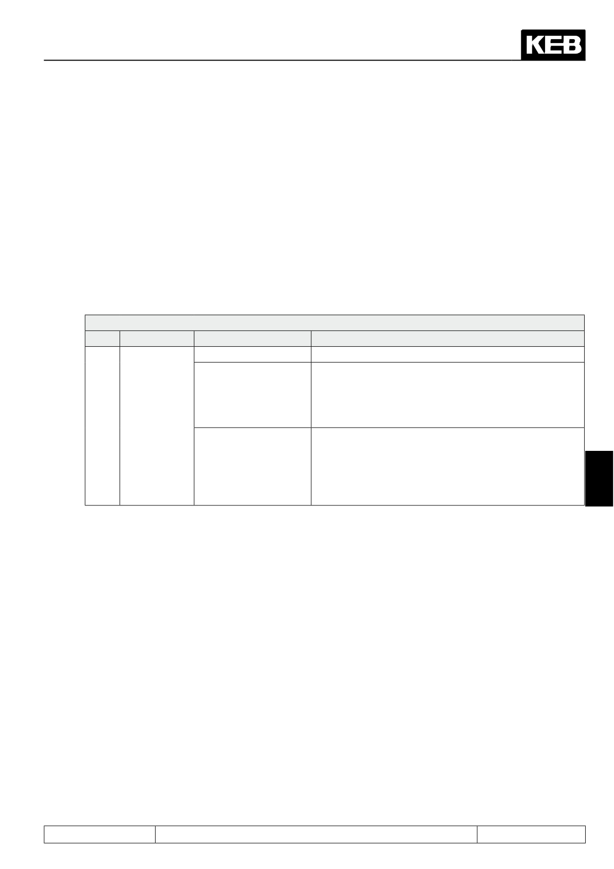
Automatic mode is the simplest method of parameter identification.
Measurement of the dead time compensation characteristics, as well as the stator- and rotor resistance and the
leakage inductance is done in standstill. A small rotation of the motor caused by the test signals is possible.
dr.48 Motor identification
Bit
Description
Value
Function
0: off
7: Auto ident. without
automatic measurement of the dead time characteristic
main inductance (ASM)
and of all equivalent circuit data - with the exception of the
/ EMK (SM) !without ro-
main inductance. This measurement is carried out with the
tation!
motor stopped, but a rotation of the motor due to the test
signals is possible.
0...4
Measurement
!Attention: requires motor revolution in no-load ope-
ration!
8: complete Auto Identi-
automatic measurement of the dead time characteristic
fication !with rotation!
and of all equivalent circuit data - including main induc-
7
tance.
The motor accelerates to "speed for max. torque" (dr.17)
It is necessary for the identification of the main inductance, that the motor accelerates to the speed for maxi-
mum torque (dr.17) and then it operates in no-load operation.
There is a special ramp "Lh. ident. acc/dec time" (dr.49) for identification.
This ramp applies during calibration of the main inductance for the acceleration to dr.17 and the deceleration
at the end of the identification.
The speed controller must be sensibly parametrised (choose small Ki), the drive may not vibrate during the
identification.
The following chapter, "single identification", contains more detailed information with respect to the separate
steps of the identification and can be skipped if automatic mode is chosen. In the chapter after the next, "ad-
ditional trimmings", two further identifications are described which are not part of the automatic mode and that
are unnecessary in many cases.
The explanations of the parameters required to be set continues in chapter 7.5.2.3.3 "generally required set-
tings for operation with motor model".
Page7.5 - 17
Motor Data and Controller Adjustments of the Asynchronous Motor
7.5.2.3.1.3
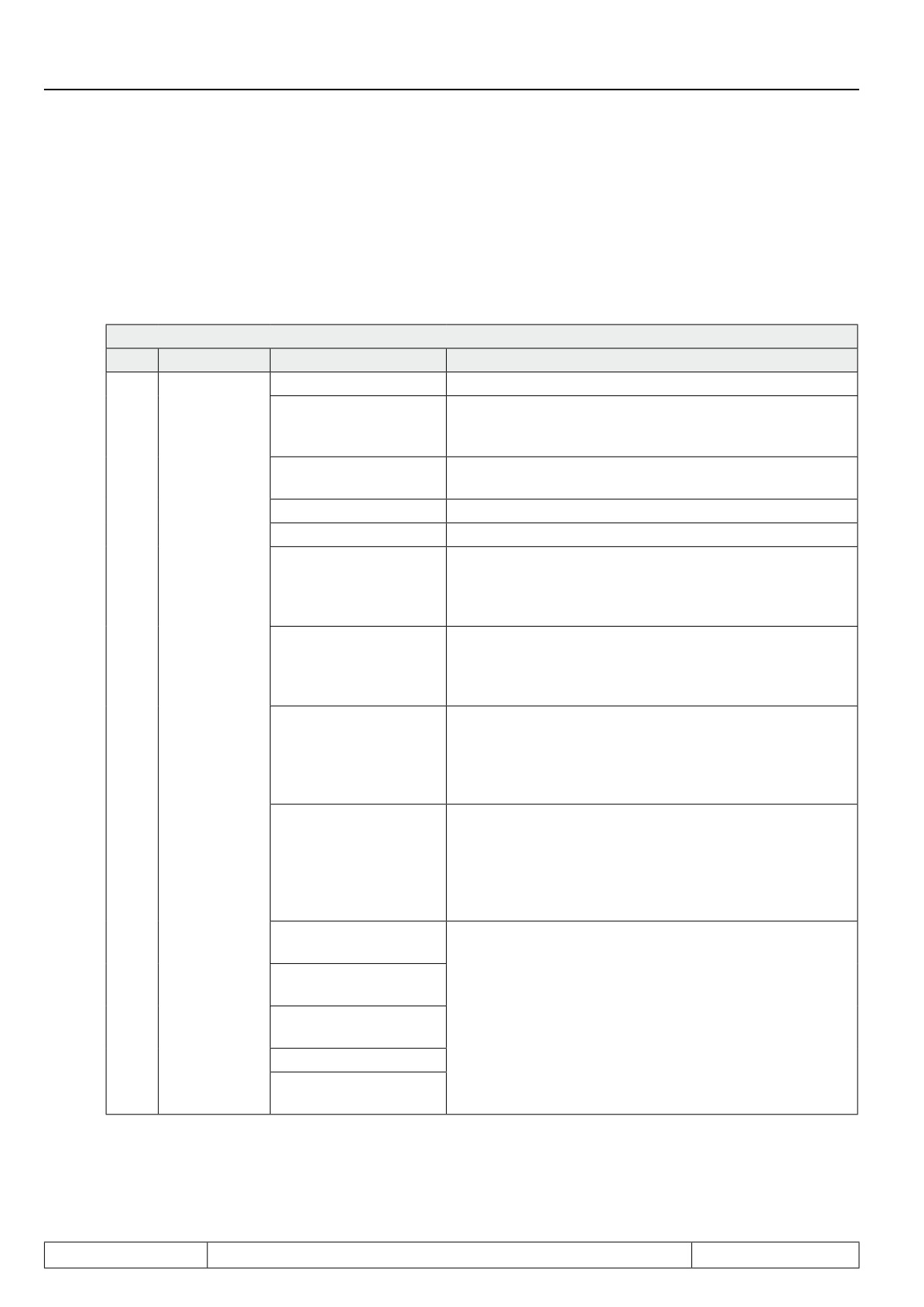
Single identification
Single identifications should not be used for the first measurement of the motor parameters, since invalid mea-
suring results can occur in case of a wrong identification sequence or omitting of individual points.
Single identification can always be used if a complete automatic measurement was executed and only indivi-
dual parameters shall be identified. For example this can be a resistance measurement in warm condition or a
new measurement of main inductance after changing parameter dr.19 "flux adaption factor".
dr.48 Motor identification
Bit
Description
Value
Function
0: off
1: Calculation of the
Precharging of the current controller parameters and main
main inductance (ASM)/
inductance from rating plate data
EMK (SM)*
2: Leakage (ASM)/ win-
Measurement of the leakage inductance
ding inductance (SM)*
3: Stator resistance Rs*
Measurement of the stator resistance
4: Rotor resistance Rr *
Measurement of the rotor resistance
Based on the equivalent circuit data, the model parame-
5: Model-/controller pa-
ters and the setting of the controller are determined in the
rameterization *
dS-parameters (current-, flux-, and speed calculation con-
troller)
6: Main inductance
!Attention: requires motor revolution in no-load ope-
(ASM)/ EMK (SM) !with
ration!
rotation! *
Measurement of the main inductance at "speed for max.
torque" (dr.17)
7: Auto ident. without
automatic measurement of the dead time characteristic
main inductance (ASM)
and of all equivalent circuit data - with the exception of the
0...4
Measurement
/ EMK (SM) !without ro-
main inductance. This measurement is carried out with the
tation!
motor stopped, but a rotation of the motor due to the test
signals is possible.
!Attention: Requires motor revolution in no-load ope-
8: Complete Auto Iden-
ration!
tification !with rotation!
automatic measurement of the dead time characteristic
and of all equivalent circuit data - including main induc-
tance.
The motor accelerates to "speed for max. torque" (dr.17)
9: Dead time detection
2 kHz *
10: Dead time detection
4kHz *
Measurement of dead time compensation characteristics
11: Dead time detection
for different switching frequencies
8kHz *
12: reserved
13: Dead time detection
16 kHz *
Page7.5 - 18
Motor Data and Controller Adjustments of the Asynchronous Motor
0: 1000Hz
32: 500Hz
64: 250Hz
The measuring frequency is changed independently duri-
Output
fre-
96: 125Hz
ng measurement.
5...7
quency
128: 62,5Hz
Therefore, leave the value at 0: 1000Hz!
Only changeable for test and diagnostics purposes.
160: 32,25Hz
192: 15,625Hz
224: 7,8125Hz
* at dr.48 = 8 auto-identification
Pre-adjustment of the main inductance (dr.48 = 1)
With dr.48 = 1 (calculation of the main inductance (ASM) / EMC(SM)), a starting value for the main inductance
is calculated from the motor label data.
Leakage inductance measurement (dr.48 = 2)
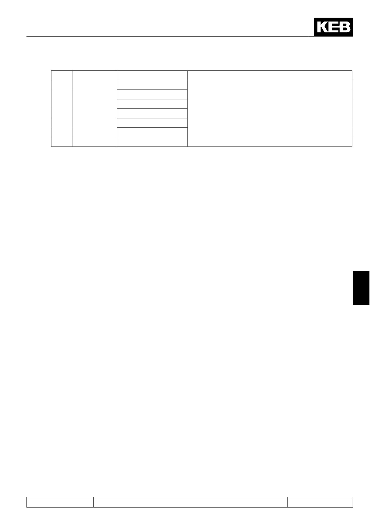
Measurement of the leakage inductance (dr.07) occurs at standstill with a test signal. The frequency of the
measurement signal is adjustable via bits 5... 7 in parameter dr.48.
Since the inverter determines automatically the ideal measuring frequency, value 0 should be always selected
for bits 5... 7.
Stator resistance measurement (dr.48 = 3)
7
Measurement of the stator resistance is done with DC current.
Rotor resistance measurement (dr.48 = 4)
Measurement of the rotor resistance (dr.08) occurs at standstill with a test signal. The frequency of the mea-
surement signal is adjustable via bits 5... 7 in parameter dr.48.
Since the inverter determines automatically the ideal measuring frequency, value 0 should be always selected
for bits 5... 7.
Since the measurement frequency occasionally has to be reduced to 7.8125 Hz for better measurement accu-
racy, the motor may rotate.
Model / controller parameterization (dr.48 = 5)
With dr.48 = 5, the internal model parameters as well as current-, flux- and speed calculation controller parame-
ters are calculated from the equivalent circuit data. If a mode other than automatic is used for the identification,
this action should be taken after the measurement of the leakage inductance, rotor and stator resistance, but
before the identification of the main inductance, so that the controllers for the speed ramp-up are parametrised
correctly.
Page7.5 - 19
Motor Data and Controller Adjustments of the Asynchronous Motor
Main inductance (ASM) / EMK (SM) with rotation (dr.48 = 6)
It is necessary for the identification of the main inductance that the motor accelerates to the speed for maximum
torque (dr.17). The speed controller must be sensibly parametrised (choose small Ki), the drive may not vibrate
during the identification.
The motor must be able to rotate in no-load operation. After the main inductance has been identified, the drive
stops automatically.
There is a special ramp "Lh. ident. acc/dec time" (dr.49) for identification. This ramp applies for acceleration at
the beginning and deceleration at the end of the identification.
Dead time detection (dr.48 = 9...13)
The dead time detection only works as single identification if the stator resistance is correct preset.
The measured dead time values can be read out via In.39 and In.40.
The dead time compensation characteristic is not contained in the data protection by reading of a complete list,
because it is specific for the respective inverter.
The calibrated dead time compensation characteristics are in force if uF.18 = 3 is set.
7.5.2.3.2
Zusätzliche Abgleiche
dr.48 Motor identification
Bit
Description
Value
Function
0: off
14: Torque detection 2
kHz
15: Torque detection 4
Detection of the no-load torque at different switching fre-
kHz
quencies. During operation this torque is subtracted from
16: Torque detection 8
torque display ru.12.
0...4
Measurement
kHz
17: reserved
18: Torque detection 16
kHz
19: Current offset de-
Detection of the current offset in phase U and V
tection
20: Voltage pulse
Only for synchronous motor
7.5.2.3.2.1
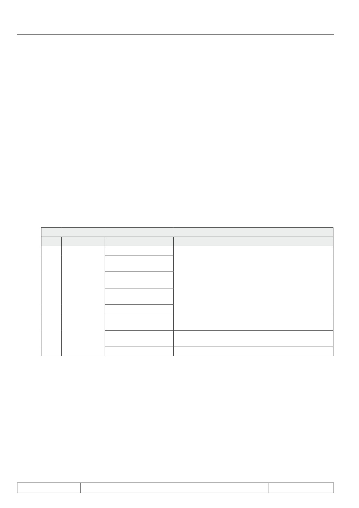
Torque detection (dr.48 = 14...18) / only for F5H-M
In applications with particularly high demands on accuracy of the torque display, this can be calibrated.
As a standard, the torque display does not show a value of 0 in encoderless operation during no-load opera-
tion. The reason for this is switching frequency-dependent losses in the inverter and friction losses due to the
application.
If the torque display has to be corrected for this offset, the torque offset of the whole drive can be calibrated with
dr.48 = 14...18 for the various switching frequencies.
Thereby the drive accelerates in stepwise with the adjusted ramp in dr.49 to maximum 1,3-fold synchronous
speed. The speed limits set in the oP-parameters remain operative during this phase.
Page7.5 - 20
Motor Data and Controller Adjustments of the Asynchronous Motor
The calibrated no-load torque is stored as correction characteristic. During operation, the display of the actual
torque in ru.12 is corrected using this characteristic.
The torque offset-characteristic can be read with parameter dr.58/ dr.59.
The characteristic is not part of the data backup created by read out of a complete list.
This should be executed only if the application really requires increased torque accuracy. Since the trimming
values are not contained in the complete list, porting the data to a different inverter is labour-intensive.
7.5.2.3.2.2
Current offset detection (dr.48 = 19)
As a standard, the current offset from the inverter is permanently ascertained and balanced, as long as the
modulation is switched off. Therefore, the current offset-detection via dr.48 is usually not required.
In some cases, one achieves more accurate current offset values if one carries out the trimming with current
in the motor.
If dr.48 = 19 is selected, the inverter provides a test signal to the motor and so carries out the trimming once.
A disadvantage of this current offset detection is that it is carried out only once and therefore temperature and
ageing effects are not taken into account.
To preserve the identified offset, automatic measurement is deactivated with dr.48 = 19.
ATTENTION! Since the automatic measurement can only be reactivated by the KEB service personnel, the
current offset detection should preferably be carried out only in consultation with KEB.
7.5.2.3.3
Generally adjustments for operation with motor model
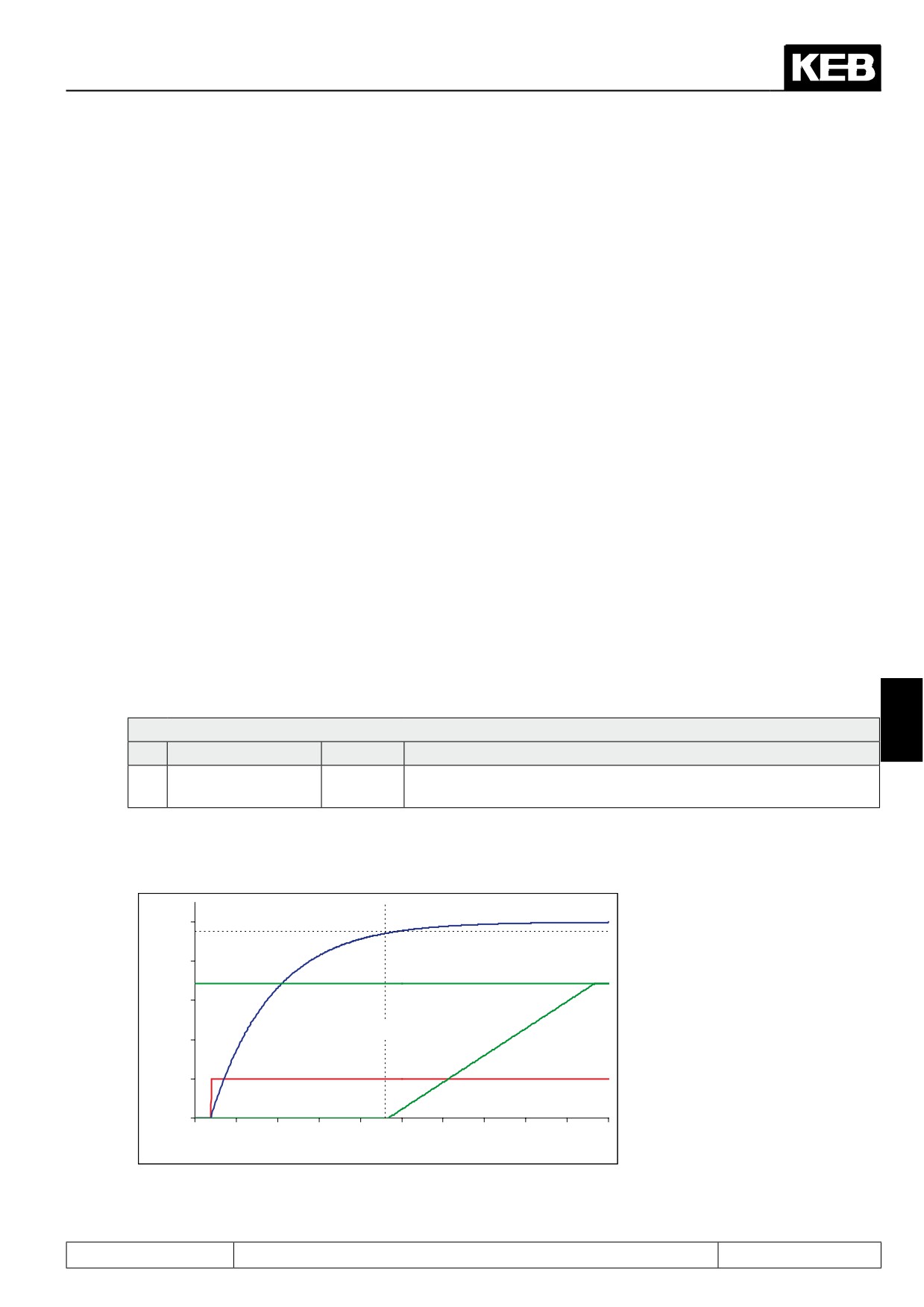
The drive is only ready for operation after switching the modulation if the flux is build up. If one starts earlier,
the drive can display undefined behaviours (erroneous torque display, too high currents, poorer controller be-
haviour).
7
dS.04 : Flux / rotor adaption mode
Bit
Meaning
Value
Explanation
Wait for magnetisati-
0: off
the speed setpoint (ru.01) is applied only after the flux reduction, i.e.,
7
on (ASM)
128: on
only then will ramps and speed controller become active
Bit 7 in dS.04 ("Wait for magnetisation (ASM)") must therefore always be set (value 128). Thus the setpoint
setting is only released if the flux is build up to 95%.
100%
Flux / rated flux
80%
Set value display (ru.01)
60%
Ramp output display (ru.02)
40%
Control release (ST)
20%
0%
0
0,1
0,2
0,3
0,4
0,5
0,6
0,7
0,8
0,9
1
Time [s]
The flux controller must be activated for the operation with motor model.
Page7.5 - 21