KEB COMBIVERT F5-A,-E,-H 4.0. APPLICATION MANUAL (2008) - page 12
Speed Control
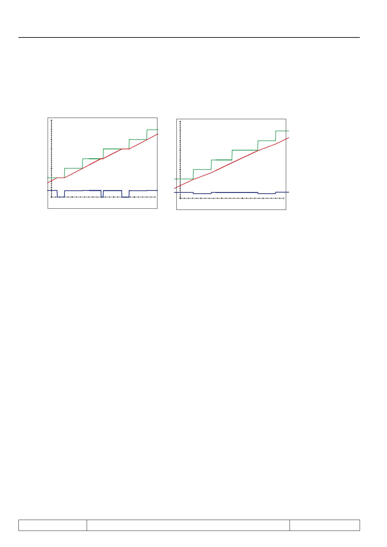
with reference splitting and variable clock time of the external control
The longest clock time (in ms) must be entered in parameter oP.74 "reference splitting"
for optimal pre-control with non-constant clock time of the external control.
This causes a short delay of the reference value, but also a smoother precontrol va-
lue.
op.74 = Time for shortest
op.74 = Time for the longest
setpoint setting cycle
setpoint setting cycle
Setpoint setting of
Setpoint setting of
external control
external control
Setpoint speed
before ramp (ru.01)
Setpoint speed
before ramp (ru.01)
Pre-control value for the
Pre-control value for the
acceleration torque
acceleration torque
Time [ms]
Time [ms]
Page7.7 - 8
Torque Display and -Limiting
7.1
Operating and appliance data
1.
Introduction
7.2
Analog in- and outputs I
2.
Summary
7.3
Digital in- and outputs
3.
Hardware
7.4
Setpoint-, rotation- and ramp adjustment
Motor data and controller adjustments of the asynchronous
7.5
4.
Operation
motor
Motor data and controller adjustments of the synchronous
7.6
motor
Selection of Operating
5.
Mode
7.7
Speed control
6.
Initial Start-up
7.8
Torque display and -limiting
7.9
Torque control
7.
Functions
7
7.10
Current control, -limiting and switching frequencies
8.
Error Assistance
7.11
Speed measurement
9.
Project Design
7.12
Positioning and synchronous control
7.13
Protective functions
10. Networks
7.14
Parameter sets
11. Parameter Overview
7.15
Special functions
12. Annex
7.16
CP-Parameter definition
Page7.8 - 1
Torque Display and -Limiting
7.8.1
Maximum voltage controller, voltage limit
7.8 - 3
7.8.2
Physical torque limits ASM
7.8 - 4
7.8.2.1
Torque limits in the base speed range
7.8 - 4
7.8.2.2
Torque limits in the field weakening range
7.8 - 4
7.8.3
Physical torque limits DSM
7.8 - 6
7.8.3.1
Torque limits in the base speed range (dr.27, dr.15)
7.8 - 6
7.8.3.2
Torque limits in the field weakening range
7.8 - 6
7.8.3.2.1
Determination of the magnetising current limit (dS.13)
7.8 - 7
7.8.3.2.2
Definition of the limiting characteristic
7.8 - 8
7.8.3.2.3
Shifting of the limiting characteristic
7.8 - 10
7.8.3.2.4
Effect of the current limit
7.8 - 12
7.8.4
Setting of the application-dependent torque limits
7.8 - 13
7.8.5
Display of the actual torque values and limits
7.8 - 14
7.8.6
Display of the torque-related motor workload (ru.90)
7.8 - 14
7.8.6.1
Mode 1: "Reference torque" Le 27 = 0
7.8 - 14
7.8.6.2
Mode 2: "Reference torque" Le 27 unequal 0
7.8 - 15
Page7.8 - 2
Torque Display and -Limiting
7.8
Torque display and -limiting
Several factors limit the maximally available torque of a drive: in the base speed range, the current available
from the inverter, and in the field weakening range, additionally, the voltage that limits the breakdown torque of
the motor. Furthermore, some applications also demand a limiting of the torque, e.g., to protect the mechanical
parts.
7.8.1
Maximum voltage controller, voltage limit
To settle the current, the inverter always needs a voltage control reserve. If the output voltage gets too high
(greater than dS.10 "Umax modulation reference"), the maximum voltage controller intervenes and counter-
acts the excessive voltage. By entering the values 8 or 24 in the item "maximum voltage controller" of the
parameter dS.04 "flux/ rotor adaption mode", the maximum voltage controller is activated.
For value 0 or 16, the controller is switched off.
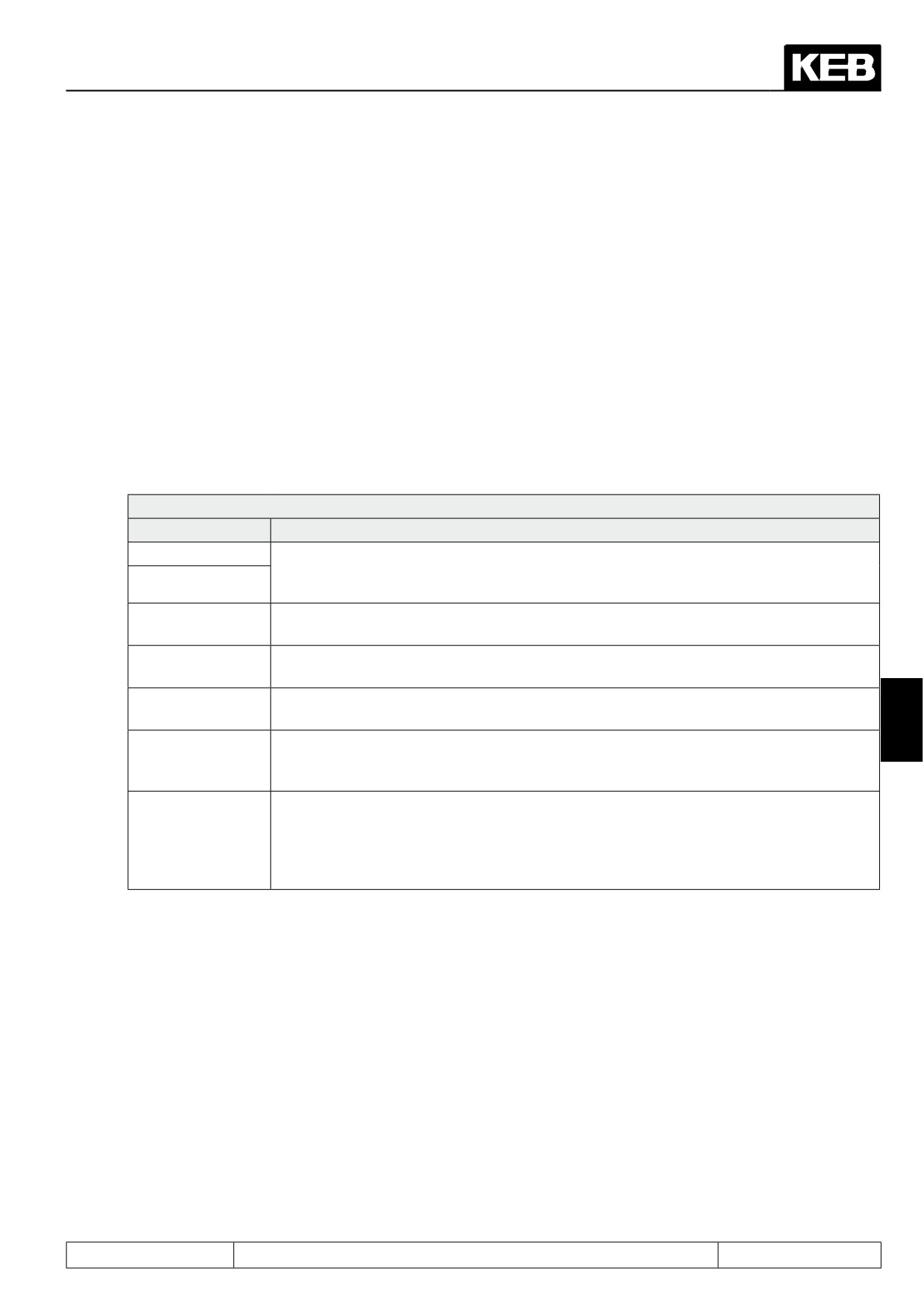
dS.04: Flux / rotor adaption mode
Bit
Meaning
Value
Explanation
0: off, max. 110%
controller off, max. modulation factor =110%
controller on,
Maximum voltage control-
8: on, max. 110%
3, 4
max. modulation factor = ds.10 + 2%
ler
16: off, max. 100%
controller off, max. modulation factor =100%
24: on, max. 100%
controller on, max. modulation factor =100%
The voltage range for which a modulation factor > 100% is needed is designated as overmodulation range.
The voltages in this range are no longer sinusoidal, which leads to distortions in the phase currents, noisy
speed estimation during encoderless operation, and inferior moment accuracy.
These disadvantages are offset by a higher output voltage.
7
With the selection of "max. 100%" (value 16 and 24), overmodulation is not permitted. This setting should only
be selected if the drive is operated in a mode with motor model (with or without speed feedback).
For the selection "max. 110%" (value 0 or 8), the available voltage increases due to exploitation of the non-
sinusoidal overmodulation range.
The value 0 should not be used since the negative effects are very serious.
At value 8, the negative effects are minimised by limiting the overmodulation range to "Umax modulation
reference" dS.10 + 2% . I.e., if dS.10 = 103% is selected, the maximum modulation factor is 105%. This limit
applies only to the overmodulation range.
The values 0 and 8 should only be used after careful testing.
The controller is adjusted via parameters dS.08 "KP Umax", dS.09 "KI Umax", dS.10 "Umax modulation refe-
rence".
dS.08 has only a small effect and can be left at the value 0.
dS.09 determines the dynamic of the controller. If this parameter is set too small, the drive can reach the vol-
tage limit. If this parameter is set too high, the drive begins to vibrate. If the modulation factor becomes much
noisier due to an increase of dS.09, it indicates that the controller setting is too high.
Temporarily reaching the voltage limit normally poses no problems.
Parameter dS.10 determines which modulation factor has control. The closer this is to 100%, the better the
inverter voltage is utilised, but also the lower are the control reserves useable for the dynamic.
The default value of 97% is usually a good compromise.
For the asynchronous machine, the voltage limitation occurs by flux reduction.
The motor flux can be reduced by the controller to ¼ of the value it would have according to the magnetising
characteristic.
For the synchronous machine, the voltage limitation is done by setting a negative magnetising current. The
maximum value of this current is set with the parameter dS.13 "magnetising current limit". (Regarding effect
and setting of dS.13 see chapter 7.8.3 physical torque limits of the synchronous motor).
Page7.8 - 3
Torque Display and -Limiting
7.8.2
Physical torque limits ASM
7.8.2.1Torque limits in the base speed range
In parameter dr.14, the rated torque (calculated from rated power and rated speed) of the motor is displayed.
In dr.15, the maximum torque (limited by the maximum current of the inverter) is displayed.
If hardware current limiting is activated (uF.15 = 1 or 2), the maximum current is equal to the hardware current
level (In.18) minus a safety reserve of 5% of the inverter rated current.
If hardware current limiting is deactivated (uF.15 = 0), the maximum current is equal to the overcurrent error
limit minus a safety reserve of 10%.
Additionally, the motor current can be limited through software with the parameter dr.37 "maximum current"
(see chapter 7.10.2). This limitation also affects the maximum achievable torque, but is not shown in dr.15.
Through the torque limitation, the active current is limited simultaneously in the base speed range . Due to the
additional magnetising current, the current limit of the inverter can still be exceeded. Therefore, the current
limiting through software should additionally be activated.
7.8.2.2Torque limits in the field weakening range
When the motor overloads, i.e., when a torque upwards of its torque limit is demanded from it, the maximum
voltage controller reduces the flux too much and thereby also reduces the maximum achievable torque.
Therefore, the maximum permissible torque must be reduced in the field weakening range.
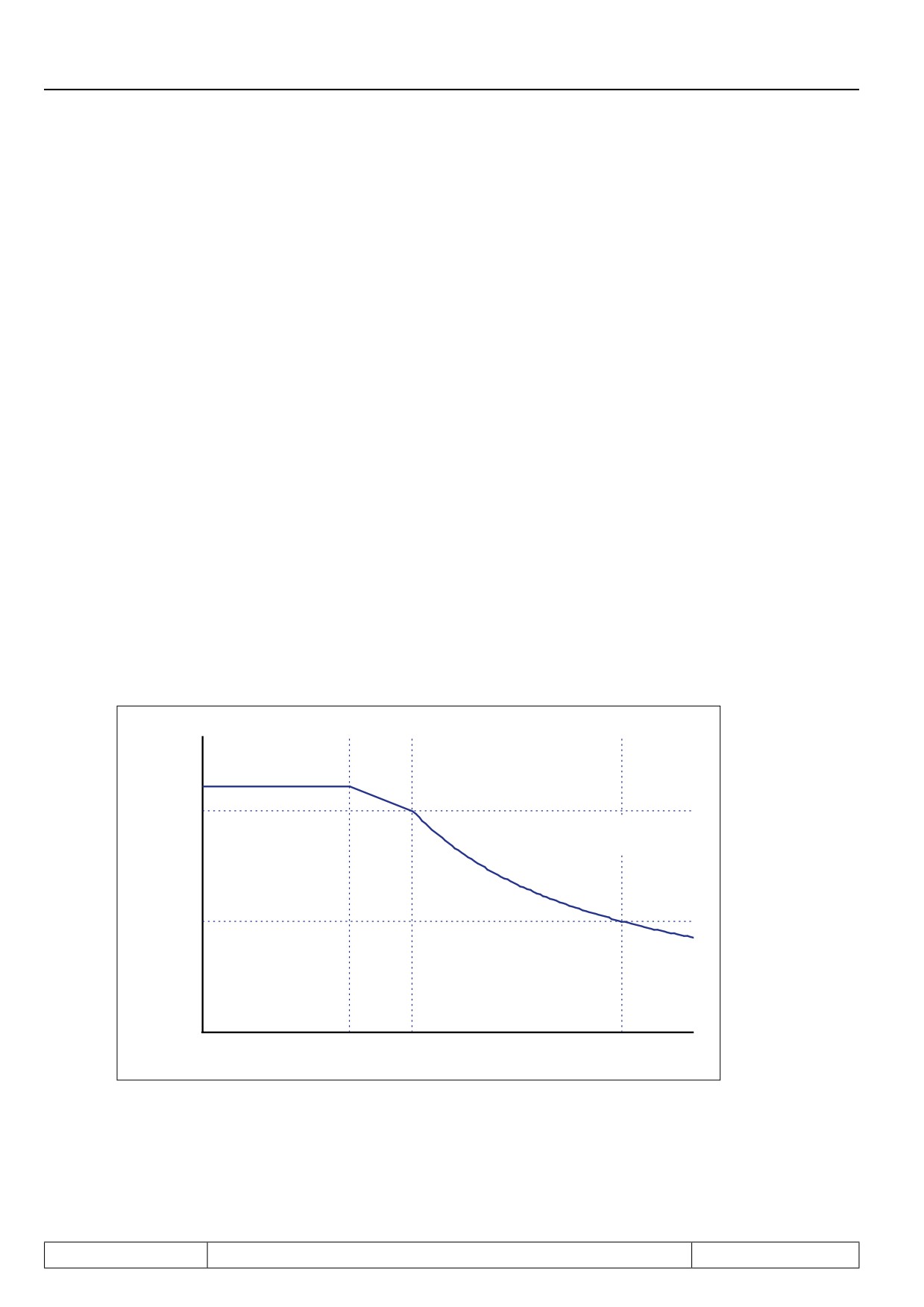
With the parameters dr.15...dr.18, the torque limiting characteristic is defined.
Figure 7.8.2.2a Field weakening range 1/x reduction
Torque [Nm]
dr.15
dr.16
1 / x reduction
ds.03 „Field weakening characteristic“ = 0: off
0,5 * dr.16
dr.17
dr.18
2 * dr.18
Actual frequency [rpm]
The "max. torque FI" (dr.15) depends on the maximum inverter current and cannot be changed.
In the default setting, the maximum torque in the field weakening range is lowered
- due to the flux reduction
- following a 1/x-function.
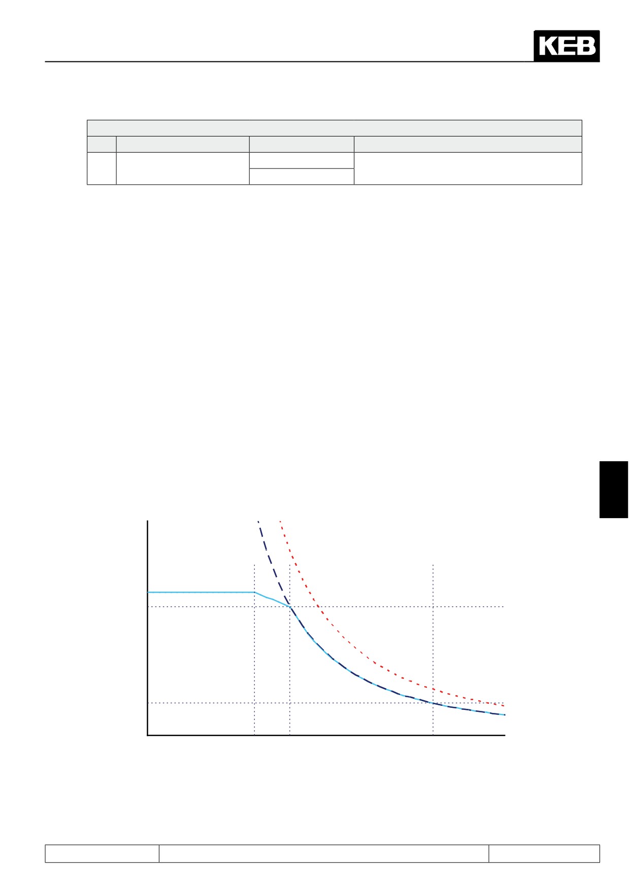
The physical breakdown torque characteristic of the motor is, however, a quadratic characteristic, i.e., the ma-
ximum active current in the field weakening range must also decrease.
If the motor is to be utilised up to its limits, the quadratic limiting characteristic must be activated. This occurs
via the value 2 in item "field weakening characteristic" of the parameter dS.03 "current/torque mode".
Page7.8 - 4
Torque Display and -Limiting
dS.03: Current / torque mode
Bit
Meaning
Value
Explanation
Field weakening characte-
0: off
Activation of the active current limitation in the
1
ristic
2: on
field-weakening range
With the parameter dr.16 "DASM max. torque corner speed" the limiting characteristic is adapted to the mo-
tor.
dr.16 = breakdown torque of the motor (at speed dr.18) - safety reserve
Example:
a motor shall have the following nominal properties:
Rated speed: 1470 rpm
Rated frequency = 50Hz
Rated torque: 36 Nm
Rated torque / breakdown torque = 2,5
chosen value for DASM field weakening speed (dr.18):
1500 rpm
Data sheets for breakdown torque of the motor at rated frequen-
2,5 * 36Nm = 90Nm
cy:
Safety reserve
25% = 22,5 Nm
dr.16 "'DASM max. torque corner speed" = 90Nm - 22.5Nm = 67.5Nm
The value of dr.16 can be greater than the value in dr.15, since the breakdown torque of the motor can be gre-
ater than the maximum torque of the inverter.
The safety factor is necessary because the limiting characteristic must be sufficiently far from the physical
breakdown torque of the motor.
Figure 7.8.2.2 b Field weakening range square reduction
7
Torque [Nm]
Square breakdown characteristic of
Square decrease
the motor
dr.03: „Field weakening cha-
racteristic“ = 1: on
dr.15
dr.16
0,25 * dr.16
Actual frequency [Hz]
dr.17
dr.18
2 * dr.18
Page7.8 - 5
Torque Display and -Limiting
7.8.3
Physical torque limits DSM
7.8.3.1Torque limits in the base speed range (dr.27, dr.15)
In parameter dr.27, the rated torque of the synchronous motor must be entered according to the name plate.
In dr.15, the maximum torque (limited by the maximum current of the inverter) is displayed.
With activated hardware current limit (uF.15 = 1 or 2), the maximum current is equal to the hardware current
level (In.18) minus a safety reserve of 5% of the inverter rated current.
With deactivated hardware current limit (uF.15 = 0), the maximum current is equal to the overcurrent error limit
minus a safety reserve of 10 %.
7.8.3.2Torque limits in the field weakening range
Normally, a synchronous motor is operated with a magnetising current = 0.
If the useable speed range has to be increased, one has to run it in the "field weakening range". In this range,
the maximum voltage controller provides a magnetising current that counteracts the pulse wheel voltage.
If the inverter malfunctions, one gets magnetising current = 0. The motor then feeds the pulse wheel voltage
back into the inverter. This voltage may maximally reach the overvoltage threshold, because otherwise the
inverter is damaged. Therefore, the permissible speed is limited. If the drive exceeds the value of parameter
ru.79 "abs. speed value (EMK)", the inverter gives an "error! excessive speed".
DSM EMK [Vpk * 1000rpm] (dr.26) x actual speed
Voltage of the magnet wheel =
——————————————————————
1000 rpm
Attention:
The advantage of the higher maximum speed is offset by several disadvantages:
-
the drive is more prone to vibrations in the base speed range
-
not all motors are suitable for field weakening operation
-
due to of the magnetisation current requirements, a higher current is needed for the same torque
-
the rotor position information must be exact. A system position error (e.g., due to inexact encoder moun-
ting) can render the drive uncontrollable.
Page7.8 - 6
Torque Display and -Limiting
7.8.3.2.1
Determination of the magnetising current limit (dS.13)
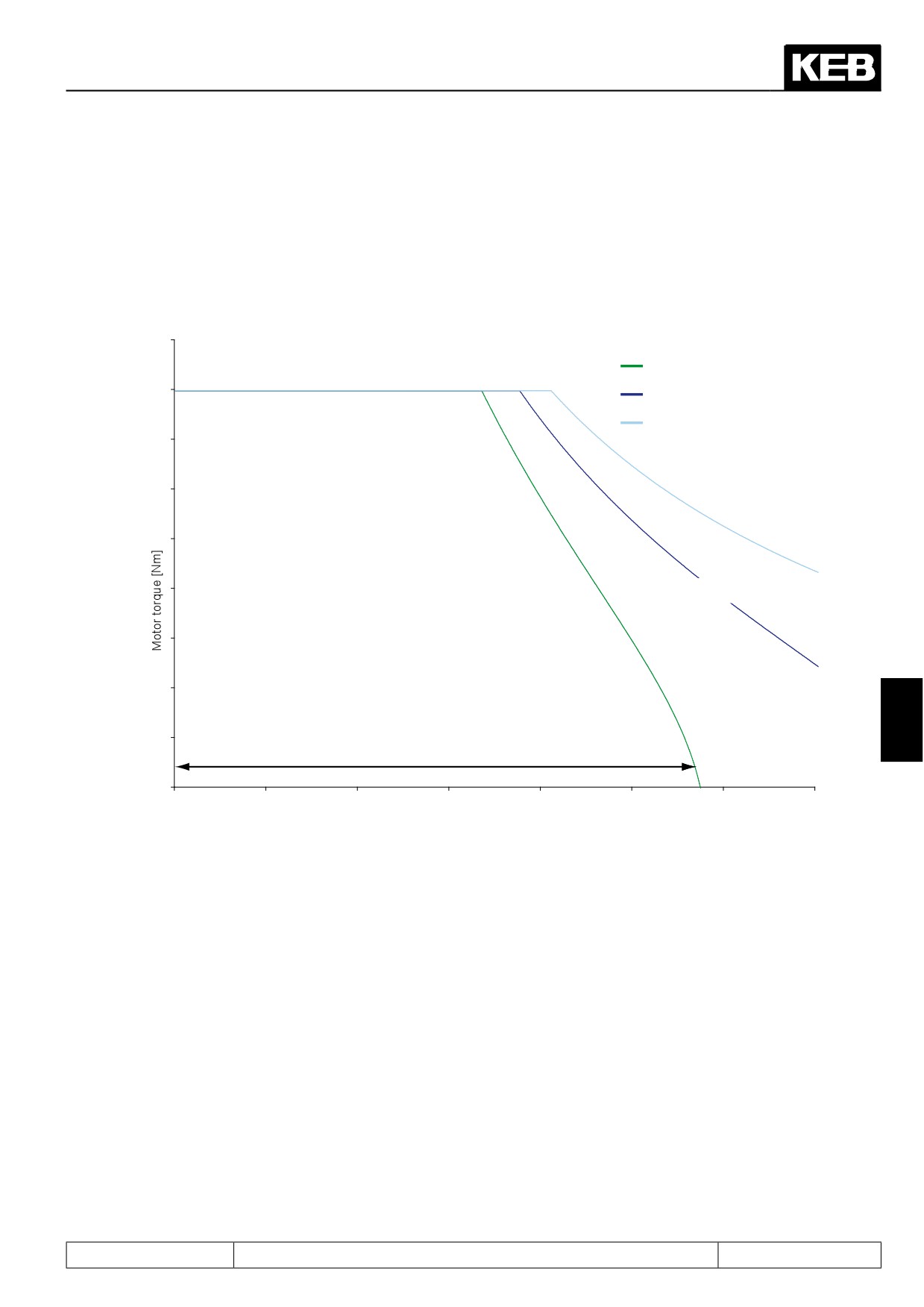
For every motor, a specific, ´ideal´ magnetising current limit exists. If the limit is set too low, the available field
weakening range is very small.
The following figure shows the relation between the maximum achievable torque and the magnetising current
limit dS.13.
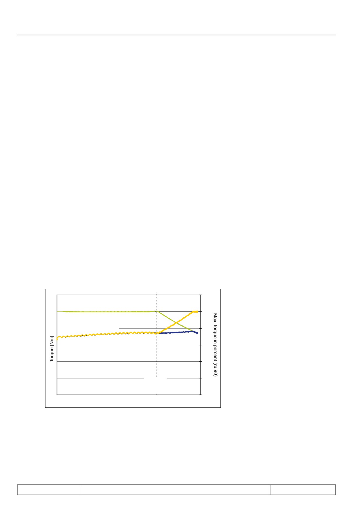
Figure 7.8.3.2.1a Magnetizing current limit
Torque (dS.13 = 0)
Torque (dS.13 = 0,5 * In)
Torque (dS.13 = In)
Field weakening range
7
Basic speed range
Speed [rpm]
Is the magnetising current limit set too high, the available torque decreases again. In addition, too high a value
for dS.13 can cause the maximum voltage controller to "hang". That means: for setting the magnetising current,
more voltage is used than is gained from the field weakening. The voltage, therefore, remains too high.
A typical value for dS.13 is the rated motor current. In the field weakening range, the current needed to set a
defined torque increases.
Page7.8 - 7

Torque Display and -Limiting
Figure 7.8.3.2.1b Limit current in the field weakening range
Start of the
“field weakening range“
Motor current [A]
Torque limit characteristic
Speed [rpm]
Attention:
To assure that the speed controller can control the drive, an active current must always be available that should
not fall below 0.5 x dS.13 .
It is necessary to pay attention to the appropriate settings for the torque limit and for the maximum current!
7.8.3.2.2
Definition of the limiting characteristic
Starting at a certain speed, the drive cannot provide the same torque in field weakening operation that it provi-
des in the base speed range.
If the drive is to accelerate at a constant torque limit (e.g., double the rated torque), the motor is (despite field
weakening) physically unable to provide this torque.
The set torque can also not be adjusted anymore and the drive ´hangs´ in the voltage limit (modulation factor
ru.42 = 100%). Therefore, a limiting characteristic that mirrors the physical limits of the drive must be given. this
limit depends on the dS.13 "magnetising current limit".
If no limiting characteristic is given, the user must insure that the motor is not asked to deliver an inadmissibly
high torque by choosing suitable acceleration /deceleration ramps and by appropriate selection of the load.
The parameters dr.33 and dr.39...47 are used to set the limiting characteristic.
Page7.8 - 8
Torque Display and -Limiting
Attention:
For the torque values of the limiting characteristic, the value 0 must never be chosen. Also, the torque at the
highest speed (i.e., the last point on the characteristic) should minimally be set to the following value:
Magnetising current limit (dS.13)
Mmin = 0,37 x
—————————————————
x DSM rated torque (dr.27)
DSM rated power(dr.32)
This value must never be fallen short of for the following reason:
A potential error in the position sensing leads to the magnetising current creating a torque in the field weake-
ning range. An error of 20° electrical causes an unwanted torque from the magnetising current of maximally:
Magnetizing current limit (dS.13)
M dS.13 = sin(20°) x
—————————————————
x DSM rated torque (dr.27)
DSM rated power (dr.32)
If this torque error cannot be compensated for due to the limiting characteristic, the drive becomes uncontrolla-
ble.
All other torque values must be chosen appropriately higher.
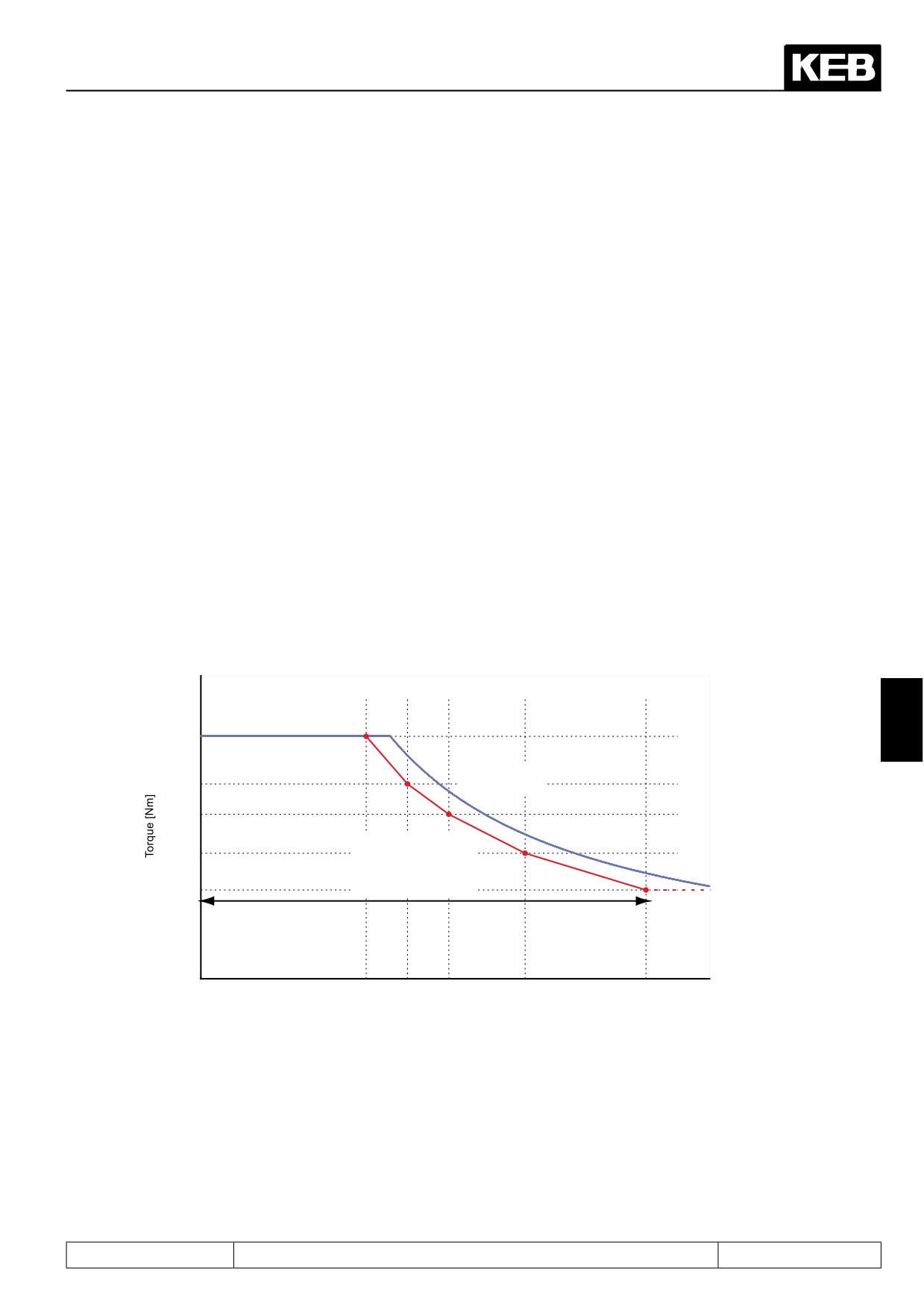
The parameters dr.33, 40, 42, 44, 46 contain the maximum torque for the speeds in dr.39, 41, 43, 45, 47. Va-
lues between these points are interpolated linearly.
Figure 7.8.3.2.2 Limiting characteristic
7
dr.33
Measured limiting
dr.40
characteristic
dr.42
dr.44
Inverter coded limiting
characteristic (with
safety distance!)
dr.46
Usable speed range
by the application
dr.39 dr.41 dr.43
dr.45
dr.47
Speed [rpm]
Page7.8 - 9
Torque Display and -Limiting
The limiting characteristic is activated via dS.03 bit 1.
dS.03: Current / torque mode
Bit
Meaning
Value
Explanation
Field weakening characte-
0: off
Activation of the limiting characteristic
1
ristic
2: on
(determined via dr.33, dr.40...47)
7.8.3.2.3
Shifting of the limiting characteristic
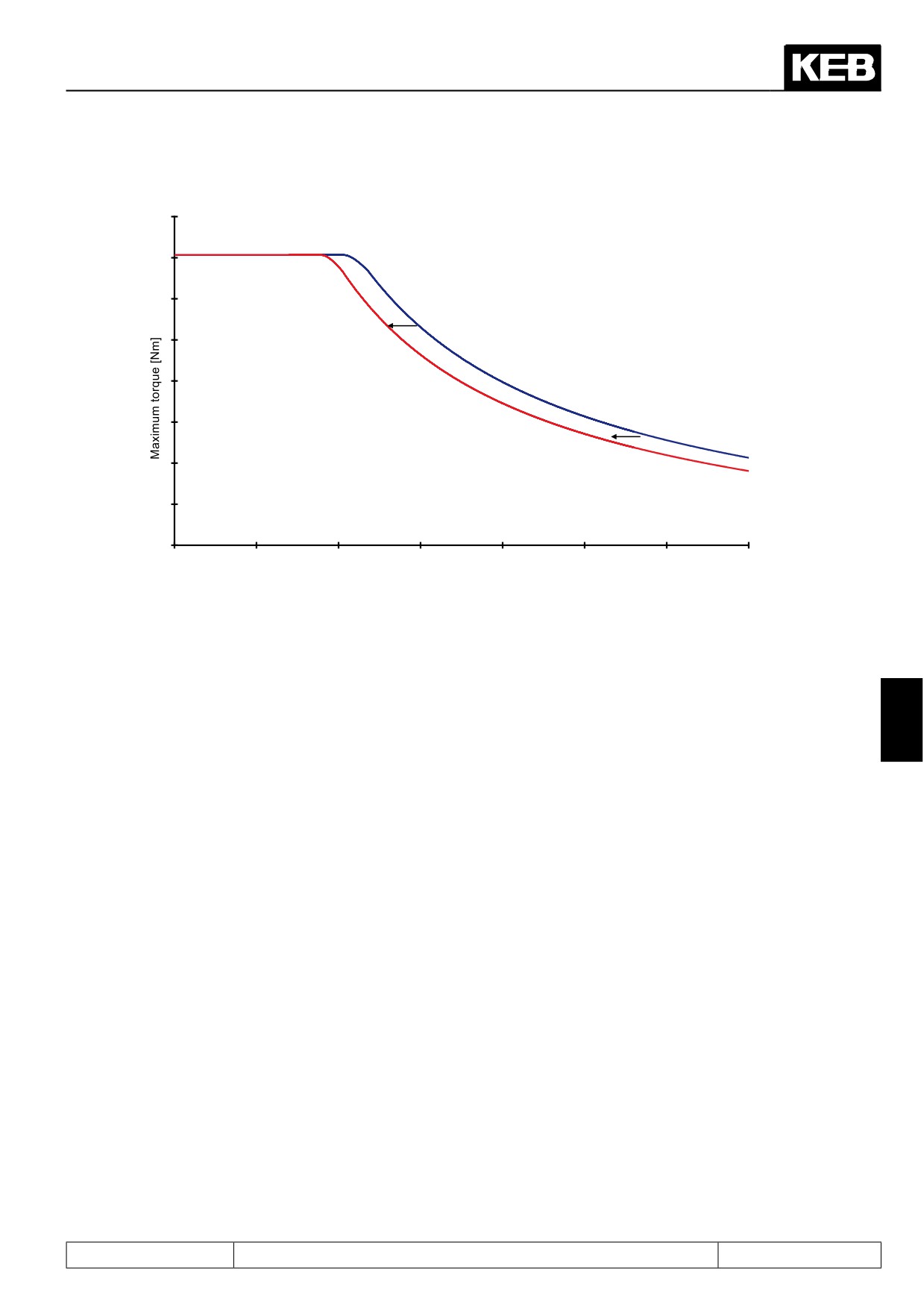
The physical torque limiting characteristic of the motor depends on the maximum output voltage of the inverter.
This is determined by the magnitude of the DC link voltage, which, in turn,depends on the mains input voltage
and the inverter load.
Therefore, different modes for the programmed limiting characteristic can be selected in dS.03 .
dS.03: Current / torque mode
Bit
Meaning
Value
Explanation
0: off
Shift generally not active
4: on
Shift generally active
8: >Un(FI) = off, ab-
Shift not active, if ZK voltage is greater than the no-
ZK dependent shift of the
normal stopping
=
2, 3
minal voltage (also for emergency stop)
characteristic (SM)
off
12:
>Un(FI)
= off,
Shift generally not active for emergency stop, other-
abnormal stopping
wise inactive if ZK voltage is greater than the nomi-
= on
nal voltage
The value 0 ("off") can be used if the limiting characteristic for the mains input voltage is programmed, the ma-
chine is operated with it, and this voltage is relatively constant.
The advantage (e.g., during ramp-up at the torque limit) is that the continuous, load-dependent fluctuations of
the intermediate circuit cannot cause any torque fluctuations.
If, however, the mains input voltage is variable (e.g., affected by other users), or if the mains voltage at the
location of the machine is unknown, dS.03 equal 4, 8 or 12 must be selected.
The programmed limiting characteristic is then always valid for the inverter rated voltage (400V or 230V) and is
adjusted proportionately to the voltage.
Page7.8 - 10
Torque Display and -Limiting
Figure 7.8.3.2.3 Shift of limiting characteristic
Maximum reachable torque at
400V power supply voltage
Maximum reachable torque at
360V power supply voltage
Speed [rpm]
The limiting characteristic must always be programmed beyond the speed range in which the motor is to be
operated later. Otherwise, the drive operates in an undefined range at lower DC link voltage values due to the
shift of the characteristic to lower speeds.
For value 4 ("on" ), the limiting characteristic is shifted in both directions, to lower speeds at lower voltage, and
to higher speeds at higher voltages.
7
At this value, the motor achieves maximum torque. A disadvantage is that the DC link voltage can rise quickly
and over a wide range, especially in generating operation. These dynamic changes can cause significant insta-
bility in the field weakening range.
Therefore, setting 8 (">Un(FI) = off, quick stop = off") is preferable. Here, only that shift of the characteristic
which is physically necessary because of insufficient DC link voltage is carried out.
I.e., the characteristic is shifted only if the DC link voltage is smaller than the rated DC link voltage (= √2 * in-
verter rated voltage).
If the DC link voltage is greater than the nominal voltage, no shift is applied.
The value 12 (">Un(FI)=off, quick stop=on") can be chosen if the maximum achievable torque should be availa-
ble for emergency stops. In this mode, the limiting characteristic is shifted to higher speeds at higher DC link
voltage only during emergency stop-operation. If possible, the value "8" should generally be selected.
Page7.8 - 11
Torque Display and -Limiting
7.8.3.2.4
Effect of the current limit
In the field weakening range, the total current of the motor is comprised of active current and magnetising cur-
rent. The maximum torque is limited only by the active current.
For some motors, the data sheet lists a maximum current. This applies to both components together. Therefore,
the total current can be limited by this parameter.
If both components together exceed the current limit, the magnetising current gets priority.
Attention:
To insure that the speed controller can control the drive, an active current must always be able to flow. The ma-
gnetising current limit (dS.13) must therefore always be significantly lower than the maximum current (dr.37). It
should maximally be dS.13 = 0,75 x dr.37.
The total current limit dr.37 is activated by bit 0 of the parameter dS.03.
dS.03: Current / torque mode
Bit
Meaning
Value
Explanation
max current
/
torque
0: off
software current limiting off
0
mode
1: on
software current limiting on
Page7.8 - 12
Torque Display and -Limiting
7.8.4
Setting of the application-dependent torque limits
For some applications, it is not desired to provide maximum possible torque, instead, the application requires
other, process-related limits(e.g., protection of mechanical components).
These can be set via parameters cS.19...cS.23. The torque limit characteristic defined via the maximum current
and the available voltage always remains active as a superimposed limit.
If only one limit is needed for all operating ranges (clockwise rotation, counter clockwise rotation, motoring and
generating), the parameter "absolute torque reference" (cS.19) can be used. All other limits (cS.20...cS.23)
must then have the value "-1:off".
If different torque limit are needed, they must be entered in the parameters cS.20...cS.23 (=torque limit for the
different operating ranges).
The torque limits can be changed during operation for special applications by multiplying them with a factor of
0..100%.
The parameter "torque reference source" (cS.15) determines how this factor is built for the adjusted torque
limits (cS.19...cS.23).
cS.15 Torque reference source
Value
Explanation
0: Analog REF
Parameter "selection Ref-input / Aux-function" (An.30 ) determines how the Ref- and
Aux-value,respectively, is calculated (see chapter 7.2). By default, AN1 is the Ref- and
1: analog Aux
AN2 is the Aux-value. As multiplier(s) for the torque limit(s), they are limited to 100%.
2: digital absolute
the torque limits (cS.19...cS.23) are not attenuated by a factor
(cS.19..23)
cS.18 (percentage torque reference) is the factor for the torque limits
3: digital % (cS.18)
(cS.19...cS.23)
4: Motorpoti
the base value of the motor potentiometer function (see chapter 7.15) is the factor for
(ru.37)
the torque limits (cS.19...cS.23)
7
the base value of the PID controller (see chapter 7.15) is the factor for the torque limits
5: external PID
(cS.19...cS.23)
output (ru.57)
The base value can be read out in ru.57
Analog input value AN2 is the factor for the torque limits (cS.19...cS.23). At this setting,
the analog input is scanned and processed on a faster grid. To implement the faster
6: AN2 direct
processing, the following parameters have no function: "AN2 noise filter" (An.11), "AN2
(+/- 10V)
offset Y" (An.17), "AN2 zero clamp" (An.14), "AN2 save mode" (An.12). The value of
AN2 is limited as a multiplier to 100%.
Example: cS.20 Torque limit forward motor = 20Nm
cS.21 Torque limit reverse motor = 20Nm
cS.22 Torque limit forward gen. = 15Nm
cS.22 Torque limit reverse gen. = 10Nm
cS.15 Torque reference source = 3: digital % (cS.18)
cS.18 Torque reference setting = 50%
Resulting torque limits
Clockwise rotati- motoring = 10Nm / generating = 7,5Nm
on:
Counter clock- motoring = 10Nm / generating = 5Nm
wise rotation:
These limits can be lowered more using the limiting characteristic.
Page7.8 - 13
Torque Display and -Limiting
7.8.5
Display of the actual torque values and limits
Parameters ru.11 and ru.12 show the current target and actual torque of the drive, respectively.
In ru.73 and ru.74, the torque in [%] with respect to the parameter "absolute torque reference" (cS.19) is dis-
played.
The active limits for the current direction of rotation can be read off in the parameters ru.47 "Act. torque limit
motor" and ru.48 "Act. torque limit generator". The parameters ru.47 and ru.48 depend on the programmed tor-
que limits, the limiting characteristic, and the current limits (e.g., hardware current limitation or dr.37 "maximum
current").
7.8.6
Display of the torque-related motor workload (ru.90)
With ru.90, the utilization of the whole drive can be displayed.
The calculation of ru.90 depends on the mode.
7.8.6.1Mode 1: "Reference torque" Le 27 = 0
The calculation of ru.90 then follows the formula:
Actual torque display (ru.12)
ru.90 =
———————————————————————
Set torque limit (ru.47motoring respectively ru.48generating)
Figure 7.8.6.1 LE.27 = 0
120
Act. torque limit mot. (ru.47)
100
Actual torque display (ru.12)
80
Max. torque in percent (ru.90)
60
40
DASM field
20
weakening
speed (dr.18)
0
Speed [rpm]
Page7.8 - 14
Torque Display and -Limiting
7.8.6.2Mode 2: "Reference torque" Le 27 unequal 0
The maximum thermally permissible torque - i.e., in the base speed range, the rated torque, and the range
higher than the rated speed, the rated torque attenuated following a 1/x-function - is taken as 100% utilization
of the motor.
The programmed speed-torque characteristic is taken as 100% utilization of the inverter. This is comprised of
the torque limit in the cS-parameters (e.g., cS.19 ) and the limiting characteristic in the dr-parameters (e.g.,
dr.15...dr.18).
The value set in parameter "reference torque" (LE.27) corresponds to 100% utilization in the application. This
could be, e.g., the permanently permissible torque for the attached screw conveyor or gear.
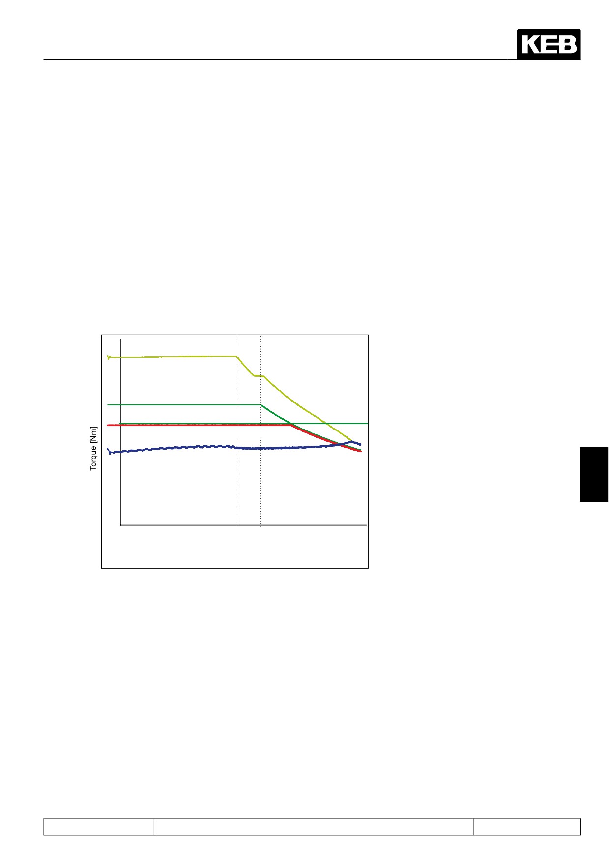
The smallest of the 3 values indicates the torque with which the whole drive can be loaded permanently at the
corresponding speed.This torque is the reference torque for the calculation of the parameter "max torque in %"
(ru.90).
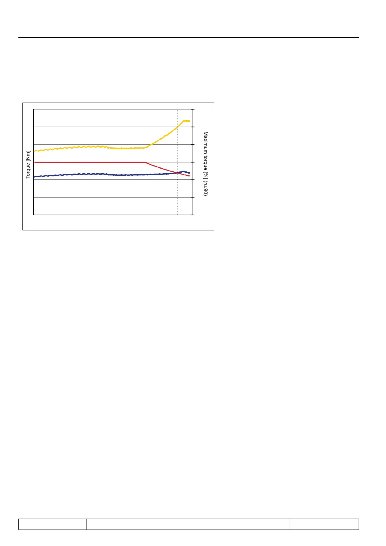
Figure 7.8.6.2a LE.27 ≠ 0 Reference torque
Actual torque limit mot. (ru.47)
Continous torque (S1 operation)
Reference torque (le.27)
Reference torque for max. torque in % (ru.90)
Actual torque display (ru.12)
7
Field
Rated
weakening
speed
speed (dr.18) (dr.01)
Page7.8 - 15
Torque Display and -Limiting
ru.90 is calculated as follows:
Figure 7.8.6.2b Display ru.90
120
100
Max. torque in percent (ru.90)
80
Reference torque for max. torque in percent (ru.90)
60
Actual torque display
(ru.12)
Actual torque display (ru.12)
40
ru.90 =
———————————
Reference torque for ru.90
20
0
Speed [rpm]
Page7.8 - 16
Torque Control
7.1
Operating and appliance data
1.
Introduction
7.2
Analog in- and outputs I
2.
Summary
7.3
Digital in- and outputs
3.
Hardware
7.4
Setpoint-, rotation- and ramp adjustment
Motor data and controller adjustments of the asynchronous
7.5
4.
Operation
motor
Motor data and controller adjustments of the synchronous
7.6
motor
Selection of Operating
5.
Mode
7.7
Speed control
6.
Initial Start-up
7.8
Torque display and -limiting
7.9
Torque control
7.
Functions
7
7.10
Current control, -limiting and switching frequencies
8.
Error Assistance
7.11
Speed measurement
9.
Project Design
7.12
Positioning and synchronous control
7.13
Protective functions
10. Networks
7.14
Parameter sets
11. Parameter Overview
7.15
Special functions
12. Annex
7.16
CP-Parameter definition
Page7.9 - 1
Torque Control
7.9.1.
Torque reference source
7.9 - 3
7.9.2.
Rate of change torque reference
7.9 - 3
7.9.3.
Speed calculation
7.9 - 4
7.9.4.
Control mode
7.9 - 4
7.9.4.1
Mode 1: torque-controlled operation with emergency switching to
speed control
7.9 - 4
7.9.4.2
Mode 2: torque-controlled operation with superimposed speed control
7.9 - 5
Page7.9 - 2
Torque Control
7.9
Torque control
In torque-controlled operation, the user directly specifies the torque the motor is to deliver, until the speed target
value is reached.
7.9.1. Torque reference source
The set torque is calculated from the value in parameter cS.19 multiplied by a factor (0..100%) that can be
taken from various sources (analog inputs, motor potentiometer, etc.). The torque setpoint source is selected
with parameter cS.15.
cS.15 Torque reference source
Value
Explanation
0: Analog REF
Parameter "selection Ref-input / Aux-function" (An.30 ) determines how the Ref- and
Aux-value, respectively, is calculated (see chapter 7.2). By default, AN1 is the Ref- and
1: analog Aux
AN2 the Aux-value. As a multiplier for cS.19, they are limited to 100%.
2: digital absolute
the value in cS.19 directly provides the torque reference
(cS.19..23)
3: digital % (cS.18)
cS.18 is the factor for cS.19
4: Motorpoti
the base value of the motor potentiometer function (see chapter 7.15) serves as the
(ru.37)
factor for the torque limit (cS.19..cS.23)
5: external PID
the base value of the PID controller (see chapter 7.15) is the factor for cS.19
output (ru.57)
The base value can be read off of ru.57
The analog input value AN2 is the factor for cS.19.
At this setting, the analog input is scanned and processed on a faster grid. To imple-
6: AN2 direct
ment the faster processing, the following parameters have no function: "AN2 noise
7
(+/- 10V)
filter" (An.11), "AN2 offset Y" (An.17), "AN2 zero clamp" (An..14), "AN2 save mode"
(An.12).
The value of AN2 is limited as a multiplier to 100%.
The overriding torque limitations, like "max. torque FI" (dr.15) remain in effect.
7.9.2. Rate of change torque reference
With cS.16 the rate of change of the torque reference can be limited.
cS.16: Torque acceleration time
Value
Explanation
0: off
torque reference is applied directly without ramp
The maximum rate of change for the torque reference equals the motor-rated torque
1..60000 ms
per adjusted ramp time (CS.16).
Page7.9 - 3