KEB COMBIVERT F5-A,-E,-H 4.0. APPLICATION MANUAL (2008) - page 16
Positioning and Synchronous Control
7.12.3.8
Angular correction
With parameter PS.04, an angle offset between master and slave can be created or eliminated in synchronous
operation.
With the positive edge of the input selected in parameter PS.03 "shift. slave input selection", a positive adjust-
ment is triggered.
The value of PS.04 is added to the master position, i.e.,:
ru.56 "set position" (corrected) = ru56 "set position" + PS.04
With the positive edge of the input selected in parameter PS.10 "shift. slave inverse input selection", a negative
adjustment is triggered.
The value of PS.04 is subtracted from the master position, i.e.,:
ru.56 "set position" (corrected) = ru.56 set position - PS.04
The value of PS.04 can be positive or negative.
The adjustment is always made with the synchronisation via ramps (see item 7.12.3.5.4), to avoid torque sur-
ges in the drive. The treatment of the switching condition "drive running synchronously" corresponds to the
behaviour during initial synchronisation with ramps.
The angle adjustment can, e.g., be used to align master and slave after the approach to reference point in the
inching mode.
Page7.12 - 24
Positioning and Synchronous Control
7.12.3.9
Angular reset
An input can be defined via the parameter "reset master/slave difference input selection" (ps.11) that sets the
current angle difference between master and slave to zero.
At the rising edge of the input, the master position (= ru.56 "set point position") is set equal to the slave positi-
on (= ru.54 "actual position"). Resetting the angle adjustment is done without ramps. The switching condition
"drive running synchronously" remains set.
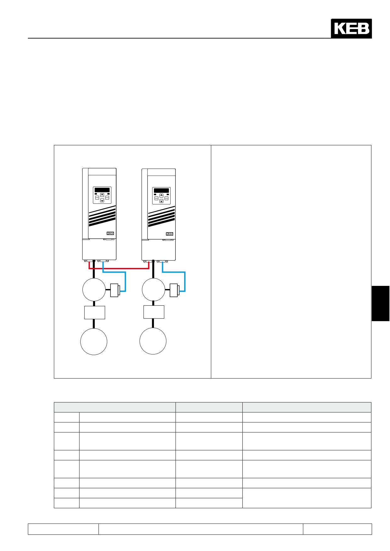
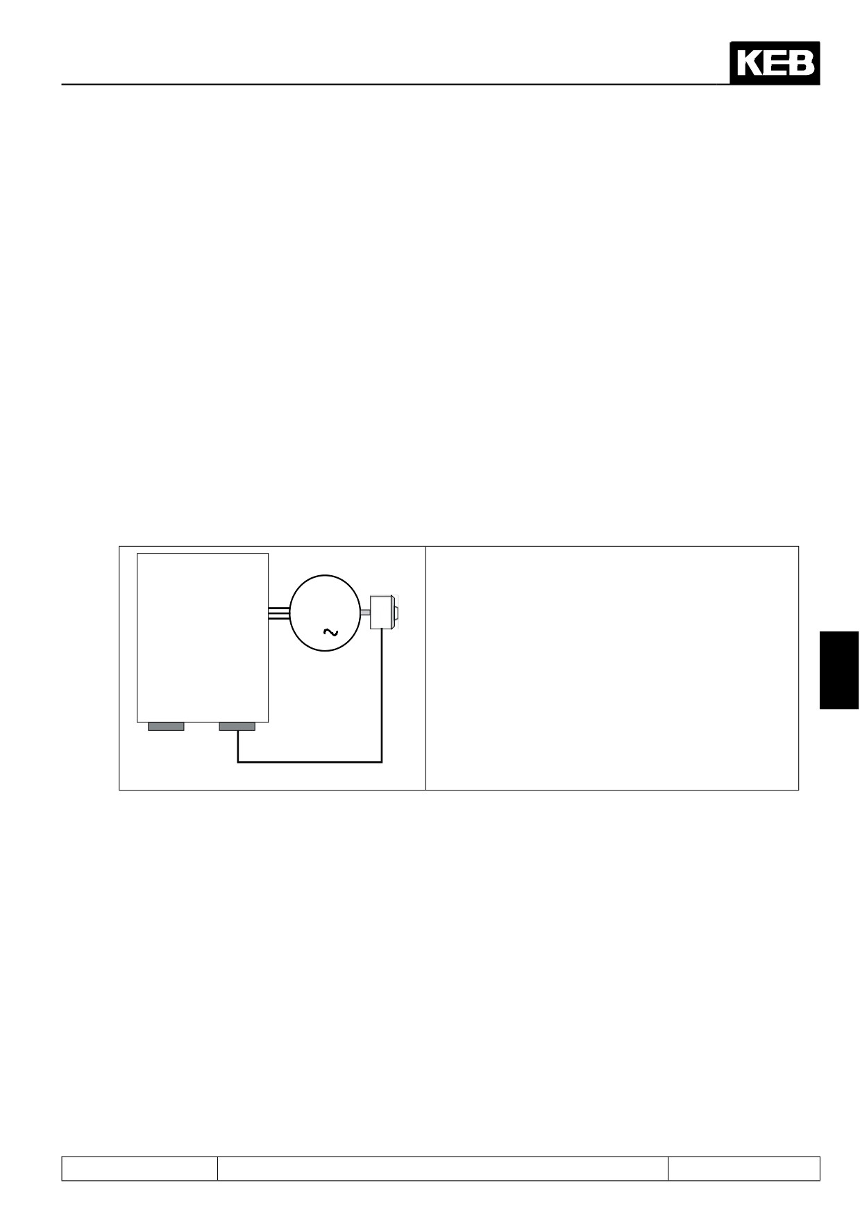
Example of a printing press:
Slave
Master
An F5-S serves as master shaft.
X3B of the master is incremental encoder output.
The incremental encoder analogue provides 2048 in-
crements per revolution.
ENTER
START
FUNC.
START
F/R
SPEED
ENTERF/R
FUNC.SPEED
STOP
STOP
The master transmission has a gear ratio of 15 to 1.
An F5-S serves as slave.
X3B of the slave is incremental encoder input.
The slave transmission has a gear ratio of 5 to 1.
ANTRIEBSTECHNI K
ANTRIEBSTECHNI K
X3B X3A
X3B X3A
3
3
~
~
7
i= 5
i= 15
Slave
Master
Direction of
Direction of
rotation clock-
rotation counter-
wise
clockwise
Parameter list for the slave shaft:
Parameter
Value
Notice
cs.00
Speed control configuration
4: vector controlled
cs.01
Actual source
0: Channel 1
Speed feedback is channel 1
1: Synchronous
PS.00
Posi-/Synchronous mode
mode
PS.01
Act. master source
1: Channel 2
Master position via channel 2
Synchronous running active, as soon as
PS.02
Posi / synch input selection
1: ST (X2A.16)
control release is given
PS.06
KP pos/syn
100
Kp unequal 0 => angular-synchronous
Ec.14
Gear 2 numerator
5
Slave / master gear
Ec.15
Gear 2 denominator
15
Page7.12 - 25
Positioning and Synchronous Control
7.12.4Posi mode
7.12.4.1
Selection of operating mode
The positioning module contain two operating modes:
-
"positioning mode" (chapter 7.12.4) with its sub-functions
- Single positioning
- Sequential positioning (sequence control system)
- Rotary table positioning
- defined stop
- Remaining distance positioning
- Flying Referencing
-
"Contouring control" (chapter 7.12.5)
The operating mode is selected via parameter PS.00 bit 0...2.
PS.00: Posi-/Synchronous mode
Bit
Meaning
Value
Explanation
0...4
Without function for positioning
5: Posi mode
Selection of operating mode "positioning mode"
6: Contouring con-
Selection of operating mode "contouring control"
0...2
Posi-/Synchronous mode
trol
The operating modes (synchronous running, po-
7: Via control word
sitioning mode or contouring control) are selected
via the control word (Sy.43 or Sy.50).
The positioning module must be activated by an input. The input is selected in parameter PS.02 "Posi/Sync.
input selection".
7.12.4.2
Posi mode / principle
In the positioning mode, the drive can approach a single position or sequences of positions can be programmed
that are reached consecutively, and, respectively, are passed through with a defined speed.
Up to 32 positions can be stored in the inverter. For every position, a maximum profile speed can be program-
med.
To be able to report various operating condition (e.g., positioning active, target reached) to an overriding con-
trol, specific progress messages and switching conditions exist for the digital outputs.
The drive can be adapted to the application very flexibly because a great variety of responses can be program-
med. For a new target set during a running positioning one can, e.g., choose between:
● do not allow generally
● allow only in certain actual position range
● allow only if the new target can be reached with the adjusted ramps
● allow even if the drive first overshoots the new target, reverses, and then reaches the target
● etc.
The response to errors can be similarly flexible.
Page7.12 - 26
Positioning and Synchronous Control
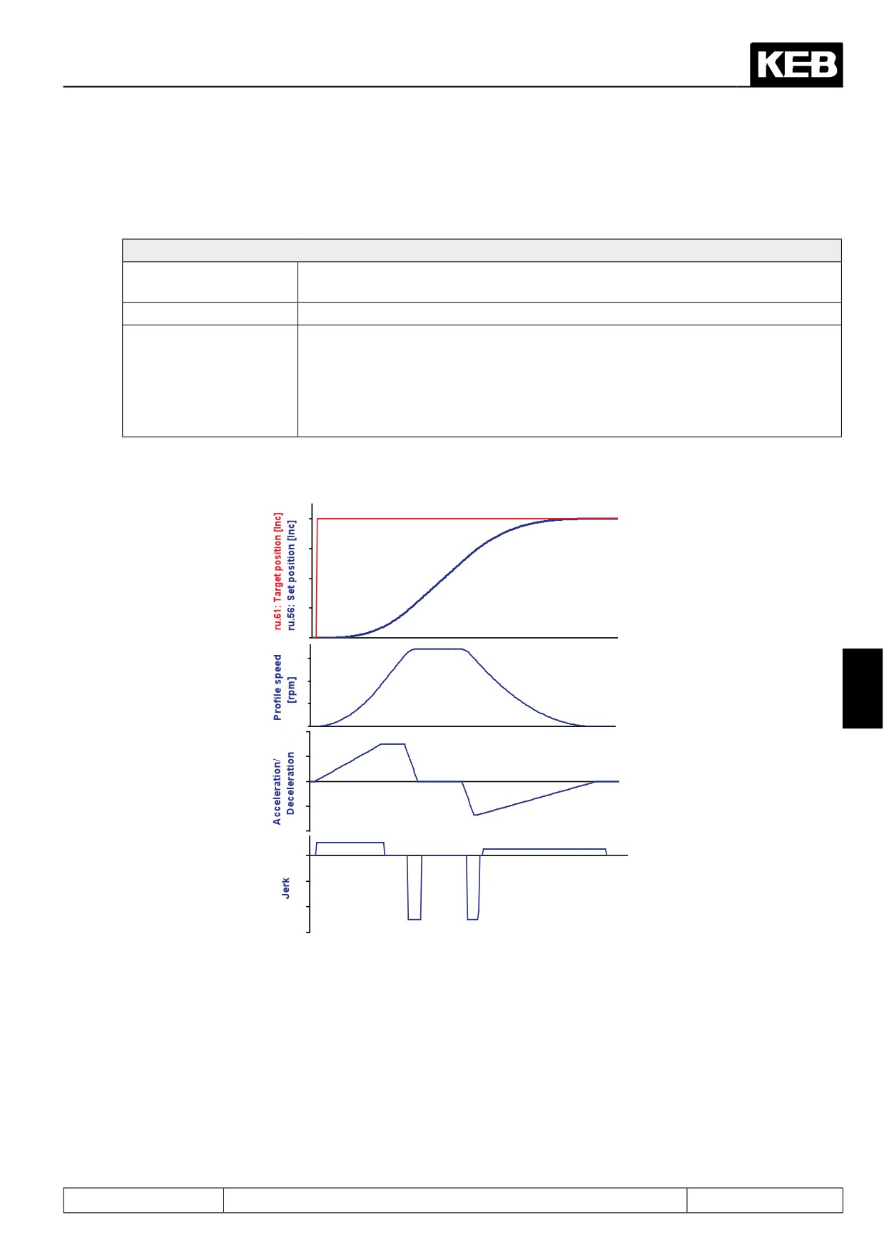
During every positioning, the inverter calculates a speed and position that the drive
should have at that time, in 1ms-cycles, to reach the target in compliance with all settings. This is the so-called
speed / position profile.
Settings
Maximum acceleration /
Defined by acceleration / deceleration time (oP.28...oP.31)
deceleration
Maximum jerk
Defined by S-curve times (oP.32...oP.35 and oP.70...oP.73)
= ru.63 "profile speed" + PS.09 "posi/ syn position limit.
The profile speed is either PS.25 "index speed" or PS.31 "max. speed setting %"
Maximum speed during
* oP.10 "max. reference forward" (dependent on PS.00/ bit 4). The speed limits
positioning
oP.10 / oP.11 "max. reference" do not act as setpoint limits anymore. oP.14 / oP.15
"abs. max. reference" remains operative. The error "speed limit exceeded" is trig-
gered when crossing the trigger level oP.40 / oP41.
That results in the following example behaviour of position, speed, acceleration, and jolt:
7
Time
If the drive cannot follow the position profile (e.g., due to reaching the torque limits), the position controller
intervenes and changes the setpoint speed with respect to the profile speed. Thereby it is possible that the
programmed values for maximum acceleration / deceleration and maximum jolt are exceeded.
Page7.12 - 27
Positioning and Synchronous Control
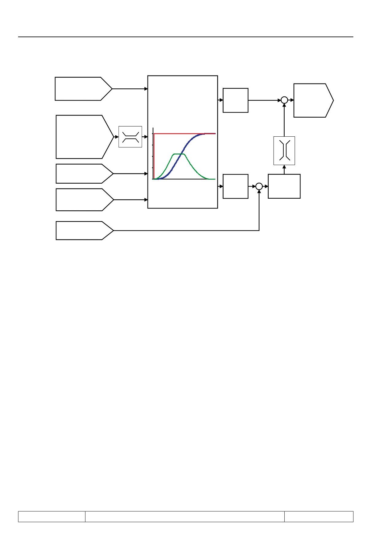
PS.24
Profile calculation
ru.02
Index position
ru.61: Target position [Inc]
Ramp output
(=ru.61) target position
Profile
oP.14
ru.56: Set position [Inc]
display
speed
abs. max. refe-
Profile speed [rpm]
+
(setpoint speed for
+
rence forward
speed controller)
PS.25
Index speed
in % of oP.10
PS.09
position limit
Posi/synchronous
oP.28..31
Acceleration /
deceleration time
ru.56
PS.06..PS.08
Set position
Position
+
-
oP.32..35 and oP.70..73
controller
S-curve times
(jerk limitation)
ru.54
Actual position
7.12.4.3
Posi mode / premise
To activate the positioning module, the following conditions must be met:
-
Start-up in the vector controlled operation must be completed successfully.
-
The position feedback must be defined (in PS.01 "act. master source", select the appropriate enco-
der interface and make the adjustments required for the encoder type in the Ec-parameters).
-
An input for the activation of the positioning module must be defined (PS.02 "positioning / synchro-
nous input selection").
-
If hardware limit switches are to be used, two inputs must be programmed with the functions "32: for-
ward" and "64: backward" and be wired with the hardware limit switches. Additionally, the protection
function in Pn.07 "Proh. rotation stopping mode" must be activated.
-
If an absolute position reference is required, a reference point switch must be wired and an ap-
proach to reference point must be executed or an absolute encoder for the position feedback must
be used.
-
It must be defined how the positioning is to be started (e.g., digital input, selectable via PS.29: "start
positioning input selection" or control word).
-
The value for the position controller (PS.06 "KP for positioning / synchronous") must be set to a small
value for the start-up to avoid vibrations. If the basic start-up has completed successfully, the position
controller must be adjusted application-specific.
Note: after activation of the positioning module, the drive remains in vector controlled operation until the first
"start positioning" command has been executed. Parameter ru.00 shows, with the progress message "121:
ready for positioning", that the positioning mode has been activated. The drive, though, only enters position
controlled operation after the first "start positioning". The position controlled operation is ended as soon as the
positioning module is deactivated.
Page7.12 - 28
Positioning and Synchronous Control
7.12.4.4
Position normalisation
The resolution of the position display/ setting is done in increments and depends on the encoder system
used.
The following cases must be distinguished:
7.12.4.4.1
Position control by the motor encoder
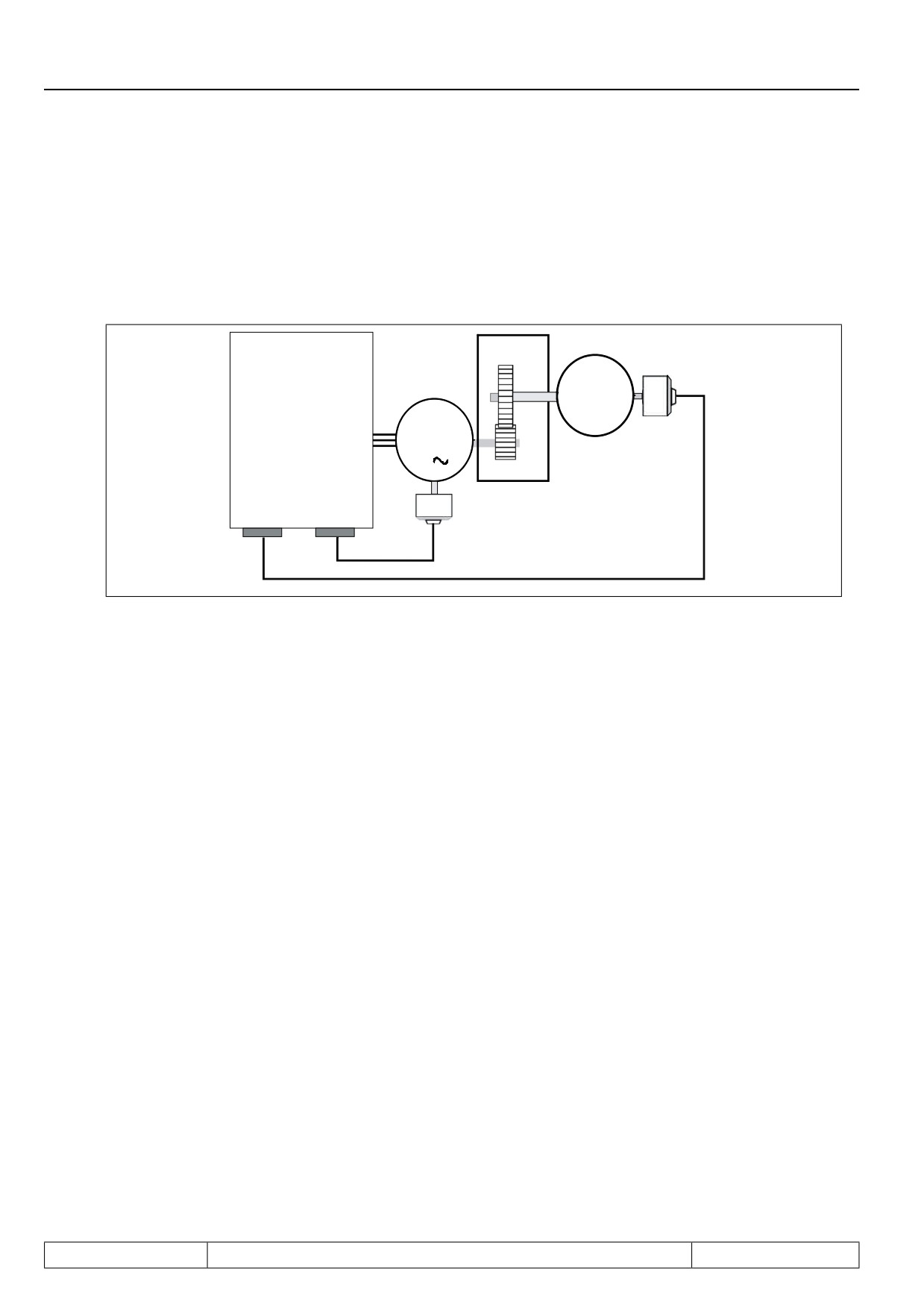
Position control is based on the motor position encoder. I.e., the position values refer to the motor position.
The number of increments per motor revolution amounts to "encoder increments per revolution" x 2 "multiple
evaluation"
If encoder interface 1 (X3A) is used, Ec.01 "encoder 1 (inc/r)" and Ec.07 "encoder 1 trigger" must be used for
the calculation.
If encoder interface 2 (X3B) is used, the number of increments per motor revolution must be calculated corre-
spondingly from Ec.11 "encoder 2 (inc/r)" and Ec.17 "encoder 2 trigger".
If the position control is done directly on the motor encoder, the same encoder channel must be selected in
PS.01 "act. master source" and cS.01 "actual source".
For the gear factor, the value 1 (d. h. gear factor numerator = gear factor denominator) must be selected.
Example:
Inverter
F5A-S
Let an incremental encoder with 2500 increments be
or
connected to encoder channel 1.
M
F5A-M
The motor shall travel 5.5 revolutions
3
Revolution in increments:
7
X3B
X3A
cS.01 = PS.01 = 0: Channel 1
Encoder
Encoder
Ec.04 = Ec.05 = 1000 default value
channel 2
channel 1
Ec.01 = 2500 increments per revolution
Ec.07 = 2: 4-fold evaluation
→ 2500 x 22 x 5,5 = 55000 increments
Page7.12 - 29
Positioning and Synchronous Control
7.12.4.4.2
Positioning by the output
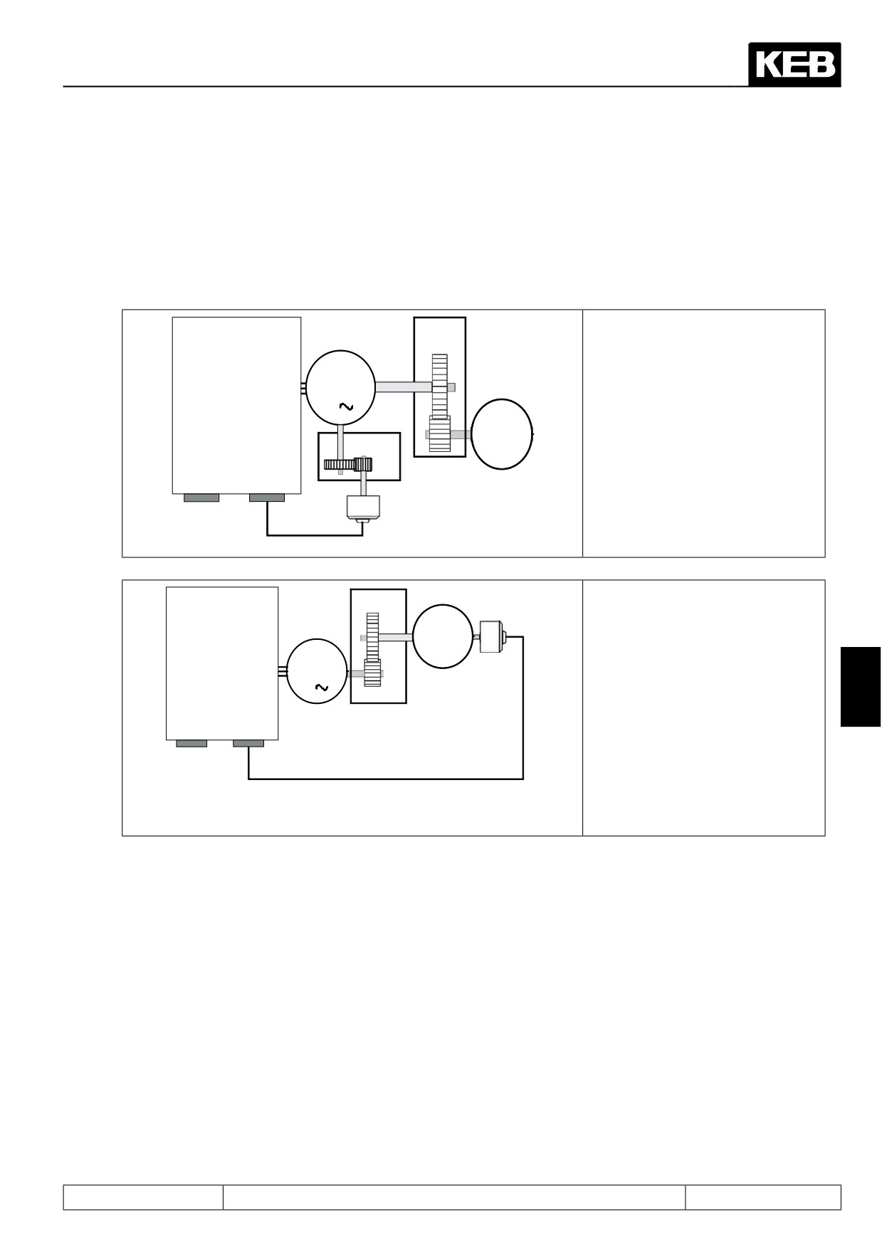
The position control is done directly on the value of the output encoder. I.e., the position values refer to
the position of the load.
Number of increments per load revolution = "encoder increments per revolution" (output encoder) x 2 "multiple
evaluation"
. Typically, the encoder interface 1 (X3A) is used for the motor position encoder and the encoder
interface 2 (X3B) for the output encoder.
Inverter
Gear
Output shaft
encoder
F5A-S
or
1
Load
F5A-M
M
3
3
X3B
X3A
Encoder
Encoder
Motor
channel 2
channel 1
encoder
To allow calculation of the speed precontrol profile for the speed control, the gear factor
between motor and load must be known, to convert the precontrol profile to the motor speed.
The speed limits and the values for maximum profile speed (PS.25) and maximum position control effect
(PS.09) refer to the motor speed.
Example:
Encoder channel 1: Incremental encoder with 2500 increments per revolution
Encoder channel 2: SSI encoder multiturn with 12bit resolution per revolution and 12bit multiturn
Gear ratio:
3 motor revolutions cause 1 load revolution
cS.01: Actual source
= 0
Channel 1
Ec.01: Encoder 1 (inc/r)
= 2500
Line number
Ec.07: Enc. 1 trigger
= 2
4-fold evaluation
PS.01: Act. master source
= 1
Channel 2
Ec.11: Encoder 2 (inc/r)
= 1024
12 bit resolution per revolution
Ec.17: Enc. 2 trigger
= 2
Ec.21: SSI Multiturn-resolution
= 12
12 bit Multiturn-resolution
Ec.14: Gear 2 numerator
= 3000
Gear factor =3
Ec.15: Gear 2 denominator
= 1000
The load shall travel 5.5 revolutions:
1024 x 22 x 5,5 = 22.528 increments
Page7.12 - 30
Positioning and Synchronous Control
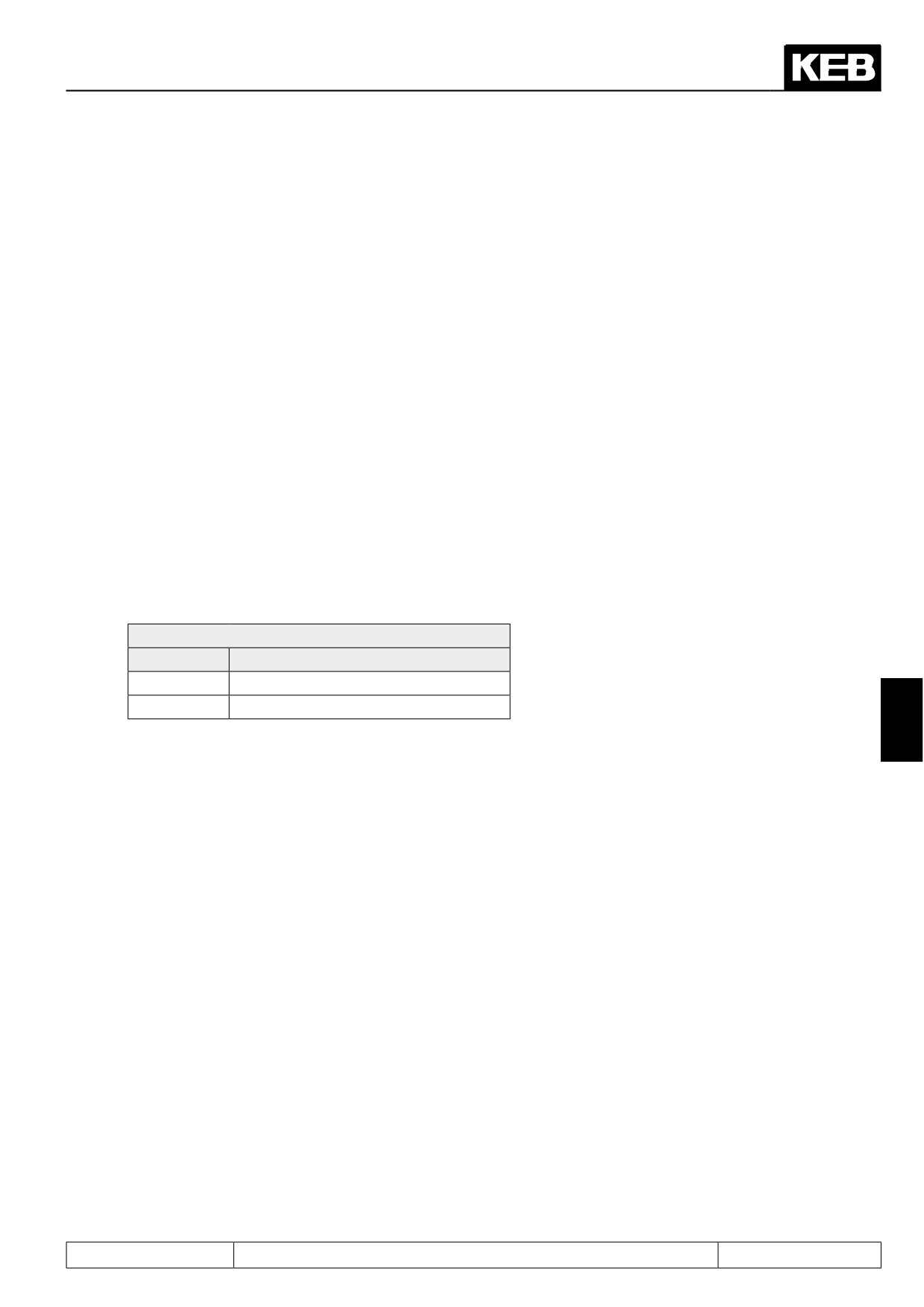
7.12.4.4.3
Speed and position control by motor encoder/ encoder mounting via gear
Attachment of the encoder for speed control by a gear is not ideal, since the gear backlash and
the gear ratio of gear 1 affect the control quality and dynamic of the speed controller (and of the
overlaid position control, too).
Two reasons can make this set-up necessary:
Application 1:
Inverter
Gear
2
F5A-S
Directly mounting the encoder to
or
the motor is not possible for me-
F5A-M
M
chanical reasons.
3
Referencing the load position is not
Load
Gear 1
possible.
X3B
X3A
Encoder
Encoder
channel 2
channel 1
Motor
encoder
Application 2:
Inverter
Gear
Output shaft
encoder
F5A-S
One wants to run with only one en-
or
Load
F5A-M
coder which must be installed be-
hind the gear for reasons of positio-
M
ning accuracy.
3
7
X3B
X3A
Encoder
Encoder
channel 2
channel 1
If synchronous motors are to be operated in this set-up, it must be ensured that the gear ratio is < 1 and the
value of pole-pair number x gear factor is integer.
Example:
3 encoder revolutions correspond to one motor revolution
Pole-pair number
= 15
→ Gear factor = 1/3 = 0,333
Page7.12 - 31
Positioning and Synchronous Control
15
→ pole-pair number x gear factor =
= 5 = whole-
→ synchronous motor operation
———
numbered possible
3
The number the increments per motor revolution is calculated as:
"encoder increments per revolution" * 2 "multiple evaluation" x "gear factor denominator" / "gear factor nume-
rator"
The number of increments per load revolution for application 2 is equal to:
"encoder increments per revolution" * 2 "multiple evaluation".
The encoder should always be connected to channel 1, since the software for this channel optimally supports
the motor encoder connection via gear. The parameter Ec.39 "encoder 1 over transmission" must be set to the
value "1: motor encoder". (For further functions and settings of Ec.39 see chapter 7.11)
Example (application 1):
Encoder channel 1: Encoder with 32 SIN / COS signals per revolution
Gear ratio:
Motor to encoder = 3 encoder revolutions correspond to motor revolution = 1 to 3
cS.01: Actual source (= PS.01)
= 0
Channel 1
Ec.01: Encoder 1 (inc/r)
= 32
number SIN / COS signals
Ec.07: Enc. 1 trigger
= 9
512-fold evaluation of the analog tracks
Ec.04: Gear 1 numerator
= 1000
Gear factor 0,333
Ec.05: Gear 1 denominator
= 3000
Ec.39: Encoder 1 over transmission
= 1
Encoder mounting via gear
The motor shall travel 5.5 revolutions
→ 32 x 29 x 3000 / 1000 x 5,5 = 270336 increments
Example (application 2):
Encoder channel 1: SSI encoder multiturn with 12bit resolution per revolution and 12bit multiturn
Gear ratio:
Motor to encoder = 5 motor revolutions correspond to motor revolution = 5 to 1
cS.01: Actual source (= PS.01)
= 0
Channel 1
Ec.01: Encoder 1 (inc/r)
= 1024
12-bit resolution per revolution
Ec.07: Enc. 1 trigger
= 2
Multiple evaluation with SSI encoder always = 2
Ec.53
Encoder 1 SSI multiturn res.
= 12
12 bit Multiturn-resolution
Ec.04: Gear 1 numerator
= 1000
Gear factor 0,333
Ec.05: Gear 1 denominator
= 3000
Page7.12 - 32
Positioning and Synchronous Control
Ec.39: Encoder 1 over transmission
= 1
Encoder mounting via gear
The load shall travel 5.5 revolutions:
→ 1024 x 22 x 5,5 = 22628 increments
If the parameter Ec.39: encoder 1 over transmission is set to "0: off", the inverter is compatible with
older software versions that do not yet include Ec.39.
The operation of synchronous motors is not supported and the position normalisation is as follows:
The number the increments per motor revolution is calculated as:
"encoder increments per revolution" x 2 "multiple evaluation"
The number of increments per load revolution for application 2 is equal to:
"encoder increments per revolution" x 2 "multiple evaluation" x "gear factor numerator" / "gear factor denomi-
nator"
With Ec.39 = 0 (=off), therefore, the meaning of the position display and setting (the position normalisation) is
changed.
7.12.4.5
Posi mode / actual position
The encoder interface for the feedback of the position control is adjusted via PS.01.
PS.01 Act. master source
Value
Function
0: Channel 1
Encoder channel 1 (X3A)
1: Channel 2
Encoder channel 2 (X3B)
7
If this channel is selected in parameter PS.00 "positioning / synchronous mode", the actual position (ru.54) is
taken from the encoder channel that is set in "act. master source" PS.01. This also applies if the positioning
module is not activated (i.e., the input selected in PS.02 is not set).
If the positioning mode is deactivated in PS.00 , the actual position of the encoder channel set in "actual source"
cS.01 is evaluated.
To obtain a reference point for the actual position of speed sensors without absolute position information (e.g.,
incremental encoder), an approach to reference point must be executed (see chapter 7.12.2).
This determines which mechanical position, e.g., should be related to the value 0 in parameter ru.54 "actual
position".
7.12.4.6
Posi mode / set and target position
In positioning mode, there are two parameters that provide information about the set point position:
Parameter ru.61 "target position" shows the target position for the running positioning, i.e., the position the drive
should have reached at the end of the positioning.
Parameter ru.56 "set position" displays the position the drive should have reached currently.
This position is the setpoint for the position controller. It is calculated in the inverter in 1ms cycles, dependent
on the adjusted ramp times and the permitted positioning speed.
Special function for position detection systems with high deceleration (e.g., some opto-electronic distance
measurement systems):
Page7.12 - 33
Positioning and Synchronous Control
In parameter Ec.46 "PT1-time channel 1", or Ec.47 "PT1-time channel 2", one can enter the time by which the
position information from the measurement system is delayed.
If a PT1-time is defined for the encoder channel entered in PS.01 as feedback for the position control, the set
position ru.56 is also delayed by that time. Thereby, the position controller does not respond to the position
difference caused by the time delay of the measurement system. Since these position differences do not really
exist, their masking improves the control characteristic of the position controller.
The difference between the set position ru.56 and the actual position ru.54 is displayed in parameter ru.58
"angle difference".
7.12.4.7
Posi mode / single positioning
To execute a single positioning, the following initial settings must be entered:
● Operating mode "Posi mode" must be selected (see chapter 7.12.4)
● PS.23: Index selection = 0
● PS.26: Next index = "-1: PS.28"
● PS.28: Start index new profile = 0
● PS.27: Index mode → "Continue the profile processing" = "no"
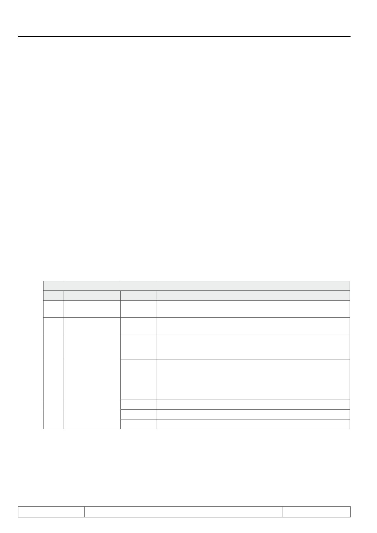
The target position is set in parameter PS.24 "Index position" in increments (scaling factor of the position set-
tings)
In parameter PS.27 "Index mode", the traversal manner (relative or absolute) is set.
PS.27: Index mode
Bit
Meaning
Value
Explanation
Continue of the
0
0: no
Must always be set to "0: no" for single positioning
profile processing
0: abso-
The position is given as an absolute value.
lute
The new position is set relative to the previous set point position.
2: relative
The direction (right or left of the old set point position) is determined
by the sign of the new position setpoint PS.24.
The new position is set relative to the previous target position. The
1..3
Position setting
6: relative
direction (right or left of the old target position) is determined via a
to PS.38
digital input (selectable via PS.38 and via the Input function "relative
(F R)
position F / R" in the parameters di.24...di.35, respectively). The sign
of the position setpoint is disregarded.
4
For special function "defined stop" (see chapter 7.12.4.11)
8, 10, 12
For special functions "rotary table" (see chapter 7.12.4.10)
14
reserved
Page7.12 - 34
Positioning and Synchronous Control
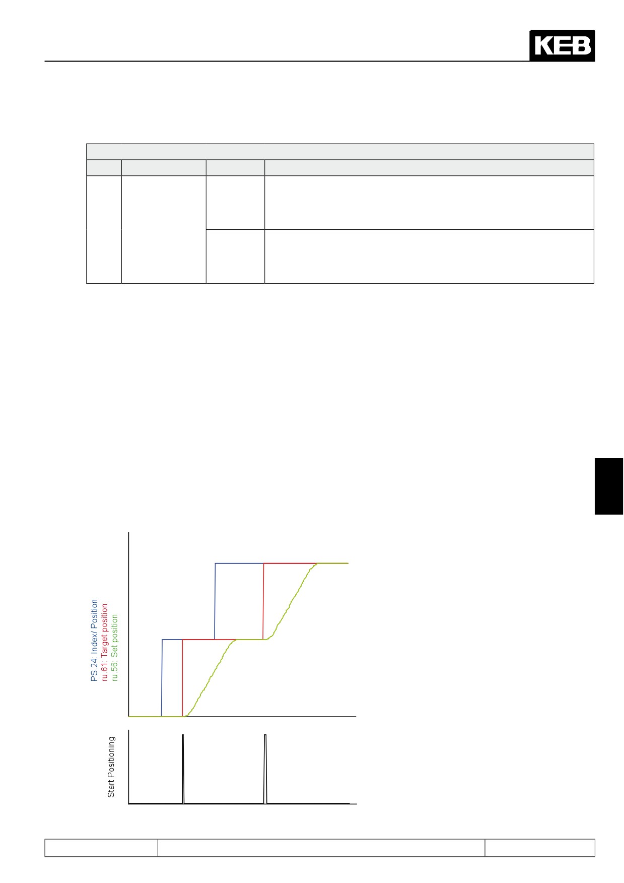
In parameter PS.00 is defined how the maximum profile speed is to be set:
PS.00: Posi-/Synchronous mode
Bit
Meaning
Value
Explanation
The maximum profile speed is set via PS.25 "Index speed". It is ac-
0:PS.25 /
quired at the time of the "start positioning" command and can not be
PS.25
changed thereafter for the positioning in progress. The drive stops at
Positioning /
the target position.
4
target speed
The maximum profile speed is calculated from:
16:PS.31 /
PS.31: "max. speed setting %" x oP.10: "max.reference forward"
PS.25
A change of the maximum profile speed during the current positioning
is possible.
Instructions for value 16:
If, during the current positioning, the value of PS.31 or oP.10 changes, the new profile speed is always acquired.
The drive runs (in compliance with the acceleration-, deceleration- and jolt-setpoints) to the new target speed.
The maximum profile speed can, therefore, be changed during a running positioning by writing to PS.31 via the
communication interface.
Alternatively, a change via an analog input is also possible:
For that purpose, enter in parameter An.53 "analog parameter setting source", e.g., the AUX-channel (value =
0), and program the bus address from parameter PS.31 (value = 131Fh) in parameter An.54 "analog parame-
ter setting destination". One can now adjust the maximum profile speed via the AUX-input (see also chapter
7.15.9).
The parameter PS.25 must be set to the value "0" , so that the drive stops at the target. If PS.25 contains a
value unequal to 0, the drive reaches this speed at the target position and continues running constantly at that
speed.
7
Example for a single positioning:
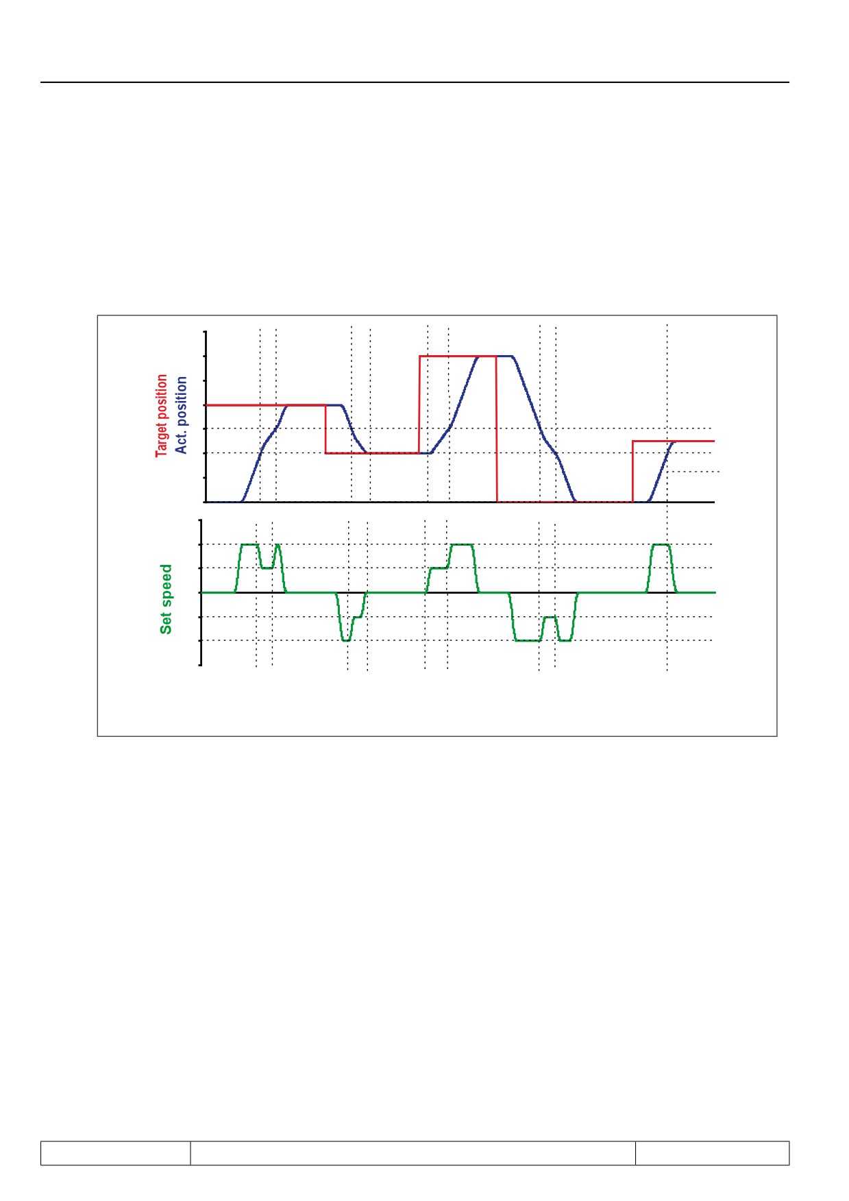
In PS.24, the position setpoint is specified. The
positioning mode is "absolute".
With the signal "start positioning" (function and
definition, see chapter 7.12.1.2), the position
setpoint is assumed as the new target positi-
on.
Corresponding to the predefined profile, the
set point position runs to the target position.
During (status ru.00 = 122: "positioning active")
or after the positioning (status ru.00 = 121: rea-
dy for positioning), a new position setpoint can
be defined which then becomes the new target
position with the next "start positioning" com-
mand.
Time
Page7.12 - 35
Positioning and Synchronous Control
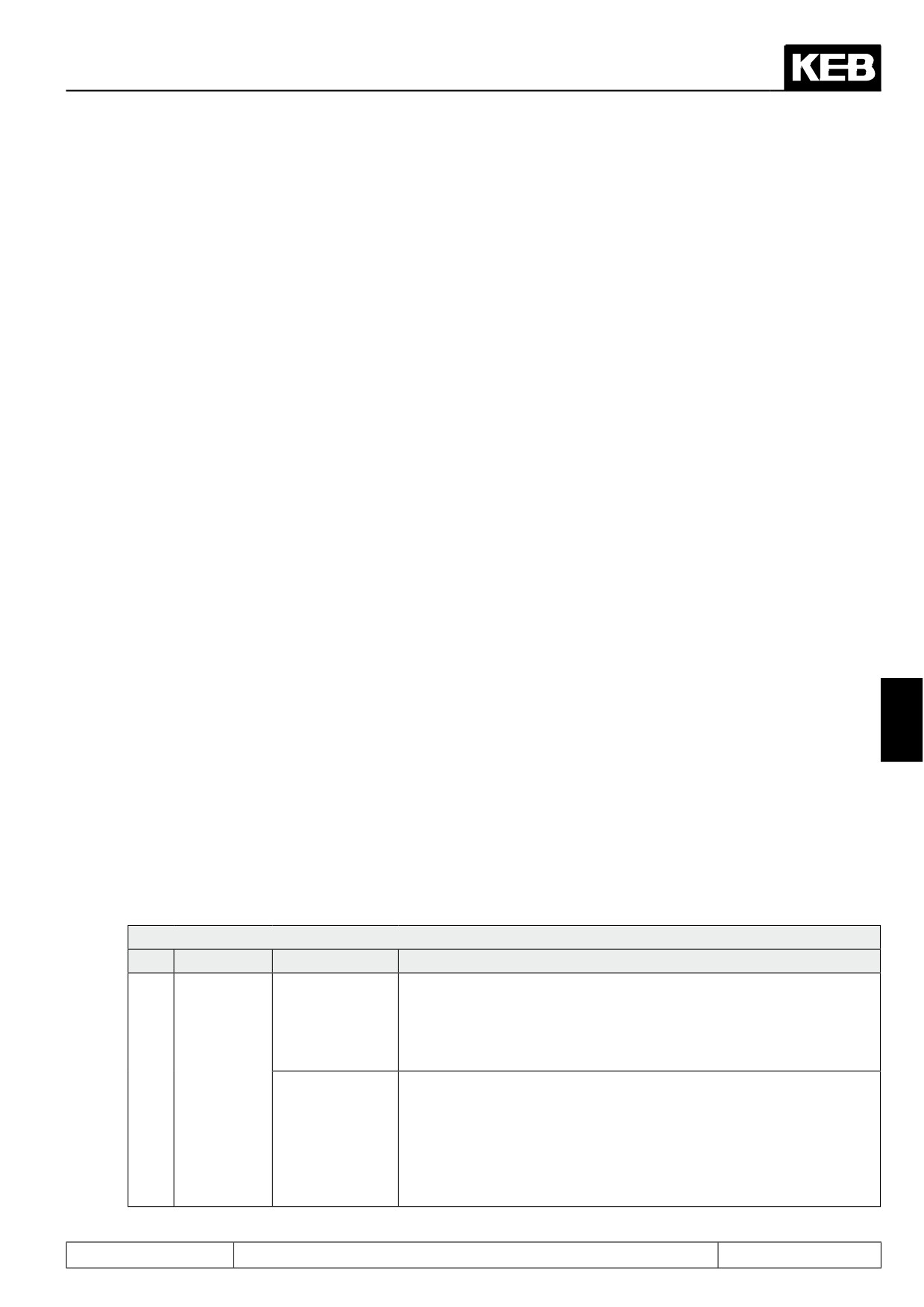
Example for a single positioning with variable maximum profile speed:
PS.00 bit 4 = 16
For an application, the drive shall always run with a lower profile speed between 2 positions
(e.g., joint in traversing rail). By switching the set , parameter oP.10 is decreased in this range.
After reaching this range, the drive decelerates according to the adjusted deceleration and jolt values to the
new maximum profile speed. This insures that during every positioning to an arbitrary position, the maximum
speed for this range is observed without the need for intervention by a superior control.
Time
Page7.12 - 36
Positioning and Synchronous Control
7.12.4.8
Posi mode / sequential positioning
With the sequential- or index-positioning, it is possible to run to several positions consecutively and, respec-
tively, traverse these with a defined speed.
If several target positions are defined in the inverter which are to be processed in that order, one calls it se-
quential positioning.
A possible example for a sequential positioning would be a drive that lowers a drill head. The drilling process
shall consist of 5 positioning steps:
● fast lowering of the drill with speed A from the starting position "0" up to position "1" ("1" = position just
before the material surface)
● slow penetration into the material (position "1" to "2") at speed B
● somewhat faster lowering (at speed C) during drilling of the material up to position "3"
● withdrawal of drill from the material at speed D, back to position "1"
● return to starting position "0" at speed A and stop there
This whole process can be realised using the sequential positioning.
To that end, so-called "blocks" are defined for every positioning step. Each block is marked by an index (i.e.,
numbered).
Each block contains the following information:
● PS.23: Index selection → number (index) of the block
● PS.24: Index position → target position for these block
● PS.25: Index speed → maximum profile speed and target speed (the exact function depends on the
7
programming of PS.00 bit 4 and is explained later)
● PS.26: Next index → contains the number of the block to be completed next
● PS.27: Index mode → defines the traversal manner (relative or absolute) and determines whether
the next positioning step (the next index) is started automatically
● PS.46: rel.correction switch forward / PS.47: rel.correction switch reverse → are only needed for
special applications. The default setting is 0: off. Description of the function in chapter 7.12.4.13
"flying referencing with correction")
Maximally 32 blocks can be programmed. There are two possibililties to define the maximum profile speed:
PS.00: Posi / synchronous mode
Bit
Meaning
Value
Explanation
Each block has its own maximum profile speed. The maximum profile
speed is set via PS.25 "Index speed". It is acquired at the time of the
0:PS.25/PS.25
"start positioning" command and can not be changed thereafter for
the positioning in progress. The speed at which to pass through the
target is determined by the PS.25 of the following block.
Positioning /
The maximum profile speed is defined for all blocks via PS.31 . A
4
target speed
change of the maximum profile speed during the current positioning
is possible. The maximum profile speed is calculated from:PS.31:
16:PS.31/PS.25
"max.speed setting %" x oP.10: "max.reference forward".
The speed at which to pass through the target is determined by the
PS.25 of the current positioning step. If the drive is to stop at the tar-
get, the target speed must be PS.25 = 0.
Page7.12 - 37
Positioning and Synchronous Control
There are 2 possibililties for the positioning process that are distinguished by PS.27 bit 0:
PS.27: Index mode
Bit
Meaning
Value
Explanation
Approach a position and wait for a new "start positioning" command.
Only after this occurs will the following block be completed (approach the
next position). This is necessary if the drive has to come to a standstill
at a position to, e.g., allow processing of a workpiece. The signal "target
0: no
window reached" is set. The signal to continue can come from an ex-
ternal control that supervises the processing. It can also be generated
automatically by a "timer" integrated into the inverter software. (Descrip-
tions of the timers in the context of the "start positioning" generation see
Continue of the
0
example 4 in this chapter).
profile processing
Automatic start of the next positioning step (defined in PS.26) without a
new "start positioning" command being necessary (as in the drill head
example). The drive does not stop at the target, but drives across it with
the speed chosen as positioning speed in the following block (PS.25 of
1: yes
the following block). (Exception: if in PS.00 the setting of the profile speed
by PS.31 is selected, then the target is crossed with the speed set in the
current block in PS.25). The switching condition "target window reached"
is not set since this is only an "intermediate target".
0: ab-
The position is given as an absolute value.
solute
The new position is set relative to the previous target position. The direc-
2: rela-
tion (right or left of the old target position) is determined by the sign of the
tive
new position setpoint PS.24.
The new position is set relative to the previous target position. The di-
6: rela-
rection (right or left of the old target position) is determined via a digital
tive to
1..3
Position setting
input (selectable via PS.38 and via the Input function "relative position F
PS.38
/ R" in the parameters di.24...di.35, respectively). The sign of the position
(F/R)
setpoint is disregarded.
4
For special functions "defined stop" (see chapter 7.12.4.11)
8,
10,
For special functions "rotary table" (see chapter 7.12.4.10)
12
14: re-
Do not adjust!
served
Page7.12 - 38
Positioning and Synchronous Control
In parameter PS.28 "start index new profile", the block with which the sequence begins is defined.
PS.28: Start index new profile
Value
Function
Number of the block with which the positioning sequence starts after the first "start positioning" com-
0...31
mand.
Start means the first positioning after:
● Activation of the positioning mode (e.g., by "power on" / setting of the input for activation of the posi-
tioning mode / activation of the positioning mode via PS.00 or the control word).
● Discontinuation of a running positioning (e.g., error message of the inverter / switching off of the con-
trol release or new "start positioning command" during a running positioning).
To clearly explain the sequential positioning, four examples are listed in the following:
● Sequential positioning with automatic continuation and definition of the profile speed by PS.25 (drill
head positioning).
● Sequential positioning with stop between the separate positioning steps. New start pulse by external
control required for each step. Definition of the profile speed by PS.25 (positioning of a workpiece for
various processing steps).
● Example 3 is a variation of example 2. The profile speed is defined by PS.31 instead of PS.25 . PS.31
is defined via an analog input.
● Sequential positioning with stop between the positioning steps. The length of pause is adjustable.
The new start pulse is generated automatically. Definition of the profile speed by PS.25. Utilisation of
the timer functionality and of the input / output handling of the inverter for generation of an automatic
sequence control (positioning of a workpiece for various processing steps)
7
If these detailed examples are not required, continue reading in chapter 7.12.4.10 positioning mode/ round
table.
Example 1: Realisation of the boring head positioning
Sequential positioning with automatically continuation and definition of the profile speed by PS.25.
Settings:
● Let the position at which the positioning process starts have the value 0.
● Driving to this position (whether after "power on", after error or as part of the positioning process) can
always occur at maximum speed = 1500 rpm.
● Let the position just before the material surface have the value 95,000. The speed at that point is to
be 250 rpm.
● The penetration is completed at position 100,000. Here, the drive may again have accelerated to 500
rpm. At that speed, drilling is continued up to position 150,000.
● The withdrawal from the material back to position 95,000 shall occur at 700 rpm.
● Thereafter, the drill head returns to the starting position at 1500 rpm.
● The drilling process is followed automatically.
Page7.12 - 39

Positioning and Synchronous Control
To solve this problem, several approaches are possible. An exact description of the available parameters and
alternative settings follows later in this chapter.
Adjustments:
PS.00: Posi /synchronous mode
Bit
Meaning
Value
Explanation
Posi / synchro-
0..2
5: Posi mode
Activation of the positioning mode
nous mode
The maximum profile speed is set via PS.25 "Index speed". The
Positioning /
0 : PS.25 /
4
speed at which to pass through the target is determined by the
target speed
PS.25
PS.25 of the following block.
All other bits can remain at the factory settings for this example and are explained in the following chapters.
●
Block 0 defines the start position
→ PS.28 = 0
●
block 0
→ PS.23: Index selection = 0
Position = 0
→ PS.24: Index position = 0
Permitted max. speed = 1500 rpm
→ PS.25 = 1500 rpm
next positioning step defined in block 1
→ PS.26 = 1
no automatic start of the drilling process, but wait for "start positioning" command, i.e., "continuation of
the profile processing" = 0:no and "position setpoint" = 0: absolute
→ PS.27 = 0: no + absolute
●
block 1
→ PS.23: Index selection = 1
Position = material surface
→ PS.24: Index position = 95000
Advance to material surface
→ PS.25 = 1500 rpm
next positioning step defined in block 2
→ PS.26 = 2
automatic continuation of the drilling process, i.e., "continuation of the profile processing" = 1:yes and
"Position setting" = 0:absolute
→ PS.27 = 1: yes + absolute
●
block 2
→ PS.23: Index selection = 2
Position = end of penetration
→ PS.24: Index position = 100.000
max. speed penetration
→ PS.25 = 250 rpm
next positioning step defined in block 3
→ PS.26 = 3
automatic continuation of the drilling process
→ PS.27 = 1: yes + absolute
●
block 3
→ PS.23: Index selection = 3
Position = end of drilling
→ PS.24: Index position = 150.000
max. speed drilling
→ PS.25 = 500 rpm
next positioning step defined in block 4
→ PS.26 = 4
automatic continuation of the drilling process
→ PS.27 = 1: yes + absolute
Page7.12 - 40
Positioning and Synchronous Control
●
block 4
→ PS.23: Index selection = 4
Position = material surface
→ PS.24: Index position = 95.000
max. speed retraction
→ PS.25 = 700 rpm
Retraction to starting position defined in block 0
→ PS.26 = 0
automatic retraction to starting position
→ PS.27 = 1: yes + absolute
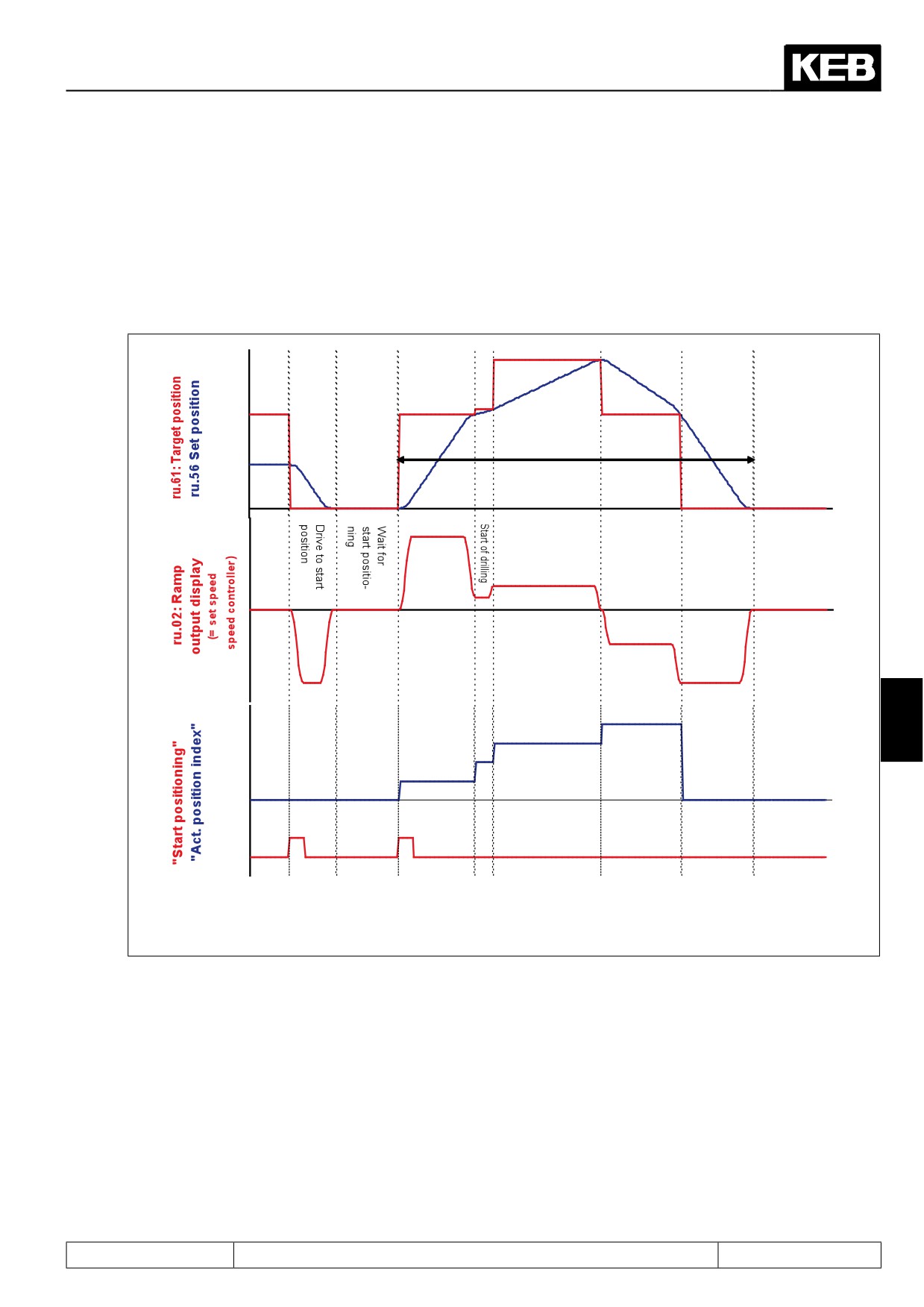
Automatically start of the drilling profile
Drive out of
Drive to
Drilling
start po-
the material
sition
Drive to
start of
material
7
Time
In the example above, the drive did not stop after each step in the drilling process, instead, the target position
of the individual steps was crossed already at the speed set for the next drilling step. I.e., the parameter PS.25
"index speed" defines the positioning speed for a block, while the value of PS.25 of the following block deter-
mined the speed at which the target position is crossed.
For example: the "penetration block" is block 2. The speed during of the penetration (the positioning speed) is
the value of PS.25 in block 2 = 250 rpm.
The drilling is to continue at 500 rpm, so the drive already accelerates at the end of the penetration to the drilling
speed of 500 rpm, i.e., the value of PS.25 in block 3. The speed at which the target of block 2 is passed (= the
target speed) is also determined by block 3 (the following block).
If the drive has to reverse to reach the next target (change the direction of rotation) or if the next target shall
not be driven to automatically (PS.27: "continuation of the profile processing" = no), the target speed of a block
automatically becomes 0 (standstill at target).
Page7.12 - 41
Positioning and Synchronous Control
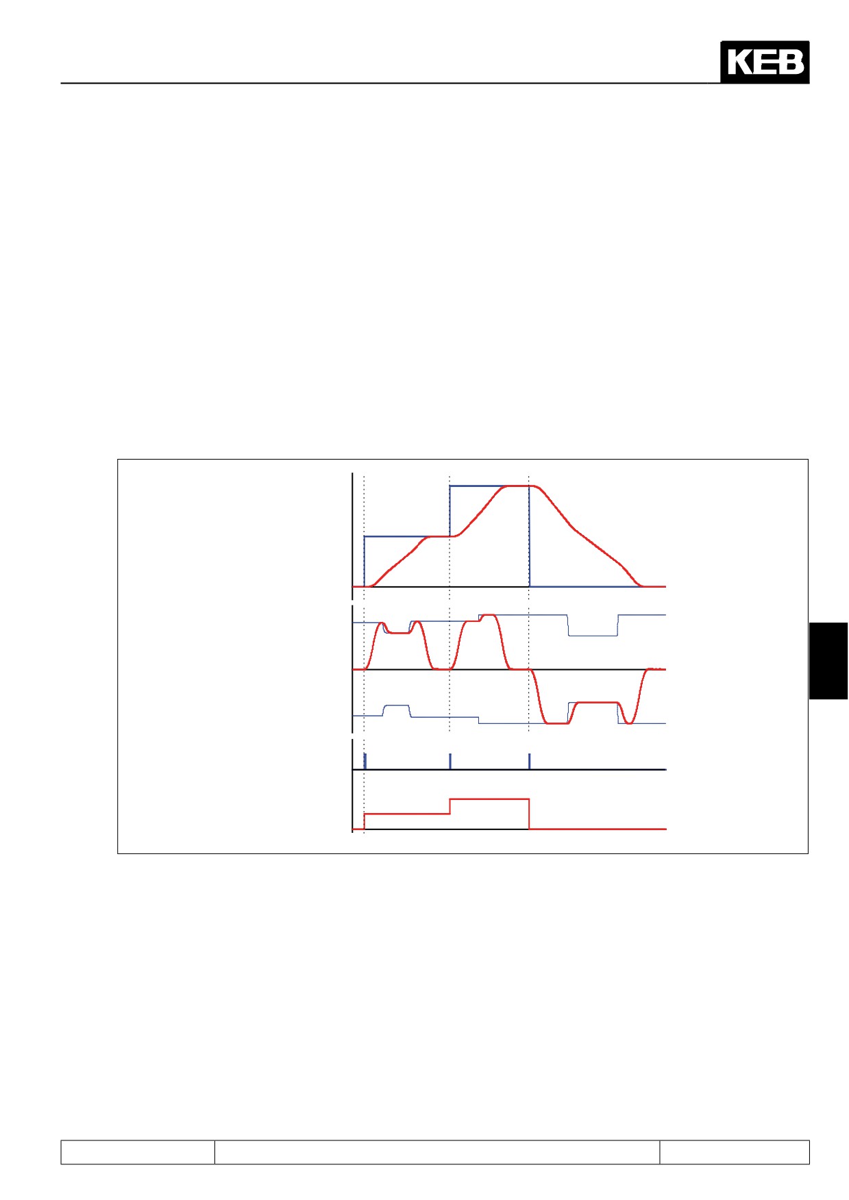
Example 2: Positioning of a workpiece for various processing steps/ sequence control by external control
Sequential positioning with stop between the positioning steps and definition of the profile speed by PS.25.
Settings:
● The drive shall stop at each position to allow processing of the workpiece, until the external control
gives the signal to continue, i.e., "start positioning". The external signal comes from input I3. The drive
shall signal the control via an output that it has reached the current target with an accuracy of 10 in-
crements, so that the processing can begin.
● Let the position at which the workpiece starts have the value 0.
● Driving to this position (whether after "power on", after error or as part of the positioning process) can
always occur at maximum speed = 1500 rpm.
● The first stop shall be at position 100,000. The profile speed up to that point shall be 1000 rpm.
● The second stop shall be at position 200,000. The profile speed up to that position shall again be 1000
rpm.
● After that, the drive shall retract to its starting position at maximally 1500 rpm.
Adjustments:
●
PS.00:
PS.00: Posi / synchronous mode
Bit
Meaning
Value
Explanation
Posi / synchro-
0...2
5: Posi mode
Activation of the positioning mode
nous mode
Positioning /
0 : PS.25 /
4
The maximum profile speed is set via PS.25 "Index speed".
target speed
PS.25
All other bits can remain at the factory settings for this example and are explained in the following chapters.
● Block 0 defines the start position
→ PS.28 = 0
● Input I3 serves as "start positioning"
→ PS.29 = 64: I3 (X2A.12)
● block 0
→ PS.23: Index selection = 0
position = 0
→ PS.24: Index position = 0
Permitted max. speed = 1500 rpm
→ PS.25 = 1500 rpm
next positioning step defined in block 1
→ PS.26 = 1
no automatic start, but wait for "start positioning" command, i.e., "continuation of the profile proces-
sing" = 0:no and "position setpoint" = 0: absolute
→ PS.27 = 0: no + absolute
Page7.12 - 42
Positioning and Synchronous Control
● block 1
→ PS.23: Index selection = 1
Position = first stopping point
→ PS.24: Index position = 100.000
speed up to the first stopping point
→ PS.25 = 1000 rpm
next positioning step defined in block 2
→ PS.26 = 2
Stop at the position, i.e., "continuation of the profile proces-
→ PS.27 = 0: no + absolute
sing" = 0:no / "position setpoint" = 0:absolute
● block 2
→ PS.23: Index selection = 2
Position = second stopping point
→ PS.24: Index position = 200000
speed up to the second stopping point
→ PS.25 = 1000 rpm
next positioning step back to start
→ PS.26 = 0
stop at the position
→ PS.27 = 0: no + absolute
ru.61: Target
position
ru.54:Act.
position
ru.02: Ramp
output display
7
ru.63/ -ru.63
Profile speed
I3 (X2A.12) Start
positioning
ru.60: Act.
position index
Time
Page7.12 - 43