KEB COMBIVERT F5-A,-E,-H 4.0. APPLICATION MANUAL (2008) - page 20
Protective Functions
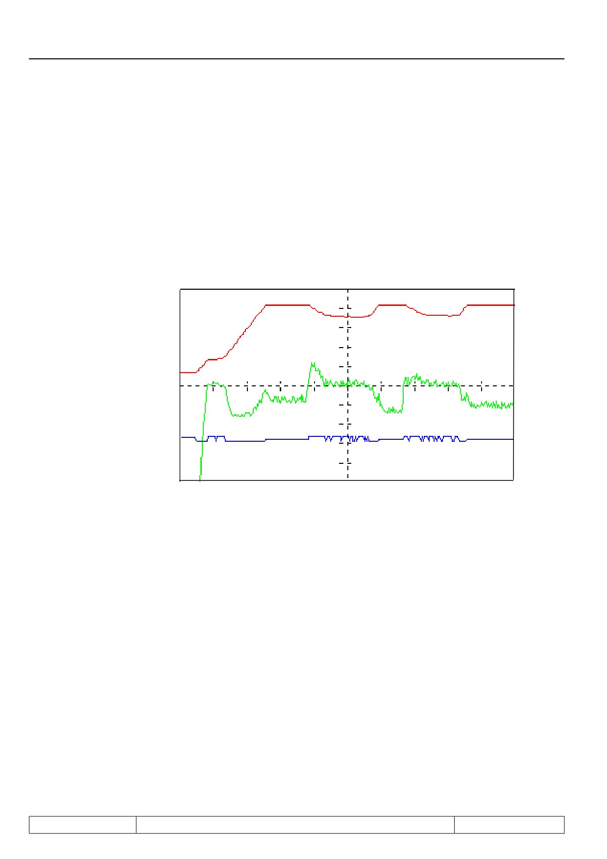
Stall level (Pn.20)
The max. constant current represents the setpoint for the control. The adjusted value refers to the inverter rated
current (In.01).
Setting range:
0...199 %; 200 = off (default)
Stall acc/dec time (Pn.21)
Depending on the setting of Pn.19 (bit 3) the ramp time or the time constant of the differential controller is ad-
justed here. The ramp time refers to 100 Hz / 1000 rpm (depending on ud.02).
Setting range
0...300,00 s (2,00 s default)
Fig. 7.13.2
Functioning of Stall-function with standard setting
adjusted
constant current limit
Actual frequency (ru.3)
Inverter status (ru.0)
Act. utilisation (ru.13)
Page7.13 - 24
Protective Functions
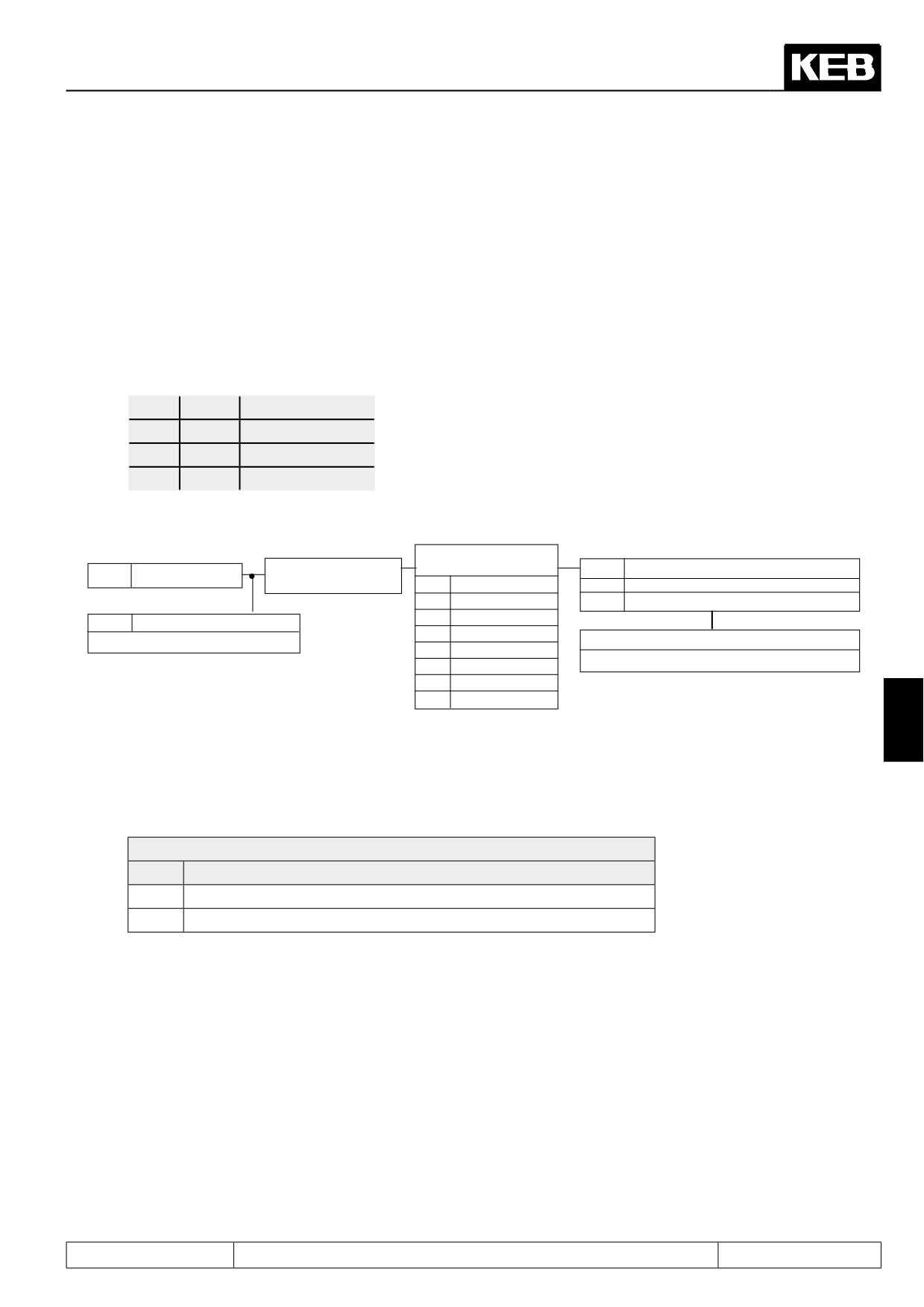
7.13.9Motor Protection Mode
Functional description for F5A-M and F5H-M
The motor protective function protects the connected motor against thermal destruction caused by high cur-
rents. The function corresponds largely to mechanical motor protective components, additionally the influence
of the motor speed on the cooling of the motor is taken into consideration. The load of the motor is calculated
from the measured apparent current (ru.15) and the motor prot. rated current (dr.12).
For motors with separately driven fan or at rated frequency of a self-ventilated motor following tripping times
(VDE 0660, Part 104) apply:
1,2
• In
→ 2 hours
1,5
• In
→ 2 minutes
2
• In
→ 1 minute
8
• In
→ 5 seconds
Fig. 7.13.8.a Motor protection mode
Fr.8
Motor set
Parameter set selection
classification
dr.11
Electronic motor protection
ru.15
Apparent current
see Chapt. 6.8
0
Counter
0
0
Separate cooling
1
Counter
1
1
Self-cooling
2
Counter
2
dr.12
Motor protect. rated current
3
Counter
3
0.1…460.0 A
Pn.14
Motor protect. function response
4
Counter
4
0...6 (see Chapt. 6.7.6)
5
Counter
5
6
Counter
6
7
Counter
7
7
Motor protection mode (dr.11)
With this parameter, the cooling mode of the motor is set.
dr.11: Motor protection mode
Value
Function
0
Separate cooling (default)
1
Self-cooling
Motor protection rated current (dr.12)
This parameter specifies for each set the rated current (= 100% utilisation) for the motor protective function.
The motor protection-load is calculated as follows:
Inverter Apparent current
(ru.15)
Motor protection-load =
——————————————
Motor protection rated current
(dr.12)
Page7.13 - 25
Protective Functions
Warning OH2 stopping mode (Pn.14)
Pn.14 specifies the performance of the drive on activation of the motor protective function.
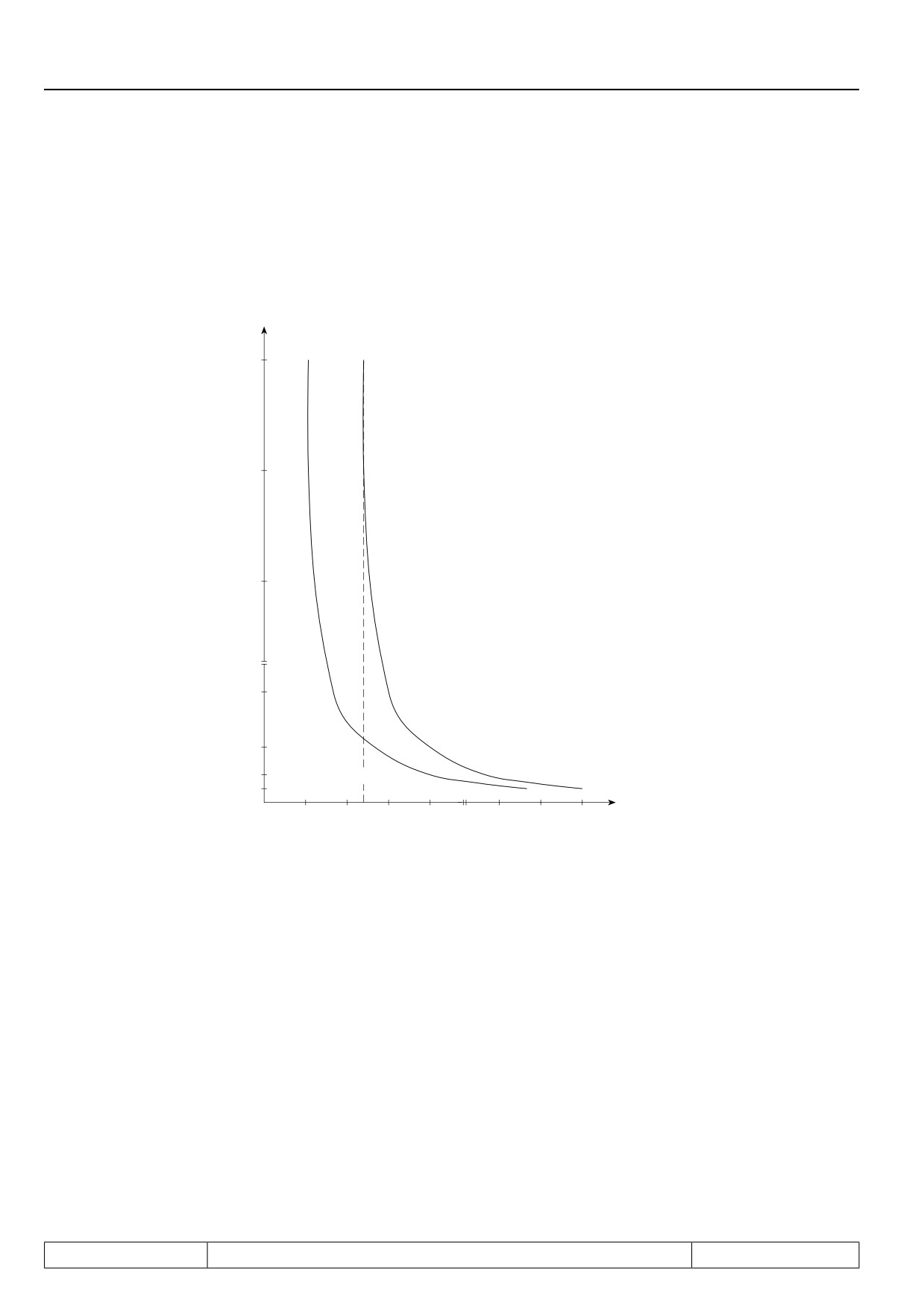
Fig. 7.13.8.b Tripping times for F5-B, F5-G and F5-M
Tripping
f
≥ Rated motor frequency
time
or
forced-ventilated motor
120 min
f = 0 Hz
60 min
30 min
Motor current
2 min
1 min
30 sec
120
5 sec
%
50
100
150
200
400
600
800
For self-ventilated motors the tripping times decrease with the frequency of the motor (see picture). The motor
protective function acts integrating, i.e. times with overload on the motor are added, times with underload are
subtracted. After triggering the motor protective function, the new tripping time is reduced to 1/4 of the specified
value, if the motor has not been operated for an appropriate time with underload.
Motor protection function for F5-M
In some applications, several motors are operated alternatively on one inverter. The changeover between the
motors takes place synchronously with the set changeover.
The motor protection function must then be able to distinguish which of the motors is currently being supplied.
For that purpose there is the parameter Fr.08 "motor set classification". Each motor is assigned a number from
0 to maximally 7, and this value is transferred to the parameter Fr.08 in all sets where the respective motor is
supplied.
Page7.13 - 26
Protective Functions
Example:
3 motors are operated alternately on the inverter.
assigned number
engaged if the active parameter set (ru.26) is equal to:
Motor 1
0
0, 1, 2, 3
Motor 2
1
4, 5
Motor 3
2
6, 7
The following programming must then be done:
Set 0
Fr.08 = 0
Set 4
Fr.08 = 1
Set 6
Fr.08 = 2
Set 1
Fr.08 = 0
Set 5
Fr.08 = 1
Set 7
Fr.08 = 2
Set 2
Fr.08 = 0
Set 3
Fr.08 = 0
The motor protection function is calculated separately for all motors, i.e., for each individual motor, a separate
overload counter is running.
If one of the counters reaches the limit of 100%, the behaviour programmed in Pn.14 "Warning OH2 stopping
mode" is triggered.
Motor protection function for F5-S
The motor protection function is activated if the ratio apparent current (ru.15) to continuous current (Is/Id)
exceeds the value of dr.50 "Motor protection min Is/Id". The release time for this point is set in dr.34 "Motor
protection time min Is/Id". In dr.35 "motor protection time Imax", the release time for maximum current is set. If
a greater value is programmed in dr.35 than in dr.34, the time dr.34 is valid in the whole range.
7
The maximum current is defined by dr.33 "DSM max. torque" or dr.15 "max. torque FI". The smaller of the two
values determines the maximum current.
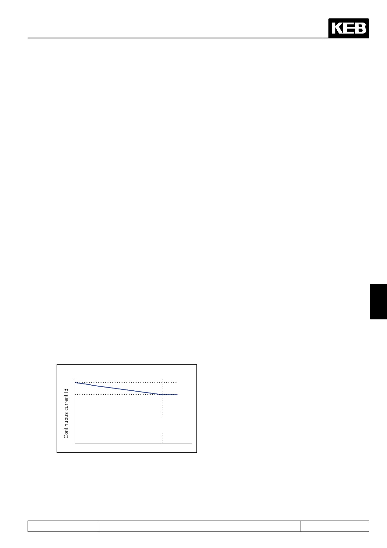
The continuous current is speed-dependent. At speed 0, it is equal to dr.28 "DSM current for zero speed" and
at dr.24 "DSM rated speed", it reaches the value dr.23 "DSM rated current".
dr.28
DSM curr. f. zero speed
dr.23
DSM rated current
dr.24
DSM rated speed
Speed
The tripping time is the time, which the internal counter needs, in order to count from 0 to 100%. On reaching
100%, the error "30: ERROR! Motor protection function" (E.dOH) is triggered.
Page7.13 - 27

Protective Functions
Release time
dr.34
Motor prot. time
min Is / Id
dr.35
Motor prot. time
Motor current / Continuous
Imax
current
dr.50
dr.33
Is / Id
Motor prot.
Cont.current
min Is / Id
A warning level can be adjusted in Pn.15 "OH2 warning level". If the counter reaches this level, the adjusted
response in Pn.14 "Warning OH2 stop. mode" is executed.
The counter is reduced if the relation apparent current to continuous current is < dr.50. The recovery time dr.36
"motor protection recovery time" is the time the counter requires to count from 100% to 0% (after triggering of
the error, i.e., when no current is flowing). The error triggered by the motor protection function can already be
reset before the recovery time expires.
Page7.13 - 28
Protective Functions
7.13.10
Power-Off function
It is the task of the Power-Off function to ensure a controlled deceleration of the drive until standstill in case of
undervoltage (e.g. due to power failure). The kinetic energy of the rotating drive is used to support the inverter
DC-link voltage. As a result the inverter remains in operation and can decelerate the drive in a controlled man-
ner.
Especially in the case of parallel running drives (e.g.textile machines) the uncontrolled running down of the
motors and the consequences resulting from it (thread breakage) can be avoided.
For the various operating modes, the amount of available functions differs.
For the vector controlled modes, some parameters have no function or are even hidden.
Here is an overview:
Parameter
V/F-characteristic
Vector-controlled
Vector-controlled
operation
DASM
DSM
Pn.44 Power off mode
yes
yes
yes
bit 0, 1, 3..4
yes
yes
yes
bit 2, 8
yes
No function
No function
bit 6..7
yes
only values 0 and
No function
192
Pn.45 Power off start voltage
yes
yes
yes
Pn.46 Power off auto st. level
yes
yes
yes
Pn.47 Power off brake torque
yes
No function
hidden
Pn.48 Power off restart level
yes
yes
hidden
Pn.50 Power off ref. DC voltage
yes
No function
hidden
Pn.51 Power off KP DC voltage
yes
yes
hidden
7
Pn.52 Power off restart delay
yes
yes
yes
Pn.53 Power off KP act. current
yes
No function
hidden
Pn.54 Power off KI act. current
yes
No function
hidden
Pn.55 Power off KD act. current
yes
No function
hidden
Pn.56 Power off jump factor
yes
No function
hidden
Pn.57 Power off KI DC voltage
yes
yes
hidden
Page7.13 - 29
Protective Functions
Power-Off Mode (Pn.44)
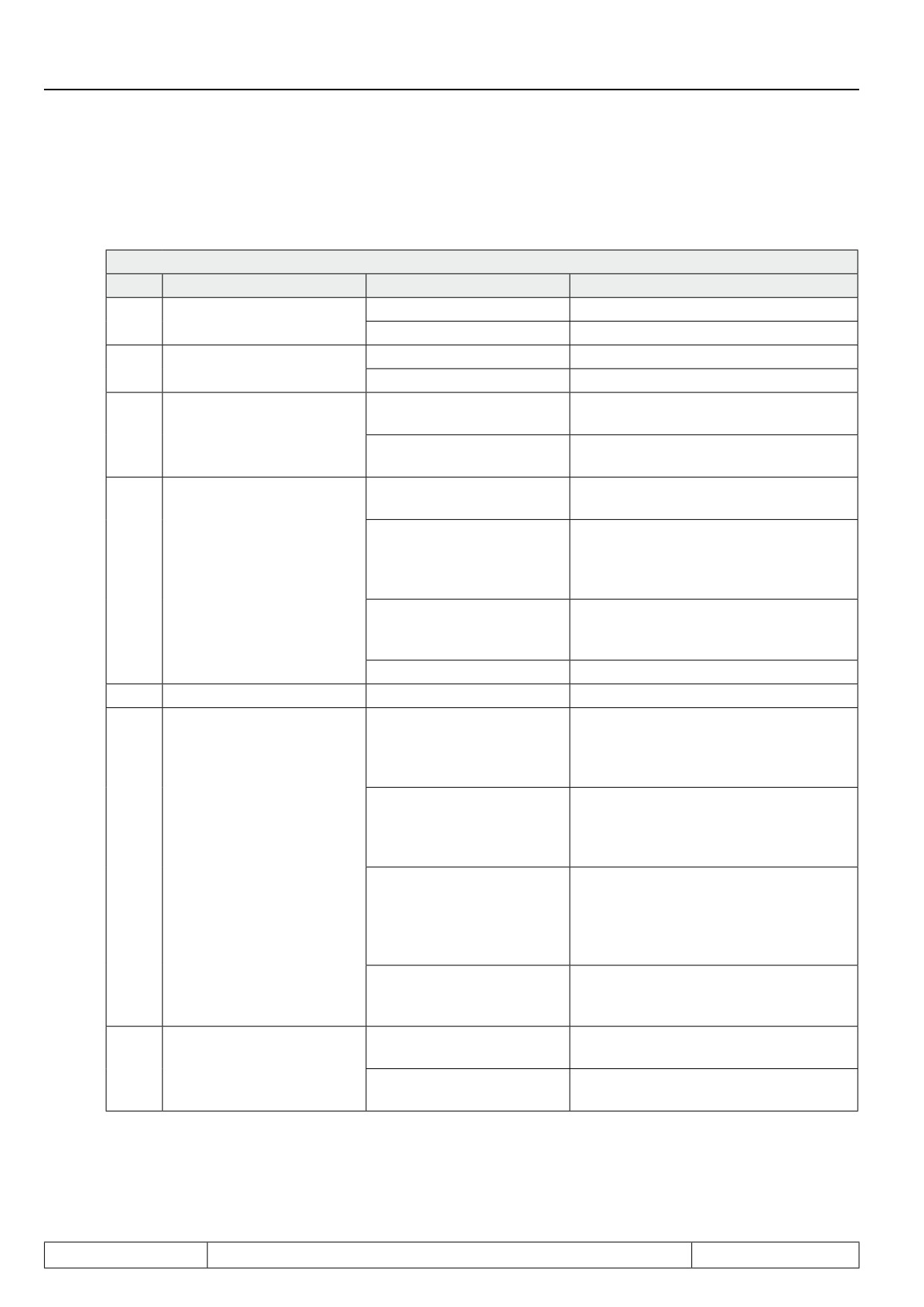
The parameter Power-Off-Mode (Pn.44) switches on the function and determines the basic behaviour:
Pn.44: Power off mode
Bit
Meaning
Value
Explanation
0: off
Power-off function deactivated
0
Power off / activation
1: on
Power-off function activated
0: automatically
Auto determination of the start voltage
1
Release voltages
2: fixed level (Pn.46)
Preset the start voltage with Pn.46
Determination of the initial jump from the
0: from the slip
calculated slip
2
Initial jump (only v/f-.)
Determination of the initial jump from the
4: from the load
load factor
Status "78: power-off function active"
0: Mod. on, no restart
(POFF), modulation on, reset required
Status "78: Power-off function active"
(POFF), modulation on, restart on power
8: Mod. on, restart
Behaviour on reaching
recovery after Pn.52 "Power off restart
3..4
standstill
delay"
Status "84: no direction of rotation after
16: PLS, no restart
power off" (PLS), modulation off, reset
required
24: reserved
reserved
5
reserved
0 / 32: reserved
reserved
Bridging of mains gaps
Restart on power recovery, as long as
0: Starting voltage
the initial speed is not lower than Pn.48
"Power off restart value".
Emergency stop without braking modu-
64: Voltage setpoint Pn.50
le
(only v/f-char.)
Restart possible only on reaching stand-
Voltage setpoint selection
still.
6..7
(not for vector contr. DSM)
Bridging of mains gaps
128: Voltage setpoint
Restart on power recovery above Pn.48
Pn.50, if init.speed < Pn.48
"power off restart level".
(only v/f-char.)
Setpoint increase from initial voltage to
voltage setpoint below Pn.48.
Emergency stop with braking module
192: Braking torque (Pn.47)
Restart possible only on reaching stand-
still.
Voltage stabilization during power off =
0: on
Voltage stabilisation on
uF.09
8
power off (only v/f-char.)
Voltage stabilization during power off de-
256: off
activated
Tripping of Power-Off
The Power-Off function starts when the DC-link voltage drops below a certain value, the start voltage. The start
voltage can be set automatically or manually depending on Pn.44 Bit 1.
Page7.13 - 30
Protective Functions
Power off start voltage (Pn.45)
With manual adjustment the starting voltage can be preset with Pn.45 in the range of 200...1200 volt. For a
secure range the adjusted starting voltage must be at least 50V over the UP-threshold (UP: 200V class = 216V
DC; 400V class = 240V DC; 600V class = 360V DC)
Power off auto start level (Pn.46)
With Pn.46, the auto starting voltage is set in the range of 50...90% (Default: 80 %) of the rated DC link voltage
(ru.68).
The rated DC link voltage is measured on "Power on" and is displayed in ru.68.
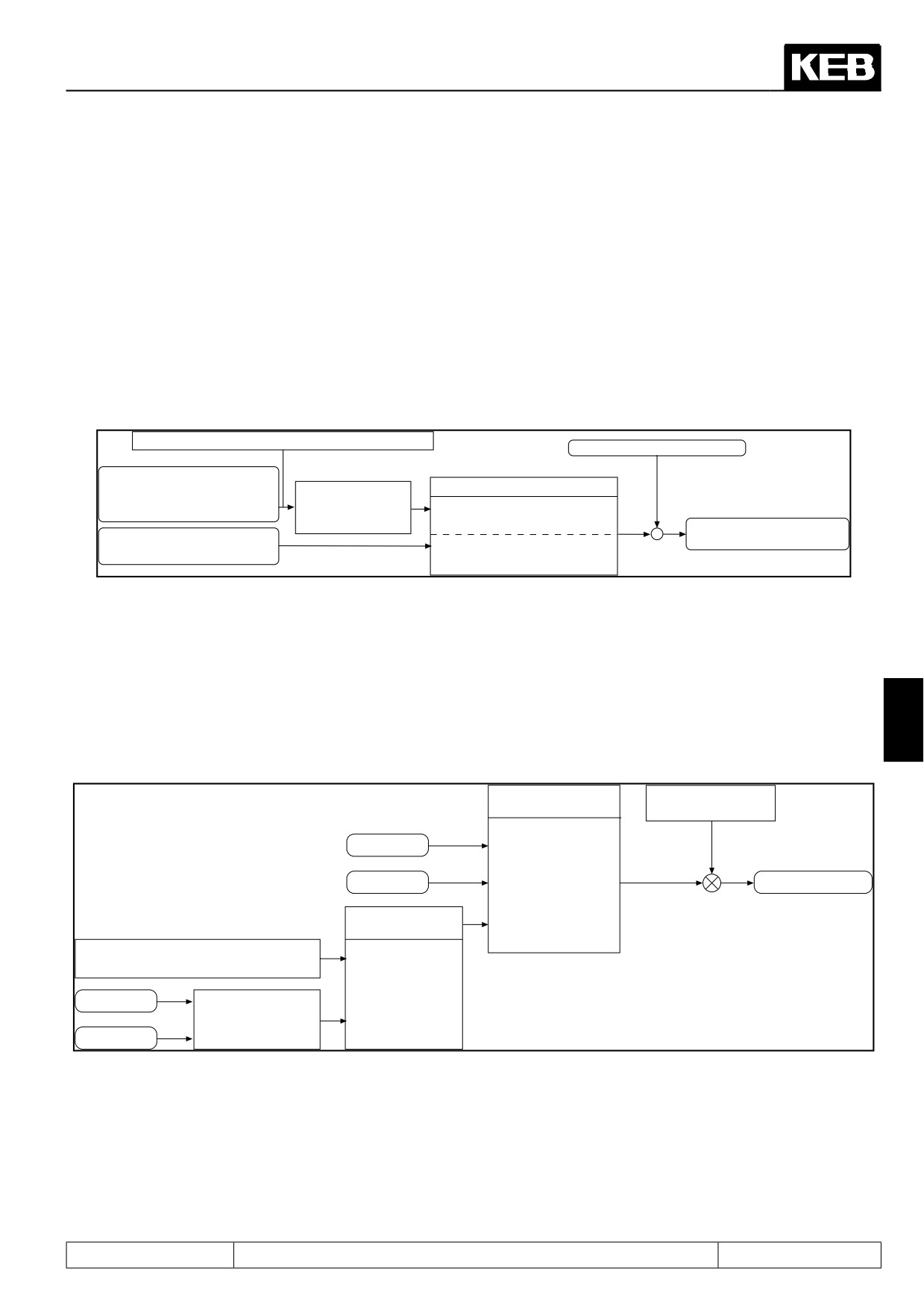
Picture 7.13.10.a Starting the Power-Off function
ru.68 Rated DC voltage
DC-link voltage real value
Auto-DC-link voltage set value
Pn.44 Bit 1 starting voltage
measured at Power-On
Pn.46 Auto starting
voltage
0: auto determination of the start
voltage
50...90% (80%)
-
Start of power off if UZK-
Pn.45 starting voltage
+
actual value < start. volt.
2: preset the start voltage with
200...1200 V
Pn.45
Initial jump for generator operation (only v/f-characteristic operation)
First of all the drive must be brought into generatoric operation to enable the feed back
of energy into the intermediate circuit. This is achieved by making a frequency jump, so
that the speed of the drive is larger than the output rotating field speed of the inverter
7
Figure 7.13.10.b Initial jump for generator operation in 1. cycle
cS.01 act. source
Pn.56 Jump factor
0...800 %
Channel 1
0: Encoder channel 1
Channel 2
1: Encoder channel 2
Frequency jump
Pn.44 bit 2
Starting jump
2: calculated actual
value
Slip calculation by the active
current
0: Active current IW
Motor data
Slip calculation
4: Utilisation IS
Utilisation
Initial jump calculation (Pn.44 Bit 2)
The parameter Pn.44 bit 2 determines, whether the starting jump is calculated from the active current or from
the utilisation. This setting has no effect on slip regulation. Default value is the calculation of the active current,
but in the case of high harmonic content of the output current it can lead to false values. In that case the starting
jump must be determined from the utilisation. To get proper values enter motor data into dr-parameters first.
Page7.13 - 31
Protective Functions
Power off jump factor (Pn.56)
By means of the jump factor the automatically determined starting jump can be adapted to the respective ap-
plication.
In case the jump factor is too small, the inverter trips to "2 ERROR! Undervoltage" (E.UP)!
For too great a jump factor, the inverter runs into the hardware current limitation (status value 80 "HCL"). The
control cannot work correctly, thus causing a wrong calculation of the active current!
Power off controller (not for vector controlled operation with DSM)
There are two controllers: the DC-link voltage controller and the active current controller.
The active current controller is downstream of the DC link voltage controller in v/f-characteristic operation.
In vector controlled operation, the output of the DC link voltage controller is used as the torque limit.
If the braking torque is selected as the setpoint (Pn.44 bit 6...7 = 3), the DC link voltage controller is deactiva-
ted.
setpoint = start voltage (Pn.44 Bit 6...7 = 0)
The initial voltage value selected with Pn.44 bit 1 is the setpoint of the DC link voltage controller (see also:
tripping of Power-Off
This setting serves to bridge voltage drops. On power recovery, the drive restarts if the initial speed has not yet
fallen below the "power off restart value" (Pn.48).
Setpoint = braking torque (Pn.47; Pn.44 bit 6...7 = 3) (only V/F characteristic operation)
The braking torque can be preset within the range of 0,0...100,0 %.
The braking torque is used as setpoint value source, if the drive must be stopped as quickly as possible in case
of power failure. The DC link voltage controller is switched off in this case. Since the DC link voltage increases
very strongly in this mode, a braking module is required.
Since the hardware current limit should not be reached with active current control, the setpoint value is limited
internally which can lead to oscillations. In that case the setpoint value can be reduced, which leads to prolon-
gation of the delay. If the voltage stabilization is switched on (Pn.44 bit 8 = "1") and uf.09 = rated voltage is
adjusted, the voltage is not so high and the deceleration becomes more uniform.
Setpoint = voltage setpoint (Pn.50; Pn.44 bit 6...7 = 1 or 2) (only V/F characteristic operation)
The setpoint DC-link voltage can be preset in the range of 200...1200 V. To ensure a safe operation the internal
value is limited down. The value of the DC-link voltage in normal operation plus approx. 50V adjusts itself as
minimum value. If a braking resistor is connected, the adjusted value may not lie above the threshold of the
braking resistor, else the controller cannot work (threshold 200V-class: 380V; 400V-class: 740V; 600V-class:
1140V).
If Pn.44 Bit 6...7 = 1, the voltage setpoint is used as setpoint immediately after the triggering of power off. In this
mode, a restart is possible only after reaching standstill.
In mode Pn.44 Bit 6...7 = 2, initial voltage is adjusted to first after triggering. On undershooting the restart value
(Pn.48), the setpoint is increased to the voltage setpoint (Pn.50) with a ramp. This achieves that the drive still
has enough energy for braking when reaching standstill in critical applications.
Page7.13 - 32
Protective Functions
KP DC link voltage controller (Pn.51), KI DC link voltage controller (Pn.57)
To be able to adapt the drive individually to the application, the proportionality factor of the DC link-voltage con-
troller can be adjusted with Pn.51 and the integer factor with Pn.57 (not for F5-B/C), in the range of 0...32767.
In most cases the default setting will achieve sufficient results. If, however, overshoots or fall backs of the motor
occur, the values must be lowered.
KP (Pn.53), KI (Pn.54), KD (Pn.55) (only V/F characteristic operation)
Pn.53, Pn.54 and Pn.55 are the controller parameters of the active current controller
A D-part usually has a positive effect on control. Pn.55 should have approx. 10-times the value of Pn.53.
Behaviour on power recovery and below the restart value (Pn.48)
The following parameters effect the behaviour of the inverter if the system voltage returns during the Power-
Off-function.
Restart value (Pn.48)
Depending on the individual case, it can be reasonable to execute the restart on power recovery only above a
defined base value. This restart value is adjusted in Pn.48.
Dependent on the setpoint value source (Pn.44 bit 6 ..7) following conditions occur:
1. Control to the starting voltage (Pn.44 Bit 6...7 = 0):
If the output value is larger than the restart value, the restart is carried out upon power recovery. The output
value is kept constant during the restart delay
(Pn.52). Afterwards it is accelerated to the current setpoint va-
lue. Below the restart value it is delayed in case of power recovery with the fast-stop-function ( DEC-ramp at
F5-B/C). If the power does not recover, the controller parameters of the active current controller are decreased
linearly with the base value in v/f-characteristic operation.
7
2. Control to voltage setpoint Pn.50 for a base value smaller than the restart value (Pn.44 bit 6...7 = 2):
As long as the base value is greater than the restart value, the inverter behaves as in item 1. Below the restart
value the voltage setpoint value of Pn.50 is increased and with active current control (without speed detection)
the control parameters of the active current control are reduced linearly with the output value. On power reco-
very, a restart is then only possible after reaching standstill.
3. Control to voltage setpoint Pn.50 or braking torque Pn.47 (Pn.44 bit 6.,.7 = 1 or 3):
The control parameters of the active current control (without speed detection) are reduced below the restart
value linearly with the output value.
On power recovery, a restart is possible only after reaching standstill.
Behaviour on reaching standstill (Pn.44 Bit 3.,.4)
Pn.44 bit 3..4 determines how the drive behaves on reaching standstill.
Pn.44 bit 3...4 = 0:
The inverter modulates independent of a set direction or rotation with the adjusted boost and is in status "78:
power off function active" (POFF). Attention: Motor warming! A reset is necessary for the restart.
Pn.44 bit 3...4 = 1:
The inverter modulates independent of a set direction or rotation with the adjusted boost and is in status "78:po-
wer off function active" (POFF). After expiration of the restart delay Pn.52 (if adjusted) the inverter restarts
automatically.
Pn.44 bit 3...4 = 2:
The inverter switches off the modulation and is in status "84: no direction of rotation after power off" (PLS). A
reset is necessary for the restart.
Page7.13 - 33
Protective Functions
Restart delay (Pn.52)
If a restart is allowed the restart delay time is kept constant after power recovery of the output value. It is ad-
justable within the range of 0...100 s (Default 0 s). After expiration of this time it is accelerated again onto the
current setpoint.
Examples of the power off-operating modes
To better illustrate the context, the operating modes are explained in more detail in the following section.
Bridging of mains gaps (not for vector controlled operation with DSM)
Setpoint source:
Starting voltage (Pn.44 bit 6..7 = 0)
Voltage setpoint Pn.50, if base value < Pn.48 (Pn.44 Bit 6..7 = 2)
In this mode the motor shall be operated almost in no-load operation and only recover the energy which the
inverter requires for the operation. The starting voltage is at the same time the setpoint value for the DC-link
voltage control. In V/F characteristic operation, the set value is the setpoint of the active current controller, and
in vector controlled operation, the torque limit of the speed controller.
In case of weak supply systems it is recommended to choose the automatic starting voltage, as in this case the
starting voltage value is adapted to slow voltage fluctuations.
In the first cycle, a speed jump is issued in V/F characteristic operation, and in vector controlled operation, the
limit of the speed controller is set to the measured slip so that the drive is put in no-load operation.
To safely decelerate the drive in v/f-characteristic operation, the controller parameters of the active current
controller are lowered to below of the restart value, linearly with the base value.
Restart at power recovery
Only in this mode the system recovery can be constantly detected. An immediate restart upon power recovery
is possible.
After detecting the power recovery the restart delay (Pn.52) runs down and the drive accelerates to the current
setpoint value.
An immediate restart is not executed below the restart value (Pn.48). The drive decelerates with the quick stop
function (Pn.60..61) and behaves according to the adjustment in Pn.44 bit 3...4.
To have more energy available for braking the inertial mass on reaching standstill in v/f-characteristic operation,
the voltage setpoint for undershooting the restart value (Pn.48) can be increased to the voltage setpoint (Pn.50)
(Pn.44 Bit 6...7 = 2).
In this case the control remains active with the increased setpoint value. A restart is then possible only after
reaching standstill. Thereafter, the behaviour is define by Pn.44 Bit 3...4.
In this mode, too, the lowering of the controller parameter is executed.
Emergency stop with braking module (not for vector controlled with DSM)
Setpoint source:
Brake torque (Pn.44 bit 6...7 = 3)
In this mode the drive is to be stopped as fast as possible. Since the recovered energy can be very high, a
braking resistor is necessary.
The DC-link voltage controller is not active. In v/f-characteristic operation, the setpoint of the active current
controller is the braking torque (Pn.47). In vector controlled operation, the drive decelerates with the abnor-
mal stopping-function (Pn.60, 61, 67; see chapter 7.13.5) and behaves dependent on the setting in Pn.44 Bit
3...4.
In v/f-characteristic operation, the drive supplies no energy anymore at low speed. In this case, the control must
be very soft, to prevent fall back.
It is possible to adjust the restart (Pn.48). The controller parameters of the active current controller are lowered
to below this value, linearly with the base value.
Page7.13 - 34
Protective Functions
Emergency stop without braking module (only V/F characteristic operation)
Setpoint source:
voltage setpoint Pn.50 (Pn.44 Bit 6...7 = 1)
In some cases one can do without a braking module with the Emergency-stop function, if the losses in the motor
are very high at high DC-link voltage.
The voltage stabilization should be switched off in this case. This can be done with Pn.44 Bit 8 = 1 during
Power-Off.
The DC-link voltage control is active. Deceleration is always to standstill. Accordingly the performance results
from the adjustment of Pn.44 bit 3...4.
At small speeds the drive supplies no more energy. In this case, the control must be very soft, to prevent fall
back.
It is possible to adjust the restart (Pn.48). The controller parameters of the active current controller are lowered
to below this value, linearly with the base value.
Power off in vector controlled operation with DSM
In this operating mode, only the emergency stop-function with braking module can be activated. After triggering
of power off, the drive decelerates with the abnormal stopping-function (Pn.60, 61; see chapter 7.13.5) and
behaves dependent on the setting in Pn.44 Bit 3...4.
7.13.11
GTR7-Control
The braking transistor (GTR7) serves to control a braking resistor.
In the factory setting, the GTR7 is operated dependent on the DC link voltage to discharge recovered energy.
Here, the GTR7 is active only if the converter (the modulation), too, is enabled.
With the parameters Pn.64 "Set GTR7 input selection", Pn.65 "special functions" and Pn.69 "GTR7 voltage",
the switching performance of the GTR7 can be modified.
7
7.13.11.1
Activation via digital input
With Pn.64 an input can be defined for the activation of the GTR7. Thereby, the activation of the braking transi-
stors of all inverters in a DC interconnection of several drives can be synchronised and the generated braking
energy thereby be distributed over all inverters.
The GTR7 controls the braking resistor, in this case, independent of the inverter state and the DC link voltage,
as soon as the input is active.
Exception: On opening the control release (noP), the GTR7 is always switched off for safety reasons.
I.e., as soon as a digital input is selected for activation of the braking transistor, the adjustments in Pn.65 con-
cerning the GTR7 and the parameter Pn.69 are without function.
7.13.11.2
Adjustment of the activation threshold
With Pn.69 "GTR7 voltage", the DC link voltage level at which the braking transistor becomes active can be
adjusted.
The settings range is 300..1500V. This value is limited downwards internal to the inverter: the braking transistor
becomes active no earlier than ru.68 "rated DC voltage" * 1.0625.
The DC link voltage rated value is the DC link voltage measured at "Power on".
Page7.13 - 35

Protective Functions
7.13.11.3
Activation conditions
In the factory settings, the braking transistor is only active if the modulation is also enabled.
The reason for it is that for "standard" asynchronous motors, the recovery of energy into the inverter also ends
with shutdown of the modulation.
When using synchronous machines in the field weakening range, or using sine filters at the inverter output,
recovery may continue despite the modulation being switched off.
In that case, Pn.65 should be changed.
Pn.65 Special functions
Bit
Meaning
Explanation
1: GTR7 function
0
GTR7 function also available in status "70: standstill (Modulation off)" (LS)
for LS
GTR7 function also available if the inverter is in an error state.
8: GTR7 release on
Exception: On opening of the hardware control release (terminal X2A.16) and
3
error
for an unpowered power circuit (status 13: power circuit not ready), the GTR7 is
always switched off.
The terminal ST causes an immediate hardware switch-off of the braking tran-
sistor. If the GTR7 function is to be available in status "0: no controller release"
(nop) as well, the software controller release must be used (can be activated via
32: GTR7 function
5
di.36). The GTR7 can then be activated for the status "no control release" with
for SW nop
bit 5.
Exception: On opening the hardware control release (terminal X2A.16), the
GTR7 is always switched off.
In which cases the braking transistor remains active even if modulation is switched off depends of the specific
application.
7.13.12
Special functions
In these parameters, many different functions for adapting the inverter behaviour to special applications are
pooled.
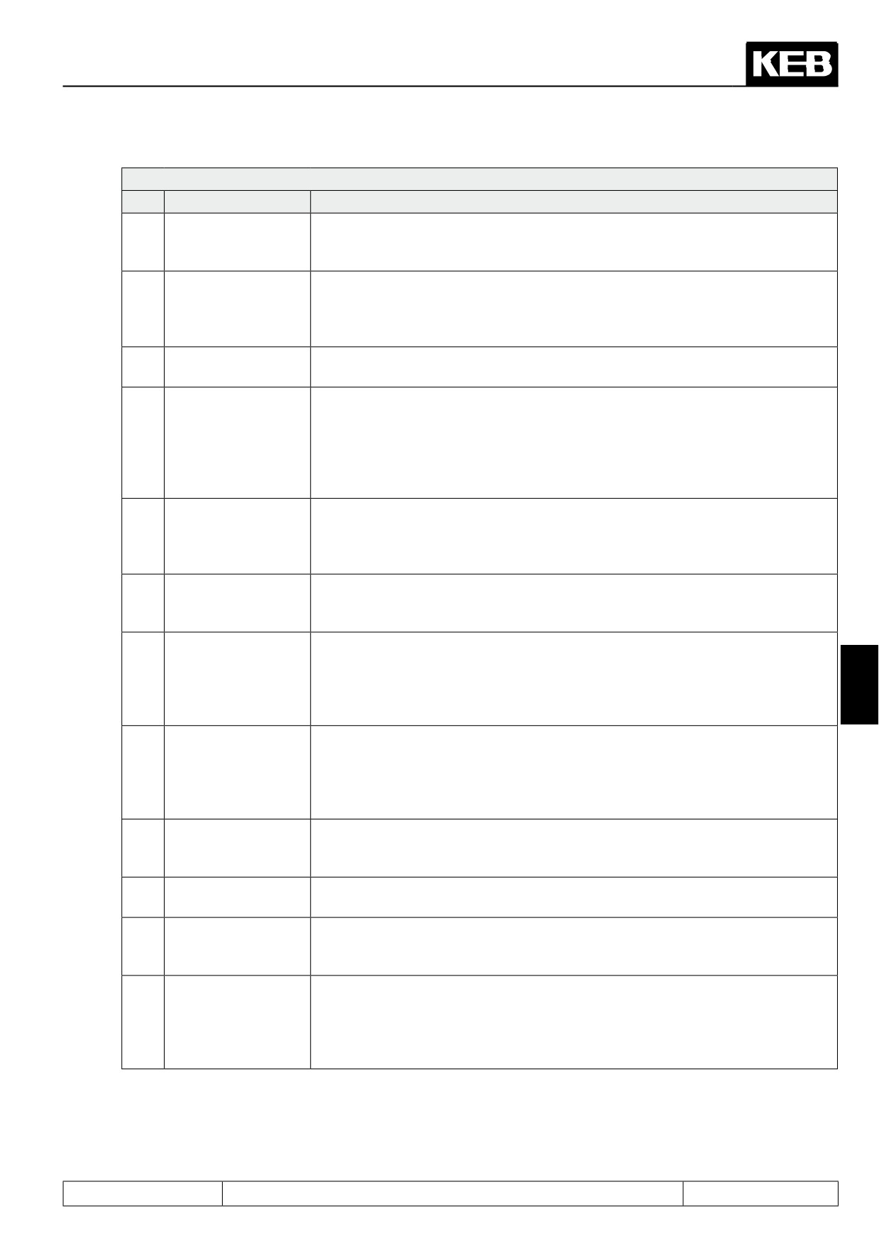
Pn.65 Special functions
Bit
Meaning
Explanation
1: GTR7 function for
0
GTR7 function also available in status "70: standstill (Modulation off)" (LS) *1
LS
With the input selected in Pn.04 "Ext. fault input selection", "Error! undervoltage"
is triggered rather than "Error! external input".This can achieve that, for coupled
drives, all inverters simultaneously go to undervoltage as soon as there is a
1
2: Pn.04 = E.UP
brownout on one of the inverters, and all inverters also execute an automatic
restart simultaneously when the mains voltage returns to the valid range on all
inverters. The undervoltage error from the DC link voltage measurement re-
mains active.
further on next side
Page7.13 - 36
Protective Functions
Pn.65 Special functions
Bit
Meaning
Explanation
The status "13: Power circuit not ready" (nO_PU), which the inverter enters for
4: Behaviour if LT
2
an unpowered power circuit, is not treated as an error. I.e., the switching condi-
not ready
tions 4..6 are not met and the bit 1 in status word "Error" is not set.
GTR7 function also available if the inverter is in an error state. Exception:On
8: GTR7 release on
opening of the hardware control release (terminal X2A.16) and for an unpow-
3
error
ered power circuit (status 13: power circuit not ready), the GTR7 is always swit-
ched off. *1
16: OL2 tempera-
On activation of this bit, the current limit for the overload protection in the lower
4
ture-dependent
speed range (OL2-function) is dependent on the heat sink temperature
The terminal ST causes an immediate hardware switch-off of the GTR7. If the
GTR7 function should also be available in status "0: no control release" (nop),
32: GTR7 function
the software control release must be used (activation via di.36). The GTR7 can
5
for SW nop
then be activated for the status "no control release" with bit 5. Exception: On
opening the hardware control release (terminal X2A.16), the GTR7 is always
switched off.
*1
For switching frequencies above the rated switching frequency, the current limit
64: OL2 Derating li-
for the overload protection in the lower speed range is reduced. On activation
6
miting
of this bit, the inverter reduces the switching frequency to the rated switching
frequency to prevent the error "Overload in standstill" (E.OL2).
The status "2: ERROR! undervoltage" (E.UP) is not treated as an error if the
128: E.UP = no error
7
rotation setting or the control release is missing. I.e., the switching conditions
on nop+LS
4..6 are not met and the bit 1 in status word "Error" is not set.
The status "76: motor de-excitation" (bbL) is not displayed anymore. Advantage:
the cause of the switch-off of the modulation (e.g., error) is visible immediately
256: BBL is not dis-
8
in ru.00 and can be evaluated by an external control. Disadvantage: Since a
played
7
reset of an error is only possible after expiration of the base-block time, it is not
apparent without display when a reset can be executed.
The bit 2 in SY.51 "status word (low) normally shows "Start" if the modulation is
switched on. Exception: If a positioning is aborted via the bit 11 "Termination" in
512: Status termina-
9
the control word, then the status word displays "Stop" as soon as the drive re-
tion = RUN
aches speed 0 (even if modulation is still active). This exception can be revoked
by activation of bit 9.
If this bit is active, the ERROR-bit in status word SY.51 and the switching con-
10
1024: A.XX = error
dition that responds to an error are set in case of a malfunction (Status warning
/ A.XX).
2048: no dig. ST =
the two watchdogs (for operator interface and HSP5) are deactivated by the
11
no E.Bus
input programmed in di.39 "Shutdown ST input selection". *2
A malfunction or error reset is permitted only when the amount of the actual
4096: Error reset at
12
value (ru.07) is smaller than the operating hysteresis(LE.16). This applies also
0
to the automatic restart.
The comparison ru.07 "Actual value display" = ru.01 "Set value display“ (for
status word and condition "constant run“) is continuously executed, even for
8192: Actual value =
13
switched off modulation and during the "speed search“.
setpoint at mod. off
This affects the status word, the timer start and reset conditions, and the swit-
ching condition 20.
Page7.13 - 37
Protective Functions
*1 to bit 0, 3, 5: With the GTR7 (braking transistor), a braking resistor can be connected to the DC link that
absorbs recovered energy when the motor is working as a generator.
By default, the GTR7 is off when the modulation is switched off.
For some applications (e.g., synchronous motor operated in the field weakening range) it is
sensible to leave the GTR7 active for switched off modulation, so that the braking resistor
can be added when the DC link voltage exceeds the value of Pn.69 "GTR7 voltage".
By setting this bit, the GTR7 function is available for the respective inverter state.
*2 to bit 11:
If a drive is controlled via a bus system, and the control release is furthermore switched
via the control word, the two watchdogs (Operator watchdog and HSP5 watchdog) should
be activated so that the drive is stopped on failure of the bus system. However, the drive
can then not be repositioned by hand anymore, since - as long as the bus is down - the
malfunction- or error message of the watchdog remains in force.
With parameter di.39 "Disable dig. ST input selection", an input can already be selected
with which the digital setting of the control release (i.e., setting via di - parameter or the
control word) can be deactivated. With that, only the terminal ST (X2A.16) is operative, and
the regulation of the control release can again occur via the digital input alone.
If this bit is set, the two watchdogs are also deactivated with the selected (in di.39) input. If
a response with automatic restart is now selected for the watchdog error, the malfunction
automatically resets and the drive can be used in manual operation.
Page7.13 - 38
Parameter Sets
7.1
Operating and appliance date
1.
Introduction
7.2
Analog in- and outputs I
2.
Summary
7.3
Digital in- and outputs
3.
Hardware
7.4
Setpoint-, rotation- and ramp adjustment
Motor data and controller adjustments of the asynchronous
7.5
4.
Operation
motor
Motor data and controller adjustments of the synchronous
7.6
motor
Selection of Operating
5.
Mode
7.7
Speed control
6.
Initial Start-up
7.8
Torque display and -limiting
7.9
Torque control
7.
Functions
7
7.10
Current control, -limiting and switching frequencies
8.
Error Assistance
7.11
Speed measurement
9.
Project Design
7.12
Positioning and synchronous control
7.13
Protective functions
10. Networks
7.14
Parameter sets
11. Parameter Overview
7.15
Special functions
12. Annex
7.16
CP-Parameter definition
Page7.14 - 1
Parameter Sets
7.14.1
Non-programmable parameters
7.14 - 3
7.14.2
Security parameters
7.14 - 3
7.14.3
System Parameters
7.14 - 3
7.14.4
Indirect and direct set-addressing
7.14 - 4
7.14.5
Copying of parameter sets via keyboard (Fr.01)
7.14 - 4
7.14.6
Copying of parameter sets via bus (Fr.01, Fr.09)
7.14 - 5
7.14.7
Parameter set selection
7.14 - 8
7.14.8
Locking of parameter sets
7.14 - 12
7.14.9
Parameter set ON/OFF delay (Fr.05, Fr.06)
7.14 - 13
Page7.14 - 2
Parameter Sets
7.14 Parameter sets
The KEB COMBIVERT contains 8 parameter sets (0...7), i.e. all programmable parameters are available 8
times in the inverter and independent of each other they can be assigned with different values. As a lot of
parameters in the parameter sets contain the same value, it would be relatively complicated to change every
parameter in each set individually. In this section it is described, how one copies whole parameter sets, locks
them, selects them and reinitializes the inverter.
7.14.1Non-programmable parameters
Certain parameters are not set-programmable, as their value must be the same in all sets (e.g. bus address or
baud rate). For an easy identification of these parameters the parameter set number is missing in the parameter
identification.
For all non-programmable parameters the same value is valid independent of the selected parameter
set!
Following parameters are non-programmable:
Sy Parameters
Pn.00...18/ 23/ 27/ 29/ 42/ 44...60/ 62...66/ 68/ 69/ 74…81
ru parameters
uF.08/ 12...15/ 18 (uF.09 at F5-S) / 18…23
Ec parameters
ud.01...17/ ud.22…31 (all at F5-S)
AA parameters
Fr.02...04/ 07/ 09/ 11 (Fr.10 at F5-S)
di parameters
An.00...04/ 10...14/ 20...24/ 41...56
In parameters (exception: In.25)
LE.16-27
dr parameters (not at F5-S)
cn.03/ 11...13
7
oP.19/ 20/ 50/ 53...58/ 60…63/ 65…68/ 74
dS.00...01 (only F5-S)
PS.02...04/ 10...27/ 29...31
7.14.2Security parameters
The security parameters contain the Baud rate, inverter address, hours/meter, control type, serial-/customer
number, trimming values and error diagnosis. They are not overwritten while copying parameter sets from the
default set.
Sy.02/ 03/ 06/ 07/ 11
ru.40/ 41
ud.01/ 02
Fr.01
In.10...16/ 24...31
7.14.3System Parameters
The system parameters contain the motor and encoder data.
dr parameters
Pn.61/ 67
cS.00...19...22
dS.00...01/ 13
Ec.01...07/ 11-27/ 36...38
Fr.10
Page7.14 - 3
Parameter Sets
7.14.4Indirect and direct set-addressing
During indirect set addressing the parameter values are indicated and edited to the adjustment of the set indi-
cator (Fr.09). The direct set addressing enables the display or writing of a parameter value independent of the
set indicator directly into one or several parameter sets. The direct set programming is only possible with bus
operation.
7.14.5Copying of parameter sets via keyboard (Fr.01)
Adjust target set
Adjust source set
A✳ Fr· 1
ini_A
0. Fr. 1
ini_S
▲
1. Fr. 1
dEF_A
▲
DOWN
DOWN
2. Fr. 1
dEF_S
3. Fr. 1
0
〉 with Func. to the source
〉
with Funct.
4. Fr. 1
1
UP
UP
5. Fr. 1
2
▼
▼
6. Fr. 1
3
7. Fr. 1
4
5
6
7
With the keys UP/Down and at flashing
The source set is adjusted with the keys
point the target set 0...7 is adjusted in
UP/Down. The copying process is star-
addition to the parameter set number.
ted with „Enter“. Copying is only possi-
The active (A) parameter set must not
ble with opened control release or error,
be adjusted as target set while copying.
otherwise „I_oPE“ appears in the display
If the target set is > 0, only the program-
(invalid operation).
mable parameters are overwritten!
After copying „PASS“ appears in the dis-
play and could be erase by „ENTER“.
Page7.14 - 4
Parameter Sets
7.14.6Copying of parameter sets via bus (Fr.01, Fr.09)
In case of indirect set addressing at Bus operation two parameters are responsible for the copying of parame-
ter sets. Fr.09 defines the target set. Fr.01 defines the source parameter set and starts the copying process.
In the case of direct set programming the source set (Fr. 01) is copied into the selected parameter sets. The
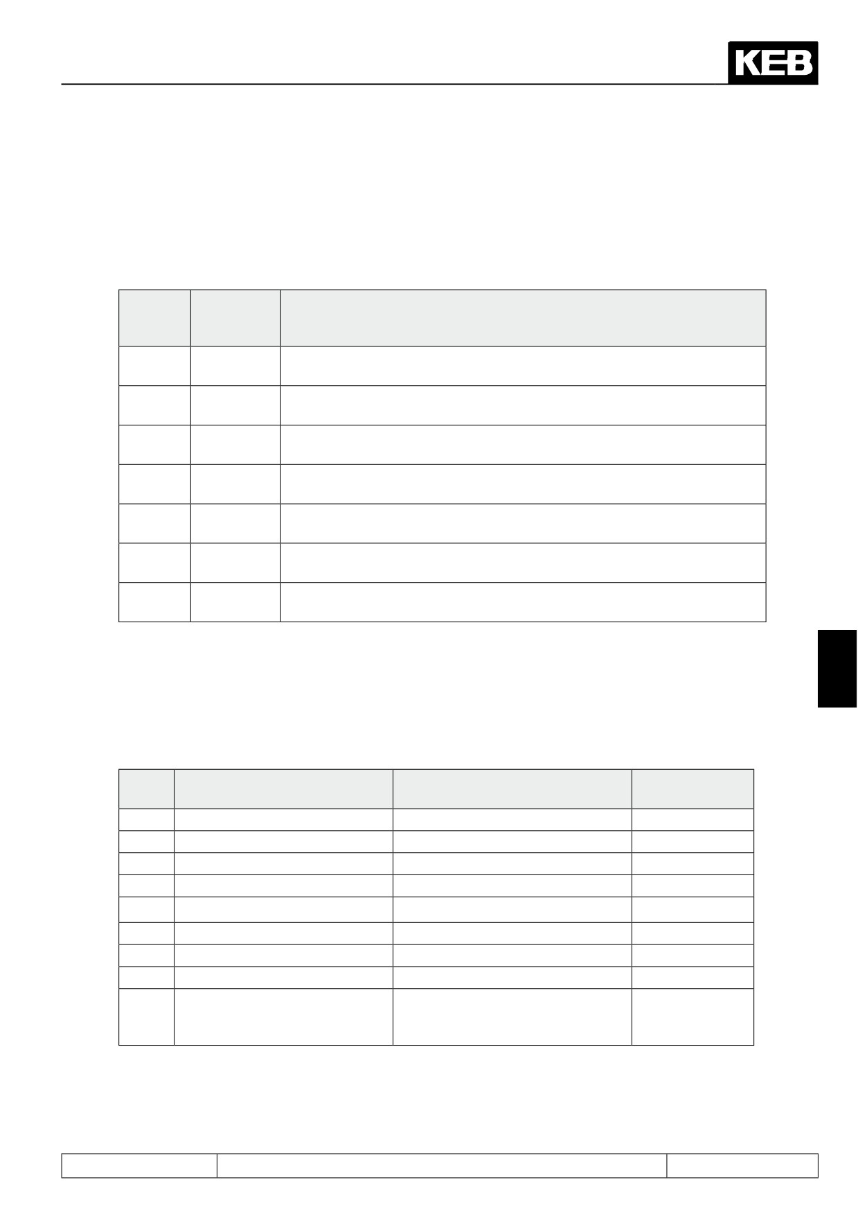
following copying actions can be practised:
Target
Source set
Action
set
Fr.01
Fr.09
0...7
0...7
All programmable parameters (System parameters too) of the source set
are copied into the target set.
0
-1: dEF_S
Default values are copied into all parameters of set 0 (with exception of
System and Security parameters).
1...7
-1: dEF_S
Default values are copied into all programmable parameters of the target
set (with the exception of System and Security parameters).
All
-2: dEF_A
Default values are copied into all parameters of all sets (with the exception
of System and Security parameters).
0
-3: ini_S
Default values are copied into all parameters of set 0 (with the exception of
Security parameters).
1...7
-3: ini_S
Default values are copied into all programmable parameters of the target
set (with the exception of Security parameters).
All
-4: ini_A
Default values are copied into all parameters of all sets (with the exception
of Security parameters).
By loading the factory setting all definitions defined by the mechanical engineer are reset! This can comprise
the terminal assignment, set changeover or operating states. Before loading the default set it is to be ensured
7
that no unintended operating states occur.
Custom-specific default values
Value
Source default values
Copied parameters
Target sets
Fr.01
-1
KEB
Customer parameters
selected
-2
KEB
Customer parameters
all
-3
KEB
Customer and system parameters
selected
-4
KEB
Customer and system parameters
all
-5
custom-specific
Customer parameters
selected
-6
custom-specific
Customer parameters
all
-7
custom-specific
Customer and system parameters
selected
-8
custom-specific
Customer and system parameters
all
-9
Storing of the current parame-
Customer and system parameters
all
ter setting as custom-specific
default values.
The values -5 to -8 are corresponding to the previous values -1 to -4 referring to the copied parameters and
target sets. They differ only in the default value source.
Value -9 enables storing of the current parameter setting as custom-specific default values. The values of all
customer and system parameters are stored in all sets thereby.
Page7.14 - 5