KEB COMBIVERT F5-A,-E,-H 4.0. APPLICATION MANUAL (2008) - page 22
Special Functions
Timer reset condition (LE.20 / LE.25)
According to the following table the conditions can be defined under which the timer is reset in addition to the
inputs. The individual conditions are OR-operated.
Bit -No.
Decimal value
condition
0
1
Modulation on
1
2
Modulation off
2
4
Actual value = Setpoint va-
lue
3
8
Change of parameter set
4
16
Power-On-Reset
Timer display (ru.43 / ru.44)
ru.43 / ru.44 displays the actual counter reading dependent of the adjusted clock source (LE.21 / 26). By wri-
ting on ru.43 / 44 the counter can be set to a value. If the clock source is changed during the running time the
counter content is maintained but is interpreted according to the new clock source.
Comparison level 0...7 (LE.00...LE.07)
LE.00...LE.07 define the level for the switching conditions 37 / 38 ("Timer > Level").If the timer exceeds the
adjusted value the switching condition is set. A level in the range of
-10.737.418,24 to 10.737.418,23 can be
adjusted. But only values of 0...655,35 are sensible for the counter.
7.15.5Brake Control
For applications in the areas lifting and lowering, or other applications requiring the use of a brake, the control
of the brake can be taken over by the KEB frequency inverter.
To that end, the brake control must be activated in parameter Pn.34 "Brake control mode", and a transistor or
relay output must be connected to the function "18: Brake control". The output becomes active if the brake is
to be ventilated.
Page7.15 - 12
Special Functions
7.15.5.1
Brake control mode
With Pn.34, the status display during the brake handling can be set and a monitoring function can be activa-
ted.
The brake control is set-programmable.
Pn.34: Brake control mode
Value
Explanation
0: off
Brake control deactivated.
Brake control activated. Progress message "85: Close brake" (bon) or "86: Open bra-
1: with display
ke" (boFF).
2: without display
Brake control activated. No brake-specific status messages.
Brake control activated. Progress message "85: Close brake" (bon) or "86: Open bra-
3: with phase check /
ke" (boFF). Check whether all 3 inverter output phases can be powered. If one phase
with display
is missing, "56: ERROR! Brake control" (E.br) is triggered.
Brake control activated. No brake-specific status messages. Check whether all 3 in-
4: with phase check /
verter output phases can be powered. If one phase is missing, "56: ERROR! Brake
without display
control" (E.br) is triggered.
7.15.5.2
Monitoring of the brake control
Pn.43 "Min. load brake control"
With Pn.43 "Min. load brake control", a further monitor for the brake control can be activated.
For the monitoring of the utilisation acceptance through the inverter a minimal utilisation level can be adjusted
in this parameter.
7
If the brake is to be opened on start at the end of the pre-magnetising time (Pn.35), the load factor may not be
smaller than the adjusted level. Otherwise the error E. br is triggered. Reaching the hardware current limit the
error E.br is triggered too. The current is monitored only at this time (directly before the opening of the brake).
The monitoring is deactivated when Pn.43 is set to 0.
Pn.42 "Brake check input selection"
Between the end of the brake closing period (Pn.40) and the beginning of the break opening period (Pn.36), the
brake must always be closed. If the input becomes (or is) active during this phase, E.br is triggered.
Similarly, from the end of the brake opening period (Pn.36) to the end of the brake delay time (Pn.39), the brake
must always remain ventilated. If the input becomes (or is) inactive in this phase, E.br is also triggered.
With this input, e.g., a protection monitoring could be executed.
Page7.15 - 13
Special Functions
7.15.5.3
Sequence of the brake control
The sequence of the brake control is defined by five times, two for the opening and three for the closing of the
brake.
open brake
The opening of the brake is started when the control release is closed and the command to start the drive is
received.
In vector controlled operation, this is the activation of the direction of rotation, the setpoint speed has no effect.
That means: the brake is opened as well on setting the speed setpoint value = 0.
During positioning, the opening of the brake is triggered, e.g., by a "Start positioning" or a "Start approach to
reference point" command
•
Pn.35: premagnetising time
The pre-magnetisation time serves to build up a holding torque to minimise the "stall out" of the drive
during ventilation of the brake.
The adjustment of this time and of the brake control-starting value (Pn.37) depends on the mode
(V/F characteristic controlled, vector controlled, etc.) and is described in the items 7.15.5.4 and 7.15.5.5.
•
Pn.36: Brake release time
With begin of the brake ventilation time, the signal to open the brake is issued.
During the brake ventilation time, in which the brake is loosened mechanically, the speed set value (ru.01)
is not yet applied, instead, the brake control-starting value (Pn.37) is still in effect. For vector controlled
systems, Pn.37 must contain the value 0 rpm for synchronous as well as for asynchronous motors.
close brake
The closing of the brake is triggered by disabling the direction of rotation (speed control), reaching of the target
position (positioning), or switching off the modulation (opening of the control release or error).
If the modulation is switched off, the break control output is immediately deactivated so that the brake closes.
In all other cases, the sequence is as follows:
•
Pn.39: Brake delay time
After switching off of the rotation setting, the drive runs to the stopping speed Pn.41 (for vector controlled
drives, this parameter must contain the value 0 rpm) and waits there for the duration of the brake delay
time.
•
Pn.40: Brake closing time
Afterwards, the brake control output is deactivated and the brake takes over the load during the brake
closing time. The inverter remains at the stopping speed Pn.41 during this time.
•
Pn.38: Brake fadeout time
After expiration of the brake closing time (Pn.40), the fadeout time expires. During this time, the current
is lowered to 0. After expiration of the fadeout time, the modulation remains switched on for another 100
ms.
Thereby, the noise that can occur in the motor during a jolt-like shutdown of the current can be preven-
ted.
After the current has been drained, the inverter changes into the status "70: standstill (Modulation off)"
(LS)
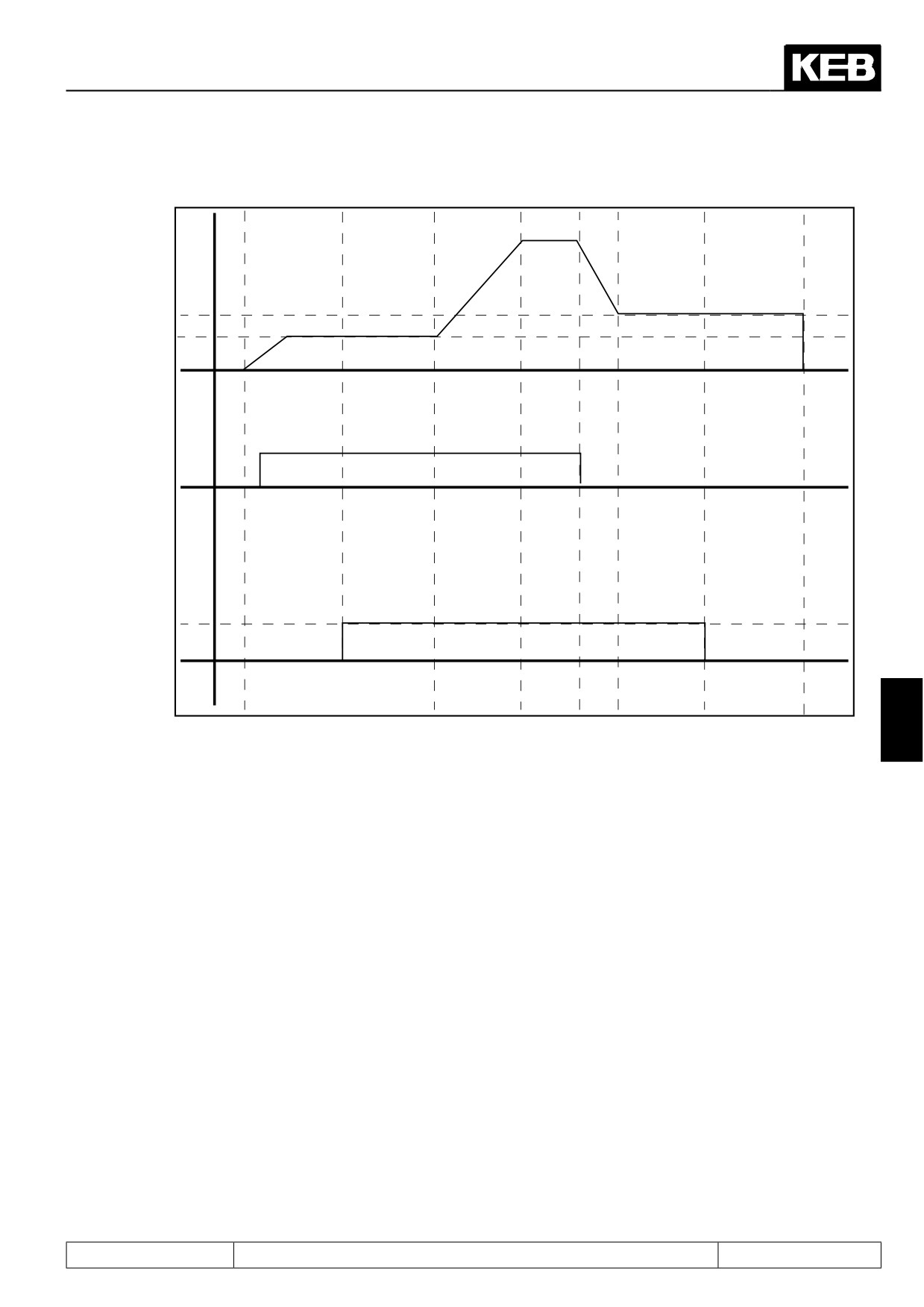
The following figure shows the sequence of the brake control without fadeout time. In vector controlled system,
the start- and the stop-value (Pn.37 / Pn.41) must be set to 0 rpm.
Page7.15 - 14
Special Functions
Figure 7.15.5.3 Brake control
Set value
(ru.01)
Actual speed
Stop value
(Pn.41)
Start value
(Pn.37)
Set direction
of rotation for
Inverter
boff
boff
boff
bon
bon
LS
facc
facc
fdec
LS
state
facc
fcon
fcon
fcon
fcon
opened
Brake
closed
Premagneti-
Brake re-
Brake delay
Brake clo-
sing time
lease time
time
sing time
Pn.35
Pn.36
Pn.39
Pn.39
7
7.15.5.4
Brake control / vector controlled
Premagnetisation and delay time
In vector controlled operation, the drive builds up torque even at the setpoint speed 0. Therefore, no starting or
stopping speed is required (Pn.37 = Pn.41 = 0 rpm).
Thus can the pre-magnetisation time Pn.35, too, be set to zero. The time the drive requires to build up the flux
is always waited for, until the output for loosening the brake is set.
Exception:
If the bit 7 "Wait for magnetisation" in dS.04 "Flux- / rotor adaption mode" is set to "0: off", a pre-magnetisation
time must be parametrised for flux buildup. This setting is permissible only for operation without motor model.
Since, independent of the chosen deceleration ramp, the brake closing time only starts when the actual speed
reaches the value of the stopping speed (= 0 rpm), no brake delay time has to be waited out.
In some applications, however, the brake delay time is used to save time.
If the output for brake control has been deactivated once, the complete brake handling (Brake closing time +
fadeout time + brake opening time) must be executed for a new start of the drive.
By setting a brake delay time, the collapse of the brake can be suppressed for a quick succession of starts (e.g.,
for positioning). Only when the drive remains stationary for a longer period, the brake is closed.
Page7.15 - 15
Special Functions
Optimization of the load transfer
In vector controlled operation, there are another two special functions that optimise the load transfer to the
drive:
•
speed-dependent Ki for the speed controller
For the load transfer, an enormous speed rigidity is often required for hoists or lifts so that the opening of
the brake and the transfer of the load by the inverter is not felt. This rigidity can be achieved by a very large
"K-increase" (cS.10) for the speed controller.
This increase is normally reversed again over an adjustable speed range. For extremely large KI-incre-
ases, this slow reversal cannot be used since the speed controller is then too vibration-prone.
By input of the value "-1: Brake release" in parameter corner speed for max. KI (cS.11), one can achieve
that the "KI-increase" is immediately set to 0 at the end of the brake opening time.
•
Brake precontrol
Without precontrol, the drive must first move, i.e., a system deviation must be built up so that the controller
provides a counter torque.
With the precontrol, the speed controller is preloaded with a torque at the beginning of the brake opening
time. To avoid "stall out", this torque is, in the ideal case, equal to the load to be taken over by the brake.
The precontrol value is set with a ramp within 1/5 of the brake ventilation time.
The function is activated by selecting in Pn.70 "Brake precontrol torque source" how the precontrol value
is to be defined.
Pn.70: Brake pretorque source
Value
Function
0: off
Precontrol function off
1: analog REF
Setting of the precontrol torque in % of the rated torque via the analog channel REF or
2: analog Aux
AUX. The analog signal can come from, e.g., a load weighing setup in a lift cabin.
Setting of the precontrol torque in % of the rated torque via parameter Pn.71 "Pretorque
3: digital % (Pn.71)
reference setting %"
Example: Let a lift be equipped with a counterweight so that for a half-loaded cabin, no holding torque must
be expended.
For an empty cabin, the load weighing setup provides a signal of 0%.
To hold the cabin, the motor requires + rated torque .
For a fully loaded cabin, the load weighing setup provides a signal of 100%.
To hold the cabin, the motor requires + rated torque .
Let the signal from the load weighing setup be connected to AN2, which serves as the AUX-
input.
I.e.:
a signal of 0% on AN2 shall produce a precontrol value of 100%
a signal of +100% on AN2 shall produce a precontrol value of -100%.
"AN2 offset X" (An.16) be equal to 0%, "AN2 lower limit" (An.18) = -100%, and "AN2 upper limit"
(An.19) = 100%
The formula for amplification and offset setting is then for AN2:
Output signal = "AN2 gain" (An.15) * input signal + "AN2 offset Y" (An.17)
This gives, for "AN2 offset Y" = 100% and for "AN2 gain" = -2
Page7.15 - 16
Special Functions
Operation without encoder
Since the settings range of the drive is limited during operation without encoder, no brake handling should be
used for SCL as well as for ASCL.
For SCL, the parameters "Pre-magnetisation time" (Pn.35) and "Brake ventilation time" (Pn.36) are used for the
alignment of the motor with a DC current (see chapter 7.6.3.4 SCL / standstill and starting phase)
7.15.5.5
V/F characteristic controlled operation
Start reference (Pn.37), stop reference (Pn.41)
In V/F characteristic controlled operation, start and stop values must be set to hold the load in standstill and,
respectively, reach standstill after deceleration, so that the brake can collapse again.
The adjustable start/stop value stands in direct connection with the necessary holding torque. A preset value
can be obtained according to the following formula:
(synchronous speed- rated speed) x required holding torque
Start- and, respectively,
——————————————————————————————
stop value =
Rated torque
Based on these value, an adaption to the particular application must be made since other values, e.g., the
boost, also have an effect on the behaviour during load transfer.
Example: Let a 4-pole motor have a rated frequency of 50 Hz and a rated speed of 1460 rpm.
The synchronous speed of the motor is thereby = 1500 rpm and for rated torque and nominal voltage, the slip
speed amounts to 1500 - 1460 = 60 rpm.
7
If setting a starting value (Pn.37) of 60 rpm, the drive should be able to provide rated torque when loosening
the brake.
Premagnetising time (Pn.35)
So that a torque can be built up, the flux in the motor must have been built up. With beginning of the pre-ma-
gnetisation time, the motor is powered. This time must be long enough for the motor to build up its flux.
Depending on the motor, this time can be between approximately 100 ms (small power) and fractions of a se-
cond (motors with large power).
Brake delay time (Pn.39)
In V/F characteristic controlled operation, the speed follows the predefined deceleration ramp not quite exactly.
After completion of the deceleration ramp, there must therefore be a delay time, to mask dynamic effects.
Page7.15 - 17
Special Functions
7.15.6
Wobbel function
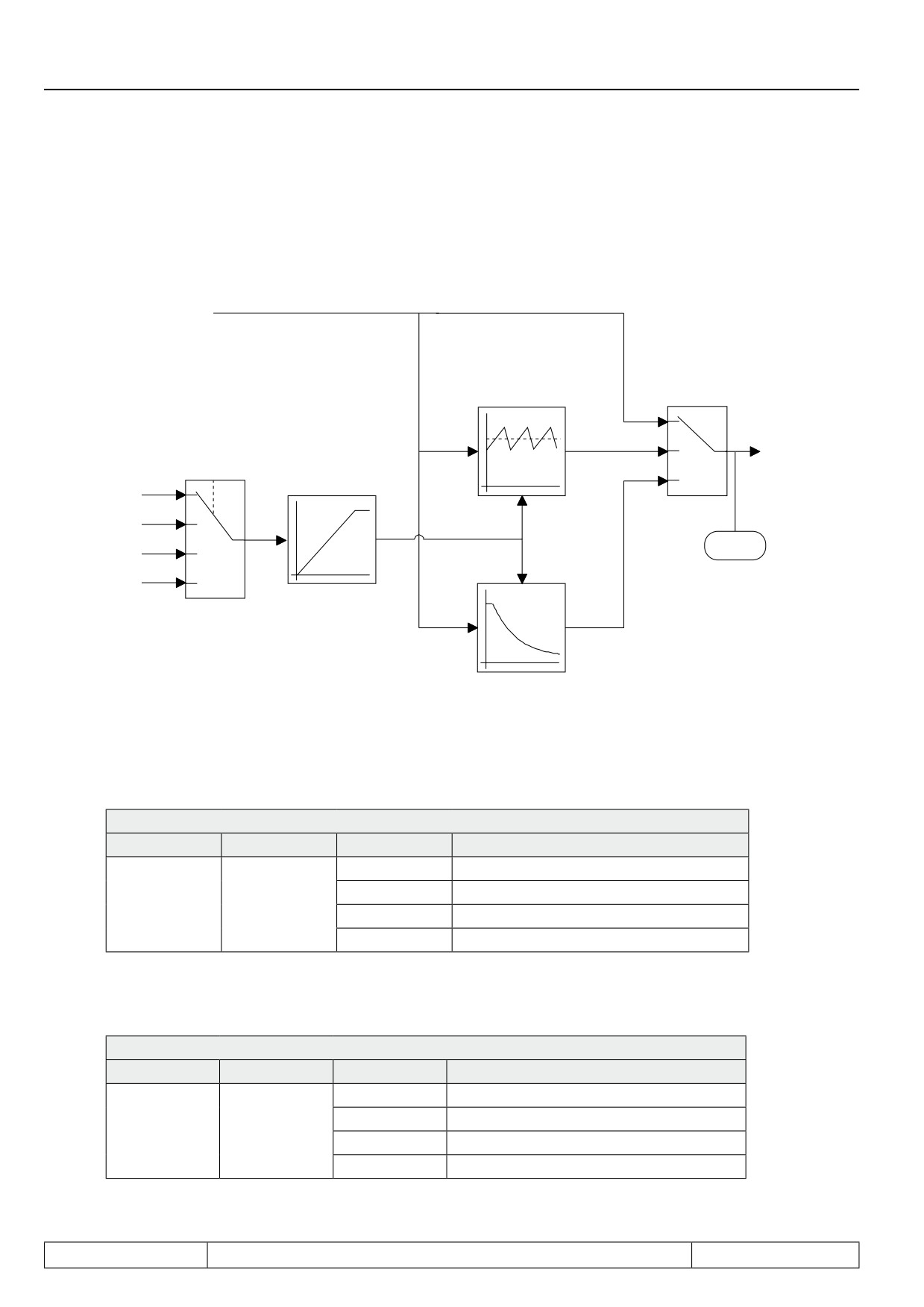
The wobble generator enables in period and amplitude changeable sawtooth process of the setpoint. It is acti-
vated with the parameter oP.44 Bit 0...3 = "1".
7.15.6.a Additional funktion: Wobbel generator
Ramp output value
Wobbel generator
oP.44
oP.47, 48
Bit 0...3
0
1
Setpoint va-
oP.44
Bit 4...7
2
lue
0
oP.46
AN1 (ru.28)
1
Amplitude
AN2 (ru.30)
2
ru.02
AN3 (ru.32)
Diameter signal
3
digital (oP.45)
oP.49
Diameter correction
Ext. function / Mode (oP.44 Bit 0...3)
Two different functions can be activated with oP.44 bit 0...3. The value is to be added to Bit 4...7.
oP.44: Ext. function mode / source
Bit
Meaning
Value
Function
0
no external function activated
1
Wobbel generator active
0...3
mode
2
Diameter correction (see 7.15.8)
3...15
reserved
Ext. function / Source (oP.44 Bit 4...7)
The input source for the functions is determined with oP.44 Bit 4...7. The value is to be added to Bit 0...3.
oP.44: Ext. function mode / source
Bit
Meaning
Value
Function
0
Analog input AN1
16
Analog input AN2
4...7
source
32
Analog input AN3
48
digital setting with oP.45
Page7.15 - 18
Special Functions
Ext. function digital source (oP.45)
If the value "49" (sweep function with digital specification) is adjusted in oP.44, the sweep amplitude is preset
with oP.45 within the range of 0...100 %.
Ext. function acceleration/deceleration (oP.46)
With oP.46 a time can be preset between 0,00...20,00 s, with which the sweep amplitude rises/falls. The entered
value refers to a sweep amplitude of 100 %.
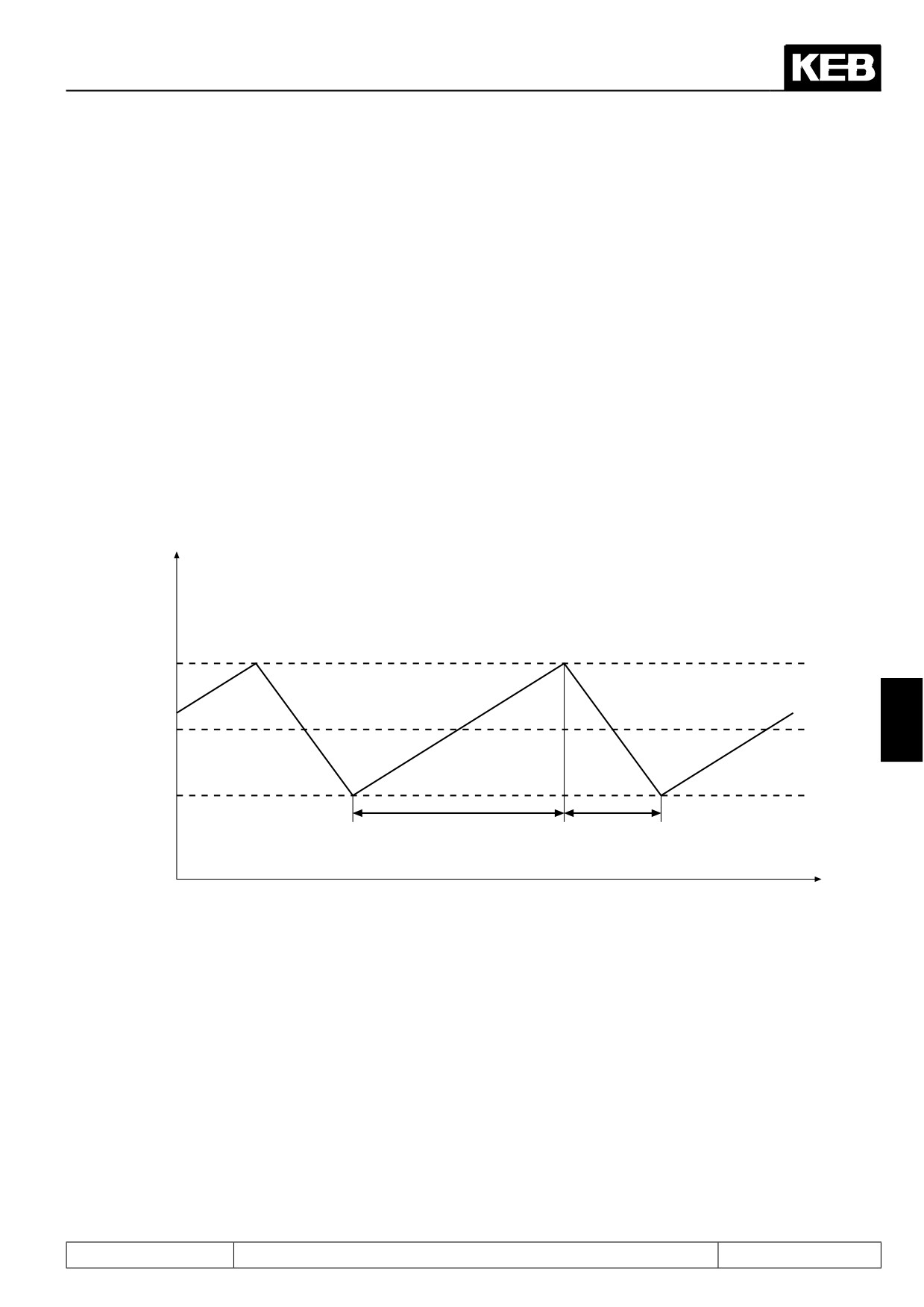
Sweep generator acceleration time (oP.47), deceleration time (oP.48)
With oP.47 the acceleration time and with oP.48 the deceleration is adjusted in each case within the range of
0...20,00 s. Together the two parameters result in the period duration of the wobbel period.
7.15.6.b Acceleration and deceleration times of the wobbel generator
F
Ampl.
f
+----------
set
2
fset
7
Ampl.
fset -----------
2
oP.47
oP.48
t
Page7.15 - 19
Special Functions
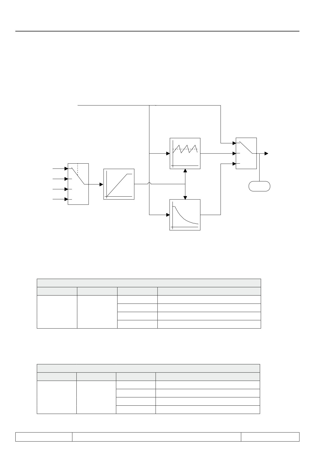
7.15.7Diameter correction
Through the use of the diameter correction the tool path feed rate of a winding product can be kept constant at
changing diameter of the reel bale.
7.15.7 Additional function: Diameter correction
Ramp output value
Wobbel generator
oP.44
oP.47, 48
Bit 0...3
0
Setpoint
1
oP.44
value
Bit 4...7
2
0
oP.46
AN1 (ru.28)
1
Amplitude
AN2 (ru.30)
2
ru.02
AN3 (ru.32)
Diameter signal
3
digital (oP.45)
oP.49
Diameter correction
Ext. function / mode (oP.44 Bit 0...3)
Two different functions can be activated with oP.44 bit 0...3. The value is to be added to Bit 4...7.
oP.44: Ext. function mode / source
Bit
Meaning
Value
Function
0
no external function activated
1
Wobbel generator (see chapter 7.15.7)
0...3
mode
2
Diameter correction activated
3...15
reserved
Ext. function / Source (oP.44 Bit 4...7)
The input source for the functions is determined with oP.44 Bit 4...7. The value is to be added to Bit 0...3.
oP.44: Ext. function mode / source
Bit
Meaning
Value
Function
0
Analog input AN1
16
Analog input AN2
4...7
source
32
Analog input AN3
48
digital setting with oP.45
Page7.15 - 20

Special Functions
Ext. function digital source (oP.45)
If the value "50" (sweep function with digital specification) is adjusted in oP.44, the diameter signal can be pre-
set with oP.45 within the range of 0...100 %.
Diameter correction dmin/dmax (oP.49)
The diameter signal is evaluated within the range of 0 % to 100%. Values < 0% are set to 0%, values > 100%
are limited to 100%.
The diameter signal of 0% corresponds to the minimum diameter of the reel bale (dmin). The output frequency/
speed of the ramp generator is not changed in this case. A diameter signal of 100% corresponds to the maxi-
mum diameter of the reel bale (dmax). In order to be able to calculate the frequency/speed change the program
requires the ratio of minimum to maximum diameter (dmin/dmax).
The ratio of minimum to maximum diameter (dmin/dmax) is preset by way of oP.49 and can be adjusted within the
range of 0,010...0,990 with a resolution of 0,001.
The corrected output frequency of the ramp generator is determined as follows:
fn_Ramp
fn_presetting:
—————————
1+DS·(1/oP.49-1)
fn_Ramp:
Output frequency/speed of ramp generator
fn_presetting: Corrected output frequency/speed
DS:
Diameter signal 0 - 100% (0 to 1)
7
oP.49:
(dmin/dmax)
Ext. function acceleration/deceleration (oP.46)
The rate of change of the diameter signal can be limited by a ramp generator. By way of oP.46 the time can be
preset within the range of 0,00...20,00 s, which is required for a signal difference of 0...100%.
7.15.8Analog Setting of Parameter Values
With this function it is possible to preset parameter values analog. The AUX-function or the motor-poti function
can be adjusted as source.
Analog parameter setting source (An.53)
This parameter determines whether the analog parameter setting occurs via the motor-poti or the aux-func-
tion.
An.53: Analog parameter setting source
Value
Function
0
AUX
1
Motorpoti function
Page7.15 - 21

Special Functions
The Bus-address of the parameter, that is to be adjusted in analog mode, is adjusted here (see chapter 11).
Following parameters can be adjusted.
Analog parameter setting destination (An.54)
uF.01 / 07
cn. 04 / 05 / 06
An.32 / 37 / 42 / 48
LE.00 / 01 / 02 / 03 / 04 / 05 / 06 / 07
cS.06 / 09
Ec.4 / 14
PS.31 / 33
In case an invalid parameter address is selected, the message "IdAtA" (or "data invalid" at COMBIVIS) is output
and the setting is ignored.
Analog parameter setting offset (An.55)
Defines the parameter value, that adjusts itself at 0 % analog parameter setting. The parameter value must be
entered with the internal standardization of the target parameter.
Desired value of target parameter
Value to be adjusted = --------------------------------------------------------
Resolution of target parameter
Analog parameter setting max. value (An.56)
Defines the parameter value, that adjusts itself at 100 % analog parameter setting. The parameter value must
be entered with the internal standardization of the target parameter.
Analog parameter setting set pointer (An.57)
An.57 determines the parameter set which edited the selected parameter. If a programmable parameter is ad-
justed as target parameter, the adjusted set in An.57 is edited.
An.57: Analog parameter setting set pointer
Value
Function
-1
active set is edited
0...7
adjusted set is edited
If a non-programmable parameter is adjusted as target parameter, it is always edited in set 0 independent on
An.57.
Page7.15 - 22
CP-Parameter Definition
7.1
Operating and appliance date
1.
Introduction
7.2
Analog in- and outputs I
2.
Summary
7.3
Digital in- and outputs
3.
Hardware
7.4
Setpoint-, rotation- and ramp adjustment
Motor data and controller adjustments of the asynchronous
7.5
4.
Operation
motor
Motor data and controller adjustments of the synchronous
7.6
motor
Selection of Operating
5.
Mode
7.7
Speed control
6.
Initial Start-up
7.8
Torque display and -limiting
7.9
Torque control
7.
Functions
7
7.10
Current control, -limiting and switching frequencies
8.
Error Assistance
7.11
Speed measurement
9.
Project Design
7.12
Positioning and synchronous control
7.13
Protective functions
10. Networks
7.14
Parameter sets
11. Parameter Overview
7.15
Special functions
12. Annex
7.16
CP-Parameter definition
Page7.16 - 1
CP-Parameter Definition
7.16.1
Survey
7.16 - 3
7.16.2
Assignment of CP-parameters
7.16 - 4
7.16.3
Example
7.16 - 6
7.16.4
Display standardization
7.16 - 7
7.16.5
Variable standardization
7.16 - 9
Page7.16 - 2
CP-Parameter Definition
7.16 CP-parameter definition
Once the development stage of a machine is completed, usually only a few parameters are required for the
adjustment or the control of the inverter. To make the handling easier and the user documentation more un-
derstandable as well as to increase the safety of operation against unauthorized access, the possibility exists
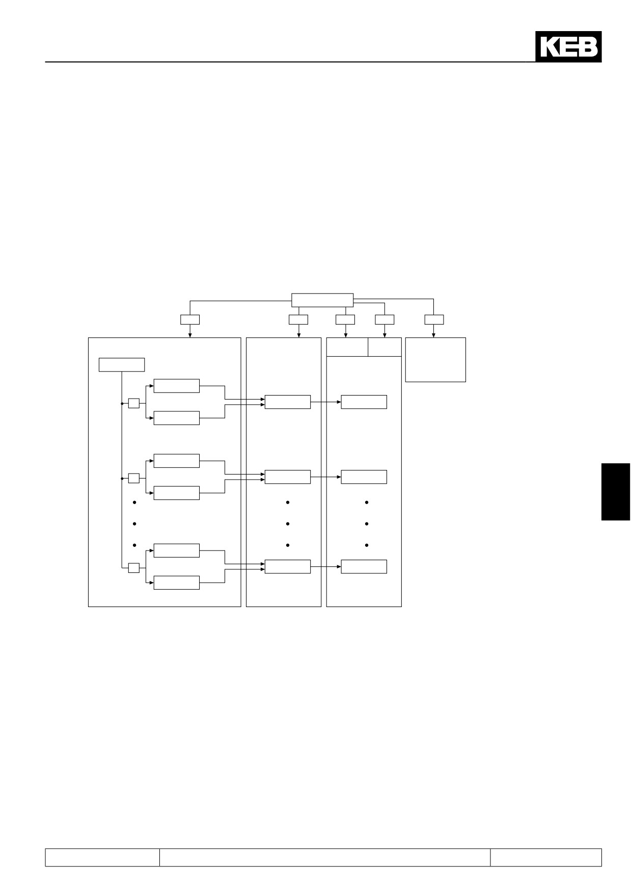
to create the one user surface with the CP-parameters. For that purpose 37 parameters (CP.00...CP.36) are
available, 36 of them (CP.01...CP.36) are free for assignment.
7.16.1Survey
Fig. 7.16.1
Definition structure
Password
CP.0 / ud.1
440
330
200
100
500
Read /
Read
Application mode
Service mode
Write
only
Drive mode
ud.15
CP-mode
Address
ud.16
1
ru.3
CP.1
Set / norm
ud.17
Address
ud.16
2
ru. 1
CP.2
Set / norm
ud.17
7
Address
ud.16
36
An.4
CP.36
Set / norm
ud.17
With ud.15 the CP-parameter that is to be edited is determined. With ud.16 and ud.17 the CP-parameter is
defined through its address and the respective set. Depending on the adjusted password (CP.0 or ud.1)
- the adjusted parameter is directly displayed in the Service Mode
- the adjusted parameter is displayed as CP-parameter in the CP-Mode
Parameter CP.0 is not programmable, it always contains the password input. If the inverter is in the application
mode or service mode ud.1 is used for the password input.
The parameters ud.15...17 as well as Fr.1 are not permitted as CP-parameter and are acknowledged as invalid
parameter address. When entering an invalid parameter address the parameter is set to „oFF“ (-1). The appro-
priate CP-parameter is not displayed at this setting.
Page7.16 - 3
CP-Parameter Definition
7.16.2Assignment of CP-parameters
CP selector (ud.15)
With ud.15 the CP-parameter to be programmed is adjusted in the range of 1...36. CP.0 is not adjustable.
CP address (ud.16)
ud.16 determines the parameter address (see chapter 11) of the parameter to be displayed:
ud.16
CP-address
Invalid or not exist parame-
ter addresses are ignored with
-1: Parameter not used
„Data invalid“.
0...32767: Parameter address
CP set norm (ud.17)
ud.17 determines the set, the addressing and the standardization of the parameter to be displayed. The para-
meter is bit-coded. The individual bits are decoded as follows:
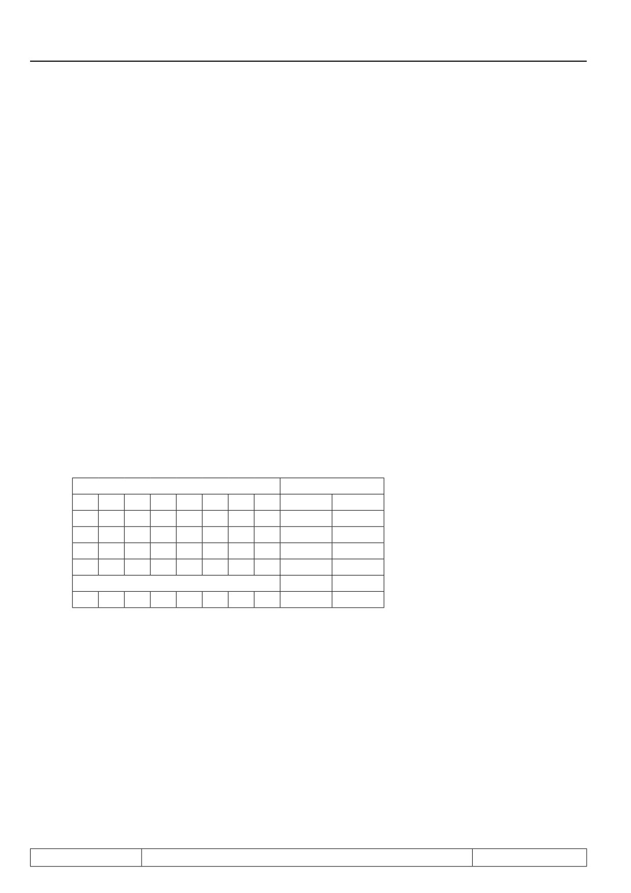
Determination for direct set addressing
Bit 0...7 determines the set selection for direct set programming, i.e. all selected sets contain the same value,
which is defined by the CP-parameter. If direct set programming (Bit 8, 9) is selected at least one set must be
selected as otherwise an error message is triggered in the cp mode.
Bit
7
6
5
4
3
2
1
0
Value
Set
0
0
0
0
0
0
0
0
0
no
-> Data invalid, if Bit 8 and 9 = 0
0
0
0
0
0
0
0
1
1
0
0
0
0
0
0
0
1
0
2
1
0
0
0
0
0
1
0
0
3
0+1
1
1
1
1
1
1
1
1
255
All
Page7.16 - 4
CP-Parameter Definition
Determination of set addressing mode
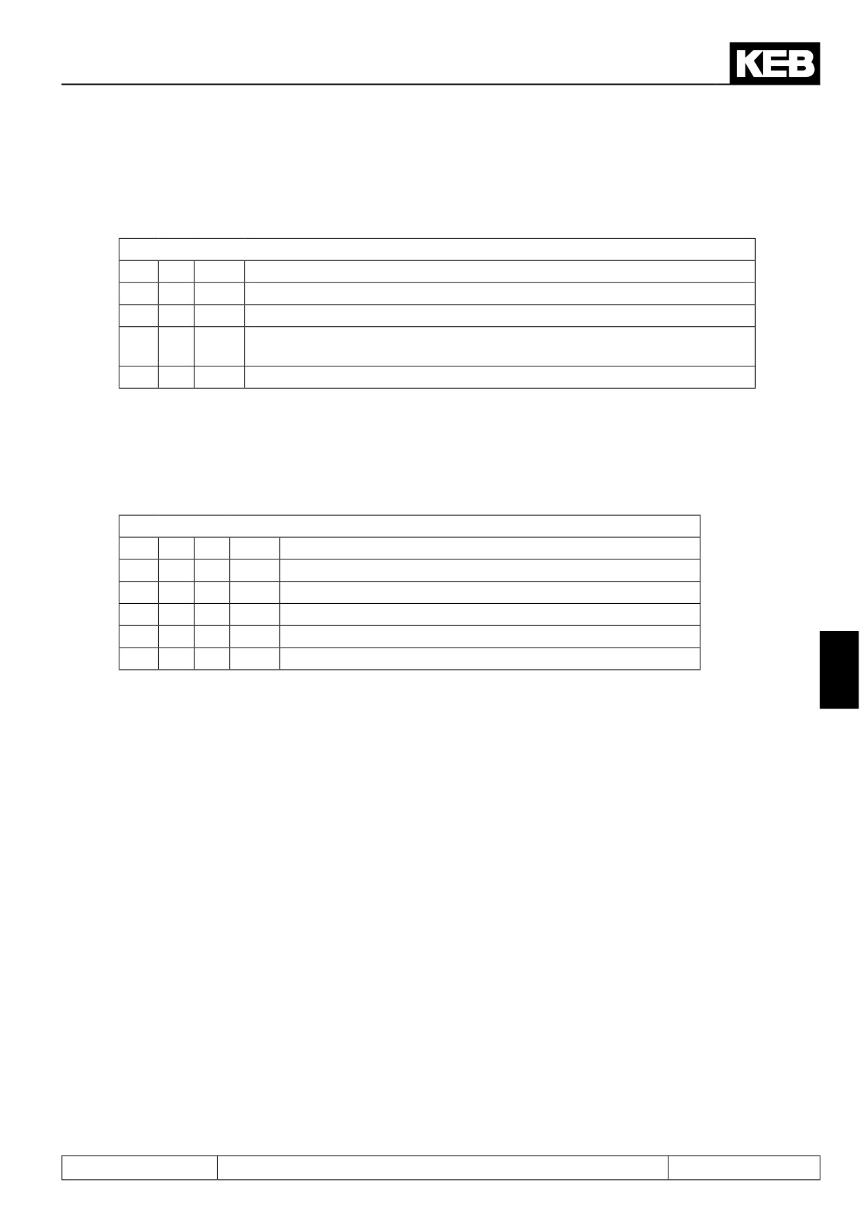
Bit 8 and 9 determine the set addressing:
Bit
8
9
Value
Function
0
0
0
direct set-addressing; the sets determined by Bit 0...7 are valid
0
1
256
current set; the current set is displayed / edited
512
indirect set addressing, the parameter set determined with the set pointer Fr.9
1
0
is displayed / edited
1
1
768
reserved
Display standardization
Bit 10...12 determine how the defined parameter value is displayed. Up to seven different user standardizations
(see further on in this chapter) can be determined with the parameters ud.18...21.
Bit
12
11
10
Value
Function
0
0
0
0
Use standard standardization of the parameter
0
0
1
1024
Display standardization of the parameters ud.18...21 from set 1
0
1
0
2048
Display standardization of the parameters ud.18...21 from set 2
1
1
1
7168
Display standardization of the parameters ud.18...21 from set 7
7
Page7.16 - 5
CP-Parameter Definition
7.16.3Example
As an example a user menu with the following features shall be programmed:
1.
Display of current actual frequency (ru.3) in the respective set
2.
Adjustment of a fixed frequency / fixed value (oP.21) in set 2
3.
Adjustment of a fixed frequency / fixed value (oP.21) in set 3
4.
Acceleration and deceleration time (oP.28/oP.30) for set 2 and 3
5.
Energy saving factor (uF.7) shall be displayed in set 0 with display standardization 4
1.)
ud.15 = 1
; CP.1
ud.16 = 0203h
; Parameter address for ru.3
ud.17 = 256
; Display in the active set
2.)
ud.15 = 2
; CP.2
ud.16
= 0315h
; Parameter address for oP.21
ud.17 = 4
; Setting in set 2
3.)
ud.15 = 3
; CP.3
ud.16 = 0315h
; Parameter address for oP.21
ud.17 = 8
; Setting in set 3
4.)
ud.15 = 4
; CP.4
ud.16 = 031Ch
; Parameter address for oP.28
ud.17 = 12
; Setting in set 2 and 3
ud.15 = 5
; CP.5
ud.16 = 031Eh
; Parameter address for oP.30
ud.17 = 12
; Setting in set 2 and 3
5.)
ud.15 = 6
; CP.6
ud.16 = 0507h
; Parameter address for uF.7
ud.17 = 4097
; Setting in set 0 and display standardization 4
6.)
ud.15 = 7
; CP.7
ud.16 = -1: off
; CP.7 not displayed
ud.17 = xxx
; ud.17 no function
Adjust all other parameter sets to „off“, so that no indication occurs.
The acceptance of the values takes place only after Power-On-Reset of the operator.
Page7.16 - 6
CP-Parameter Definition
7.16.4Display standardization
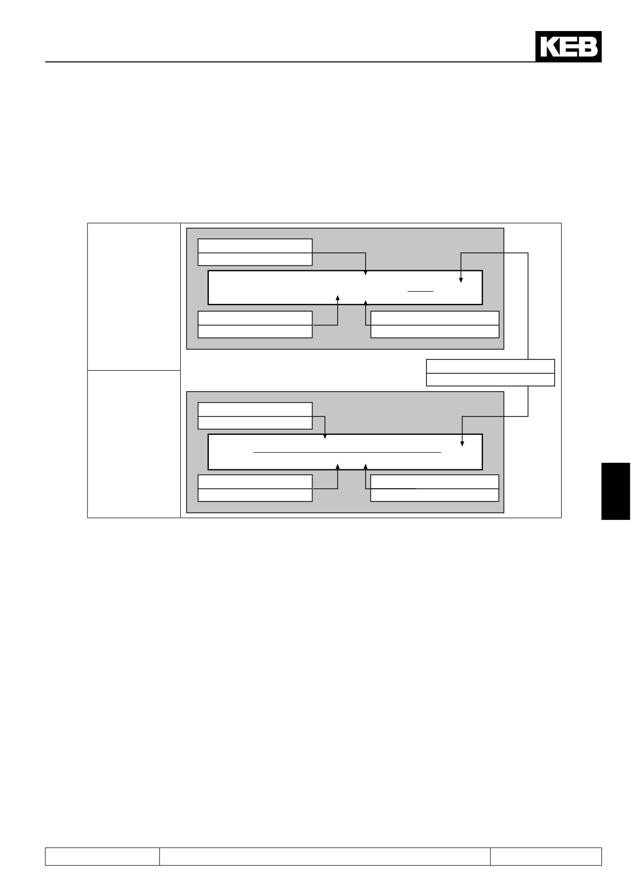
The KEB COMBIVERT gives the user the possibility to define his own standardizations (e.g. km/h or bottles/
min) in the CP-Mode. The parameters ud.18...20 are used for conversion, ud.21 for specifying the method of
calculation, the decimal places as well as the units indicated in KEB COMBIVIS.
7.16.4 Definition of own standardization
ud.19 numerator
± 32767
CP.xx = (selected parameter + ud.20) x ud.19 x
unit
Standard
ud.18
ud.20 offset
ud.18 denominator
± 32767
± 32767
ud.21 display flags
0...1791
ud.19 numerator
± 32767
Inverted
CP.xx =
ud.19
x unit
(selected parameter + ud.20) x ud.18
ud.20 offset
ud.18 denominator
7
± 32767
± 32767
The unstandardized value or the standardized value/resolution is always used for the „selected parameter“ !
ud.18 Divisor display norm
Adjusts the divisor in the range of ±32767 (default 1). The parameter is set-programmable.
ud.19 Multiplier display norm
Adjusts the multiplier in the range of ±32767 (default 1). The parameter is set-programmable.
ud.20 Offset display norm
Adjusts the offset in the range of ±32767 (default 0). The parameter is set-programmable.
Page7.16 - 7
CP-Parameter Definition
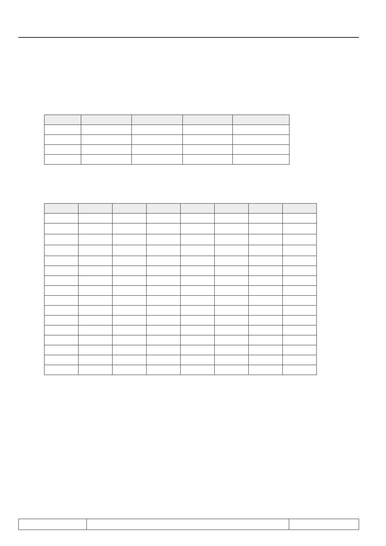
ud.21 Control display norm
With ud.21 the calculation mode, the decimal places as well as the units indicated in KEB COMBIVIS are adju-
sted. The parameter is bit-coded and set-programmable. It is adjustable in the range of 0...1791.
Bit 12...15
Bit 11...8
Bit 7...6
Bit 5...0
ud.21
-
-
-
see table 1
unit
-
-
see table 2
-
Calculation mode
-
see table 3
-
-
Representation
free
-
-
-
-
Table 1 Unit (Bit 0...5)
Value
unit
Value
unit
Value
unit
Value
unit
0
no
16
km/h
32
K
48
lbin
1
mm
17
rpm
33
mW
49
in/s
2
cm
18
Hz
34
W
50
ft/s
3
M
19
kHz
35
kW
51
ft/min
4
km
20
mV
36
inc
52
ft/s²
5
g
21
V
37
%
53
ft/s³
6
kg
22
kV
38
KWh
54
MPH
7
us
23
mW
39
mH
55
KP
8
ms
24
W
40
-
56
psi
9
s
25
kW
41
-
57
°F
10
h
26
VA
42
In
58
-
11
Nm
27
kVA
43
ft
59
-
12
kNm
28
mA
44
yd
60
-
13
m/s
29
A
45
oz
61
-
14
m/s2
30
kA
46
lb
62
-
15
m/s3
31
°C
47
lbft
63
-
Page7.16 - 8
CP-Parameter Definition
Table 2 Calculation mode (Bit 6...7)
Value
Function
0
ud.19
(selected parameter + ud.20) x
= CP.xx
———
ud.18
64
ud.19
= CP.xx
———————————————————
(selected parameter + ud.20) x ud.18
-
free
The unstandardized value is always used for the „selected parameter“!
unstandardized value = standardized value / resolution
Table 3 Representation (Bit 8...11)
Value
Representation
0
0 decimal places
256
1 decimal place
512
2 decimal places
768
3 decimal places
1024
4 decimal places
1280
variable decimal places
7
1536
Hexadecimal
-
free
Example
The actual frequency shall be displayed in CP.1 in rpm. Display standardization from set 4.
ud.15 = 1
; CP.1
ud.16 = 0203h
; Actual frequency ru.3
ud.17 = 4352
; Display in current set, display standardization from set 4
Set 4 ud.18 = 80
; Conversion from 1/80 Hz into rpm without pole pair number
Set 4 ud.19 = 60
Set 4 ud.20 = 0; no Offset
Set 4 ud.21 = 17
; Unit rpm; direct calculation mode;no decimal place
7.16.5Variable standardization
Page7.16 - 9