Goodrive350 Series High-performance Multi-function Inver ter. Operation manual - page 8
Chapter 9
•
The inverter returns an exception response.
Possible causes of no response include the following:
•
The serial port is set incorrectly. For example, the converter uses the serial port COM1, but
COM2 is selected for the communication.
•
The settings of the baud rates, data bits, end bits, and check bits are inconsistent with those set
on the inverter.
•
The positive pole (+) and negative pole (-) of the RS485 bus are connected reversely.
•
The resistor connected to 485 terminals on the terminal block of the inverter is set incorrectly.
-275-
Appendix A
Appendix A Extension cards
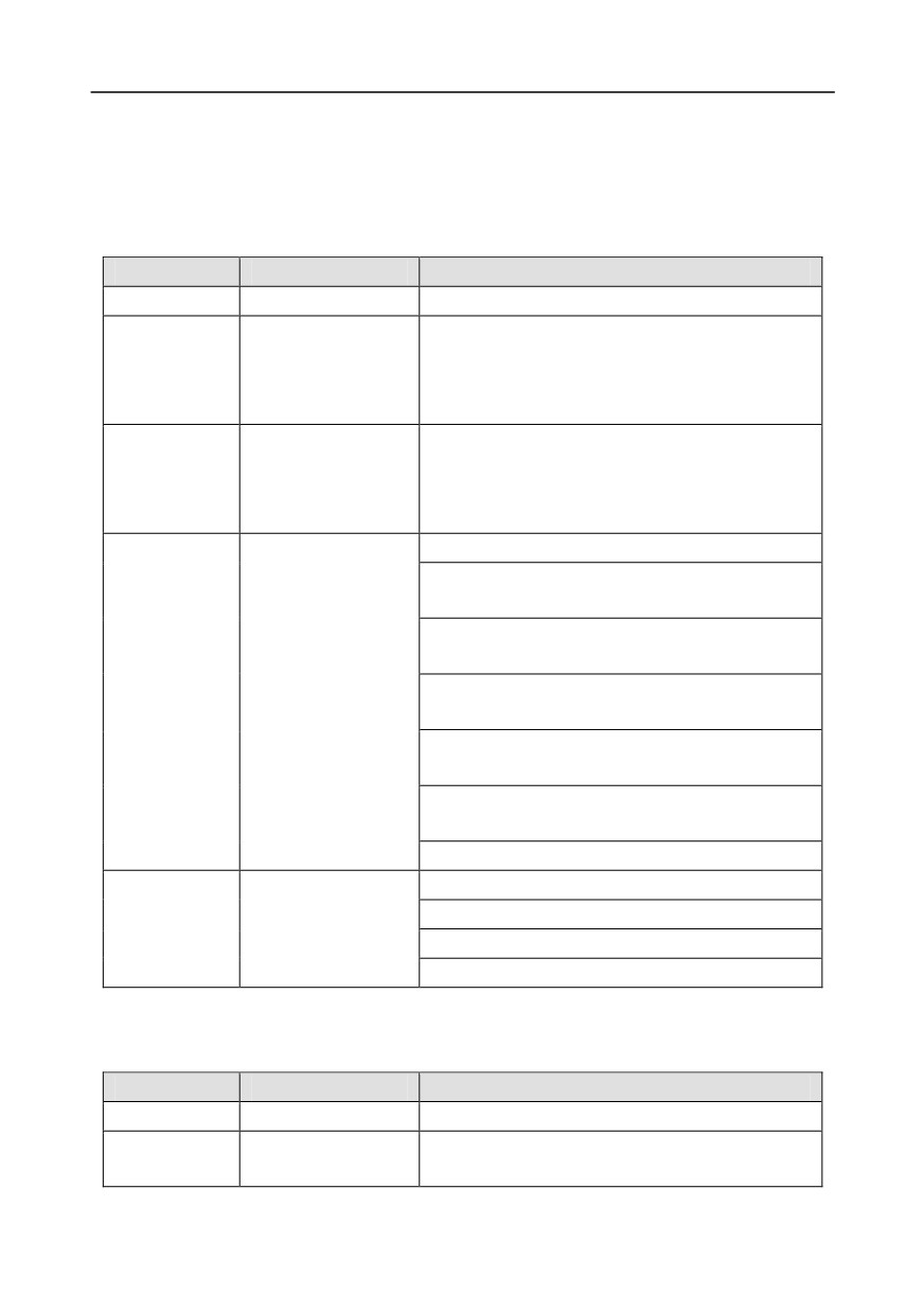
A.1 Model definition
EC - PG 5 01 - 05
①
② ③ ④
⑤
Field identifier
Field description
Naming example
①
Product category
EC: Extension card
PG: PG card
PC: PLC programmable card
②
Card category
IO: IO extension card
TX: Communication extension card
Indicates the generation of a technical version by
using odd numbers, for example, 1, 3, and 5
③
Technical version
indicate the 1st, 2nd, and 3rd generations of the
technical version.
01: Incremental PG card + frequency-divide output
02: Sine/Cosine PG card + pulse direction setting +
frequency-divide output
03: UVW PG interface + pulse direction setting +
frequency-divide output
04: Resolver PG interface + pulse direction setting +
④
Distinguishing code
frequency-divide output
05: Incremental PG card + pulse direction setting +
frequency-divide output
06: Absolute PG interface + pulse direction setting +
frequency-divide output
07: Reserved 2
00: Passive
05: 5V
⑤
Working power
12: 12-15 V
24: 24 V
EC- PC 5 01 - 00
①
② ③ ④
⑤
Field identifier
Field description
Naming example
①
Product category
EC: Extension card
IO: IO extension card
②
Card category
TX: Communication extension card
-276-
Appendix A
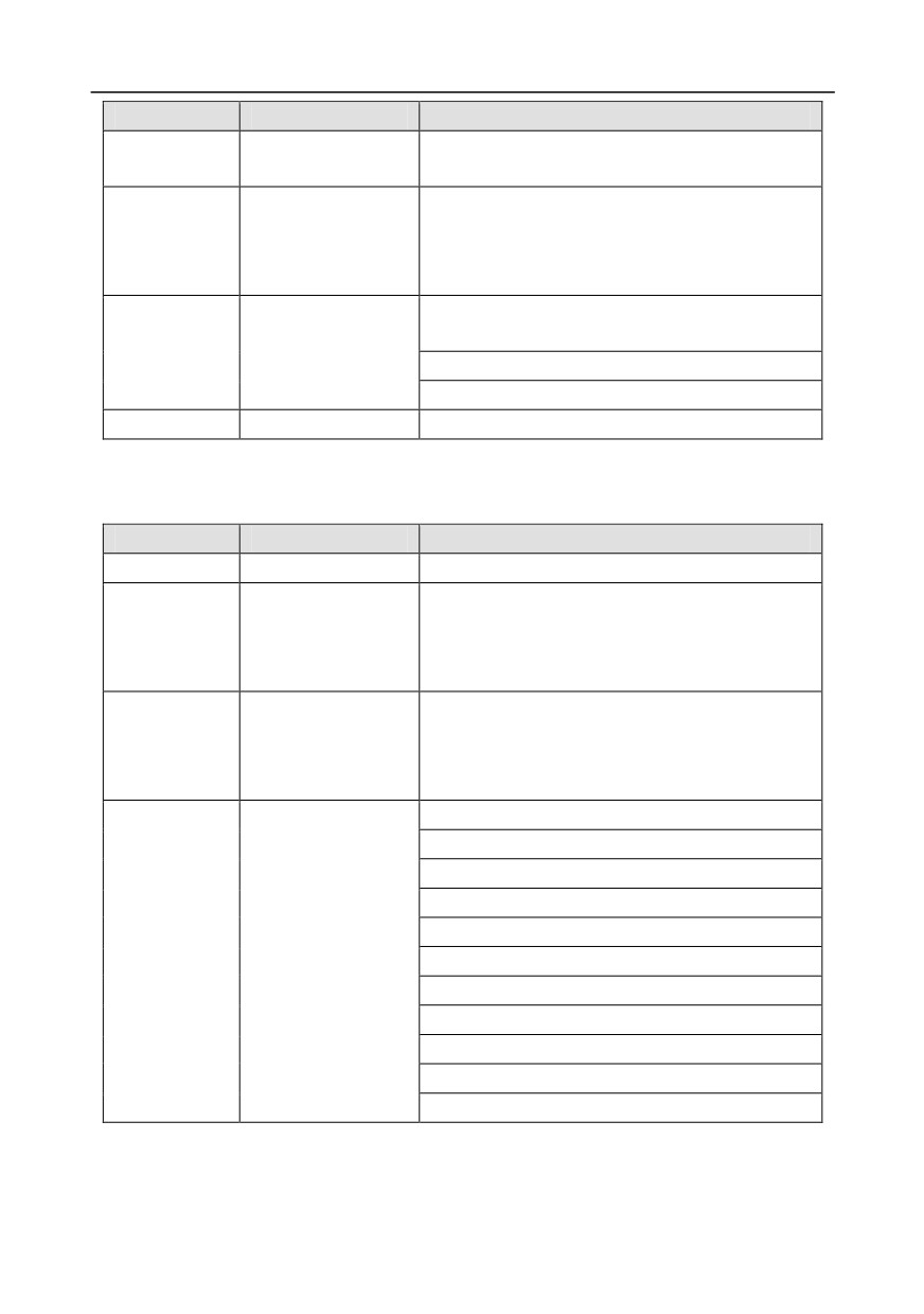
Field identifier
Field description
Naming example
PG: PG card
PC: PLC programmable card
Indicates the generation of a technical version by
using odd numbers, for example,
1,
3, and
5
③
Technical version
indicate the
1st,
2nd, and
3rd generations of the
technical version.
01: 10 points, 6 inputs and 4 outputs (2 transistor
outputs + 2 relay outputs)
④
Distinguishing code
02: 14 points, 8 inputs and 6 outputs (relay outputs)
03: Reserved
⑤
Special requirement
Reserved
EC - TX 5 01
①
② ③ ④
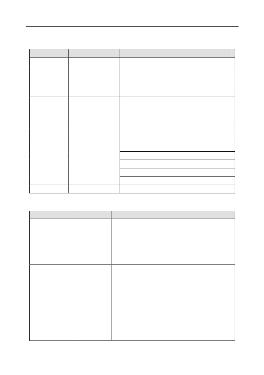
Field identifier
Field description
Naming example
①
Product category
EC: Extension card
TX: Communication extension card
PG: PG card
②
Card category
PC: PLC programmable card
IO: IO extension card
Indicates the generation of a technical version by
using odd numbers, for example, 1, 3, and 5
③
Technical version
indicate the 1st, 2nd, and 3rd generations of the
technical version.
01: Bluetooth communication card
02: WIFI communication card
03: PROFIBUS communication card
04: Ethernet communication card
05: Canopen communication card
④
Distinguishing code
06: DeviceNet communication card
07: BACnet communication card
08: EtherCat communication card
09: PROFINET communication card
10: 485 communication card
11: CAN master/slave control communication card
-277-
Appendix A
EC- IO 5 01 - 00
①
② ③ ④
⑤
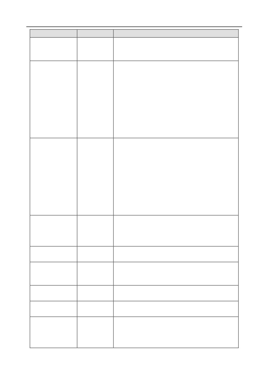
Field identifier
Field description
Naming example
①
Product category
EC: Extension card
IO: IO extension card
TX: Communication extension card
②
Card category
PG: PG card
PC: PLC programmable card
Indicates the generation of a technical version by
using odd numbers, for example, 1, 3, and 5
③
Technical version
indicate the 1st, 2nd, and 3rd generations of the
technical version.
01: Multiple-function I/O extension card (4 digital
inputs, 1 digital output, 1 analog input, 1 analog
output, and 2 relay outputs)
④
Distinguishing code
02: Digital I/O card
03: Analog I/O card
04: Reserved 1
05: Reserved 2
⑤
Special requirement
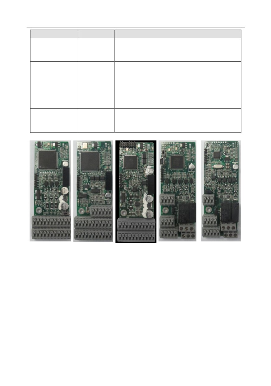
The following table describes extension cards that Goodrive350 series inverters support. The
extension cards are optional and need to be purchased separately
Name
Model
Specification
4 digital inputs
1 digital output
1 analog input
IO extension card
EC-IO501-00
1 analog output
2 relay outputs: 1 double-contact output, and 1
single-contact output
Adopting the global mainstream development
environment CODESYS, supporting multiple types of
programming languages, such as the instruction
language, structural text, function block diagram,
Programmable
ladder diagram, continuous function chart, and
EC-PC501-00
extension card
sequential function chart
Supporting breakpoint commissioning
Providing user program storage space of 128 kB,
and data storage space of 64 kB
6 digital inputs
-278-
Appendix A
Name
Model
Specification
2 digital outputs
2 relay outputs: 1 double-contact output, and 1
single-contact output
Supporting Bluetooth 4.0
With INVT's mobile phone APP, you can set the
parameters and monitor the states of the inverter
through Bluetooth
Bluetooth
EC-TX501-1
The maximum communication distance in open
communication card
EC-TX501-2
environments is 30 m.
EC-TX501-1 is equipped with a built-in antenna and
applicable to molded case machines.
EC-TX501-2 is configured with an external sucker
antenna and applicable to sheetmetal machines.
Meeting IEEE802.11b/g/n
With INVT's mobile phone APP, you can monitor the
inverter locally or remotely through WIFI
communication
WIFI
EC-TX502-1
The maximum communication distance in open
communication card
EC-TX502-2
environments is 30 m.
EC-TX501-1 is equipped with a built-in antenna and
applicable to molded case machines.
EC-TX501-2 is configured with an external sucker
antenna and applicable to sheetmetal machines.
Supporting Ethernet communication with INVT's
Ethernet
internal protocol
EC-TX504
communication card
Can be used in combination with INVT's upper
computer monitoring software INVT Studio
CANopen
Based on the CAN2.0A physical layer
EC-TX505
communication card
Supporting the CANopen protocol
CAN master/slave
Based on the CAN2.0B physical layer
control
EC-TX511
Adopting INVT's master-slave control proprietary
communication card
protocol
PROFIBUS-DP
Supporting the PROFIBUS-DP protocol
EC-TX503
communication card
PROFINET
Supporting the PROFINET protocol
EC-TX509
communication card
Applicable to OC encoders of 5 V or 12 V
Multi-function
Applicable to push-pull encoders of 5 V or 12 V
EC-PG505-12
incremental PG card
Applicable to differential encoders of 5 V
Supporting the orthogonal input of A, B, and Z
-279-
Appendix A
Name
Model
Specification
Supporting the frequency-divided output of A, B, and
Z
Supporting pulse string setting
Applicable to differential encoders of 5 V
Supporting the orthogonal input of A, B, and Z
UVW incremental
Supporting pulse input of phase U, V, and W
EC-PG503-05
PG card
Supporting the frequency-divided output of A, B, and
Z
Supporting the input of pulse string reference
Applicable to resolver encoders
Resolver PG card
EC-PG504-00
Supporting frequency-divided output of
resolver-simulated A, B, Z
Multi-function
UVW
Resolver PG
Programmable
IO extension card
incremental PG
incremental PG
card
extension card
EC-IO501-00
card
card
EC-PG504-00
EC-PC501-00
EC-PG505-12
EC-PG503-05
-280-
Appendix A
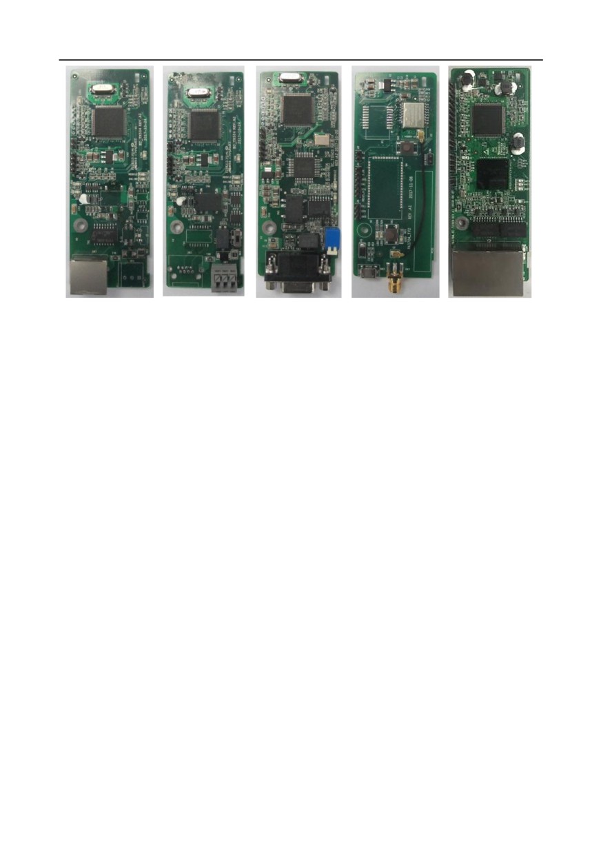
Ethernet
CANopen
PROFIBUS-DP
Bluetooth/WIFI
PROFINET
communication
communication
communication
communication
communication
card
card
card
card
card
EC-TX504
EC-TX505/511
EC-TX503
EC-TX501-1/50
EC-TX509
2
A.2 Dimensions and installation
All extension cards are of the same dimensions (108 mm × 39 mm) and can be installed in the same
way.
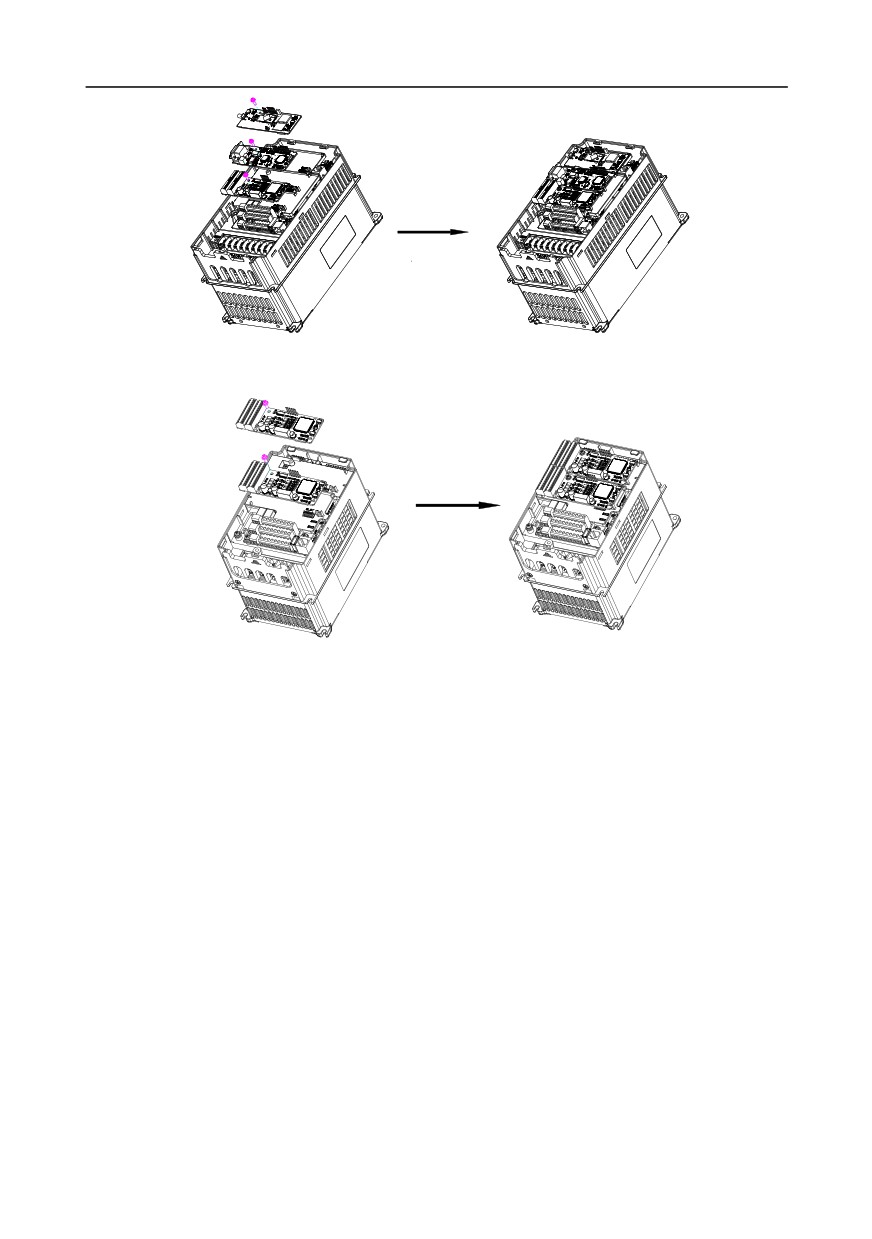
Following the following operation principles when installing or removing an extension card:
1. Ensure that no power is applied before installing the extension card.
2. The extension card can be installed in any one of the SLOT1, SLOT2, and SLOT3 card slots.
3. Inverters of 5.5 kW or lower can be configured with two extension cards at the same time, and
those of 7.5 kW or higher can be configured with three extension cards.
4. If interference occurs on the external wires after extension cards are installed, change their
installation card slots flexibly to facilitate the wiring. For example, the connector of the connection
cable of the DP card is large, so it is recommended to be installed in the SLOT1 card slot.
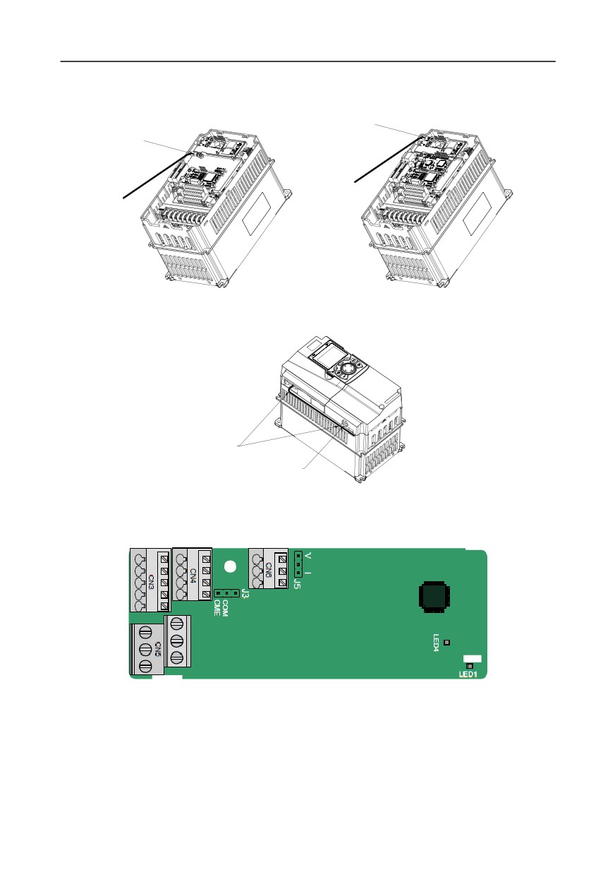
Fig A.1 shows the installation diagram and an inverter with extension cards installed.
-281-
Appendix A
EC 1
EC 1
EC2
EC
2
EC3
EC3
EC installation diagram
Diagram of ECs installed
Fig A.1 Inverter of 7.5 kW or higher with extension cards installed
EC 1
EC 1
EC 2
EC 2
ECs installing
ECs installed
Fig A.2 Inverter of 5.5 kW or lower with extension cards installed
-282-
Appendix A
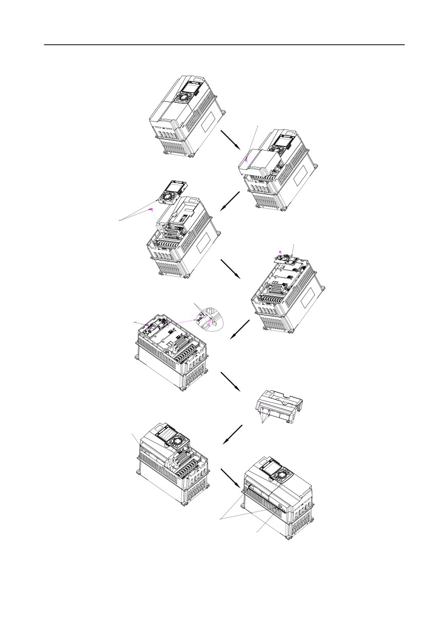
Extension card installation process:
STEP 1
Unscrew the screws and remove th e lower cover
STEP 2
STEP 3
Unscrew the screws,
take out the keypad,
and remove the upper cover
Insert the EC
STEP 4
Align the EC positioning holes
and positioning studs to fix the EC
STEP 5
Tighten the screws
Scale 4:1
STEP 6
STEP 7
Diagram of outlet box cut
Cut the corresponding outlet box
STEP 8
Diagram of installation wiring
Wire binding position
Fig A.3 Extension card installation process diagram
-283-
Appendix A
A.3 Wiring
1.
Ground a shielded cable as follows:
Grounding position of the
shielded cable
Grounding position of
the shielded cable
Fig A.4 Extension card grounding diagram
2.
Wire an extension card as follows:
EC wiring
EC wire binding position
Fig A.5 Extension card wiring
A.4 IO extension card function description
A.4.1 IO extension card--EC-IO501-00
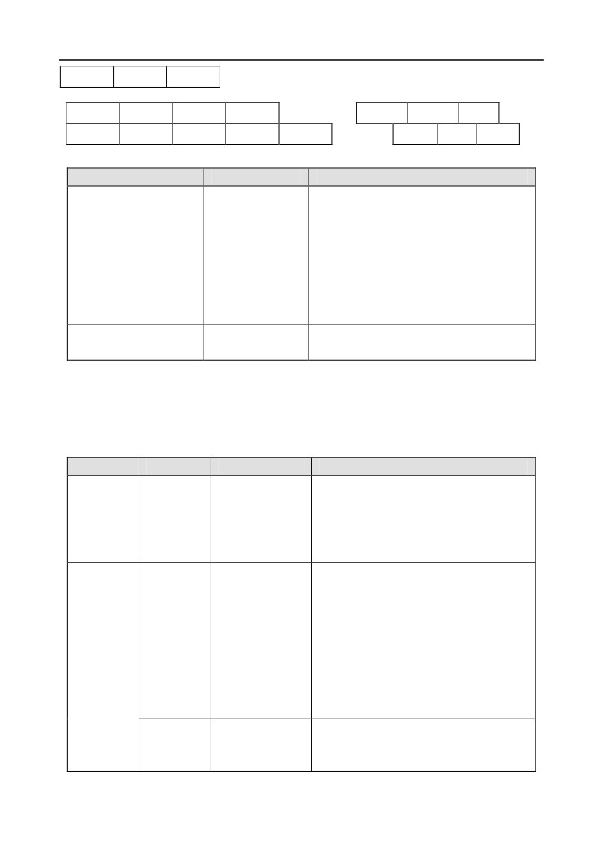
The terminals are arranged as follows:
CME and COM are shorted through J3 before delivery, and J5 is the jumper for selecting the output
type (voltage or current) of AO2.
-284-
Appendix A
AI3
AO2
GND
COM
CME
Y2
S5
RO3A
RO3B
RO3C
PW
+24V
S6
S7
S8
RO4A
RO4C
Indicator definition
Indicator No.
Definition
Function
This indicator is on when the extension card
is establishing a connection with the control
board; it blinks periodically after the
extension card is properly connected to the
LED1
State indicator
control board (the period is 1s, on for 0.5s,
and off for the other 0.5s); and it is off when
the extension card is disconnected from the
control board.
This indicator is on after the IO extension
LED4
Power indicator
card is powered on by the control board.
The EC-IO501-00 extension card can be used in scenarios where the I/O interfaces of a Goodrive350
inverter cannot meet the application requirements. It can provide 4 digital inputs, 1 digital output, 1
analog input, 1 analog output, and two relay outputs. It is user-friendly, providing relay outputs
through European-type screw terminals and other inputs and outputs through spring terminals.
EC-IO501-00 terminal function description
Category
Label
Name
Function description
The working power of digital input is
provided by an external power supply.
External power
Power
PW
Voltage range: 12-24 V
supply
The terminals PW and +24V are shorted
before delivery.
1. Input range: 0-10 V, 0-20 mA
2. Input impedance: 20 kΩ for voltage input;
250 Ω for current input
3. Set it to be voltage or current input
AI3—GND
Analog input 1
through the corresponding function code.
Analog
4. Resolution: When 10 V corresponds to
input/output
50 Hz, the minimum resolution is 5 mV.
5. Deviation:±0.5%; input of 5 V or 10 mA or
higher at the temperature of 25°C
1. Output range: 0-10 V, 0-20 mA
AO2—GND
Analog output 1
2. Whether it is voltage or current output is
determined by J5.
-285-
Appendix A
Category
Label
Name
Function description
3. Deviation ±0.5%; input of 5 V or 10 mA or
higher at the temperature of 25°C
S5—COM
Digital input 1
1. Internal impedance: 3.3 kΩ
S6—COM
Digital input 2
2. Power input range: 12-30 V
S7—COM
Digital input 3
3. Bidirectional input terminal
Digital
S8—COM
Digital input 4
4. Max. input frequency: 1 kHz
input/output
1. Switch capacity: 200 mA/30 V
2. Output frequency range: 0-1 kHz
Y2—CME
Digital output
3. The terminals CME and COM are
shorted through J3 before delivery.
NO contact of
R03A
relay 3
NC contact of
R03B
relay 3
1. Contact capacity: 3A/AC 250 V, 1 A/DC
Relay
Common contact
30 V
R03C
output
of relay 3
2. Do not use them as high-frequency
NO contact of
digital outputs.
R04A
relay 4
Common contact
R04C
of relay 4
A.5 PG extension card function description
A.5.1 Multi-function incremental PG card--EC-PG505-12
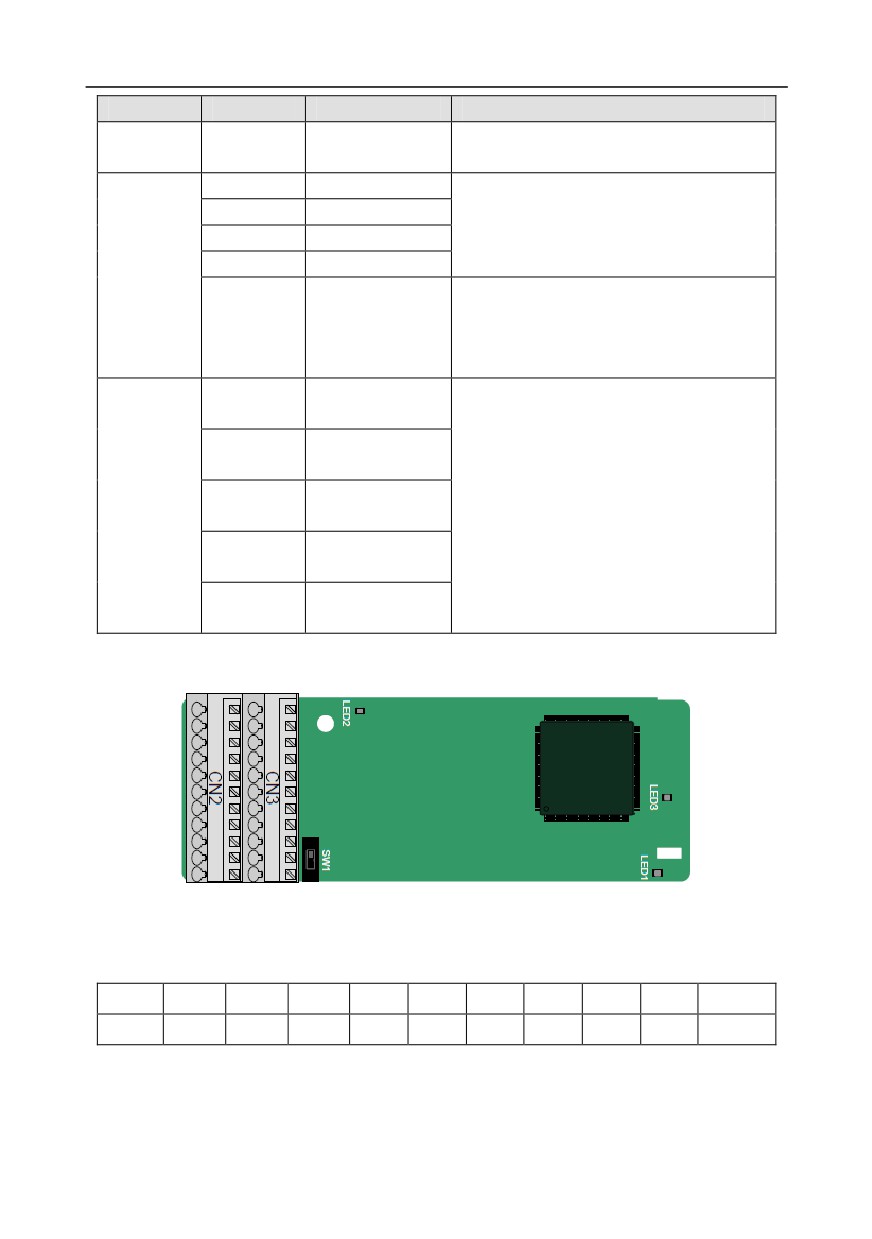
The terminals are arranged as follows:
The dual in-line package (DIP) switch SW1 is used to set the voltage class (5 V or 12 V) of the power
supply of the encoder. The DIP switch can be operated with an auxiliary tool.
PE
AO+
BO+
ZO+
A1+
B1+
Z1+
A2+
B2+
Z2+
PWR
GND
AO-
BO-
ZO-
A1-
B1-
Z1-
A2-
B2-
Z2-
PGND
Indicator definition
-286-
Appendix A
Indicator No.
Definition
Function
This indicator is on when the extension card is
establishing a connection with the control board; it
blinks periodically after the extension card is
LED1
State indicator
properly connected to the control board
(the
period is 1s, on for 0.5s, and off for the other 0.5s);
and it is off when the extension card is
disconnected from the control board.
This indicator is off when A1 and B1 of the
Disconnection
LED2
encoder is disconnected; and it is on when the
indicator
pulses are normal.
This indicator is on after the control board feeds
LED3
Power indicator
power to the PG card.
The EC-PG505-12 extension card can be used in combination with multiple types of incremental
encoders through different modes of wiring. It is user-friendly, adopting spring terminals.
EC-PG505-12 terminal function description
Label
Name
Function description
PWR
Voltage: 5 V/12 V ±5%
Max. output: 150 mA
Encoder power
Select the voltage class through the DIP switch
PGND
SW1 based on the voltage class of the used
encoder.
A1+
A1-
1. Supporting push-pull interfaces of 5 V/12 V
B1+
2. Supporting open collector interfaces of 5 V/12 V
Encoder interface
B1-
3. Supporting differential interfaces of 5 V
Z1+
4. Response frequency: 200 kHz
Z1-
A2+
A2-
1. Supporting the same signal types as the
B2+
Pulse setting
encoder signal types
B2-
2. Response frequency: 200 kHz
Z2+
Z2-
AO+
AO-
1. Differential output of 5 V
BO+
Frequency-divided
2. Supporting frequency division of 1-255, which
BO-
output
can be set through P20.16 or P24.16
ZO+
ZO-
-287-
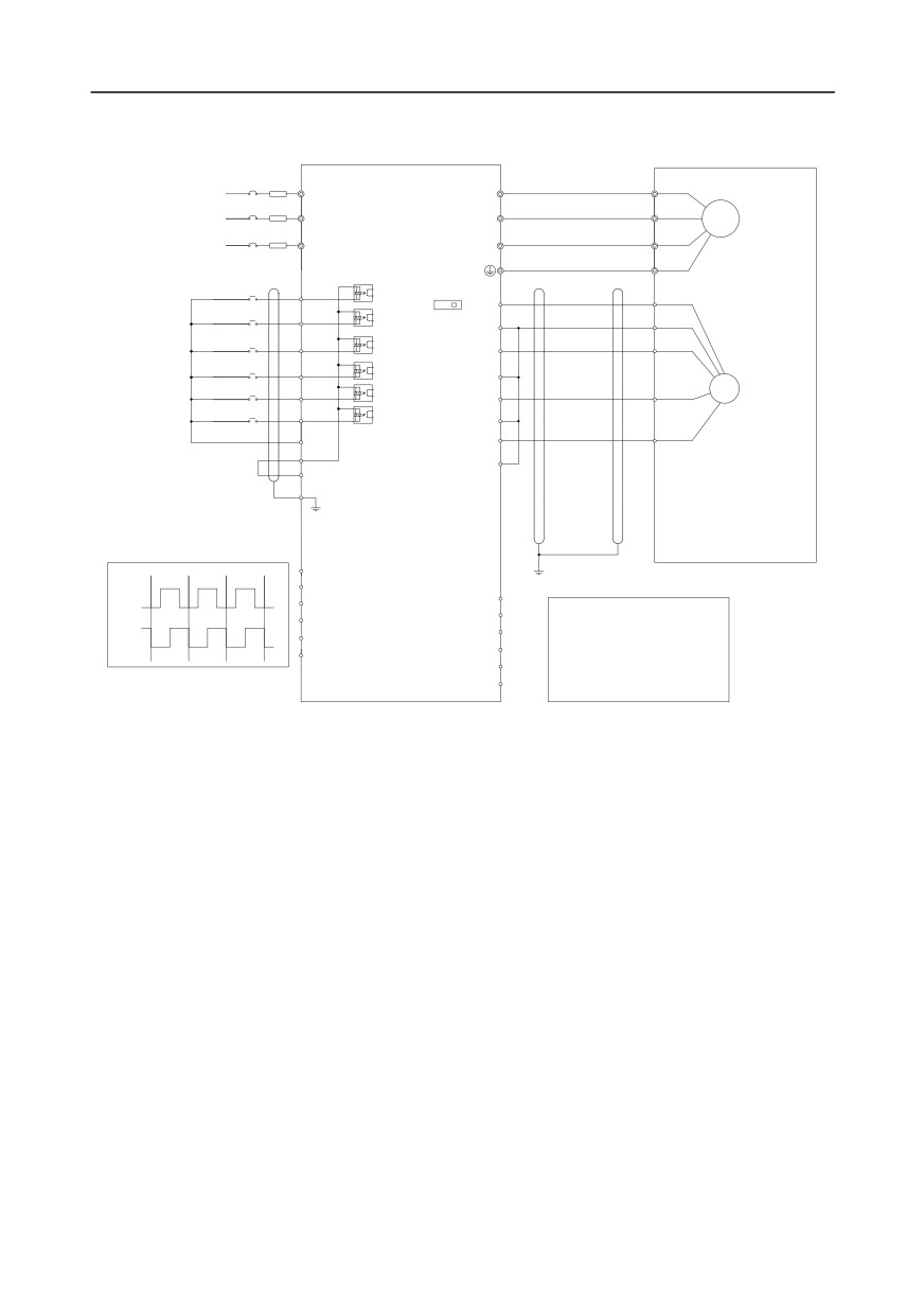
Appendix A
The following figure shows the external wiring of the extension card used in combination with an open
collector encoder. A pull-up resistor is configured inside the PG card.
U
R
U
S
V
V
M3~
T
W
W
Forward
S1
running
SW1
Forward
PWR
S2
5V
12V
jogging
PGND
S3
Fault reset
A
A1+
S4
A1-
HDIA
B
PG
B1+
HDIB
B1-
COM
Z1+
Z
PW
Z1-
+24V
PE
AO+
AO-
pulse A
BO+
A2+
A2-
BO-
CNC
B2+
pulse B
ZO+
PLC
ZO-
B2-
Upper computer
Z2+
Z2-
-288-
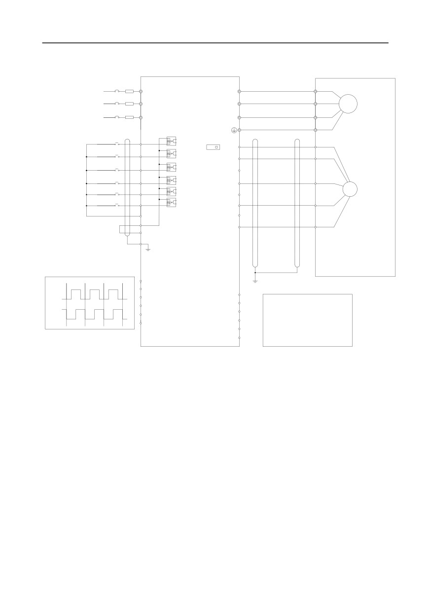
Appendix A
The following figure shows the external wiring of the extension card used in combination with a
push-pull encoder.
R
U
U
S
V
V
M3~
W
T
W
Forward
S1
running
SW1
Forward
PWR
S2
5V
12V
jogging
PGND
S3
Fault reset
A1+
S4
A
A1-
HDIA
PG
B1+
HDIB
B
B1-
COM
Z1+
PW
Z
Z1-
+24V
PE
AO+
AO-
pulse A
BO+
A2+
A2-
BO-
CNC
B2+
pulse B
ZO+
PLC
B2-
ZO-
Upper computer
Z2+
Z2-
-289-
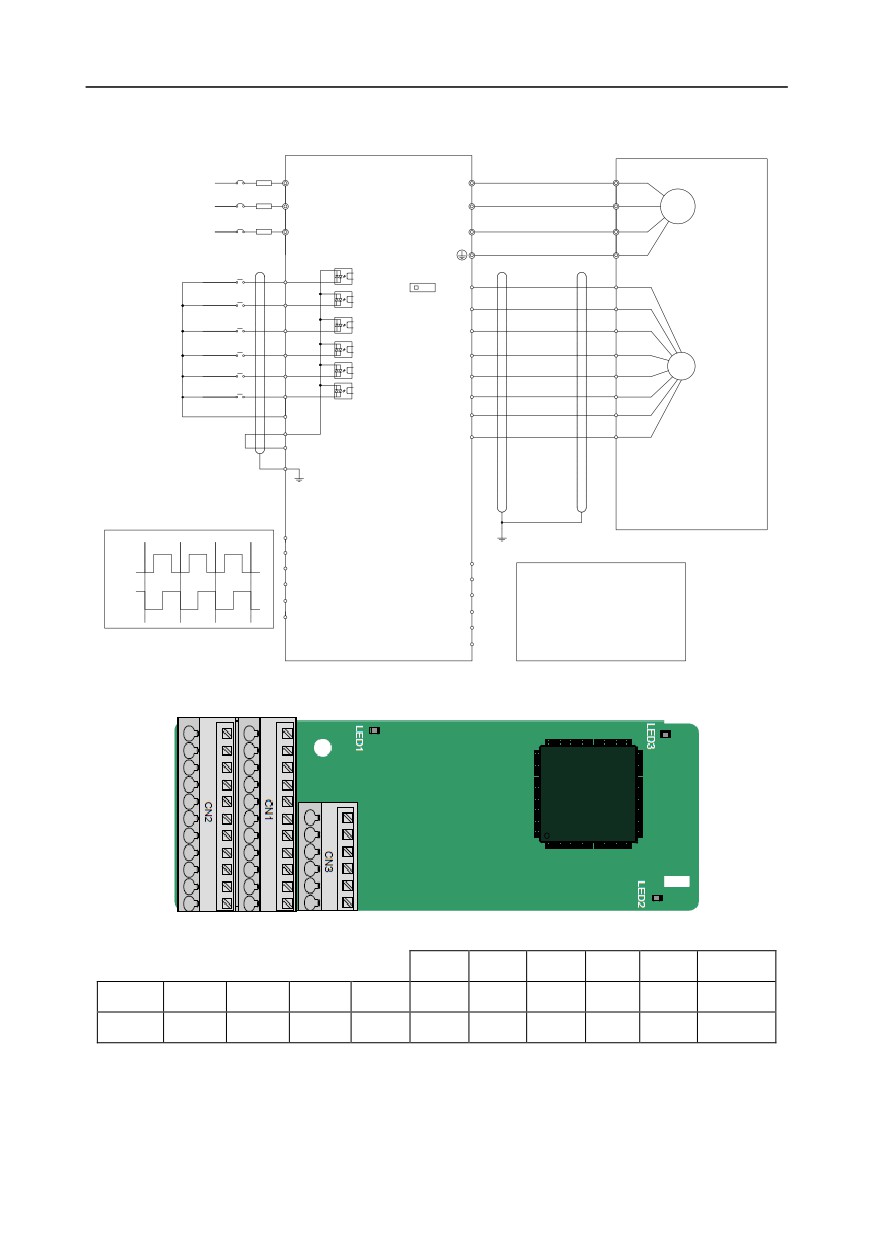
Appendix A
The following figure shows the external wiring of the extension card used in combination with a
differential encoder.
R
U
U
S
V
V
M3~
T
W
W
Forward
S1
running
SW1
Forward
PWR
S2
5V
12V
jogging
PGND
S3
Fault reset
A1+
S4
A1-
HDIA
PG
B1+
HDIB
B1-
COM
Z1+
PW
Z1-
+24V
PE
AO+
AO-
pulse A
A2+
BO+
BO-
A2-
CNC
pulse B
ZO+
B2+
PLC
ZO-
B2-
Upper computer
Z2+
Z2-
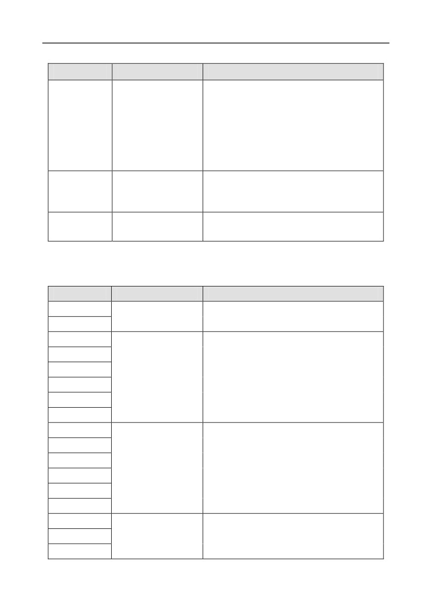
A.5.2 UVW incremental PG card--EC-PG503-05
The terminals are arranged as follows:
A2+
A2-
B2+
B2-
Z2+
Z2-
PE
AO+
BO+
ZO+
A1+
B1+
Z1+
U+
V+
W+
PWR
GND
AO-
BO-
ZO-
A1-
B1-
Z1-
U-
V-
W-
PGND
-290-
Appendix A
Indicator definition
Indicator No.
Definition
Function
This indicator is on when the extension card is
establishing a connection with the control board; it
blinks periodically after the extension card is
LED1
State indicator
properly connected to the control board
(the
period is 1s, on for 0.5s, and off for the other
0.5s); and it is off when the extension card is
disconnected from the control board.
This indicator is off when A1 and B1 of the
LED2
Disconnection indicator
encoder is disconnected; and it is on when the
pulses are normal.
This indicator is on after the control board feeds
LED3
Power indicator
power to the PG card.
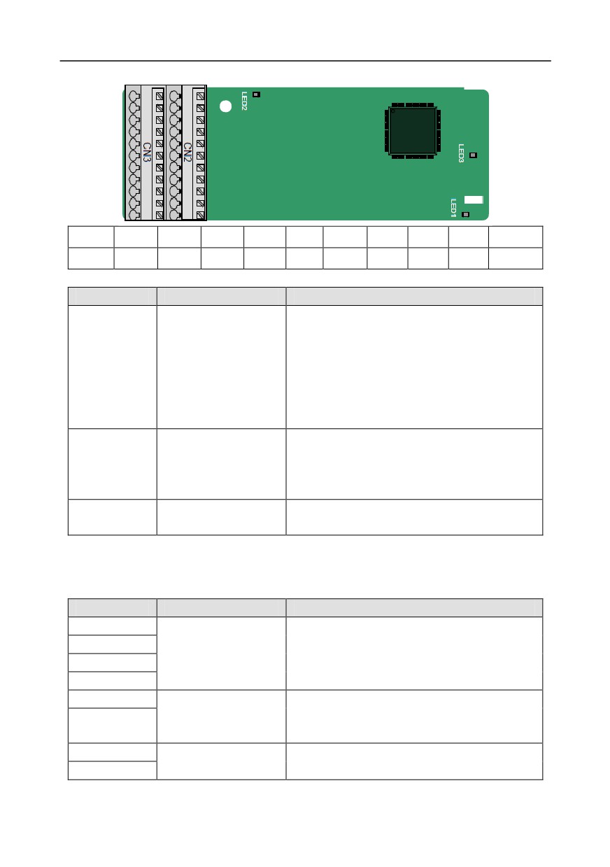
The EC-PG503-05 extension card supports the input of absolute position signals and integrates the
advantages of absolute and incremental encoders. It is user-friendly, adopting spring terminals.
EC-PG503-05 terminal function description
Label
Name
Function description
PWR
Voltage: 5 V±5%
Encoder power
PGND
Max. current: 200 mA
A1+
A1-
B1+
1. Differential incremental PG interface of 5 V
Encoder interface
B1-
2. Response frequency: 400 kHz
Z1+
Z1-
A2+
A2-
B2+
1. Differential input of 5 V
Pulse setting
B2-
2. Response frequency: 200 kHz
Z2+
Z2-
AO+
1. Differential output of 5 V
Frequency-divided
AO-
2. Supporting frequency division of 1-255, which
output
can be set through P20.16 or P24.16
BO+
-291-
Appendix A
Label
Name
Function description
BO-
ZO+
ZO-
U+
U-
1. Absolute position (UVW information) of the
V+
UVW encoder interface
hybrid encoder, differential input of 5 V
V-
2. Response frequency: 40 kHz
W+
W-
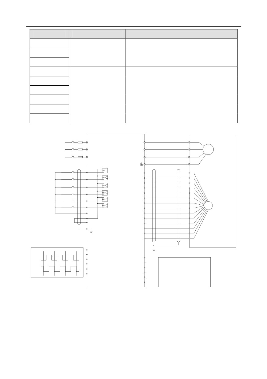
The following figure shows the external wiring of the EC-PG503-05 extension card.
R
U
U
V
S
V
M3~
T
W
W
Forward
running
S1
Forward
PWR
jogging
S2
PGND
S3
A1+
Fault reset
A1-
S4
B1+
HDIA
B1-
Z1+
HDIB
PG
Z1-
COM
U+
PW
U-
+24V
V+
PE
V-
W+
W-
AO+
AO-
pulse A
BO+
A2+
A2-
BO-
CNC
B2+
pulse B
ZO+
PLC
B2-
ZO-
Upper computer
Z2+
Z2-
-292-
Appendix A
A.5.3 Resolver PG card--EC-PG504-00
PE
AO+
BO+
ZO+
EX+
SI+
CO+
A2+
B2+
Z2+
PWR
GND
AO-
BO-
ZO-
EX-
SI-
CO-
A2-
B2-
Z2-
PGND
Indicator definition
Indicator No.
Definition
Function
This indicator is on when the extension card is
establishing a connection with the control board; it
blinks periodically after the extension card is
LED1
State indicator
properly connected to the control board
(the
period is 1s, on for 0.5s, and off for the other
0.5s); and it is off when the extension card is
disconnected from the control board.
This indicator is off when the encoder is
disconnected; it is on when the encoder signals
LED2
Disconnection indicator
are normal; and it blinks when the encoder signals
are not stable.
This indicator is on after the control board feeds
LED3
Power indicator
power to the PG card.
The EC-PG504-00 extension card can be used in combination with a resolver of excitation voltage 7
Vrms. It is user-friendly, adopting spring terminals.
EC-PG504-00 terminal function description
Label
Name
Function description
SI+
SI-
Encoder signal input
Recommended resolver transformation ratio: 0.5
CO+
CO-
EX+
1. Factory setting of excitation: 10 kHz
Encoder excitation
2. Supporting resolvers with an excitation voltage
EX-
signal
of 7 Vrms
A2+
1. Differential input of 5 V
Pulse setting
A2-
2. Response frequency: 200 kHz
-293-
Appendix A
Label
Name
Function description
B2+
B2-
Z2+
Z2-
AO+
1. Differential output of 5 V
AO-
2. Frequency-divided output of resolver simulated
BO+
A1, B1, and Z1, which is equal to an incremental
Frequency-divided
BO-
PG card of 1024 pps.
output
ZO+
3. Supporting frequency division of 1-255, which
can be set through P20.16 or P24.16
ZO-
4. Max. output frequency: 200 kHz
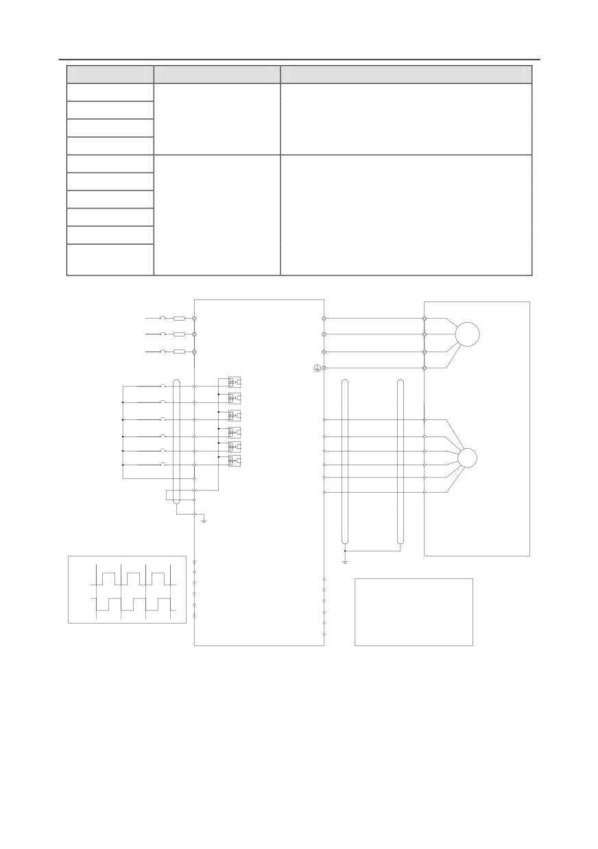
The following figure shows the external wiring of the EC-PG504-00 extension card.
R
U
U
S
V
V
M3~
W
T
W
Forward
running
S1
Forward
S2
jogging
S3
Fault reset
SI+
S4
SI-
HDIA
CO+
HDIB
PG
CO-
COM
EX+
PW
EX-
+24V
PE
AO+
AO-
pulse A
BO+
A2+
A2-
BO-
CNC
B2+
pulse B
ZO+
PLC
ZO-
B2-
Upper computer
Z2+
Z2-
-294-
Appendix A
A.6 Communication card function description
A.6.1 Bluetooth communication card--EC-TX501 and WIFI communication card--EC- TX502
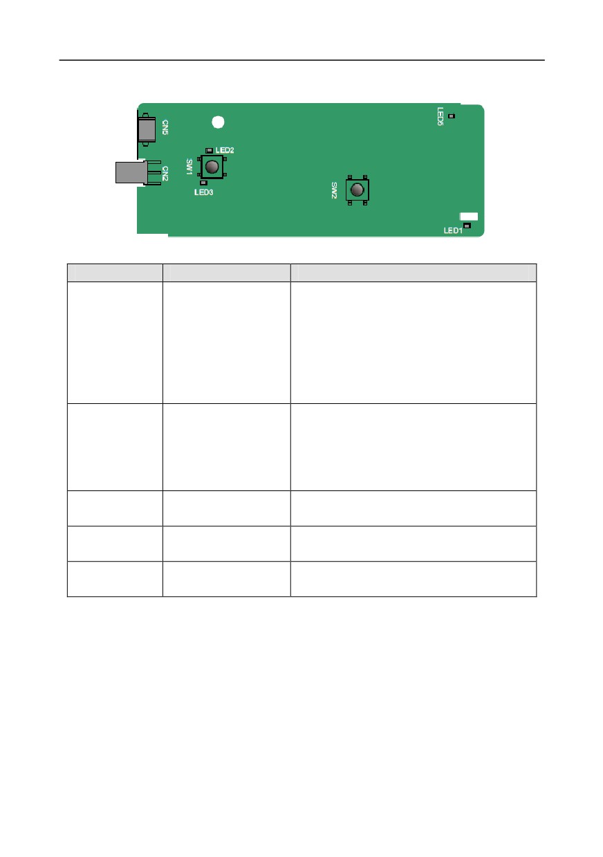
Definitions of indicators and function buttons:
Indicator No.
Definition
Function
LED1 is on when the extension card is
establishing a connection with the control board;
LED1 blinks periodically after the extension card
Bluetooth/WIFI state
LED1/LED3
is properly connected to the control board (the
indicator
period is 1s, on for 0.5s, and off for the other
0.5s); and LED1 is off when the extension card
is disconnected from the control board.
This indicator is on when Bluetooth
Bluetooth
communication is online and data exchange can
LED2
communication state
be performed.
indicator
It is off when Bluetooth communication is not in
the online state.
This indicator is on after the control board feeds
LED5
Power indicator
power to the Bluetooth card.
WIFI factory reset
It is restored to default values and returned to
SW1
button
the local monitoring mode.
WIFI hardware reset
SW2
It is used to reboot the extension card.
button
The wireless communication card is especially useful for scenarios where you cannot directly use the
keypad to operate the inverter due to the restriction of the installation space. With a mobile phone
APP, you can operate the inverter in a maximum distance of 30 m. You can choose a PCB antenna or
an external sucker antenna. If the inverter is located in an open space and is a molded case machine,
you can use a built-in PCB antenna; and if it is a sheetmetal machine and located in a metal cabinet,
you need to use an external sucker antenna.
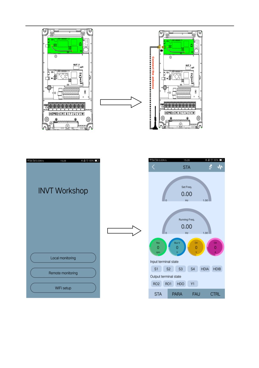
When installing a sucker antenna, install a wireless communication card on the inverter first, and then
lead the SMA connector of the sucker antenna into the inverter and screw it to CN2, as shown in the
following figure. Place the antenna base on the chassis and expose the upper part. Try to keep it
unblocked.
-295-
Appendix A
The wireless communication card must be used with the INVT Inverter APP. Scan the QR code of the
inverter nameplate to download it. For details, refer to the wireless communication card manual
provided with the extension card. The main interface is shown as follows.
-296-
Appendix A
A.6.2 CANopen communication card--EC-TX505 and CAN master/slave control
communication card EC- TX511
The EC-TX505 communication card is user-friendly, adopting spring terminals.
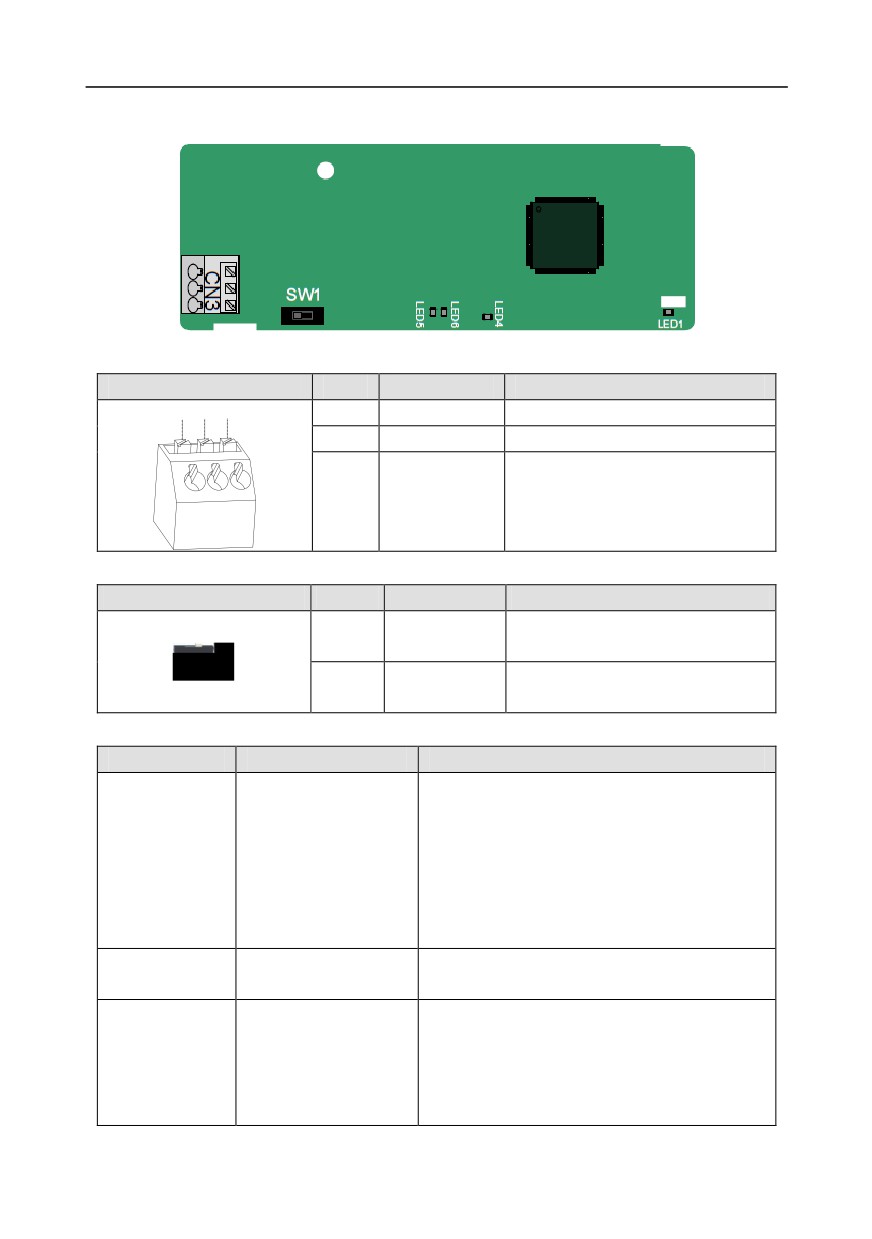
3-pin spring terminal
Pin
Function
Description
1
2
3
1
CANH
CANopen bus high level signal
2
CANG
CANopen bus shielding
3
CANL
CANopen bus low level signal
Terminal resistor switch function description
Terminal resistor switch
Position
Function
Description
CAN_H and CAN_L are not
Left
OFF
connected to a terminal resistor.
CAN_H and CAN_L are connected to
Right
ON
a terminal resistor of 120 Ω.
Indicator definition
Indicator No.
Definition
Function
This indicator is on when the extension card is
establishing a connection with the control board;
it blinks periodically after the extension card is
LED1
State indicator
properly connected to the control board (the
period is 1s, on for 0.5s, and off for the other
0.5s); and it is off when the extension card is
disconnected from the control board.
This indicator is on after the control board feeds
LED4
Power indicator
power to the communication card.
This indicator is on when the communication
card is in the working state.
LED5
Running indicator
It is off when a fault occurs. Check whether the
reset pin of the communication card and the
power supply are properly connected.
-297-
Appendix A
Indicator No.
Definition
Function
It blinks when the communication card is in the
pre-operation state.
It blinks once when the communication card is in
the stopped state.
This indicator is on when the CAN controller bus
is off or a fault occurs on the inverter.
It is off when the communication card is in the
LED6
Error indicator
working state.
It blinks when the address setting is incorrect.
It blinks once when a received frame is missed
or an error occurs during frame receiving.
For details about the operation, see the Goodrive350 Series Inverter Communication Extension Card
Operation Manual.
A.6.3 Ethernet communication card--EC-TX504
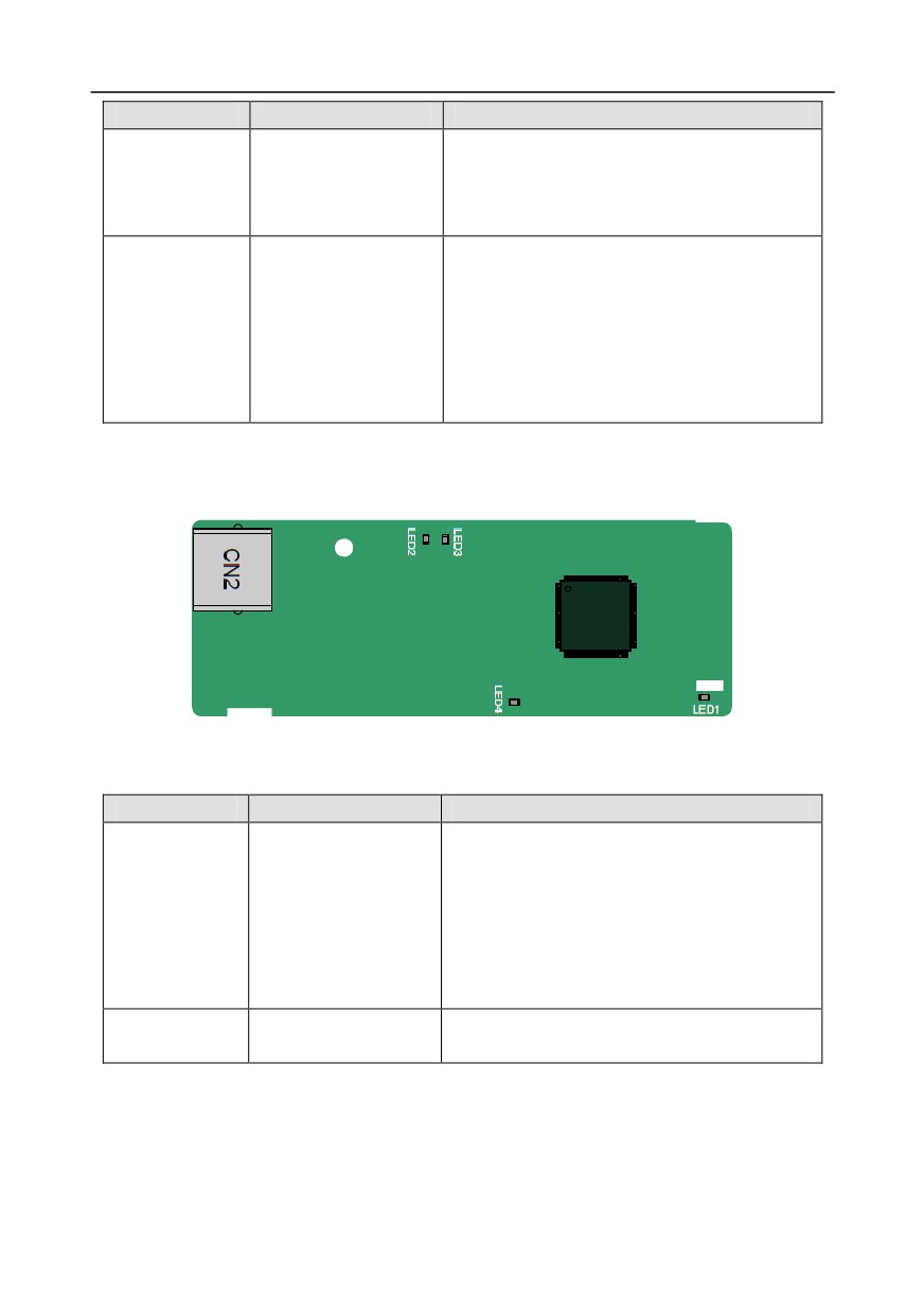
The EC-TX504 communication card adopts standard RJ45 terminals.
Indicator definition
Indicator No.
Definition
Function
This indicator is on when the extension card is
establishing a connection with the control board;
it blinks periodically after the extension card is
LED1
State indicator
properly connected to the control board (the
period is 1s, on for 0.5s, and off for the other
0.5s); and it is off when the extension card is
disconnected from the control board.
This indicator is on after the control board feeds
LED4
Power indicator
power to the communication card.
-298-
Appendix A
A.6.4 PROFIBUS-DP communication card--EC-TX503
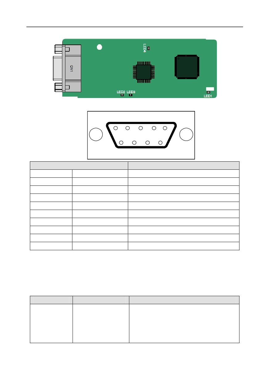
CN1 is a 9-pin D-type connector, as shown in the following figure.
5
4
3
2
1
9
8
7
6
Connector pin
Description
1
-
Unused
2
-
Unused
3
B-Line
Data+ (twisted pair 1)
4
RTS
Request sending
5
GND_BUS
Isolation ground
6
+5V BUS
Isolated power supply of 5 V DC
7
-
Unused
8
A-Line
Data- (twisted pair 2)
9
-
Unused
Housing
SHLD
PROFIBUS cable shielding line
+5V and GND_BUS are bus terminators. Some devices, such as the optical transceiver (RS485),
may need to obtain power through these pins.
On some devices, the transmission and receiving directions are determined by RTS. In normal
applications, only A-Line, B-Line, and the shield layer need to be used.
Indicator definition
Indicator No.
Definition
Function
This indicator is on when the extension card is
establishing a connection with the control board;
LED1
State indicator
it blinks periodically after the extension card is
properly connected to the control board (the
period is 1s, on for 0.5s, and off for the other
-299-
Appendix A
Indicator No.
Definition
Function
0.5s); and it is off when the extension card is
disconnected from the control board.
This indicator is on when the communication
card is online and data exchange can be
LED2
Online indicator
performed.
It is off when the communication card is not in
the online state.
This indicator is on when the communication
card is offline and data exchange cannot be
performed.
It blinks when the communication card is not in
the offline state.
It blinks at the frequency of 1 Hz when a
configuration error occurs: The length of the user
parameter data set during the initialization of the
communication card is different from that during
the network configuration.
LED3
Offline/Fault indicator
It blinks at the frequency of 2 Hz when user
parameter data is incorrect: The length or
content of the user parameter data set during
the initialization of the communication card is
different from that during the network
configuration.
It blinks at the frequency of 4 Hz when an error
occurs in the ASIC initialization of PROFIBUS
communication.
It is off when the diagnosis function is disabled.
This indicator is on after the control board feeds
LED4
Power indicator
power to the communication card.
For details about the operation, see the Goodrive350 Series Inverter Communication Extension Card
Operation Manual.
A.6.5 PROFINET communication card——EC- TX509
-300-
Appendix A
The terminal CN2 adopts a standard RJ45 interface, where CN2 is the dual RJ45 interface, and these
two RJ45 interfaces are not distinguished from each other and can be interchangeably inserted. They
are arranged as follows:
Pin
Name
Description
1
n/c
Not connected
2
n/c
Not connected
3
RX-
Receive Data-
4
n/c
Not connected
5
n/c
Not connected
6
RX+
Receive Data+
7
TX-
Transmit Data-
8
TX+
Transmit Data+
Definition of the state indicator
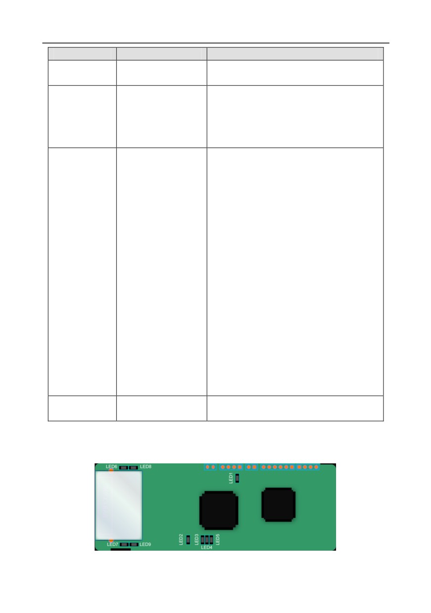
The PROFINET communication card has 9 indicators, of which LED1 is the power indicator, LED2-5
are the communication state
indicators of the communication card, and LED6-9 are the state
indicators of the network port.
LED
Color
State
Description
LED1
Green
3.3V power indicator
On
No network connection
The connection to the network cable
between the Profinet controller is OK,
LED2
Blinking
Red
but the communication is not
(Bus state indicator)
established.
Communication with the Profinet
Off
controller has been established
LED3
On
Profinet diagnosis exists
Green
(System fault indicator)
Off
No Profinet diagnosis
On
TPS-1 protocol stack has started
LED4
Green
Blinking
TPS-1 waits for MCU initialization
(Slave ready indicator)
Off
TPS-1 protocol stack does not start
LED5
Manufacturer-specific - depending on
(Maintenance state
Green
the characteristics of the device
indicator)
PROFINET communication card and
LED6/7
On
PC/PLC have been connected via a
(Network port state
Green
network cable
indicator)
PROFINET communication card and
Off
PC/PLC have not been connected yet
LED8/9
Green
Blinking
PROFINET communication card and
-301-
Appendix A
LED
Color
State
Description
(Network port
PC/PLC are communicating
communication
PROFINET communication card and
Off
indicator)
PC/PLC are not yet communicating
Electrical connection:
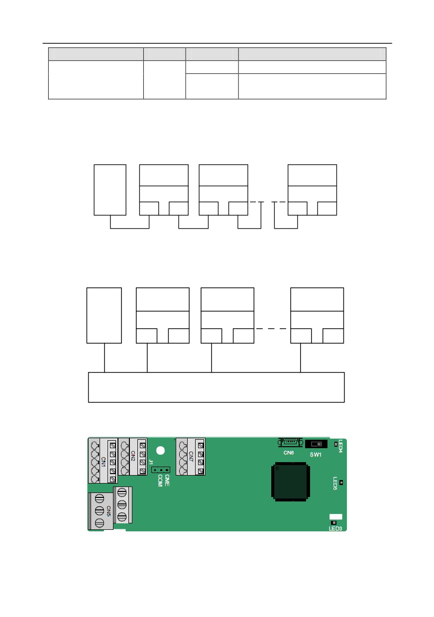
The Profinet communication card adopts a standard RJ45 interface, which can be used in a linear
network topology and a star network topology. The linear network topology electrical connection
diagram is shown below.
Slave device 1
Slave device 2
Slave device n
Master
device
RJ45
RJ45
RJ45
RJ45
RJ45
RJ45
Linear network topology electrical connection diagram
Note: For the star network topology, users need to prepare Profinet switches.
The star network topology electrical connection diagram is shown below:
Slave device 1
Slave device 2
Slave device n
Master
device
RJ45
RJ45
RJ45
RJ45
RJ45
RJ45
Switch
A.7 Programmable extension card function description
A.7.1 Programmable extension card--EC-PC501-00
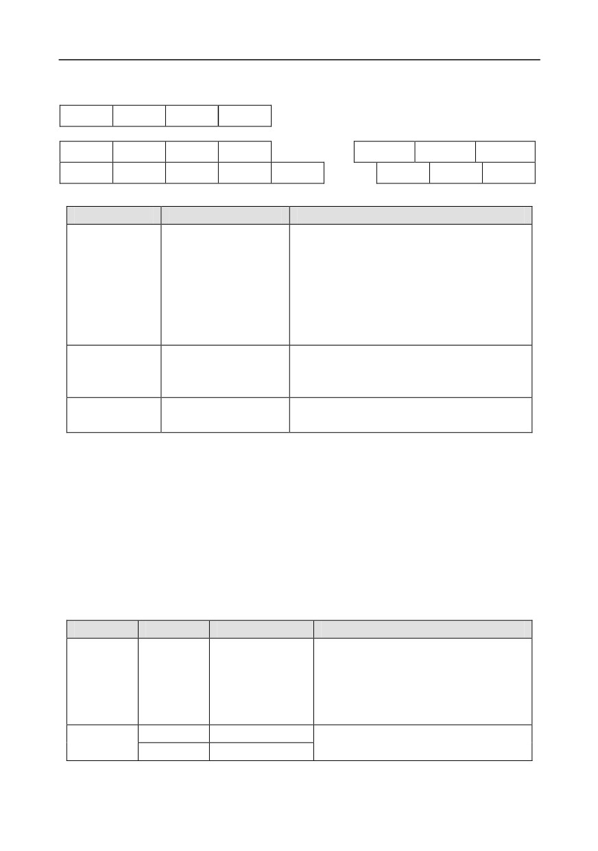
The terminals are arranged as follows:
SW1 is the start/stop switch of the programmable extension card. CN6 is the program download port,
-302-
Appendix A
and you can connect to a computer by using a standard USB cable. COM and CME are shorted
through J1 before delivery.
PY1
PY2
CME
COM
COM
PS1
PS2
PS3
PRO1A
PRO1B
PRO1C
PW
+24V
PS4
PS5
PS6
PRO2A
PRO2C
Indicator definition
Indicator No.
Definition
Function
This indicator is on when the extension card is
establishing a connection with the control board;
it blinks periodically after the extension card is
LED3
State indicator
properly connected to the control board (the
period is 1s, on for 0.5s, and off for the other
0.5s); and it is off when the extension card is
disconnected from the control board.
This indicator is on when the DIP switch is
PLC running state
LED4
turned to RUN (run the PLC); and it is off when
indicator
the switch is turned to STOP (stop the PLC).
This indicator is on after the control board feeds
LED5
Power indicator
power to the communication card.
The EC-PC501-00 programmable extension card can replace some micro PLC applications. It adopts
the global mainstream development environment CODESYS, supporting six types of programming
languages, namely the instruction language (IL), structural text (ST), function block diagram (FBD),
ladder diagram (LD), continuous function chart (CFC), and sequential function chart (SFC). It
provides a user program storage space of 128 kB and data storage space of 64 kB, which facilitates
customers' secondary development and meets the customization requirements.
The EC-PC501-00 programmable extension card provides 6 digital inputs, 2 digital outputs, and 2
relay outputs. It is user-friendly, providing relay outputs through European-type screw terminals and
other inputs and outputs through spring terminals.
EC-PC501-00 terminal function description
Category
Label
Name
Function description
The working power of digital input is
provided by an external power supply.
Power
PW
External power
Voltage range: 12-24 V
The terminals PW and +24V are shorted
before delivery.
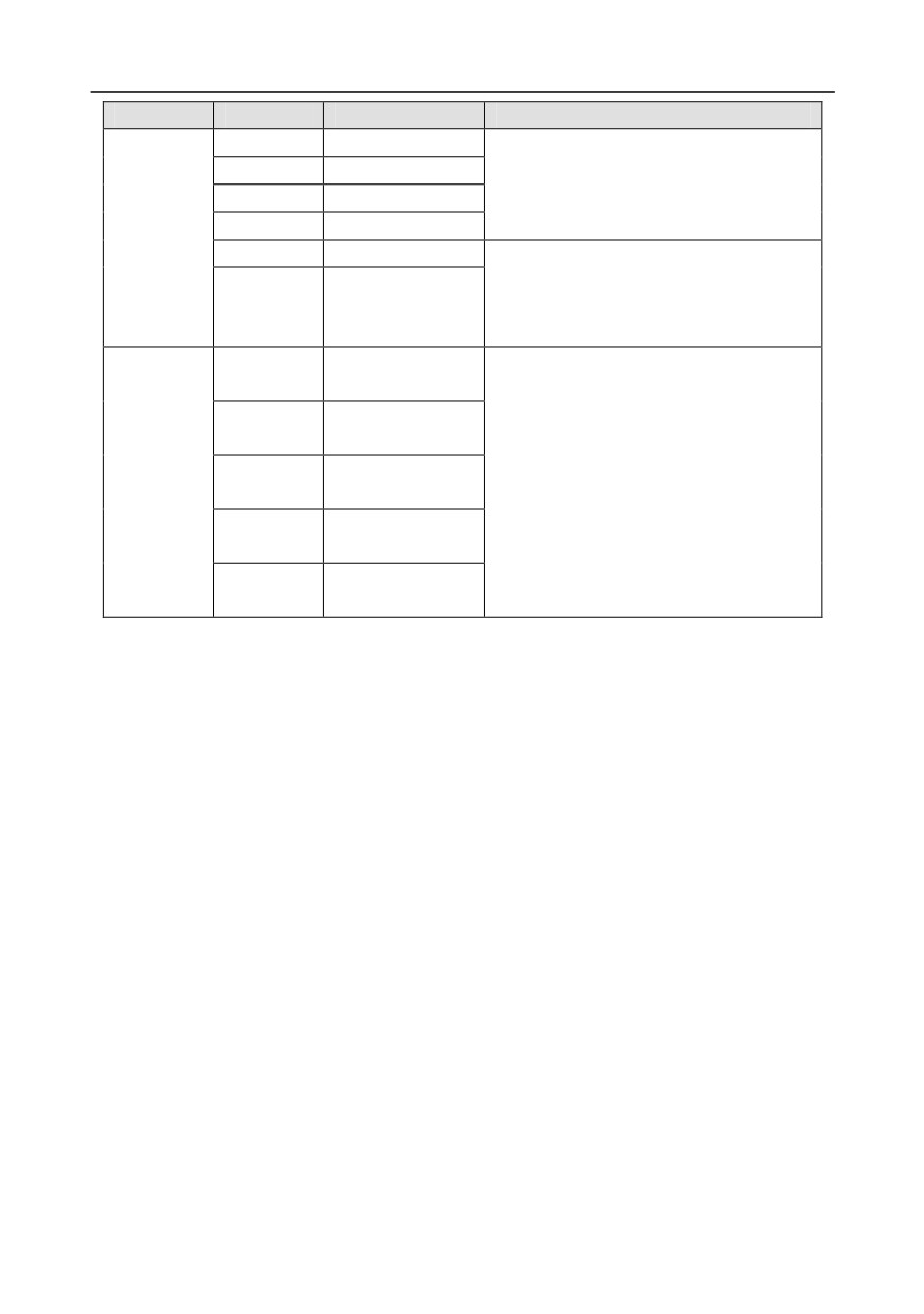
Digital
PS1—COM
Digital input 1
1. Internal impedance: 3.3 kΩ
input/output
PS2—COM
Digital input 2
2. Allowable voltage input: 12-30 V
-303-
Appendix A
Category
Label
Name
Function description
PS3—COM
Digital input 3
3. Bidirectional terminal
PS4—COM
Digital input 4
4. Max. input frequency: 1 kHz
PS5—COM
Digital input 5
PS6—COM
Digital input 6
PY1—CME
Digital output 1
1. Switch capacity: 200 mA/30 V
2. Output frequency range: 0-1 kHz
PY2—CME
Digital output 2
3. The terminals CME and COM are
shorted through J1 before delivery.
NO contact of
PR01A
relay 1
NC contact of
PR01B
relay 1
1. Contact capacity: 3A/AC 250 V, 1 A/DC
Relay
Common contact
30 V
PR01C
output
of relay 1
2. Do not use them as high-frequency
NO contact of
digital outputs.
PR02A
relay 2
Common contact
PR02C
of relay 2
For details about the operation of programmable extension cards, see the Goodrive350 Series
Inverter Communication Extension Card Operation Manual.
-304-
Appendix B
Appendix B Technical data
B.1 What this chapter contains
This chapter describes the technical data of the inverter and its compliance to CE and other quality
certification systems.
B.2 Derated application
B.2.1 Capacity
Choose an inverter based on the rated current and power of the motor. To endure the rated power of
the motor, the rated output current of the inverter must be larger or equal to the rated current of the
motor. The rated power of the inverter must be higher or equal to that of the motor.
Note:
1. The maximum allowable shaft power of the motor is limited to 1.5 times the rated power of the
motor. If the limit is exceeded, the inverter automatically restricts the torque and current of the
motor. This function effectively protect the input shaft against overload.
2. The rated capacity is the capacity at the ambient temperature of 40°C.
3. You need to check and ensure that the power flowing through the common DC connection in the
common DC system does not exceed the rated power of the motor.
B.2.2 Derating
If the ambient temperature on the site where the inverter is installed exceeds 40°C, the altitude
exceeds 1000 m, or the switching frequency is changed from 4 kHz to 8, 12, or 15 kHz, the inverter
needs to be derated.
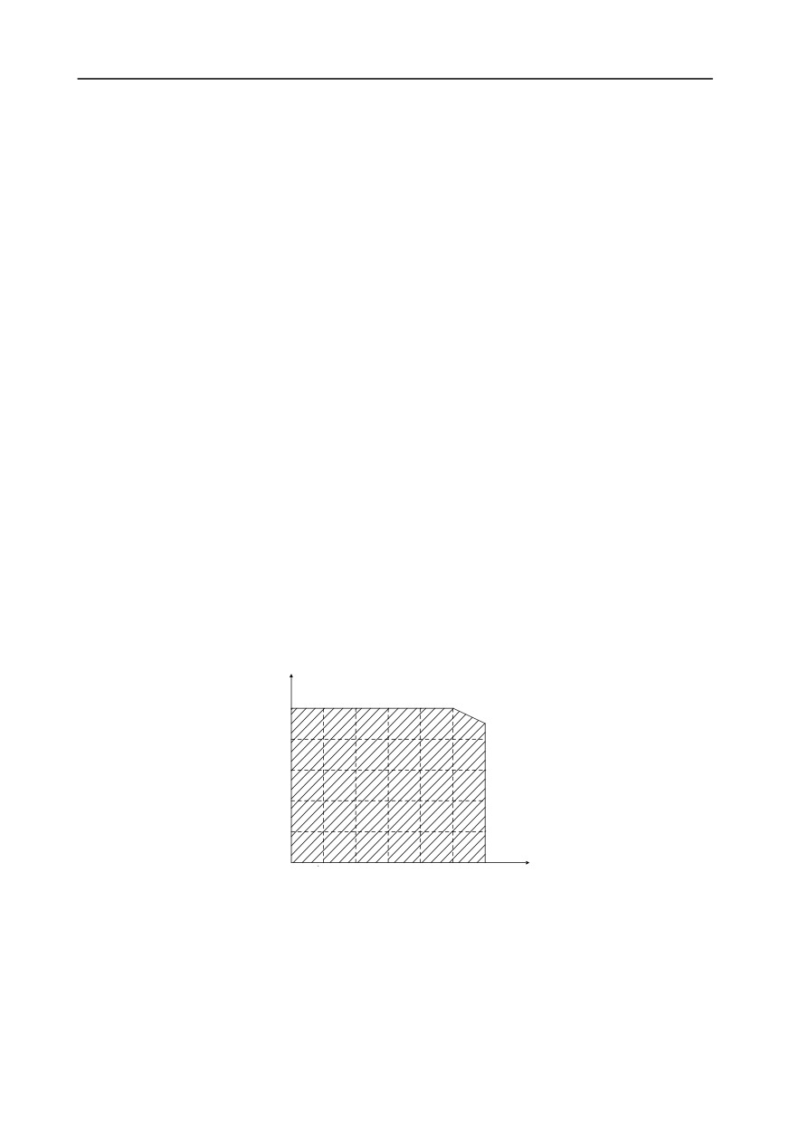
B.2.2.1 Derating due to temperature
When the temperature ranges from +40°C to +50°C, the rated output current is derated by 1% for
each increased 1°C. For the actual derating, see the following figure.
Derating coefficient (%)
100
90
80
60
40
20
Temperature (℃)
-10
0
10
20
30
40
50
Note: It is not recommended to use the inverter at a temperature higher than 50°C. If you do, you
shall be held accountable for the consequences caused.
B.2.2.2 Derating due to altitude
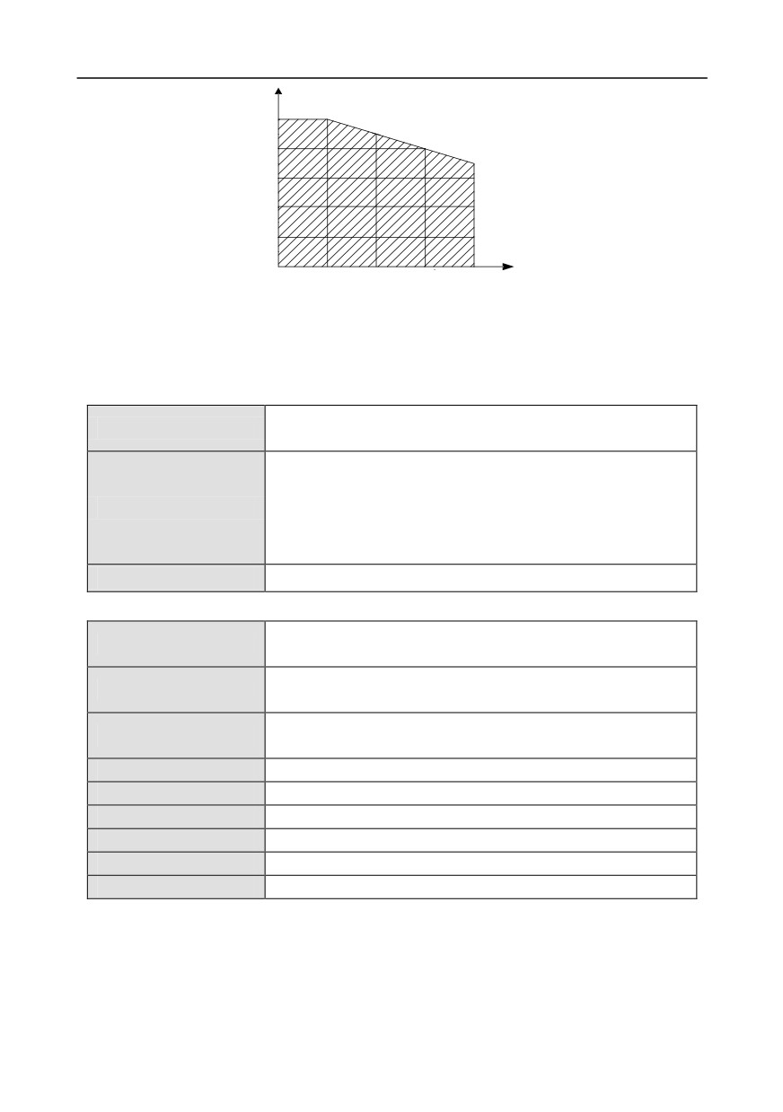
When the altitude of the site where the inverter is installed is lower than 1000 m, the inverter can run
at the rated power. If the altitude is higher than 1000 m, the allowable output power is derated. For
details about the derating, see the following figure.
-305-
Appendix B
Derating coefficient (%)
100
80
60
40
20
Altitude (m)
0
1000
2000
3000
4000
B.2.2.3 Derating due to carrier frequency
The power of Goodrive350 series inverters varies according to carrier frequencies. The rated power
of an inverter is defined based on the carrier frequency set in factory. If the carrier frequency exceeds
the factory setting, the power of the inverter is derated by 10% for each increased 1 kHz.
B.3 Grid specifications
AC 3PH 380V (-15%)-440V (+10%)
Grid voltage
AC 3PH 520V (-15%)-690V (+10%)
According to the definition in IEC 60439-1, the maximum allowable
short-circuit current at the incoming end is 100 kA. Therefore, the
Short-circuit capacity
inverter is applicable to scenarios where the transmitted current in
the circuit is no larger than 100 kA when the inverter runs at the
maximum rated voltage.
Frequency
50/60 Hz±5%, with a maximum change rate of 20%/s
B.4 Motor connection data
asynchronous induction motor or permanent-magnet synchronous
Motor type
motor
0-U1 (rated voltage of the motor), 3PH symmetrical, Umax (rated
Voltage
voltage of the inverter) at the field-weakening point
The short-circuit protection for the motor output meets the
Short-circuit protection
requirements of IEC 61800-5-1.
Frequency
0-400 Hz
Frequency resolution
0.01 Hz
Current
See the rated current.
Power limit
1.5 times of the rated power of the motor
Field-weakening point
10-400 Hz
Carrier frequency
4, 8, 12, or 15 kHz
B.4.1 EMC compatibility and motor cable length
The following table describes the maximum motor cable lengths that meet the requirements of the EU
EMC directive (2004/108/EC) when the carrier frequency is 4 kHz.
-306-
Appendix B
All models (with external EMC filters)
Maximum motor cable length (m)
Environment category II (C3)
30
Environment category I (C2)
30
You can learn the maximum length of the motor cable through the running parameters of the inverter.
To understand the accurate maximum cable length for using an external EMC filter, contact the local
INVT office.
For description about the environments categories I (C2) and II (C3), see section "EMC regulations".
B.5 Application standards
The following table describes the standards that the inverters comply with.
Safety of machinery--Safety-related parts of control systems--Part
EN/ISO 13849-1:2008
1: General principles for design
Safety of machinery--Electrical equipment of machines. Part
1:
IEC/EN 60204-1:2006
General requirements
Safety of machinery--Safety-related functional safety of electrical,
IEC/EN 62061:2005
electronic, and programmable electronic control systems
Adjustable speed electrical power drive systems--Part
3:EMC
IEC/EN 61800-3:2004
requirements and specific test methods
IEC/EN
Adjustable speed electrical power drive systems--Part 5-1: Safety
61800-5-1:2007
requirements—Electrical, thermal and energy
IEC/EN
Adjustable speed electrical power drive systems--Part 5-2: Safety
61800-5-2:2007
requirements--Function
B.5.1 CE marking
The CE marking on the name plate of an inverter indicates that the inverter is CE-compliant, meeting
the regulations of the European low-voltage directive
(2006/95/EC) and EMC directive
(2004/108/EC).
B.5.2 EMC compliance declaration
European union (EU) stipulates that the electric and electrical devices sold in Europe cannot generate
electromagnetic disturbance that exceeds the limits stipulated in related standards, and can work
properly in environments with certain electromagnetic interference. The EMC product standard (EN
61800-3:2004) describes the EMC standards and specific test methods for adjustable speed
electrical power drive systems. Products must strictly follow these EMC regulations.
B.6 EMC regulations
The EMC product standard (EN 61800-3:2004) describes the EMC requirements on inverters.
Application environment categories
Category I: Civilian environments, including application scenarios where inverters are directly
connected to the civil power supply low-voltage grids without intermediate transformers
Category II: All environments except those in Category I.
Inverter categories
-307-
Appendix B
C1: Rated voltage lower than 1000 V, applied to environments of Category I.
C2: Rated voltage lower than 1000 V, non-plug, socket, or mobile devices; power drive systems that
must be installed and operated by specialized personnel when applied to environments of Category I
Note: The EMC standard IEC/EN 61800-3 no longer restricts the power distribution of inverters, but it
specifies their use, installation, and commissioning. Specialized personnel or organizations must
have the necessary skills (including the EMC-related knowledge) for installing and/or performing
commissioning on the electrical drive systems.
C3: Rated voltage lower than 1000 V, applied to environments of Category II. They cannot be applied
to environments of Category I.
C4: Rated voltage higher than 1000 V, or rated current higher or equal to 400 A, applied to complex
systems in environments of Category II.
B.6.1 Inverter category of C2
The induction disturbance limit meets the following stipulations:
1. Select an optional EMC filter according to Appendix D and install it following the description in the
EMC filter manual.
2. Select the motor and control cables according to the description in the manual.
3. Install the inverter according to the description in the manual.
4. For the maximum length of the motor cable when the switching frequency is 4 kHz, see section
"EMC compatibility and motor cable length".
Currently in environments in China, the inverter may generate radio
interference, you need to take measures to reduce the interference.
B.6.2 Inverter category of C3
The anti-interference performance of the inverter meets the requirements of environments Category II
in the IEC/EN 61800-3 standard.
The induction disturbance limit meets the following stipulations:
1. Select an optional EMC filter according to Appendix D and install it following the description in the
EMC filter manual.
2. Select the motor and control cables according to the description in the manual.
3. Install the inverter according to the description in the manual.
4. For the maximum length of the motor cable when the switching frequency is 4 kHz, see section
"EMC compatibility and motor cable length".
Inverters of C3 category cannot be applied to civilian low-voltage common
grids. When applied to such grids, the inverter may generate radio frequency
electromagnetic interference.
-308-

Appendix C
Appendix C Dimension drawings
C.1 What this chapter contains
This chapter describes the dimension drawings of Goodrive350 series inverters. The dimension unit
used in the drawings is mm.
C.2 Keypad structure
C.2.1 Structure diagram
Outer outline of the keypad
2-M3×8 tapping
Panel
Keypad
screw
28.5
71.3
2.5
16.8
2- ø4
19
20.4
58
71.3
Installation hole dimensions and diagram for key installation without bracket
Fig C.1 Keypad structure diagram
C.2.2 Keypad installation bracket
Note: When installing an external keypad, you can directly use threaded screws or a keypad bracket.
For inverters of 380 V, 1.5 to 75 kW, you need to use optional keypad installation brackets. For those
of 380 V, 90 to 500 kW and 660 V, 22 to 630 kW, you can use optional brackets or use the standard
keypad brackets externally.
103
98
4-R12
Keypad adapter bracket
Installation dimensions
Fig C.2 Keypad installation bracket (optional) for inverters of 380 V, 1.5 to 500 kW and 660 V, 22 to
630 kW
-309-
Appendix C
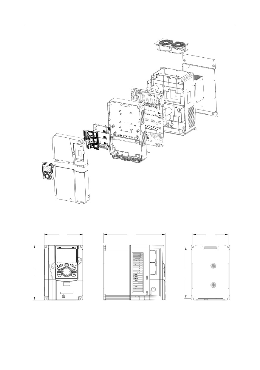
C.3 Inverter structure
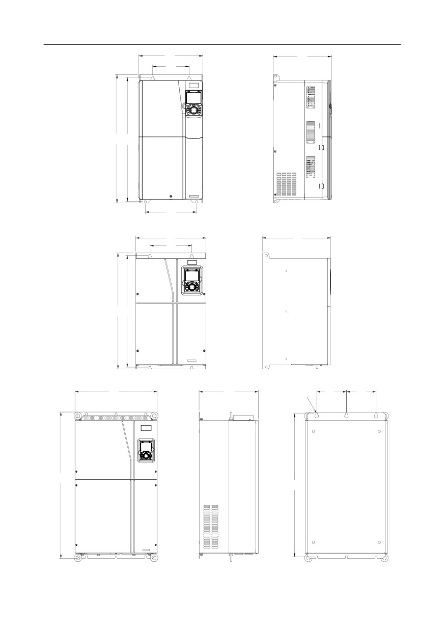
Fig C.3 Inverter structure diagram
C.4 Dimensions of Inverters of AC 3PH 380V (-15%)-440V (+10%)
C.4.1 Wall-mounting dimensions
W1
D1
W2
H1
H2
Fig C.4 Wall-mounting diagram of inverters of 380 V, 1.5 to 37 kW
-310-
Appendix C
W1
D1
W2
H1
H2
W3
Fig C.5 Wall-mounting diagram of inverters of 380 V, 45 to 75 kW
W1
D1
W2
H1 H2
Fig C.6 Wall-mounting diagram of inverters of 380 V, 90 to 110 kW
W1
D1
W2
W2
6- ø11.0
H1
H2
Fig C.7 Wall-mounting diagram of inverters of 380 V, 132 to 200 kW
-311-
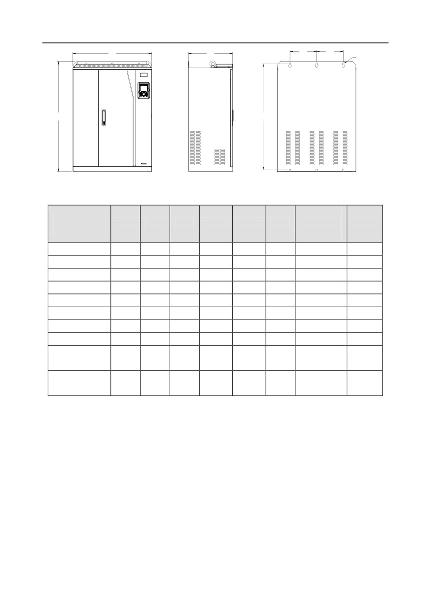
Appendix C
W1
D1
W2
W2
6- ø13.0
H1
H2
Fig C.8 Wall-mounting diagram of inverters of 380 V, 220 to 315 kW
Table C.1 Wall-mounting dimensions of 380 V inverters (unit: mm)
Installation
Fixing
Inverter
W1
W2
W3
H1
H2
D1
hole
screw
specification
diameter
1.5kW-2.2kW
126
115
-
186
175
185
5
M4
4kW-5.5kW
126
115
-
186
175
201
5
M4
7.5kW
146
131
-
256
243.5
192
6
M5
11kW-15kW
170
151
-
320
303.5
220
6
M5
18.5kW-22kW
200
185
-
340.6
328.6
208
6
M5
30kW-37kW
250
230
-
400
380
223
6
M5
45kW-75kW
282
160
226
560
542
258
9
M8
90kW-110kW
338
200
-
554
535
330
10
M8
132kW-
500
180
-
870
850
360
11
M10
200kW
220kW-
680
230
-
960
926
380
13
M12
315kW
-312-
Appendix C
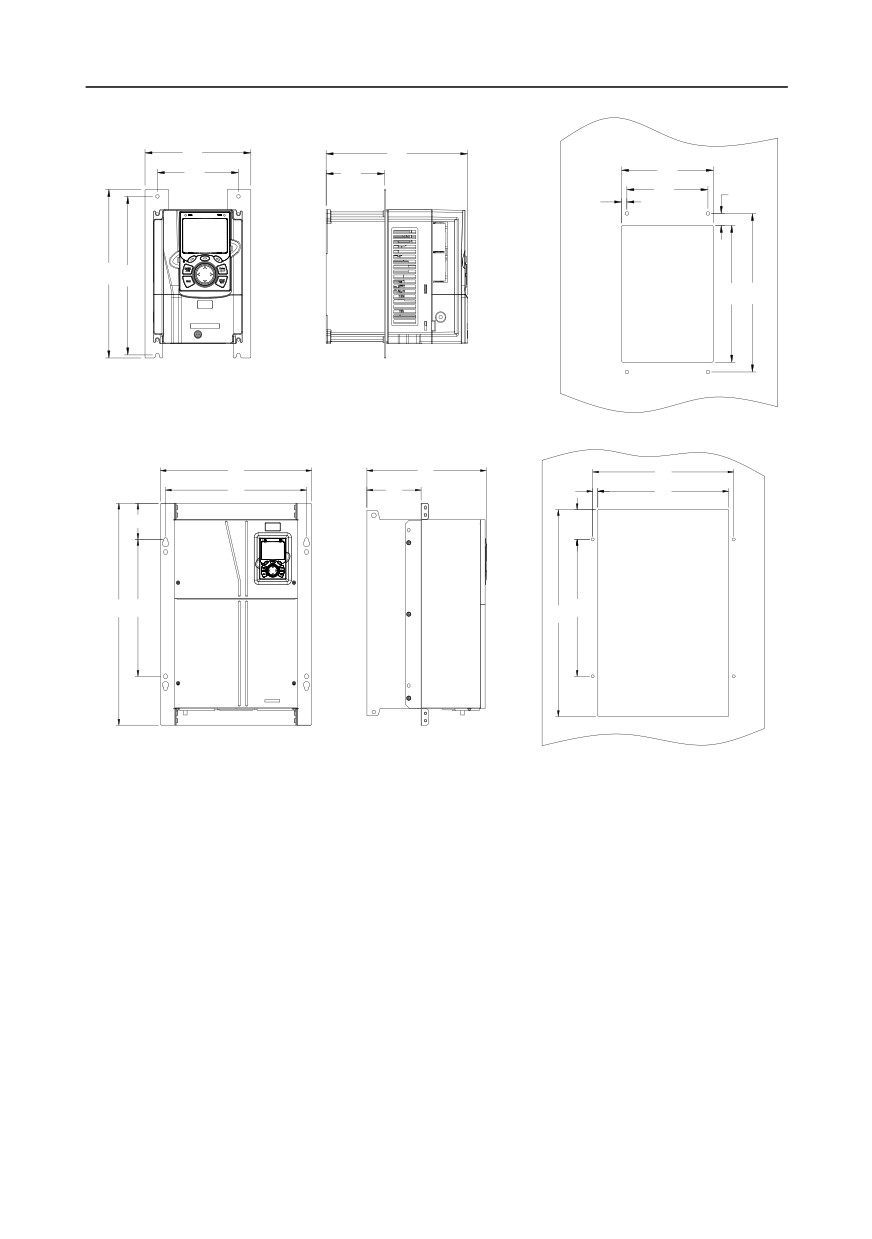
C.4.2 Flange installation dimensions
W1
D1
W2
D2
W3
W2
H4
W4
H1
H2
H3
H2
Fig C.9 Flange installation diagram of inverters of 380 V, 1.5 to 75 kW
W1
D1
W2
W2
D2
W4
W3
98.0
H4
H1
H2
H2
H3
Fig C.10 Flange installation diagram of inverters of 380 V, 90 to 110 kW
-313-
Appendix C
W3
W1
D1
W4
W2
W2
W2
W2
D2
H4
H1
H2
H2
H3
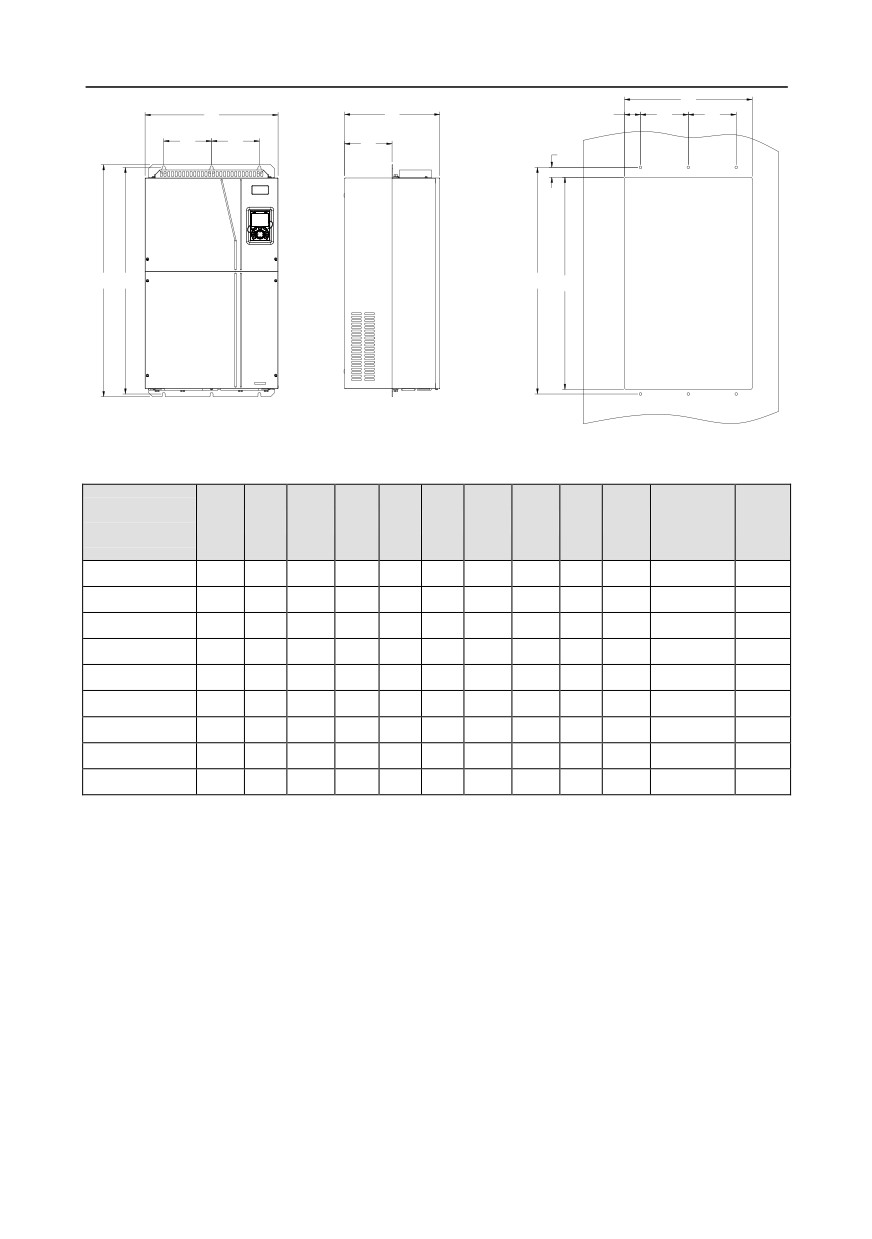
Fig C.11 Flange installation diagram of inverters of 380 V, 132 to 200 kW
Table C.2 Flange installation dimensions of 380 V inverters (unit: mm)
Installation
Fixing
Inverter
W1
W2
W3
W4
H1
H2
H3
H4
D1
D2
hole
screw
specification
diameter
1.5kW-2.2kW
150.2
115
130
7.5
234
220
190
13.5
185
65.5
5
M4
4kW-5.5kW
150.2
115
130
7.5
234
220
190
13.5
201
83
5
M4
7.5kW
170.2
131
150
9.5
292
276
260
6
192
84.5
6
M5
11kW-15kW
191.2
151
174
11.5
370
351
324
12
220
113
6
M5
18.5kW-22kW
266
250
224
13
371
250
350.6
20.3
208
104
6
M5
30kW-37kW
316
300
274
13
430
300
410
55
223
118.3
6
M5
45kW-75kW
352
332
306
12
580
400
570
80
258
133.8
9
M8
90kW-110kW
418.5
361
389.5
14.2
600
559
370
108.5
330
149.5
10
M8
132kW-200kW
500
180
480
60
870
850
796
37
360
178.5
11
M10
-314-