Goodrive350 Series High-performance Multi-function Inver ter. Operation manual - page 7
Chapter 7
Fault
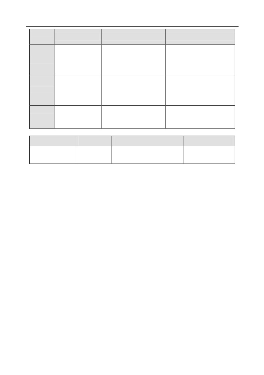
Fault type
Possible cause
Corrective measures
code
There is no data
Check whether the
DeviceNET card
transmission between the
communication card wiring is
E-DEV
communication
communication card and the
loose or dropped
timeout fault
host computer (or PLC)
Can master/slave
There is no data
Check whether the
communication card
transmission between the
communication card wiring is
ESCAN
communication
CAN master and slave
loose or dropped
timeout fault
communication cards
Master-slave
Detect the CAN slave inverter
Fault occurred to one of the
S-Err
synchronous CAN
and analyze the corresponding
CAN slave inverters
slave fault
fault cause of the inverter
7.5.2 Other state
Displayed code
State type
Possible cause
Solution
System power
The system is powered off or
Check the grid
PoFF
failure
the bus voltage is too low.
conditions.
-235-
Chapter 7
7.6 Analysis on common faults
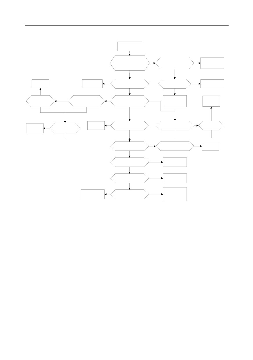
7.6.1 Motor fails to work
Motor fails to work
Whether the POWER
indicator is on?
No
Whether the air switch
No
Close the air
Whether the keypad
and EM contactor on the
contactor
displays information?
input side are closed?
Yes
Yes
Running
Rectify the fault
Yes
Whether fault information
Check the voltage
Normal
properly
based on the
is displayed?
of RST with a
Inverter fault
fault inforamtion
multimeter
No
Normal
Communication
Exception occurs
Whether it runs
No
Terminal
properly after the
Whether communication
Identify the channel of
Check the voltage
Running
parameters are
parameters are properly set?
running commands
of the grid
properly
reset?
Exception occurs
Yes
Keypad
Normal
normal
Normal
No
Whether it runs
Whether the
Running
Press RUN to run
Check whether the input terminal
properly after the
Running
communication wiring
properly
is in the correct state
terminal is closed?
properly
is performed properly?
Yes
Exception occurs
Exception occurs
Exception occurs
Whether the speed
Normal
No
Whether it runs properly after the
Normal
command is set
speed command is properly set?
running
properly?
Yes
Exception occurs
Check the voltage of
Inverter fault
UVW with a multimeter
Normal
Whether the motor is
No
Wire the motor
properly wired?
properly
Yes
No
Whether the load is too
Yes
Reduce the load if
Motor fault
the motor is locked
heavy?
due to heavy loads
-236-
Chapter 7
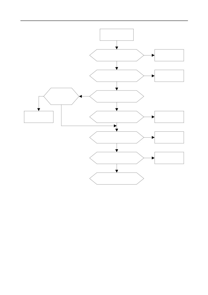
7.6.2 Motor vibrates
Motor vibrates or emits
an unusual sound
Whether the motor
No
Set the motor type
parameters and motor type
and parameters
are set correctly ?
correctly
Yes
Whether autotuning is
No
Perform autotuning
performed?
Yes
No
Whether the V/F
No
Whether it is vector
vibration parameter is
control?
set properly?
Yes
Yes
Whether the ASR and ACR
No
Set the parameters
Set the parameter
parameters are set
properly
properly
properly?
Yes
Whether unusual
Yes
Check the set
fluctuations occurs when it
frequency
runs at the set frequency?
No
Whether unusual
Yes
fluctuations occurs on the
Check the load
load?
No
If it is an inverter fault,
contact our company
-237-
Chapter 7
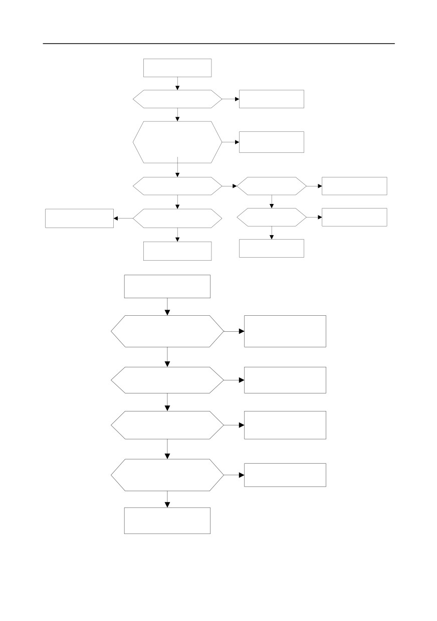
7.6.3 Overvoltage
Overvoltage fault
No
Whether the voltage of the power
Ensure the power supply
supply is within the standard range?
meets the requirement
Yes
Whether UVW on the output
side ofn the inverter is short to
Yes
Rectify the short-circuit
ground?
fault and perform the
Whether the wiring on the
wiring properly
output side of the inverter is
performed
properly?
Yes
Yes
Yes
Whether the ACC/DEC
Whether the ACC/DEC time
Prolong the ACC/DEC
time is too short?
can be prolonged?
time
No
No
Yes
Whether to use a
Yes
Check the load and adjust
Whether the loaded motor
Add brake accessories
is drived reversely?
brake accessory?
No
No
Adjust the brake
If it is an inverter fault,
accessories and
contact our company
resistance
7.6.4 Undervoltage
Undervoltage fault
Whether the voltage of the
Yes
Ensure the power supply
power supply is within the
meet the requirement
standard range?
No
Whether the air switch and
Yes
Close the air switch and
contactor are opened or
contactor; and rectify the
encounter exceptions?
exceptions
No
Whether a large-power device
Yes
Adjust the input of the
is running on the grid that pulls
grid
down the voltage of the grid?
No
Whether the inverter is
Yes
Identify the power-off
powered off during
causes, and rectify the
running?
exceptions
No
If it is an inverter fault,
contact our company
-238-
Chapter 7
7.6.5 Unusual heating of motor
Unusual heating of the
motor
Whether the motor
No
Set the motor
parameters are set
parameters
correctly?
correctly
Yes
Whether parameter
No
Parameter
autotuning is
autotune
performed?
Yes
No
Whether the inverter runs
at a low speed all the time?
Yes
Whether it is a variable-
No
Use a variable-
frequency motor?
frequency motor
Yes
Whether the load is
Yes
Reduce the
too heavy?
load
No
Whether the three
No
Replace the
phases of the motor are
motor
balanced?
Yes
Yes
Set the carrier
Whether the carrier
frequency
frequency is too low?
properly
No
Whether the motor
Yes
Add an output
cable is too long?
filter
No
If it is an inverter fault,
contact our company
-239-
Chapter 7
7.6.6 Inverter overheating
Inverter overheating
Whether the load is too
Yes
Reduce the load and
heavy or the capacity of
increase the capacity
the inverter is too small?
of the inverter
No
Whether the ambient
Yes
Add a cooling device
temperature is too
or derate the inverter
high?
No
Whether the fan of
Yes
If it is an inverter fault,
the inverter emits an
contact our company
unusual sound?
No
Yes
Clean the heat sink to
Whether the heat sink
improve the cooling
is blocked?
conditions
No
Whether the carrier
Yes
Reduce the carrier
frequency is too high?
frequency
No
If it is an inverter fault,
contact our company
-240-
Chapter 7
7.6.7 Motor stalls during ACC
Motor stalls during
ACC
Yes
Whether the ACC
Increase the ACC
time is too short?
time
No
Check the voltage of the
Yes
Use larger cables, shorten the
terminals of the motor with a
wiring distance, adjust the voltage
multimeter. Whether the voltage
drop of the output reactor, etc.
is within the defined range?
No
Whether the load
Yes
Yes
Whether a special
Contact our
or inertia is too
motor is used?
company
large?
No
No
Reduce the torque of
Reduce the inertia of
Yes
the load
and
Whether the load
the load and
increase the capacity
torque is too large?
increase the capacity
of the inverter
of the inverter
No
If it is an inverter fault
No
Whether the
Yes
Whether it is V/F
or interference,
torque boost
control?
contact our company
is too high?
Yes
No
Whether parameter
No
Modify the torque
autotuning is
Overcurrent
boost
performed?
Yes
If it is an inverter fault or
interference, contact our
company
-241-
Chapter 7
7.6.8 Overcurrent
Overcurrent
Whether UVW on the
output side of the inverter
Rectify the short-to-
is short to ground?
Yes
ground fault, and
Remove the motor cable
configure the motor
and checked whether it is
cables properly
connected to earth.
No
Whether the motor is
Yes
Replace the motor
short to ground?
No
Whether the motor type and
No
Set the motor type and
parameters are set correctly?
parameters correctly
Yes
Whether parameter
No
Perform parameter
autotuning is
autotuning
performed?
Yes
Whether the
Yes
Adjust the ACC/DEC
ACC/DEC time is too
time
short?
No
Whether the load is
Yes
Reduce the load and
increase the capacity of
too heavy?
the inverter
No
Whether there are
Yes
Remove the
interference sources?
interference sources
No
Decrease the torque
Yes
Whether the torque
Yes
Whether it is V/F
boost
boost is too high?
control?
No
No
No
Whether the multi-
No
Whether the ASR and ACR
Set the ASR and ACR
Adjust the V/F curve
dots V/F curve is set
parameters are set properly?
parameters properly
properly?
Yes
Yes
Set the
Yes
Whether unusual
If it is an inverter fault,
V/F vibration control
vibration occurs on
contact our company
parameters properly
the motor?
No
If it is an inverter fault,
contact our company
-242-
Chapter 7
7.7 Countermeasures on common interference
7.7.1 Interference on meter switches and sensors
Interference phenomenon
Pressure, temperature, displacement, and other signals of a sensor are collected and displayed by a
human-machine interaction device. The values are incorrectly displayed as follows after the inverter
is started:
1. The upper or lower limit is wrongly displayed, for example, 999 or -999.
2. The display of values jumps (usually occurring on pressure transmitters).
3. The display of values is stable, but there is a large deviation, for example, the temperature is
dozens of degrees higher than the common temperature (usually occurring on thermocouples).
4. A signal collected by a sensor is not displayed but functions as a drive system running feedback
signal. For example, an inverter is expected to decelerate when the upper pressure limit of the
compressor is reached, but in actual running, it starts to decelerate before the upper pressure
limit is reached.
5. After an inverter is started, the display of all kinds of meters (such as frequency meter and current
meter) that are connected to the analog output (AO) terminal of the inverter is severely affected,
displaying the values incorrectly.
6. Proximity switches are used in the system. After an inverter is started, the indicator of a proximity
switch flickers, and the output level flips.
Solution
1. Check and ensure that the feedback cable of the sensor is 20 cm or farther away from the motor
cable.
2. Check and ensure that the ground wire of the motor is connected to the PE terminal of the
inverter (if the ground wire of the motor has been connected to the ground block, you need to use
a multimeter to measure and ensure that the resistance between the ground block and PE
terminal is lower than 1.5 Ω).
3. Try to add a safety capacitor of 0.1 μF to the signal end of the feedback signal terminal of the
sensor.
4. Try to add a safety capacitor of 0.1 μF to the power end of the sensor meter (pay attention to the
voltage of the power supply and the voltage endurance of the capacitor).
5. For interference on meters connected to the AO terminal of an inverter, if AO uses current signals
of 0 to 20 mA, add a capacitor of 0.47 μF between the AO and GND terminals; and if AO uses
voltage signals of 0 to 10 V, add a capacitor of 0.1 μF between the AO and GND terminals.
Note:
1. When a decoupling capacitor is required, add it to the terminal of the device connected to the
sensor. For example, if a thermocouple is to transmit signals of 0 to 20 mA to a temperature meter,
-243-
Chapter 7
the capacitor needs to be added on the terminal of the temperature meter.; if an electronic ruler is
to transmit signals of 0 to 30 V to a PLC signal terminal, the capacitor needs to be added on the
terminal of the PLC.
2. If a large number of meters or sensors are disturbed. It is recommended that you configure an
external C2 filter on the input power end of the inverter. For models of filters, see section D.7.
7.7.2 Interference on communication
Interference phenomenon
The interference described in this section on 485 communication mainly includes communication
delay, out of sync, occasional power-off, or complete power-off that occurs after an inverter is started.
If the communication cannot be implemented properly, regardless of whether the inverter is running,
the exception is not necessarily caused by interference. You can find out the causes as follows:
1. Check whether the 485 communication bus is disconnected or in poor contact.
2. Check whether the two ends of line A or B are connected reversely.
3. Check whether the communication protocol (such as the baud rate, data bits, and check bit) of
the inverter is consistent with that of the upper computer.
If you are sure that communication exceptions are caused by interference, you can resolve the
problem through the following measures:
1. Simple inspection.
2. Arrange the communication cables and motor cables in different cable trays.
3. In multi-inverter application scenarios, adopt the chrysanthemum connection mode to connect
the communication cables between inverters, which can improve the anti-interference capability.
4. In multi-inverter application scenarios, check and ensure that the driving capacity of the master is
sufficient.
5. In the connection of multiple inverters, you need to configure one 120 Ω terminal resistor on each
end.
Solution
1. Check and ensure that the ground wire of the motor is connected to the PE terminal of the
inverter (if the ground wire of the motor has been connected to the ground block, you need to use
a multimeter to measure and ensure that the resistance between the ground block and PE
terminal is lower than 1.5 Ω).
2. Do not connect the inverter and motor to the same ground terminal as the upper computer. It is
recommended that you connect the inverter and motor to the power ground, and connect the
upper computer separately to a ground stud.
3. Try to short the signal reference ground terminal (GND) of the inverter with that of the upper
computer controller to ensure that ground potential of the communication chip on the control
board of the inverter is consistent with that of the communication chip of the upper computer.
-244-
Chapter 7
4. Try to short GND of the inverter to its ground terminal (PE).
5. Try to add a safety capacitor of 0.1 μF on the power terminal of the upper computer (PLC, HMI,
and touch screen). During this process, pay attention to the voltage of the power supply and the
voltage endurance capability of the capacitor. Alternatively, you can use a magnet ring (Fe-based
nanocrystalline magnet rings are recommended). Put the power L/N line or +/- line of the upper
computer through the magnet ring in the same direction and wind 8 coils around the magnet ring.
7.7.3 Failure to stop and indicator shimmering due to motor cable coupling
Interference phenomenon
1. Failure to stop
In an inverter system where an S terminal is used to control the start and stop, the motor cable and
control cable are arranged in the same cable tray. After the system is started properly, the S terminal
cannot be used to stop the inverter.
2. Indicator shimmering
After an inverter is started, the relay indicator, power distribution box indicator, PLC indicator, and
indication buzzer shimmers, blinks, or emits unusual sounds unexpectedly.
Solution
1. Check and ensure that the exception signal cable is arranged 20 cm or farther away from the
motor cable.
2. Add a safety capacitor of 0.1 μF between the digital input terminal (S) and the COM terminal.
3. Connect the digital input terminal (S) that controls the start and stop to other idle digital input
terminals in parallel. For example, if S1 is used to control the start and stop and S4 is idle, you
can try to connect connect S1 to S4 in parallel.
Note: If the controller (such as PLC) in the system controls more than 5 inverters at the same
time through digital input terminals (S), this scheme is not available.
7.7.4 Leakage current and interference on RCD
Inverters output high-frequency PWM voltage to drive motors. In this process, the distributed
capacitance between the internal IGBT of an inverter and the heat sink and that between the stator
and rotor of a motor may inevitably cause the inverter to generate high-frequency leakage current to
the ground. A residual current operated protective device
(RCD) is used to detect the
power-frequency leakage current when a grounding fault occurs on a circuit. The application of an
inverter may cause misoperation of a RCD.
1. Rules for selecting RCDs
(1)
Inverter systems are special. In these systems, it is required that the rated residual current of
common RCDs at all levels is larger than 200 mA, and the inverters are grounded reliably.
(2)
For RCDs, the time limit of an action needs to be longer than that of a next action, and the time
difference between two actions need to be longer than 20 ms. For example, 1s, 0.5s, and 0.2s.
(3)
For circuits in inverter systems, electromagnetic RCDs are recommended. Electromagnetic
-245-
Chapter 7
RCDs have strong anti-interference capability, and thus can prevent the impact of
high-frequency leakage current.
Electronic RCD
Electromagnetic RCD
Requiring highly sensitive, accurate, and
stable zero-phase sequence current
Low cost, high sensitivity, small in volume,
transformer, using permalloy
susceptible to voltage fluctuation of the grid
high-permeability materials, complex process,
and ambient temperature, weak
high cost, not susceptible to voltage
anti-interference capability
fluctuation of the power supply and ambient
temperature, strong anti- interference
capability
2. Solution to RCD misoperation (handling the inverter)
1.
Try to remove the jumper cap at "EMC/J10" on the middle casing of the inverter.
2.
Try to reduce the carrier frequency to 1.5 kHz (P00.14=1.5).
3.
Try to modify the modulation mode to "3PH modulation and 2PH modulation" (P8.40=0).
3. Solution to RCD misoperation (handling the system power distribution)
(1)
Check and ensure that the power cable is not soaking in water.
(2)
Check and ensure that the cables are not damaged or spliced.
(3)
Check and ensure that no secondary grounding is performed on the neutral wire.
(4)
Check and ensure that the main power cable terminal is in good contact with the air switch or
contactor (all screws are tightened).
(5)
Check 1PH powered devices, and ensure that no earth lines are used as neutral wires by these
devices.
(6)
Do not use shielded cables as inverter power cables and motor cables.
7.7.5 Live device chassis
Phenomenon
After an inverter is started, there is sensible voltage on the chassis, and you may feel an electric
shock when touching the chassis. The chassis, however, is not live (or the voltage is far lower than
the human safety voltage) when the inverter is powered on but not running.
Solution
1. If there is power distribution grounding or ground stud on the site, ground the cabinet chassis of
the drive system through the power ground or stud.
2. If there is no grounding on the site, you need to connect the motor chassis to the ground terminal
PE of the inverter, and ensure that the jumper at "EMC/J10" on the middle casing of the inverter
is shorted.
-246-
Chapter 8
Chapter 8 Maintenance and hardware fault diagnosis
8.1 What this chapter contains
This chapter describes how to carry out preventive maintenance on Goodrive350 series inverters.
8.2 Periodical inspection
Little maintenance is required when inverters are installed in environments that meet requirements.
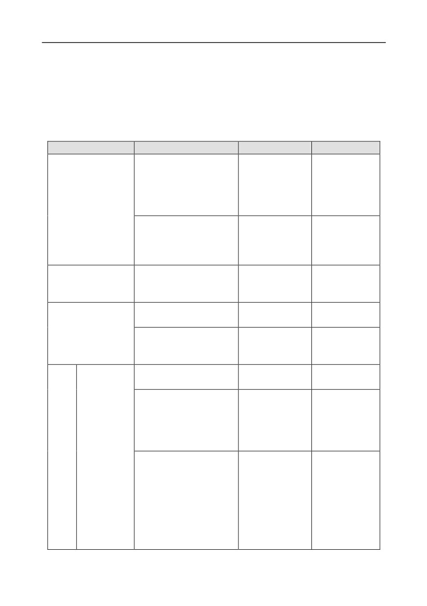
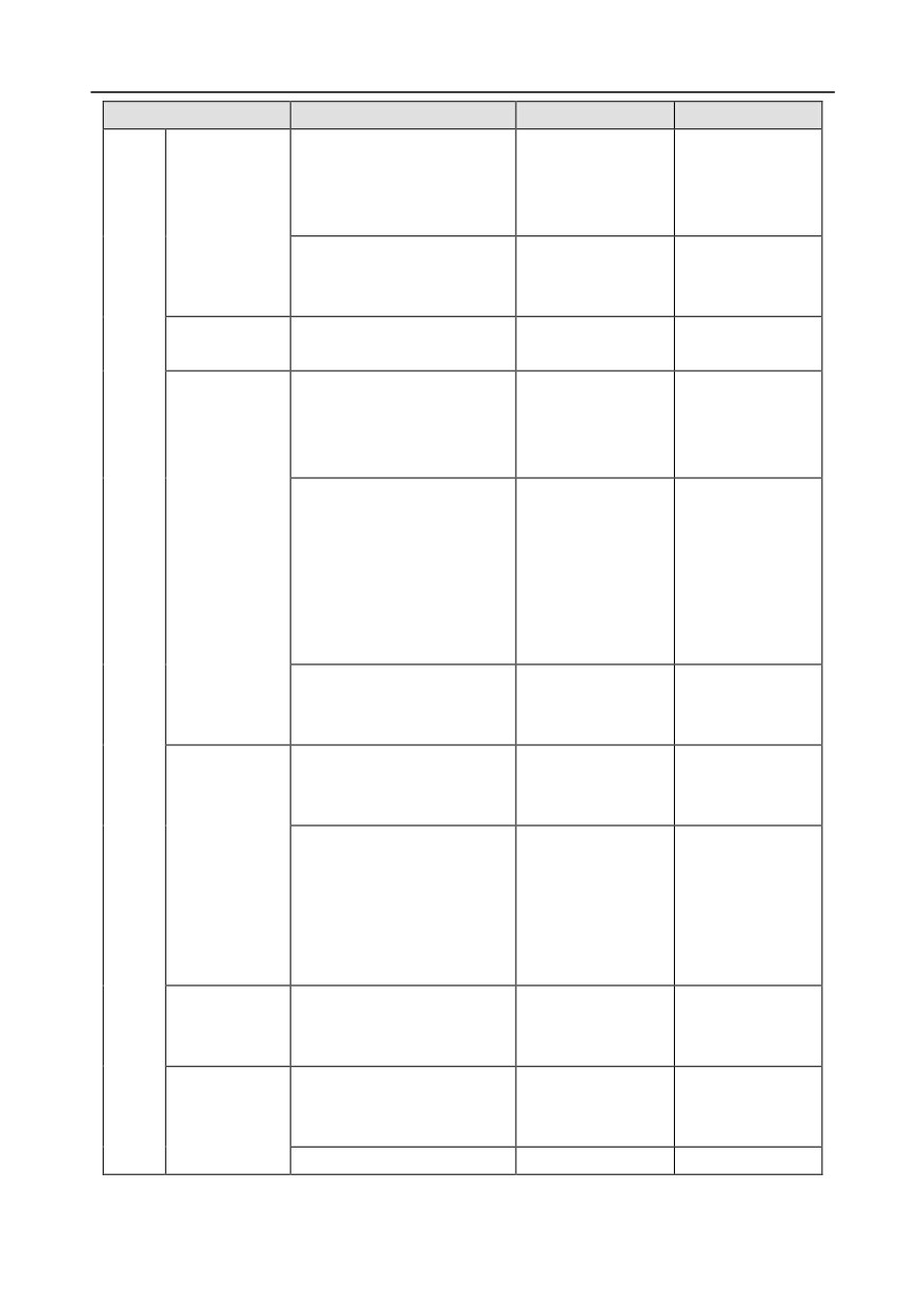
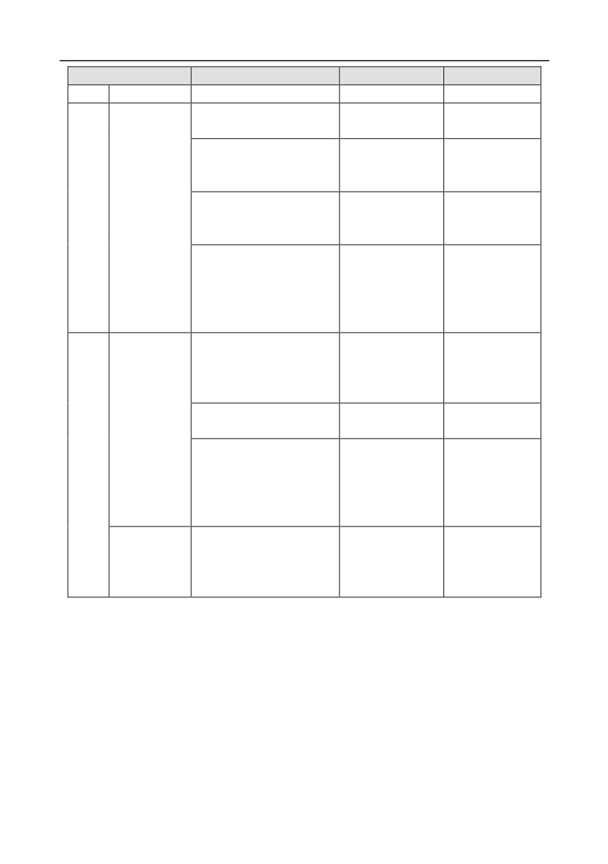
The following table describes the routine maintenance periods recommended by INVT.
Subject
Item
Method
Criterion
Check the temperature, and
humidity, and whether there is
Visual inspection,
The requirements
vibration, dust, gas, oil spray,
and use instruments
stated in this
and water droplets in the
for measurement.
manual are met.
Ambient environment
environment.
Check whether there are
There are no tools
foreign matters, such as tools,
or dangerous
Visual inspection
or dangerous substances
substances placed
placed nearby.
nearby.
Use multimeters or
The requirements
Check the voltage of the main
Voltage
other instruments for
stated in this
circuit and control circuit.
measurement.
manual are met.
Check the display of
The characters are
Visual inspection
information.
displayed properly.
Keypad
The requirements
Check whether characters are
Visual inspection
stated in this
not completely displayed.
manual are met.
Check whether the bolts
No exception
Screw them up.
loose or come off.
occurs.
Check whether the machine
is deformed, cracked, or
No exception
damaged, or their color
Visual inspection
occurs.
changes due to overheating
and aging.
Main
Common
No exception
circuit
occurs.
Note:
Check whether there are
Discoloration of
Visual inspection
stains and dust attached.
copper bars does
not mean that they
cannot work
properly.
-247-
Chapter 8
Subject
Item
Method
Criterion
Check whether the
conductors are deformed or
No exception
Visual inspection
their color change due to
occurs.
Conductor and
overheat.
wire
Check whether the wire
No exception
sheaths are cracked or their
Visual inspection
occurs.
color changes.
Check whether there is
No exception
Terminal block
Visual inspection
damage.
occurs.
Check whether there is
electrolyte leakage,
No exception
Visual inspection
discoloration, cracks, and
occurs.
chassis expansion.
Determine the
service life based on
the maintenance
Filter capacitor
Check whether the safety
No exception
information, or
valves are released.
occurs.
measure them
through electrostatic
capacity.
Check whether the
Use instruments to
Electrostatic
electrostatic capacity is
measure the
capacity ≥ initial
measured as required.
capacity.
value × 0.85
Check whether there is
Olfactory and visual
No exception
displacement caused due to
inspection
occurs.
overheat.
Visual inspection, or
Resistor
remove one end of
Resistance range:
Check whether the resistors
the connection cable
±10% (of the
are disconnected.
and use a
standard
multimeter for
resistance)
measurement.
Check whether there is
Auditory, olfactory,
Transformer
No exception
unusual vibration sounds or
and visual
and reactor
occurs.
smells.
inspection
Check whether there are
Electromagnetic
No exception
vibration sounds in the
Auditory inspection
contactor and
occurs.
workshop.
relay
Check whether the contacts
Visual inspection
No exception
-248-
Chapter 8
Subject
Item
Method
Criterion
are in good contact.
occurs.
Check whether the screws
No exception
Screw them up.
and connectors loose.
occurs.
Check whether there is
Olfactory and visual
No exception
unusual smell or
inspection
occurs.
discoloration.
Check whether there are
Control
Control PCB,
No exception
cracks, damage, deformation,
Visual inspection
circuit
connector
occurs.
or rust.
Visual inspection,
Check whether there is
and determine the
No exception
electrolyte leakage or
service life based on
occurs.
deformation.
the maintenance
information.
Auditory and visual
Check whether there are
inspection, and turn
The rotation is
unusual sounds or vibration.
the fan blades with
smooth.
your hand.
Check whether the bolts
No exception
Screw them up.
Cooling fan
loose.
occurs.
Visual inspection,
Cooling
Check whether there is
and determine the
system
No exception
decoloration caused due to
service life based on
occurs.
overheat.
the maintenance
information.
Check whether there are
foreign matters blocking or
No exception
Ventilation duct
Visual inspection
attached to the cooling fan, air
occurs.
inlets, or air outlets.
For more details about maintenance, contact the local INVT office, or visit our website
8.3 Cooling fan
The service life of the cooling fan of the inverter is more than 25,000 hours. The actual service life of
the cooling fan is related to the use of the inverter and the temperature in the ambient environment.
You can view the running duration of the inverter through P07.14 (Accumulated running time).
The increase of the bearing noise indicates a fan fault. If the inverter is applied in a key position,
replace the fan once the fan starts to generate unusual noise. You can purchase spare parts of fans
from INVT.
-249-
Chapter 8
Cooling fan replacement
Read the safety precautions carefully and follow the instructions to perform
operations. Otherwise, physical injuries or damage to the device may be
caused.
1. Stop the device, disconnect the AC power supply, and wait for a time no shorter than the waiting
time designated on the inverter.
2. Open the cable clamp to loose the fan cable (for inverters of 380 V, 1.5 to 30 kW, the middle
casing needs to be removed).
3. Remove the fan cable.
4. Remove the fan with a screwdriver.
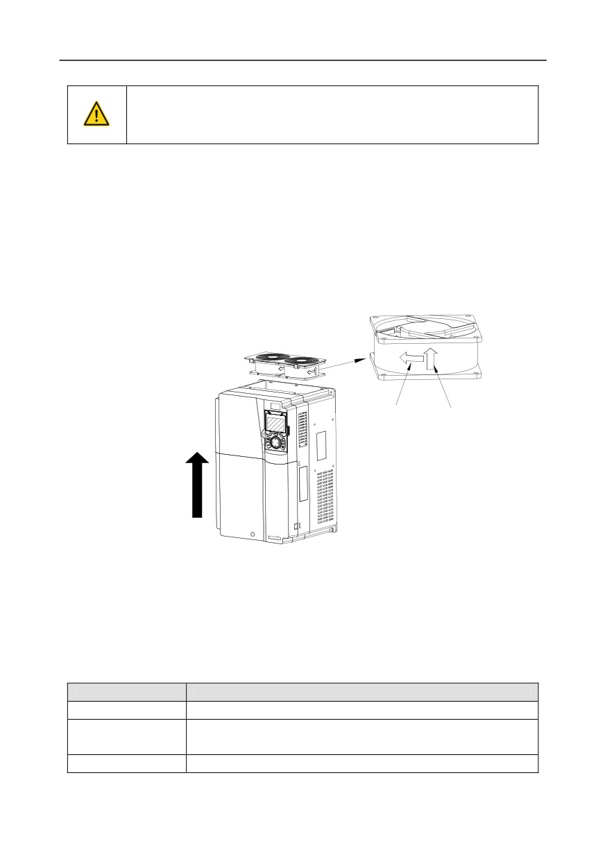
5. Install a new fan in the inverter in the reverse steps. Assemble the inverter. Ensure that the air
direction of the fan is consistent with that of the inverter, as shown in the following figure.
Rotating direction
Air direction
Air
direction
Fig 8.1 Fan maintenance for inverters of 7.5 kW or higher
6. Power on the inverter.
8.4 Capacitor
8.4.1 Capacitor reforming
If the inverter has been left unused for a long time, you need to follow the instructions to reform the
DC bus capacitor before using it. The storage time is calculated from the date the inverter is
delivered.
Storage time
Operation principle
Less than 1 year
No charging operation is required.
The inverter needs to be powered on for 1 hour before the first running
1 to 2 years
command.
2 to 3 years
Use a voltage controlled power supply to charge the inverter:
-250-
Chapter 8
Storage time
Operation principle
Charge the inverter at 25% of the rated voltage for 30 minutes, and
then charge it at 50% of the rated voltage for 30 minutes, at 75% for
another 30 minutes, and finally charge it at 100% of the rated voltage
for 30 minutes.
Use a voltage controlled power supply to charge the inverter:
Charge the inverter at 25% of the rated voltage for 2 hours, and then
More than 3 years
charge it at 50% of the rated voltage for 2 hours, at 75% for another 2
hours, and finally charge it at 100% of the rated voltage for 2 hours.
The method for using a voltage controlled power supply to charge the inverter is described as follows:
The selection of a voltage controlled power supply depends on the power supply of the inverter. For
inverters with an incoming voltage of 1PH/3PH 230 V AC, you can use a 230 V AC/2 A voltage
regulator. Both 1PH and 3PH inverters can be charged with a 1PH voltage controlled power supply
(connect L+ to R, and N to S or T). All the DC bus capacitors share one rectifier, and therefore they
are all charged.
For inverters of a high voltage class, ensure that the voltage requirement (for example, 380 V) is met
during charging. Capacitor changing requires little current, and therefore you can use a
small-capacity power supply (2 A is sufficient).
The method for using a resistor (incandescent lamp) to charge the drive is described as follows:
If you directly connect the drive device to a power supply to charge the DC bus capacitor, it needs to
be charged for a minimum of 60 minutes. The charging operation must be performed at a normal
indoor temperature without load, and you must connect a resistor in series mode in the 3PH circuit of
the power supply.
For a 380 V drive device, use a resistor of 1 kΩ/100W. If the voltage of the power supply is no higher
than 380 V, you can also use an incandescent lamp of 100W. If an incandescent lamp is used, it may
go off or the light may become very weak.
Resistor 1 KΩ/100 W
R
U
Power supply
Resistor 1 KΩ/100 W
S
Inverter
V
380 V
Resistor 1 KΩ/100 W
T
W
Fig 8.2 Charging circuit example of driving devices of 380 V
8.4.2 Electrolytic capacitor replacement
Read the safety precautions carefully and follow the instructions to perform
operations. Otherwise, physical injuries or damage to the device may be
caused.
The electrolytic capacitor of an inverter must be replaced if it has been used for more than 35,000
hours. For details about the replacement, contact the local INVT office.
-251-
Chapter 8
8.5 Power cable
Read the safety precautions carefully and follow the instructions to perform
operations. Otherwise, physical injuries or damage to the device may be
caused.
1. Stop the inverter, disconnect the power supply, and wait for a time no shorter than the waiting
time designated on the inverter.
2. Check the connection of the power cables. Ensure that they are firmly connected.
3. Power on the inverter.
-252-
Chapter 9
Chapter 9 Communication protocol
9.1 What this chapter contains
This chapter describes the communication protocol of Goodrive350 series products.
Goodrive350 series inverters provide RS485 communication interfaces and adopt the master-slave
communication based on the international standard Modbus communication protocol. You can
implement centralized control (setting commands for controlling the inverter, modifying the running
frequency and related function code parameters, and monitoring the working state and fault
information of the inverter) through PC/PLC, upper control computer, or other devices to meet specific
application requirements.
9.2 Modbus protocol introduction
Modbus is a software protocol, a common language used in electronic controllers. By using this
protocol, a controller can communicate with other devices through transmission lines. It is a general
industrial standard. With this standard, control devices produced by different manufacturers can be
connected to form an industrial network and be monitored in a centralized way.
The Modbus protocol provides two transmission modes, namely American Standard Code for
Information Interchange (ASCII) and remote terminal units (RTU). On one Modbus network, all the
device transmission modes, baud rates, data bits, check bits, end bits, and other basic parameters
must be set consistently.
A Modbus network is a control network with one master and multiple slaves, that is, on one Modbus
network, there is only one device serving as the master, and other devices are the slaves. The master
can communicate with one slave or broadcast messages to all the slaves. For separate access
commands, a slave needs to return a response. For broadcasted information, slaves do not need to
return responses.
9.3 Application of Modbus
Goodrive350 series inverters use the RTU mode provided by the Modbus protocol, and RS485
interfaces are used.
9.3.1 RS485
RS485 interfaces work in half-duplex mode and transmit data signals in the differential transmission
way, which is also referred to as balanced transmission. An RS485 interface uses a twisted pair,
where one wire is defined as A (+), and the other B (-). Generally, if the positive electrical level
between the transmission drives A and B ranges from +2 V to +6 V, the logic is "1"; and if it ranges
from -2 V to -6 V, the logic is "0".
The 485+ terminal on the terminal block of the inverter corresponds to A, and 485- corresponds to B.
The communication baud rate (P14.01) indicates the number of bits transmitted in a second, and the
unit is bit/s
(bps). A higher baud rate indicates faster transmission and poorer anti-interference
capability. When a twisted pair of 0.56 mm (24 AWG) is used, the maximum transmission distance
varies according to the baud rate, as described in the following table.
-253-
Chapter 9
Max. transmission
Max. transmission
Baud rate (bps)
Baud rate (bps)
distance
distance
2400
1800 m
9600
800 m
4800
1200 m
19200
600 m
When RS485 interfaces are used for long-distance communication, it is recommended that you use
shielded cables, and use the shield layer as the ground wires.
When there are fewer devices and the transmission distance is short, the whole network works well
without terminal load resistors. The performance, however, degrades as the distance increases.
Therefore, it is recommended that you use a 120 Ω terminal resistor when the transmission distance
is long.
9.3.1.1 Application to one inverter
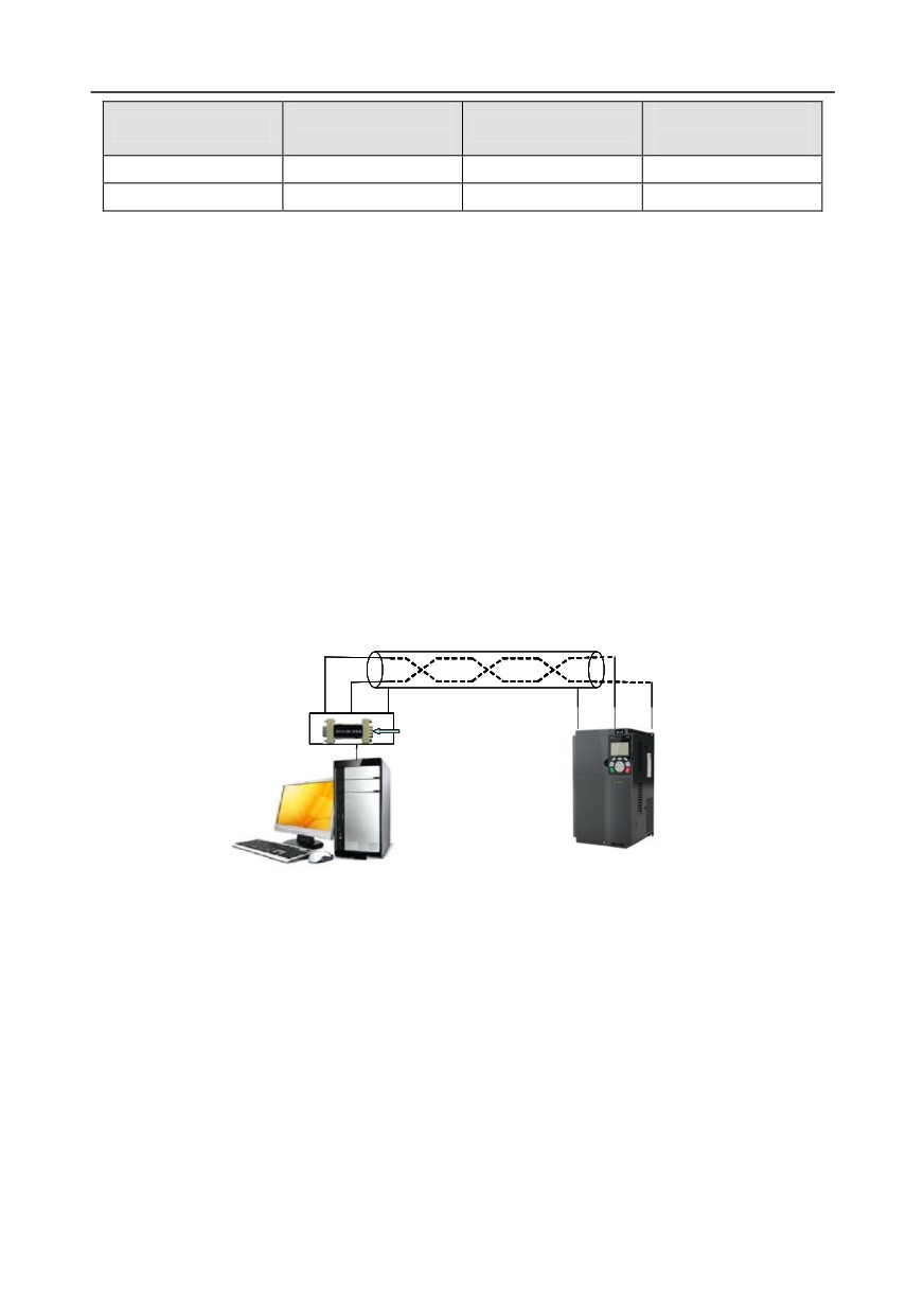
Fig 9.1 is the Modbus wiring diagram of one inverter and a PC. Generally, PCs do not provide RS485
interfaces, so you need to convert an RS232 interface or USB port of a PC to an RS485 interface.
Connect end A of the RS485 interface to the 485+ port on the terminal block of the inverter, and
connect end B to the 485- port. It is recommended that you use shielded twisted pairs. When an
RS232-RS485 converter is used, the cable used to connect the RS232 interface of the PC and the
converter cannot be longer than 15 m. Use a short cable when possible. It is recommended that you
insert the converter directly into the PC. Similarly, when a USB-RS485 converter is used, use a short
cable when possible.
Shielded twisted pair
B
A
A
B
Ground
RS485 line
Ground
485+
485-
RS232-RS485 converter
PC
Inverter
Fig 9.1 Wiring of RS485 applied to one inverter
9.3.1.2 Application to multiple inverters
In practical application to multiple inverters, chrysanthemum connection and star connection are
commonly used.
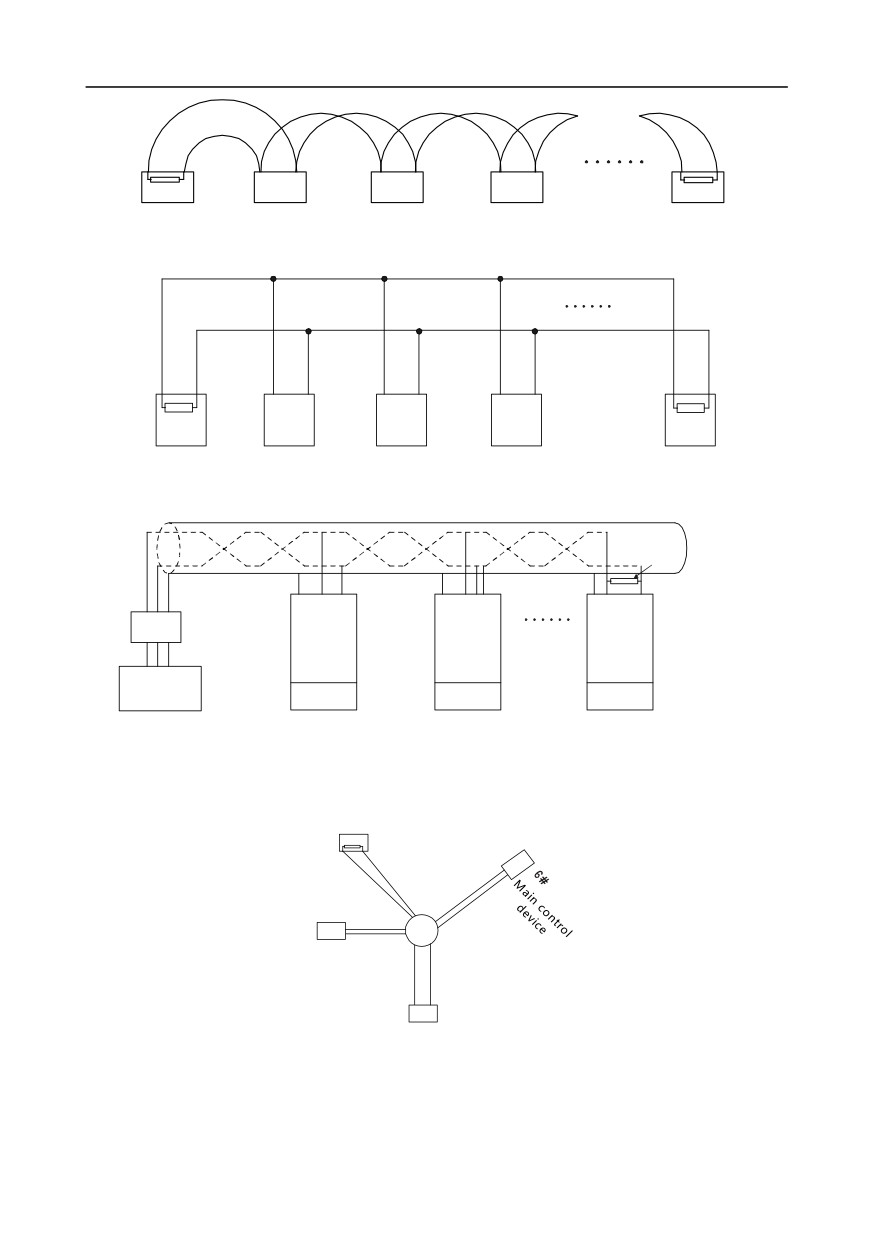
According to the requirements of the RS485 industrial bus standards, all the devices need to be
connected in chrysanthemum mode with one 120 Ω terminal resistor on each end, as shown in Fig
9.2. Fig 9.3 is the simplified wiring diagram, and Fig 9.4 is the practical application diagram.
-254-
Chapter 9
120Ω
120Ω
1#
2#
3#
4#
32 #
Fig 9.2 On-site chrysanthemum connection diagram
A+
B-
A+
B-
Master
1#
2#
3#
31#
Fig 9.3 Simplified chrysanthemum connection diagram
Shielded twisted pair
485 +
485+
485 +
120Ω
Terminal resistor
485-
485 -
485-
Earth
Earth
Earth
RS232-RS485
Converter
INVT
INVT
INVT
Max. length of the
GND
inverter
inverter
inverter
cable: 15 m
PC
Address 1
Address 2
Address N
Fig 9.4 Practical application diagram of chrysanthemum connection
Fig 9.5 shows the start connection diagram. When this connection mode is adopted, the two devices
that are farthest away from each other on the line must be connected with a terminal resistor (in Fig
9.5, the two devices are devices 1# and 15#).
1#
32#
15#
Fig 9.5 Star connection
Use shielded cable, if possible, in multi-device connection. The baud rates, data bit check settings,
and other basic parameters of all the devices on the RS485 line must be set consistently, and
-255-
Chapter 9
addresses cannot be repeated.
9.3.2 RTU mode
9.3.2.1 RTU communication frame structure
When a controller is set to use the RTU communication mode on a Modbus network, every byte (8
bits) in the message includes 2 hexadecimal characters (each includes 4 bits). Compared with the
ASCII mode, the RTU mode can transmit more data with the same baud rate.
Code system
• 1 start bit
• 7 or 8 data bits; the minimum valid bit is transmitted first. Each frame domain of 8 bits includes 2
hexadecimal characters (0-9, A-F).
• 1 odd/even check bit; this bit is not provided if no check is needed.
• 1 end bit (with check performed), 2 bits (without check)
Error detection domain
• Cyclic redundancy check (CRC)
The following table describes the data format.
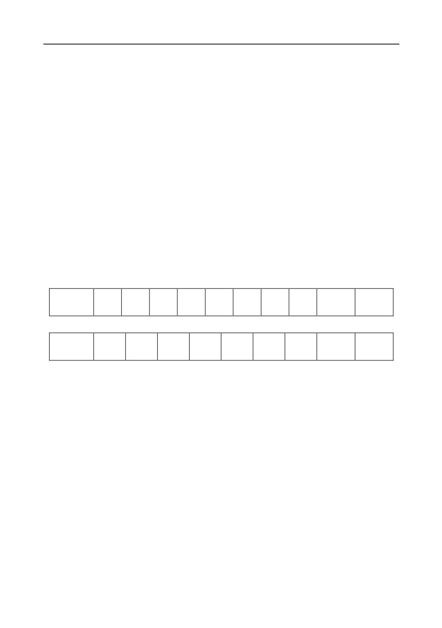
11-bit character frame (Bits 1 to 8 are data bits)
Check
Start bit
BIT1
BIT2
BIT3
BIT4
BIT5
BIT6
BIT7
BIT8
End bit
bit
10-bit character frame (Bits 1 to 7 are data bits)
Check
Start bit
BIT1
BIT2
BIT3
BIT4
BIT5
BIT6
BIT7
End bit
bit
In a character frame, only the data bits carry information. The start bit, check bit, and end bit are used
to facilitate the transmission of the data bits to the destination device. In practical applications, you
must set the data bits, parity check bits, and end bits consistently.
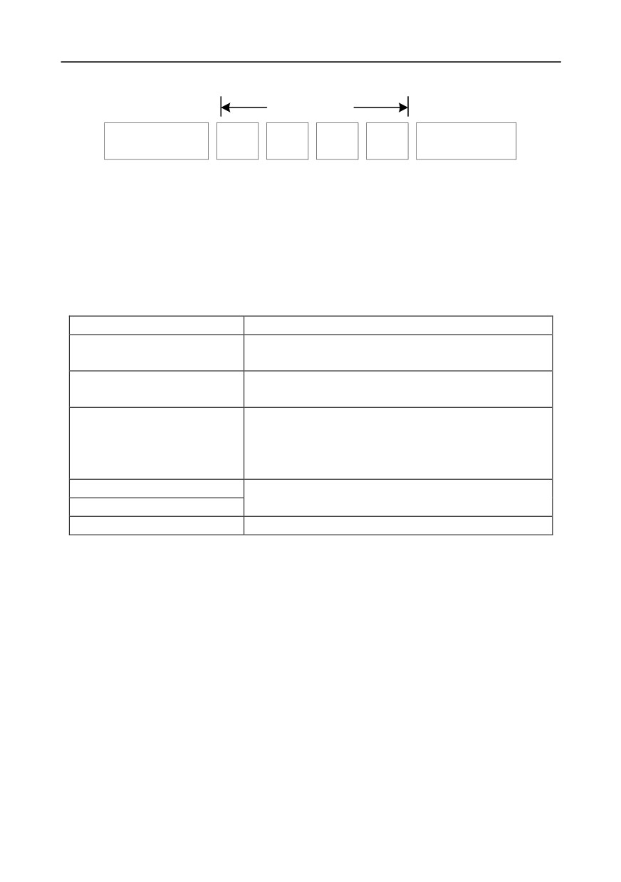
In RTU mode, the transmission of a new frame always starts from an idle time (the transmission time
of 3.5 bytes). On a network where the transmission rate is calculated based on the baud rate, the
transmission time of 3.5 bytes can be easily obtained. After the idle time ends, the data domains are
transmitted in the following sequence: slave address, operation command code, data, and CRC
check character. Each byte transmitted in each domain includes 2 hexadecimal characters (0-9, A-F).
The network devices always monitor the communication bus. After receiving the first domain (address
information), each network device identifies the byte. After the last byte is transmitted, a similar
transmission interval (the transmission time of 3.5 bytes) is used to indicate that the transmission of
the frame ends. Then, the transmission of a new frame starts.
-256-
Chapter 9
RTU data frame format
Modbus packet
Start with an idle time (at
End with an idle time (at
Slave
Function
least the transmission
Data
Check
least the transmission
address
code
time of 3.5 bytes)
time of 3.5 bytes)
The information of a frame must be transmitted in a continuous data flow. If there is an interval greater
than the transmission time of 1.5 bytes before the transmission of the entire frame is complete, the
receiving device deletes the incomplete information, and mistakes the subsequent byte for the
address domain of a new frame. Similarly, if the transmission interval between two frames is shorter
than the transmission time of 3.5 bytes, the receiving device mistakes it for the data of the last frame.
The CRC check value is incorrect due to the disorder of the frames, and thus a communication fault
occurs.
The following table describes the standard structure of an RTU frame.
START (frame header)
T1-T2-T3-T4 (transmission time of 3.5 bytes)
Communication address: 0-247 (decimal system) (0 is the
ADDR (slave address domain)
broadcast address)
03H: read slave parameters
CMD (function domain)
06H: write slave parameters
DATA (N-1)
Data of 2×N bytes, main content of the communication as well
DATA (0)
as the core of data exchanging
(data domain)
CRC CHK (LSBs)
Detection value: CRC (16 bits)
CRC CHK high bit (MSBs)
END (frame tail)
T1-T2-T3-T4 (transmission time of 3.5 bytes)
9.3.2.2 RTU communication frame error check modes
During the transmission of data, errors may occur due to various factors. Without check, the data
receiving device cannot identify data errors and may make a wrong response. The wrong response
may cause severe problems. Therefore, the data must be checked.
The check is implemented as follows: The transmitter calculates the to-be-transmitted data based on
a specific algorithm to obtain a result, adds the result to the rear of the message, and transmits them
together. After receiving the message, the receiver calculates the data based on the same algorithm
to obtain a result, and compares the result with that transmitted by the transmitter. If the results are
the same, the message is correct. Otherwise, the message is considered wrong.
The error check of a frame includes two parts, namely, bit check on individual bytes (that is, odd/even
check using the check bit in the character frame), and whole data check (CRC check).
Bit check on individual bytes (odd/even check)
You can select the bit check mode as required, or you can choose not to perform the check, which will
affect the check bit setting of each byte.
-257-
Chapter 9
Definition of even check: Before the data is transmitted, an even check bit is added to indicate
whether the number of "1" in the to-be-transmitted data is odd or even. If it is even, the check bit is set
to "0"; and if it is odd, the check bit is set to "1".
Definition of odd check: Before the data is transmitted, an odd check bit is added to indicate whether
the number of "1" in the to-be-transmitted data is odd or even. If it is odd, the check bit is set to "0";
and if it is even, the check bit is set to "1".
For example, the data bits to be transmitted are "11001110", including five "1". If the even check is
applied, the even check bit is set to "1"; and if the odd check is applied, the odd check bit is set to "0".
During the transmission of the data, the odd/even check bit is calculated and placed in the check bit of
the frame. The receiving device performs the odd/even check after receiving the data. If it finds that
the odd/even parity of the data is inconsistent with the preset information, it determines that a
communication error occurs.
CRC check mode
A frame in the RTU format includes an error detection domain based on the CRC calculation. The
CRC domain checks all the content of the frame. The CRC domain consists of two bytes, including 16
binary bits. It is calculated by the transmitter and added to the frame. The receiver calculates the CRC
of the received frame, and compares the result with the value in the received CRC domain. If the two
CRC values are not equal to each other, errors occur in the transmission.
During CRC, 0xFFFF is stored first, and then a process is invoked to process a minimum of 6
contiguous bytes in the frame based on the content in the current register. CRC is valid only for the
8-bit data in each character. It is invalid for the start, end, and check bits.
During the generation of the CRC values, the "exclusive or" (XOR) operation is performed on the
each 8-bit character and the content in the register. The result is placed in the bits from the least
significant bit (LSB) to the most significant bit (MSB), and 0 is placed in the MSB. Then, LSB is
detected. If LSB is 1, the XOR operation is performed on the current value in the register and the
preset value. If LSB is 0, no operation is performed. This process is repeated 8 times. After the last bit
(8th bit) is detected and processed, the XOR operation is performed on the next 8-bit byte and the
current content in the register. The final values in the register are the CRC values obtained after
operations are performed on all the bytes in the frame.
The calculation adopts the international standard CRC check rule. You can refer to the related
standard CRC algorithm to compile the CRC calculation program as required.
The following is a simple CRC calculation function for your reference (using the C programming
language):
unsigned int crc_cal_value(unsigned char×data_value,unsigned char data_length)
{
int i;
unsigned int crc_value=0xffff;
while(data_length--)
-258-
Chapter 9
{
crc_value^=×data_value++;
for(i=0;i<8;i++)
{
if(crc_value&0x0001)
crc_value=(crc_value>>1)^0xa001;
else
crc_value=crc_value>>1;
}
}
return(crc_value);
}
In the ladder logic, CKSM uses the table look-up method to calculate the CRC value according to the
content in the frame. The program of this method is simple, and the calculation is fast, but the ROM
space occupied is large. Use this program with caution in scenarios where there are space
occupation limits on programs.
9.4 RTU command code and communication data
9.4.1 Command code: 03H, reading N words (continuously reading a maximum of 16 words)
The command code 03H is used by the master to read data from the inverter. The quantity of data to
be read depends on the "data quantity" in the command. A maximum of 16 pieces of data can be read.
The addresses of the read parameters must be contiguous. Each piece of data occupies 2 bytes, that
is, one word. The command format is presented using the hexadecimal system (a number followed by
"H" indicates a hexadecimal value). One hexadecimal value occupies one byte.
The 03H command is used to read information including the parameters and operation state of the
inverter.
For example, starting from the data address of 0004H, to read two contiguous pieces of data (that is,
to read content from the data addresses 0004H and 0005H), the structure of the frame is described in
the following table.
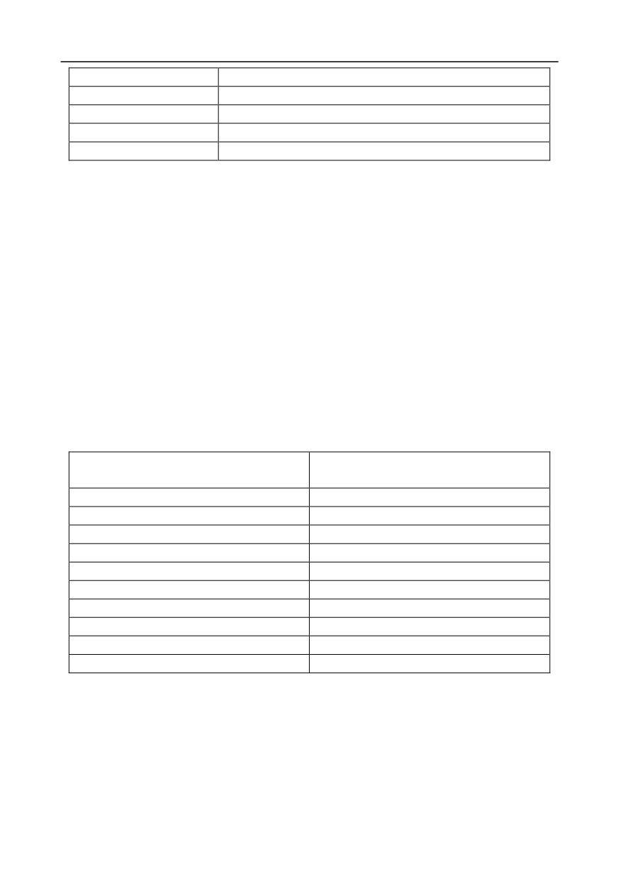
RTU master command (transmitted by the master to the inverter)
START
T1-T2-T3-T4 (transmission time of 3.5 bytes)
ADDR (address)
01H
CMD (command code)
03H
Most significant byte (MSB) of
00H
the start address
Least significant byte (LSB) of
04H
the start address
-259-
Chapter 9
MSB of data quantity
00H
LSB of data quantity
02H
LSB of CRC
85H
MSB of CRC
CAH
END
T1-T2-T3-T4 (transmission time of 3.5 bytes)
The value in START and END is "T1-T2-T3-T4 (transmission time of 3.5 bytes)", indicating that the
RS485 needs to stay idle for at least the transmission time of 3.5 bytes. An idle time is required to
distinguish on message from another to ensure that the two messages are not regarded as one.
The value of ADDR is 01H, indicating that the command is transmitted to the inverter whose address
is 01H. The ADDR information occupies one byte.
The value of CMD is 03H, indicating that the command is used to read data from the inverter. The
CMD information occupies one byte.
"Start address" indicates that data reading is started from this address. It occupies two bytes, with the
MSB on the left and LSB on the right.
"Data quantity" indicates the quantity of data to be read (unit: word).
The value of "Start address" is 0004H, and that of "Data quantity" is 0002H, indicating that data is to
be read from the data addresses of 0004H and 0005H.
CRC check occupies two bytes, with the LSB on the left, and MSB on the right.
RTU slave response (transmitted by the inverter to the master)
T1-T2-T3-T4 (transmission time of 3.5
START
bytes)
ADDR
01H
CMD
03H
Number of bytes
04H
MSB of data in 0004H
13H
LSB of data in 0004H
88H
MSB of data in 0005H
00H
LSB of data in 0005H
00H
LSB of CRC
7EH
MSB of CRC
9DH
END
T1-T2-T3-T4 (transmission time of 3.5 bytes)
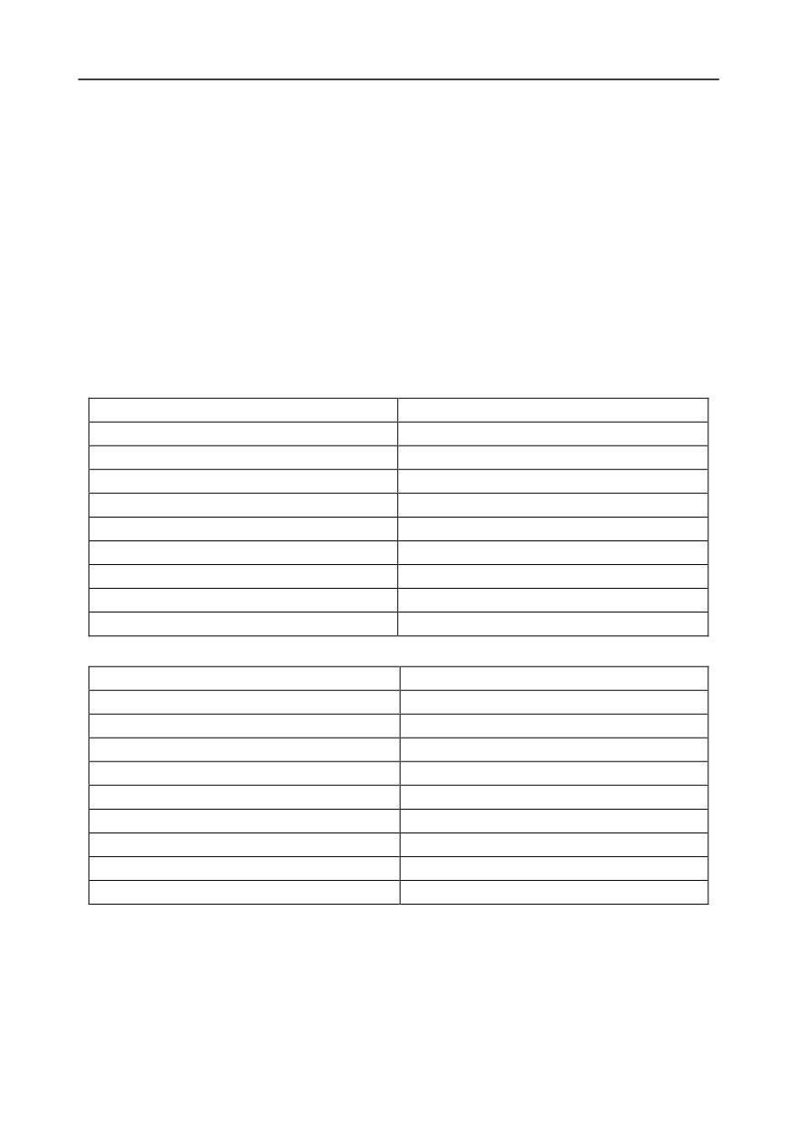
The definition of the response information is described as follows:
The value of ADDR is 01H, indicating that the message is transmitted by the inverter whose address
is 01H. The ADDR information occupies one byte.
The value of CMD is 03H, indicating that the message is a response of the inverter to the 03H
command of the master for reading data. The CMD information occupies one byte.
"Number of bytes" indicates the number of bytes between a byte (not included) and the CRC byte (not
-260-
Chapter 9
included). The value 04 indicates that there are four bytes of data between "Number of bytes" and
"LSB of CRC", that is, "MSB of data in 0004H", "LSB of data in 0004H", "MSB of data in 0005H", and
"LSB of data in 0005H".
A piece of data is two bytes, with the MSB on the left and LSB on the right. From the response, we
can see that the data in 0004H is 1388H, and that in 0005H is 0000H.
CRC check occupies two bytes, with the LSB on the left, and MSB on the right.
9.4.2 Command code: 06H, writing a word
This command is used by the master to write data to the inverter. One command can be used to write
only one piece of data. It is used to modify the parameters and operation mode of the inverter.
For example, to write 5000 (1388H) to 0004H of the inverter whose address is 02H, the structure of
the frame is described in the following table.
RTU master command (transmitted by the master to the inverter)
START
T1-T2-T3-T4 (transmission time of 3.5 bytes)
ADDR
02H
CMD
06H
MSB of data writing address
00H
LSB of data writing address
04H
MSB of to-be-written data
13H
LSB of to-be-written data
88H
LSB of CRC
C5H
MSB of CRC
6EH
END
T1-T2-T3-T4 (transmission time of 3.5 bytes)
RTU slave response (transmitted by the inverter to the master)
START
T1-T2-T3-T4 (transmission time of 3.5 bytes)
ADDR
02H
CMD
06H
MSB of data writing address
00H
LSB of data writing address
04H
MSB of to-be-written data
13H
LSB of to-be-written data
88H
LSB of CRC
C5H
MSB of CRC
6EH
END
T1-T2-T3-T4 (transmission time of 3.5 bytes)
Note: The sections 9.2 and 9.3 mainly describes the command formats. For the detailed application,
see the examples in section 9.4.8.
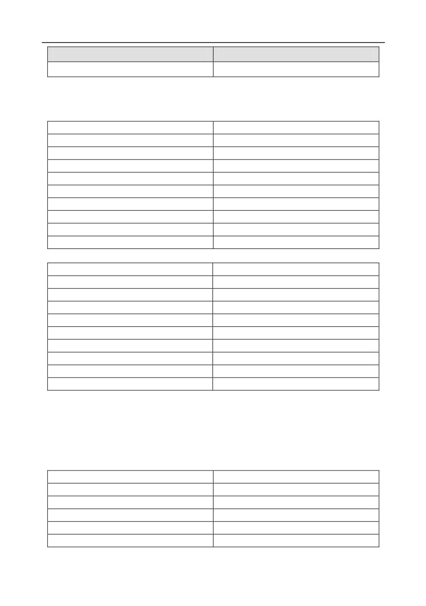
9.4.3 Command code: 08H, diagnosis
Sub-function code description
-261-
Chapter 9
Sub-function code
Description
0000
Return data based on query requests
For example, to query about the circuit detection information about the inverter whose address is 01H,
the query and return strings are the same, and the format is described in the following tables.
RTU master command
START
T1-T2-T3-T4 (transmission time of 3.5 bytes)
ADDR
01H
CMD
08H
MSB of the sub-function code
00H
LSB of the sub-function code
00H
MSB of data
12H
LSB of data
ABH
LSB of CRC CHK
ADH
MSB of CRC CHK
14H
END
T1-T2-T3-T4 (transmission time of 3.5 bytes)
RTU slave response
START
T1-T2-T3-T4 (transmission time of 3.5 bytes)
ADDR
01H
CMD
08H
MSB of the sub-function code
00H
LSB of the sub-function code
00H
MSB of data
12H
LSB of data
ABH
LSB of CRC CHK
ADH
MSB of CRC CHK
14H
END
T1-T2-T3-T4 (transmission time of 3.5 bytes)
9.4.4 Command code: 10H, continuous writing
The command code 10H is used by the master to write data to the inverter. The quantity of data to be
written is determined by "Data quantity", and a maximum of 16 pieces of data can be written.
For example, to write 5000 (1388H) and 50 (0032H) respectively to 0004H and 0005H of the inverter
whose slave address is 02H, the structure of the frame is described in the following table.
RTU master command (transmitted by the master to the inverter)
START
T1-T2-T3-T4 (transmission time of 3.5 bytes)
ADDR
02H
CMD
10H
MSB of data writing address
00H
LSB of data writing address
04H
MSB of data quantity
00H
-262-
Chapter 9
LSB of data quantity
02H
Number of bytes
04H
MSB of data to be written to 0004H
13H
LSB of data to be written to 0004H
88H
MSB of data to be written to 0005H
00H
LSB of data to be written to 0005H
32H
LSB of CRC
C5H
MSB of CRC
6EH
END
T1-T2-T3-T4 (transmission time of 3.5 bytes)
RTU slave response (transmitted by the inverter to the master)
START
T1-T2-T3-T4 (transmission time of 3.5 bytes)
ADDR
02H
CMD
10H
MSB of data writing address
00H
LSB of data writing address
04H
MSB of data quantity
00H
LSB of data quantity
02H
LSB of CRC
C5H
MSB of CRC
6EH
END
T1-T2-T3-T4 (transmission time of 3.5 bytes)
9.4.5 Data address definition
This section describes the address definition of communication data. The addresses are used for
controlling the running, obtaining the state information, and setting related function parameters of the
inverter.
9.4.5.1 Function code address representation rules
The address of a function code consists of two bytes, with the MSB on the left and LSB on the right.
The MSB ranges from 00 to ffH, and the LSB also ranges from 00 to ffH. The MSB is the hexadecimal
form of the group number before the dot mark, and LSB is that of the number behind the dot mark.
Take P05.06 as an example, the group number is 05, that is, the MSB of the parameter address is the
hexadecimal form of 05; and the number behind the dot mark is 06, that is, the LSB is the
hexadecimal form of 06. Therefore, the function code address is 0506H in the hexadecimal form. For
P10.01, the parameter address is 0A01H.
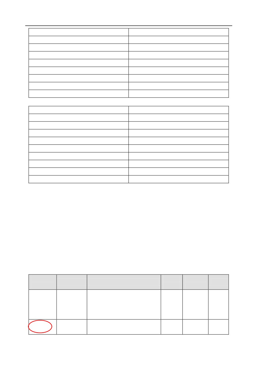
Function
Setting
Default
Name
Detailed parameter description
Modify
code
range
value
0: Stop after running once
Simple PLC
1: Keep running in the final value
P10.00
0-2
0
○
mode
after running once
2: Cyclic running
P10.01
Simple PLC
0: No memory after power down
0-1
0
○
memory
1: Memory after power down
-263-
Chapter 9
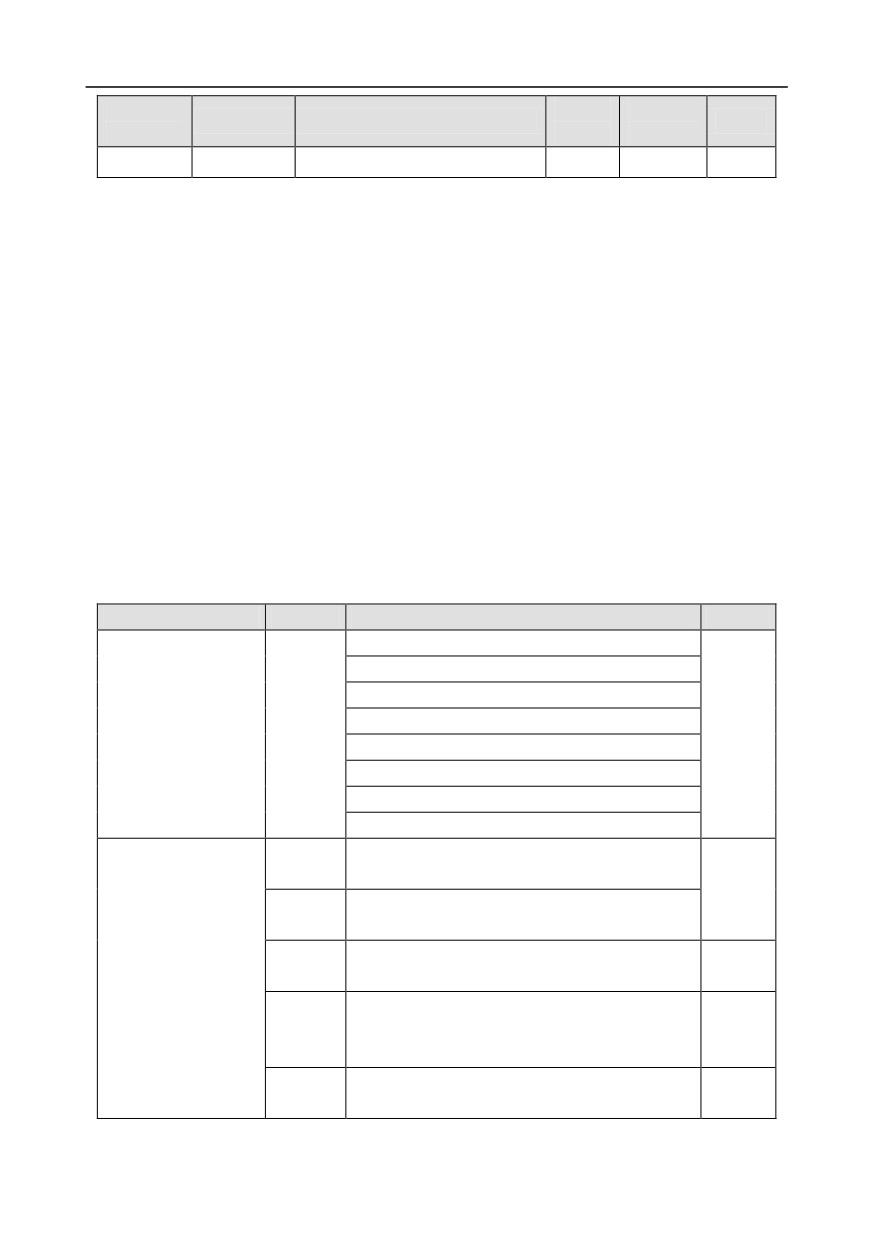
Function
Setting
Default
Name
Detailed parameter description
Modify
code
range
value
selection
Note:
1. The parameters in the P99 group are set by the manufacturer. They cannot be read or modified.
Some parameters cannot be modified when the inverter is running; some cannot be modified
regardless of the state of the inverter. Pay attention to the setting range, unit, and related
description of a parameter when modifying it.
2. The service life of the Electrically Erasable Programmable Read-Only Memory (EEPROM) may
be reduced if it is frequently used for storage. For users, some function codes do not need to be
stored during communication. The application requirements can be met by modifying the value of
the on-chip RAM, that is, modifying the MSB of the corresponding function code address from 0
to 1. For example, if P00.07 is not to be stored in the EEPROM, you need only to modify the
value of the RAM, that is, set the address to 8007H. The address can be used only for writing
data to the on-chip RAM, and it is invalid when used for reading data.
9.4.5.2 Description of other function code addresses
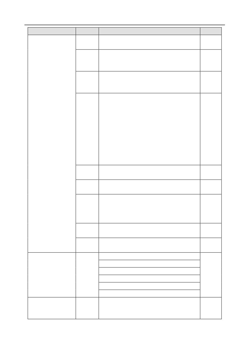
In addition to modifying the parameters of the inverter, the master can also control the inverter, such
as start and stop it, and monitor the operation state of the inverter. The following table describes other
function parameters.
Function
Address
Data description
R/W
0001H: Forward running
0002H: Reverse running
0003H: Forward jogging
Communication-based
0004H: Reverse jogging
2000H
R/W
control command
0005H: Stop
0006H: Coast to stop (emergency stop)
0007H: Fault reset
0008H: Jogging to stop
Communication-based frequency setting
(0-
2001H
Fmax, unit: 0.01 Hz)
R/W
PID setting, range (0-1000, 1000 corresponding
2002H
to 100.0%)
PID feedback,
range
(0-1000,
1000
Communication-based
2003H
R/W
corresponding to 100.0%)
value setting
Torque
setting
(-3000-+3000,
1000
2004H
corresponding to 100.0% of the rated current of
R/W
the motor)
Setting of the upper limit of the forward running
2005H
R/W
frequency (0-Fmax, unit: 0.01 Hz)
-264-
Chapter 9
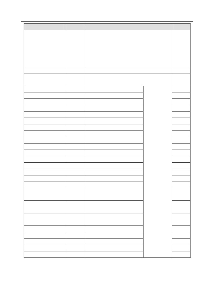
Function
Address
Data description
R/W
Setting of the upper limit of the reverse running
2006H
R/W
frequency (0-Fmax, unit: 0.01 Hz)
Upper limit of the electromotion torque (0-3000,
2007H
1000 corresponding to
100.0% of the rated
R/W
current of the inverter)
Upper limit of the brake torque (0-3000, 1000
2008H
corresponding to 100.0% of the rated current of
R/W
the motor)
Special control command word:
Bit0-1: =00: Motor 1
=01: Motor 2
=10: Motor 3
=11: Motor 4
Bit2:
=1 Torque control disabled
=0: Torque
control cannot be disabled
2009H
R/W
Bit3: =1 Power consumption reset to 0
=0: Power consumption not reset
Bit4:
=1 Pre-excitation
=0: Pre-excitation
disabled
Bit5: =1 DC brake
=0: DC brake disabled
Virtual input terminal command, range: 0x000-
200AH
R/W
0x1FF
Virtual output terminal command, range: 0x00-
200BH
R/W
0x0F
Voltage setting
(used when V/F separation is
implemented)
200CH
R/W
(0-1000, 1000 corresponding to 100.0% of the
rated voltage of the motor)
AO output setting
1
(-1000-+1000,
1000
200DH
R/W
corresponding to 100.0%)
AO output setting
2
(-1000-+1000,
1000
200EH
R/W
corresponding to 100.0%)
0001H: Forward running
0002H: Reverse running
0003H: Stopped
Inverter state word 1
2100H
R
0004H: Faulty
0005H: POFF
0006H: Pre-excited
Bit0:
=0: Not ready to run =1: Ready to run
Inverter state word 2
2101H
Bi1-2: =00: Motor 1
=01: Motor 2
R
=10: Motor 3
=11: Motor 4
-265-
Chapter 9
Function
Address
Data description
R/W
Bit3:
=0: Asynchronous machine
=1:
Synchronous machine
Bit4: =0: No overload alarm =1: Overload alarm
Bit5-Bit6:
=00: Keypad-based control
=01:
Terminal-based control
=10: Communication-based control
Inverter fault code
2102H
See the description of fault types.
R
Inverter identification
2103H
GD35-----0x0109
R
code
Running frequency
3000H
0-Fmax (unit: 0.01Hz)
R
Set frequency
3001H
0-Fmax (unit: 0.01Hz)
R
Bus voltage
3002H
0.0-2000.0 V (unit: 0.1V)
R
Output voltage
3003H
0-1200V (unit: 1V)
R
Output current
3004H
0.0-3000.0A (unit: 0.1A)
R
Rotating speed
3005H
0-65535 (unit: 1RPM)
R
Ouptut power
3006H
-300.0-+300.0% (unit: 0.1%)
R
Output torque
3007H
-250.0-+250.0% (unit: 0.1%)
R
Closed-loop setting
3008H
-100.0-+100.0% (unit: 0.1%)
R
Closed-loop feedback
3009H
-100.0-+100.0% (unit: 0.1%)
R
Input state
300AH
000-1FF
R
Output state
300BH
000-1FF
Compatible
R
Analog input 1
300CH
0.00-10.00V (unit: 0.01V)
with CHF100A
R
Analog input 2
300DH
0.00-10.00V (unit: 0.01V)
and CHV100
R
Analog input 3
300EH
-10.00-10.00V (unit: 0.01V)
communication
R
Analog input 4
300FH
addresses
R
Read input of
3010H
0.00-50.00kHz (unit: 0.01Hz)
R
high-speed pulse 1
Read input of
3011H
R
high-speed pulse 2
Read current step of
3012H
0-15
R
multi-step speed
External length
3013H
0-65535
R
External count value
3014H
0-65535
R
Torque setting
3015H
-300.0-+300.0% (unit: 0.1%)
R
Identification code
3016H
R
Fault code
5000H
R
The Read/Write (R/W) characteristics indicate whether a function can be read and written. For
example, "Communication-based control command" can be written, and therefore the command code
6H is used to control the inverter. The R characteristic indicates that a function can only be read, and
-266-
Chapter 9
W indicates that a function can only be written.
Note: Some parameters in the preceding table are valid only after they are enabled. Take the running
and stop operations as examples, you need to set "Running command channel" (P00.01) to
"Communication", and set "Communication running command channel" (P00.02) to the Modbus
communication channel. For another example, when modifying "PID setting", you need to set "PID
reference source" (P09.00) to Modbus communication.
The following table describes the encoding rules of device codes (corresponding to the identification
code 2103H of the inverter).
8 MSBs
Meaning
8 LSBs
Meaning
0x08
GD35 vector inverter
0x09
GD35-H1 vector inverter
01
GD
0x0a
GD300 vector inverter
0xa0
GD350 vector inverter
9.4.6 Fieldbus scale
In practical applications, communication data is represented in the hexadecimal form, but
hexadecimal values cannot represent decimals. For example, 50.12 Hz cannot be represented in the
hexadecimal form. In such cases, we can multiply 50.12 by 100 to obtain an integer 5012, and then
50.12 can be represented as 1394H (5012 in the decimal form) in the hexadecimal form.
In the process of multiplying a non-integer by a multiple to obtain an integer, the multiple is referred to
as a fieldbus scale.
The fieldbus scale depends on the number of decimals in the value specified in "Detailed parameter
description" or "Default value". If there are n decimals in the value, the fieldbus scale m is the
nth-power of 10. Take the following table as an example, m is 10.
Function
Default
Name
Detailed parameter description
code
value
P01.20
Wake-up-from-sleep delay
0.0-3600.0s (valid when P01.19 is 2)
0.0s
0: Restart is disabled
P01.21
Restart after power cut
0
1: Restart is enabled
The value specified in "Detailed parameter description" or "Default value" contains one decimal, so
the fieldbus scale is
10. If the value received by the upper computer is
50, the value of
"Wake-up-from-sleep delay" of the inverter is 5.0 (5.0=50/10).
To set the "Wake-up-from-sleep delay" to 5.0s through Modbus communication, you need first to
multiply 5.0 by 10 according to the scale to obtain an integer 50, that is, 32H in the hexadecimal form,
and then transmit the following write command:
01
06
01 14
00 32
49 E7
Inverter
Write
Parameter Parameter
CRC
address command address
data
-267-
Chapter 9
After receiving the command, the inverter converts 50 into 5.0 based on the fieldbus scale, and then
sets "Wake-up-from-sleep delay" to 5.0s.
For another example, after the upper computer transmits the "Wake-up-from-sleep delay" parameter
read command, the master receives the following response from the inverter:
01
03
02
00 32
39 91
Inverter
Read
2-byte
Parameter
CRC
address command
data
data
The parameter data is 0032H, that is, 50, so 5.0 is obtained based on the fieldbus scale (50/10=5.0).
In this case, the master identifies that the "Wake-up-from-sleep delay" is 5.0s.
9.4.7 Error message response
Operation errors may occur in communication-based control. For example, some parameters can
only be read, but a write command is transmitted. In this case, the inverter returns an error message
response.
Error message responses are transmitted by the inverter to the master. The following table describes
the codes and definitions of the error message responses.
Code
Name
Definition
The command code received by the upper computer is not allowed
to be executed. The possible causes are as follows:
Invalid
01H
• The function code is applicable only on new devices and is not
command
implemented on this device.
• The slave is in the faulty state when processing this request.
For the inverter, the data address in the request of the upper
Invalid data
computer is not allowed. In particular, the combination of the
02H
address
register address and the number of the to-be-transmitted bytes is
invalid.
The received data domain contains a value that is not allowed. The
value indicates the error of the remaining structure in the combined
03H
Invalid data bit
request.
Note: It does not mean that the data item submitted for storage in
the register includes a value unexpected by the program.
Operation
The parameter is set to an invalid value in the write operation. For
04H
failure
example, a function input terminal cannot be set repeatedly.
Password
The password entered in the password verification address is
05H
error
different from that set in P03.00.
The length of the data frame transmitted by the upper computer is
Data frame
06H
incorrect, or in the RTU format, the value of the CRC check bit is
error
inconsistent with the CRC value calculated by the lower computer
-268-

Chapter 9
Code
Name
Definition
Parameter
The parameter to be modified in the write operation of the upper
07H
read-only
computer is a read-only parameter.
Parameter
cannot be
The parameter to be modified in the write operation of the upper
08H
modified in
computer cannot be modified during the running of the inverter.
running
A user password is set, and the upper computer does not provide
Password
09H
the password to unlock the system when performing a read or write
protection
operation. The error of "system locked" is reported.
When returning a response, the device uses a function code domain and fault address to indicate
whether it is a normal response (no error) or exception response (some errors occur). In a normal
response, the device returns the corresponding function code and data address or sub-function code.
In an exception response, the device returns a code that is equal to a normal code, but the first bit is
logic 1.
For example, if the master device transmits a request message to a slave device for reading a group
of function code address data, the code is generated as follows:
0 0 0 0 0 0 1 1 (03H in the hexadecimal form)
For a normal response, the same code is returned.
For an exception response, the following code is returned:
1 0 0 0 0 0 1 1 (83H in the hexadecimal form)
In addition to the modification of the code, the slave returns a byte of exception code that describes
the cause of the exception. After receiving the exception response, the typical processing of the
master device is to transmit the request message again or modify the command based on the fault
information.
For example, to set the "Running command channel" (P00.01, the parameter address is 0001H) of
the inverter whose address is 01H to 03, the command is as follows:
01
06
00 01
00 03
98 0B
Inverter
Write
Parameter
Parameter
CRC
address command
address
data
But the setting range of the "Running command channel" is 0 to 2. The value 3 exceeds the setting
range. In this case, the inverter returns an error message response as shown in the following:
01
86
04
43 A3
Inverter
Exception
Error code
CRC
address
response code
The exception response code 86H (generated based on the MSB "1" of the write command 06H)
-269-
Chapter 9
indicates that it is an exception response to the write command (06H). The error code is 04H. From
the preceding table, we can see that it indicates the error "Operation failure", which means "The
parameter is set to an invalid value in the write operation".
9.4.8 Read/Write operation example
For the formats of the read and write commands, see sections 9.4.1 and 9.4.2.
9.4.8.1 Read command 03H examples
Example 1: Read state word 1 of the inverter whose address is 01H. From the table of other function
parameters, we can see that the parameter address of state word 1 of the inverter is 2100H.
The read command transmitted to the inverter is as follows:
01
03
21 00
00 01
8E 36
Inverter
Read
Parameter
Data quantity
CRC
address
command
address
Assume that the following response is returned:
01
03
02
00 03
F8 45
Inverter
Read
Number
CRC
Data content
address
command
of bytes
The data content returned by the inverter is 0003H, which indicates that the inverter is in the stopped
state.
Example 2: View information about the inverter whose address is 03H, including "Type of current
fault" (P07.27) to "Type of last but four fault" (P07.32) of which the parameter addresses are 071BH to
0720H (contiguous 6 parameter addresses starting from 071BH).
The command transmitted to the inverter is as follows:
03
03
07 1B
00 06
B5 59
Inverter
Read
Start
6 parameters in total
CRC
address
command address
Assume that the following response is returned:
03 03 0C 00 23 00 23 00 23 00 23 00 23 00 23 5F D2
Inverter
Read Number of
Type of
Type of
Type of last
Type of last
Type of last
Type of last
CRC
address command bytes
current fault
last fault
but one fault
but two fault
but three fault
but four fault
From the returned data, we can see that all the fault types are 0023H, that is, 35 in the decimal form,
which means the maladjustment fault (STo)
9.4.8.2 Write command 06H examples
Example 1: Set the inverter whose address is 03H to be forward running. Refer to the table of other
function parameters, the address of "Communication-based control command" is 2000H, and 0001H
indicates forward running, as shown in the following figure.
-270-
Chapter 9
Function
Address
Data description
R/W
0001H: Forward running
0002H: Reverse running
0003H: Forward jogging
Communication-based
0004H: Reverse jogging
2000H
R/W
control command
0005H: Stop
0006H: Coast to stop (emergency stop)
0007H: Fault reset
0008H: Jogging to stop
The command transmitted by the master is as follows:
03
06
20 00
00 01
42 28
Inverter
Write
Parameter
Forward
CRC
address
command
address
running
If the operation is successful, the following response is returned (same as the command transmitted
by the master):
03
06
20 00
00 01
42 28
Inverter
Write
Parameter
Forward
CRC
address
command
address
running
Example 2: Set the "Max. output frequency" of the inverter whose address is 03H to 100 Hz.
Function
Default
Modi
Name
Detailed parameter description
code
value
fy
Used to set the max. output frequency of the
Max. output
inverter. It is the basis of frequency setup and the
P00.03
50.00Hz
◎
frequency
acceleration/deceleration.
Setting range: Max (P00.04, 10.00) -630.00Hz
From the number of decimals, we can see that the fieldbus scale of the "Max. output frequency"
(P00.03) is 100. Multiply 100 Hz by 100. The value 10000 is obtained, and it is 2710H in the
hexadecimal form.
The command transmitted by the master is as follows:
03
06
00 03
27 10
62 14
Inverter
Write
Parameter
Parameter
CRC
address
command
address
data
If the operation is successful, the following response is returned (same as the command transmitted
by the master):
-271-
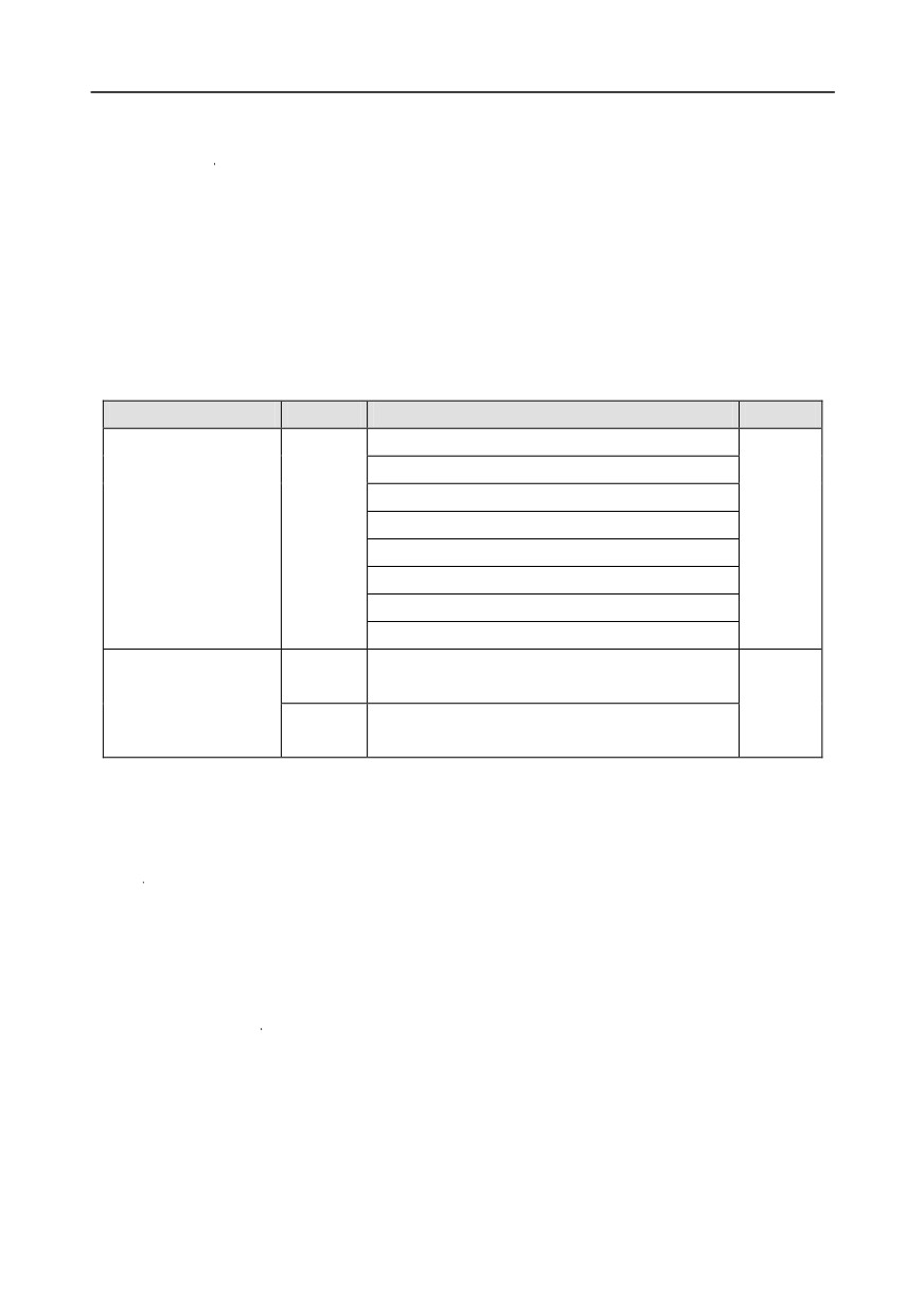
Chapter 9
03
06
00 03
27 10
62 14
Inverter
Write
Parameter
Parameter
CRC
address
command
address
data
Note: In the preceding command description, spaces are added to a command just for explanatory
purposes. In practical applications, no space is required in the commands.
9.4.8.3 Continuously write command 10H examples
Example 1: Set the inverter whose address is 01H to be forward running at the frequency of 10 Hz.
Refer to the table of other function parameters, the address of "Communication-based control
command" is 2000H, 0001H indicates forward running, and the address of "Communication-based
value setting" is 2001H, as shown in the following figure. 10 Hz is 03E8H in the hexadecimal form.
Function
Address
Data description
R/W
0001H: Forward running
0002H: Reverse running
0003H: Forward jogging
Communication-based
0004H: Reverse jogging
2000H
R/W
control command
0005H: Stop
0006H: Coast to stop (emergency stop)
0007H: Fault reset
0008H: Jogging to stop
Communication-based frequency setting
(0-
2001H
Communication-based
Fmax, unit: 0.01 Hz)
R/W
value setting
PID setting, range (0-1000, 1000 corresponding
2002H
to 100.0%)
In the actual operation, set P00.01 to 2 and P00.06 to 8.
The command transmitted by the master is as follows:
01
10
20 00
00 02
04
00 01
03 E8
3B 10
Inverter
Continuous
Parameter
Parameter
Number of
Froward
10 Hz
CRC
address
write
address
quantity
bytes
running
command
If the operation is successful, the following response is returned:
01
10
20 00
00 02
4A 08
Inverter
Continuous
Parameter
Parameter
CRC
address
write
address
quantity
command
Example 2: Set "Acceleration time" of the inverter whose address is 01H to 10s, and "Deceleration
time" to 20s.
-272-
Chapter 9
Function
Default
Modi
Name
Detailed parameter description
code
value
fy
Acceleration
Acceleration time is the time needed for accelerating
Depend
P00.11
○
time 1
from 0Hz to max. output frequency (P00.03).
on model
Deceleration time is the time needed from
decelerating from max. output frequency (P00.03) to
0Hz.
Goodrive350 series inverter defines four groups of
Deceleration
Depend
P00.12
acceleration and deceleration time, which can be
○
time 1
on model
selected via multi-function digital input terminals
(P05 group). The acceleration/deceleration time of
the inverter is the first group by default.
Setting range of P00.11 and P00.12: 0.0-3600.0s
The address of P00.11 is 000B, 10s is 0064H in the hexadecimal form, and 20s is 00C8H in the
hexadecimal form.
The command transmitted by the master is as follows:
01
10
00 0B
00 02
04
00 64
00 C8
F2 55
Inverter
Continuous
Parameter
Parameter
Number of
10s
20s
CRC
address
write
address
quantity
bytes
command
If the operation is successful, the following response is returned:
01
10
00 0B
00 02
30 0A
Inverter
Continuous
Parameter
Parameter
CRC
address
write
address
quantity
command
Note: In the preceding command description, spaces are added to a command just for explanatory
purposes. In practical applications, no space is required in the commands.
9.4.8.4 Modbus communication commissioning example
A PC is used as the host, an RS232-RS485 converter is used for signal conversion, and the PC serial
port used by the converter is COM1 (an RS232 port). The upper computer commissioning software is
the serial port commissioning assistant Commix, which can be downloaded from the Internet.
Download a version that can automatically execute the CRC check function. The following figure
shows the interface of Commix.
-273-
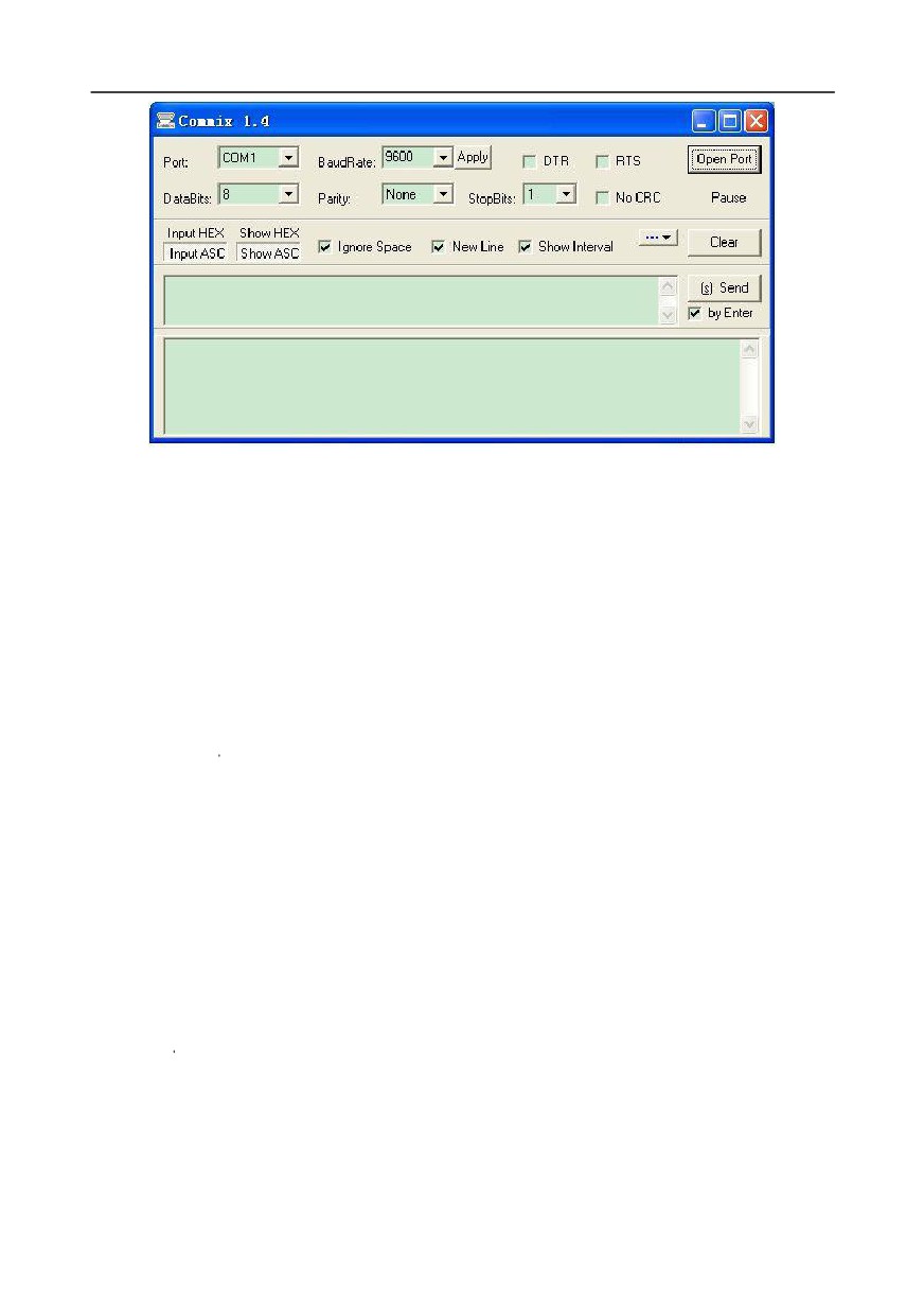
Chapter 9
First, set the serial port to COM1. Then, set the baud rate consistently with P14.01. The data bits,
check bits, and end bits must be set consistently with P14.02. If the RTU mode is selected, you need
to select the hexadecimal form Input HEX. To set the software to automatically execute the CRC
function, you need to select ModbusRTU, select CRC16 (MODBU SRTU), and set the start byte to 1.
After the auto CRC check function is enabled, do not enter CRC information in commands. Otherwise,
command errors may occur due to repeated CRC check.
The commissioning command to set the inverter whose address is 03H to be forward running is as
follows:
03
06
20 00
00 01
42 28
Inverter
Write
Parameter
Forward running
CRC
address command
address
Note:
1. Set the address (P14.00) of the inverter to 03.
2. Set "Channel of running commands" (P00.01) to "Communication", and set "Communication
channel of running commands" (P00.02) to the Modbus communication channel.
3. Click Send. If the line configuration and settings are correct, a response transmitted by the
inverter is received as follows:
03
06
20 00
00 01
42 28
Inverter
Write
Parameter
Forward running
CRC
address command
address
9.5 Common communication faults
Common communication faults include the following:
•
No response is returned.
-274-