Goodrive350 Series High-performance Multi-function Inver ter. Operation manual - page 6
Chapter 6
Function
Default
Modi
Name
Detailed parameter description
code
value
fy
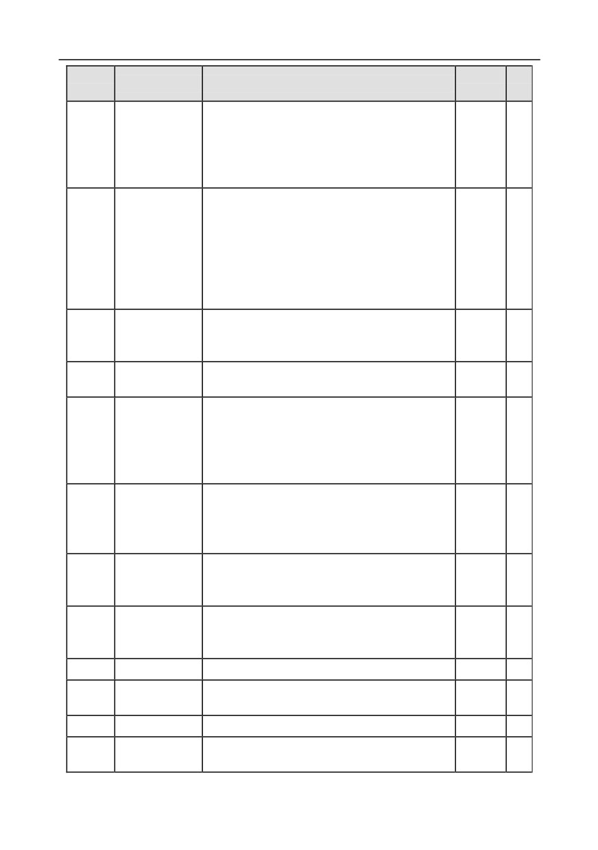
Display current motor power; 100% relative to rated
motor power, positive value is motoring state,
P17.08
Motor power
negative value is generating state.
0.0%
●
Range:
-300.0-300.0%
(relative to rated motor
power)
Display current output torque of the inverter; 100%
relative to rated motor torque, during forward
running, positive value is motoring state, negative
Motor output
P17.09
value is generating state, during reverse running,
0.0%
●
torque
positive value is generating state, negative value is
motoring state.
Range: -250.0-250.0%
The estimated motor rotor frequency under
Estimated motor
P17.10
open-loop vector condition.
0.00Hz
●
frequency
Range: 0.00- P00.03
Display current DC bus voltage of the inverter.
P17.11
DC bus voltage
0V
●
Range: 0.0-2000.0V
Display current digital input terminal state of the
inverter.
Digital input
P17.12
0000-03F
0
●
terminal state
Corresponds to HDIB, HDIA, S4, S3, S2 and S1
respectively
Display current digital output terminal state of the
Digital output
inverter.
P17.13
0
●
terminal state
0000-000F
Corresponds to R02, RO1, HDO and Y1 respectively
Digital
Display the regulating variable by UP/DOWN
P17.14
adjustment
terminals of the inverter.
0.00Hz
●
variable
Range: 0.00Hz-P00.03
Relative to percentage of the rated torque of current
Torque reference
P17.15
motor, display torque reference.
0.0%
●
value
Range: -300.0%-300.0% (rated motor current)
P17.16
Linear speed
0-65535
0
●
Reserved
P17.17
0-65535
0
●
variables
P17.18
Count value
0-65535
0
●
Display input signal of AI 1
P17.19
AI1 input voltage
0.00V
●
Range: 0.00-10.00V
-195-
Chapter 6
Function
Default
Modi
Name
Detailed parameter description
code
value
fy
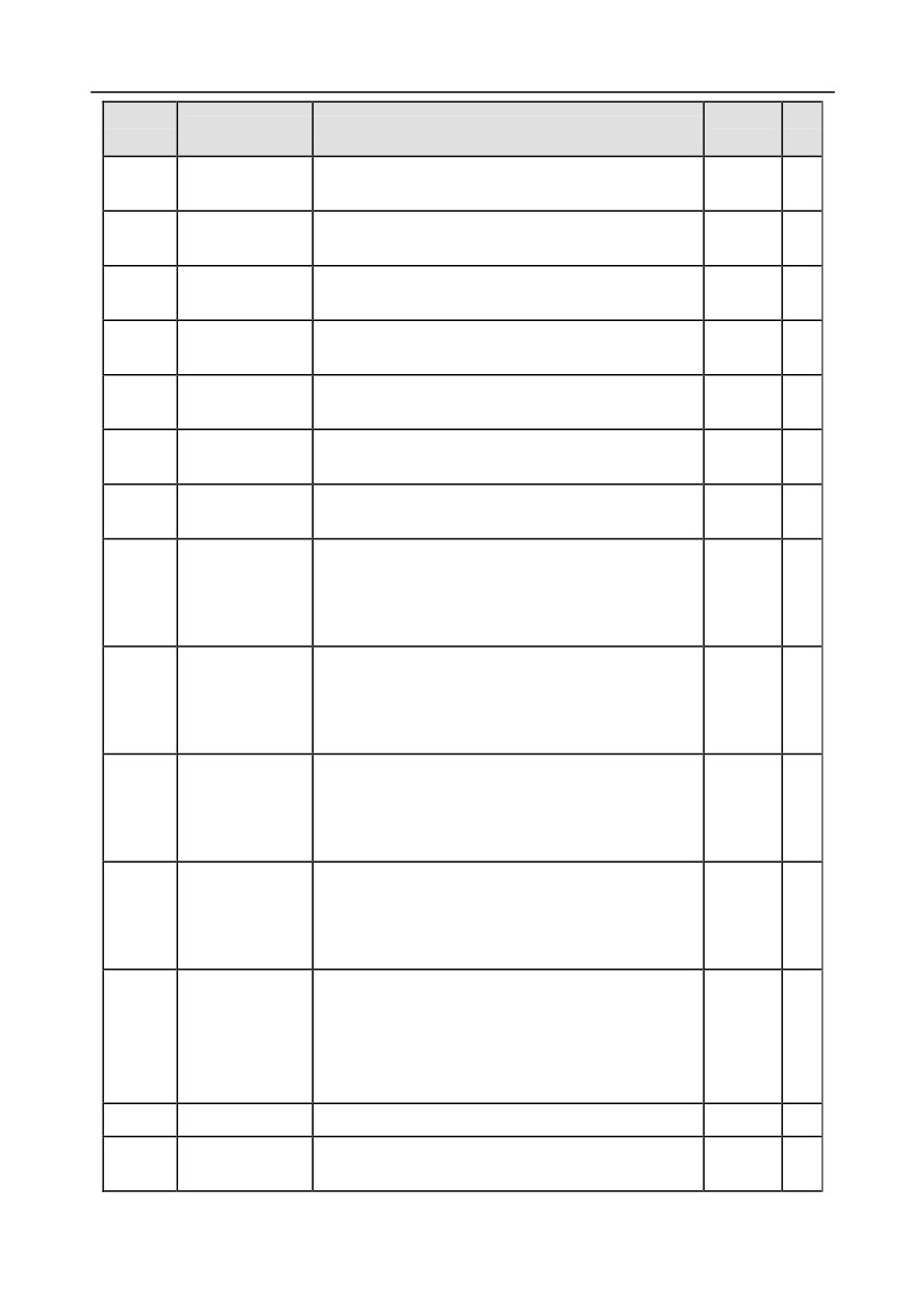
Display input signal of AI2
P17.20
AI2 input voltage
0.00V
●
Range: -10.00V-10.00V
HDIA input
Display input frequency of HDIA
0.000
P17.21
●
frequency
Range: 0.000-50.000kHz
kHz
HDIB input
Display input frequency of HDIB
0.000
P17.22
●
frequency
Range: 0.000-50.000kHz
kHz
PID reference
Display PID reference value
P17.23
0.0%
●
value
Range: -100.0-100.0%
PID feedback
Display PID feedback value
P17.24
0.0%
●
value
Range: -100.0-100.0%
Motor power
Display the power factor of current motor.
P17.25
1.00
●
factor
Range: -1.00-1.00
Current running
Display current running time of the inverter.
P17.26
0m
●
time
Range: 0-65535min
Simple PLC and
Display simple PLC and current step number
of
current step
P17.27
multi-step speed
0
●
number of
Range: 0-15
multi-step speed
Display the speed loop ASR controller output value
Motor ASR
under vector control mode, relative to the percentage
P17.28
0.0%
●
controller output
of rated torque of the motor.
Range: -300.0%-300.0% (rated motor current)
Pole angle of
Display initial identification angle of synchronous
open-loop
P17.29
motor
0.0
●
synchronous
Range: 0.0-360.0
motor
Phase
compensation of
Display phase compensation of synchronous motor
P17.30
0.0
●
synchronous
Range: -180.0-180.0
motor
High-frequency
superposition
P17.31
current of
0.0%-200.0% (rated motor current)
0.0
●
synchronous
motor
P17.32
Motor flux linkage 0.0%-200.0%
0.0%
●
Exciting current
Display the exciting current reference value under
P17.33
0.0A
●
reference
vector control mode
-196-
Chapter 6
Function
Default
Modi
Name
Detailed parameter description
code
value
fy
Range: -3000.0-3000.0A
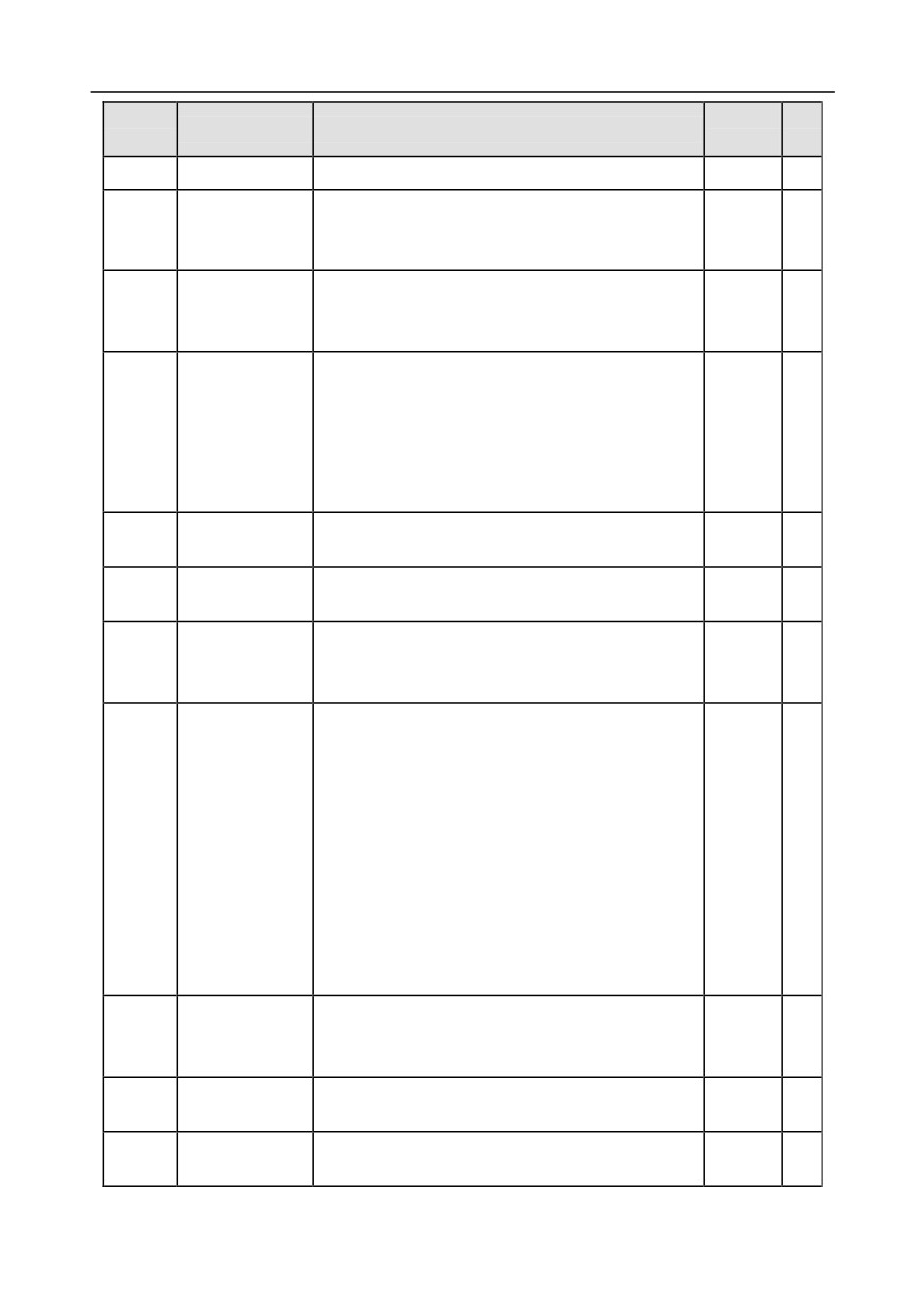
Display torque current reference value under vector
Torque current
P17.34
control mode
0.0A
●
reference
Range: -3000.0-3000.0A
Display the valid value of incoming current on AC
AC incoming
P17.35
side
0.0A
●
current
Range: 0.0-5000.0A
Display output torque value, during forward running,
positive value is motoring state, negative value is
generating state; during reverse running, positive
P17.36
Output torque
0.0Nm
●
value is generating state, negative value is motoring
state.
Range: -3000.0Nm-3000.0Nm
Motor overload
P17.37
0-65535
0
●
count value
Process PID
P17.38
-100.0%-100.0%
0.00%
●
output
Parameter
P17.39
download wrong
0.00-99.00
0.00
●
function code
Ones: Control mode
0: Vector 0
1: Vector 1
2: SVPWM control
3: VC
Motor control
P17.40
Tens: Control state
2
●
mode
0: Speed control
1: Torque control
Hundreds: Motor number
0: Motor 1
1: Motor 2
Upper limit of the
P17.41
torque when
0.0%-300.0% (rated motor current)
180.0%
●
motoring
Upper limit of
P17.42
0.0%-300.0% (rated motor current)
180.0%
●
brake torque
Upper limit
P17.43
0.00-P00.03
50.00Hz
●
frequency of
-197-
Chapter 6
Function
Default
Modi
Name
Detailed parameter description
code
value
fy
forward running
of torque control
Upper limit
frequency of
P17.44
0.00-P00.03
50.00Hz
●
reverse running
of torque control
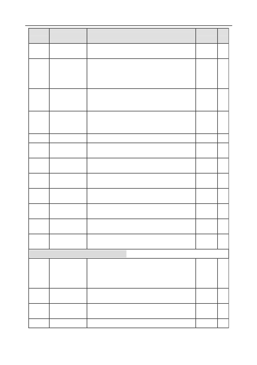
Inertia
P17.45
compensation
-100.0%-100.0%
0.0%
●
torque
Friction
P17.46
compensation
-100.0%-100.0%
0.0%
●
torque
P17.47
Motor pole pairs
0-65535
0
●
Inverter overload
P17.48
0-65535
0
●
count value
Frequency set by
P17.49
0.00-P00.03
0.00Hz
●
A source
Frequency set by
P17.50
0.00-P00.03
0.00Hz
●
B source
PID proportional
P17.51
-100.0%-100.0%
0.00%
●
output
PID integral
P17.52
-100.0%-100.0%
0.00%
●
output
PID differential
P17.53
-100.0%-100.0%
0.00%
●
output
P17.54-
Reserved
0-65535
0
●
P17.63
variables
P18 group Closed-loop control state check
The actual-measured encoder frequency; the value
Actual frequency
of forward running is positive; the value of reverse
P18.00
0.0Hz
●
of encoder
running is negative.
Range: -999.9-3276.7Hz
Encoder position
Encoder count value, quadruple frequency,
P18.01
0
●
count value
Range: 0-65535
Encoder Z pulse
Corresponding count value of encoder Z pulse.
P18.02
0
●
count value
Range: 0-65535
P18.03
High bit of
High bit of position reference value, zero out after
0
●
-198-
Chapter 6
Function
Default
Modi
Name
Detailed parameter description
code
value
fy
position
stop.
reference value
Range: 0-30000
Low bit of
Low bit of position reference value, zero out after
P18.04
position
stop.
0
●
reference value
Range: 0-65535
High bit of
High bit of position feedback value, zero out after
P18.05
position feedback
stop.
0
●
value
Range: 0-30000
Low bit of
Low bit of position feedback value, zero out after
P18.06
position feedback
stop.
0
●
value
Range: 0-65535
Deviation between current reference position and
P18.07
Position deviation actual running position.
0
●
Range: -32768-32767
Position of
Position of reference point of Z pulse when the
P18.08
position
spindle stops accurately.
0
●
reference point
Range: 0-65535
Current position setup when the spindle stops
Current position
P18.09
accurately.
0.00
●
setup of spindle
Range: 0-359.99
Current position
Current position when spindle stops accurately.
P18.10
when spindle
0
●
Range: 0-65535
stops accurately
Z pulse direction display. When the spindle stops
accurately, there may be a couple of pulses’ error
between the position of forward and reverse
Encoder Z pulse
orientation, which can be eliminated by adjusting Z
P18.11
0
●
direction
pulse direction of P20.02 or exchanging phase AB
of encoder.
0: Forward
1: Reverse
Encoder Z pulse
Reserved.
P18.12
0.00
●
angle
Range: 0.00-359.99
Encoder Z pulse
Reserved.
P18.13
0
●
error times
Range: 0-65535
High bit of
P18.14
encoder pulse
0-65535
0
●
count value
-199-
Chapter 6
Function
Default
Modi
Name
Detailed parameter description
code
value
fy
Low bit of
P18.15
encoder pulse
0-65535
0
●
count value
Reserved
P18.16
0-65535
0
●
variables
Pulse command (A2, B2 terminal) is converted to the
Pulse command
set frequency, and it is valid under pulse position
P18.17
0.00Hz
●
frequency
mode and pulse speed mode.
Range: 0-655.35Hz
Pulse command (A2, B2 terminal) is converted to the
Pulse command
set frequency, and it is valid under pulse position
P18.18
0.00Hz
●
feedforward
mode and pulse speed mode.
Range: 0-655.35Hz
The output frequency of the position regulator during
Position regulator
P18.19
position control.
0
●
output
Range: 0-65535
Count value of
Count value of resolver.
P18.20
0
●
resolver
Range: 0-65535
The pole position angle
read
according
to
the
P18.21
Resolver angle
resolver-type encoder.
0.00
●
Range: 0.00-359.99
Pole angle of
closed-loop
Current pole position.
P18.22
0.00
●
synchronous
Range: 0.00-359.99
motor
State control
P18.23
0-65535
0
●
word 3
High bit of count
P18.24
value of pulse
0-65535
0
●
reference
Low bit of count
P18.25
value of pulse
0-65535
0
●
reference
It is the drive ratio
(speed ratio) between
the
Spindle reduction
mounting shaft and the spindle of the encoder when
P18.26
0.000
●
ratio
spindle stops accurately.
Range: 0.000-65.535
P18.27
Encoder UVW
0-7
0
●
-200-
Chapter 6
Function
Default
Modi
Name
Detailed parameter description
code
value
fy
sector
Encoder PPR
(pulse-per-
P18.28
0-65535
0
●
revolution)
display
Angle
compensation
P18.29
value of
-180.0-180.0
0.00
●
synchronous
motor
Reserved
P18.30
0-65535
0
●
variables
Pulse reference
P18.31
0-65535
0
●
Z pulse value
P18.32-
Reserved
0-65535
0
●
P18.35
variables
P19 group Extension card state check
0-65535
0: No card
1: PLC programmable card
2: I/O card
3: Incremental PG card
4: Incremental PG card with UVW
5: Ethernet communication card
6: DP communication card
7: Bluetooth card
8: Resolver PG card
State of card slot
P19.00
9: CANopen communication card
0
●
1
10: WIFI card
11: Profinet communication card
12: Sine/Cosine PG card without CD signal
13: Sine/Cosine PG card with CD signal
14: Absolute encoder PG card
15: CAN master/slave communication card
16: MODBUS communication card
17: EtherCat communication card
18: BacNet communication card
19: DeviceNet communication card
-201-
Chapter 6
Function
Default
Modi
Name
Detailed parameter description
code
value
fy
0-65535
0: No card
1: PLC programmable card
2: I/O card
3: Incremental PG card
4: Incremental PG card with UVW
5: Ethernet communication card
6: DP communication card
7: Bluetooth card
8: Resolver PG card
State of card slot
P19.01
9: CANopen communication card
0
●
2
10: WIFI card
11: Profinet communication card
12: Sine/Cosine PG card without CD signal
13: Sine/Cosine PG card with CD signal
14: Absolute encoder PG card
15: CAN master/slave communication card
16: MODBUS communication card
17: EtherCat communication card
18: BacNet communication card
19: DeviceNet communication card
0-65535
0: No card
1: PLC programmable card
2: I/O card
3: Incremental PG card
4: Incremental PG card with UVW
5: Ethernet communication card
6: DP communication card
State of card slot
7: Bluetooth card
P19.02
0
●
3
8: Resolver PG card
9: CANopen communication card
10: WIFI card
11: Profinet communication card
12: Sine/Cosine PG card without CD signal
13: Sine/Cosine PG card with CD signal
14: Absolute encoder PG card
15: CAN master/slave communication card
16: MODBUS communication card
-202-
Chapter 6
Function
Default
Modi
Name
Detailed parameter description
code
value
fy
17: EtherCat communication card
18: BacNet communication card
19: DeviceNet communication card
Software version
P19.03
of the extension
0.00-655.35
0.00
●
card in card slot 1
Software version
P19.04
of the extension
0.00-655.35
0.00
●
card in card slot 2
Software version
P19.05
of the extension
0.00-655.35
0.00
●
card in card slot 3
Input state of
P19.06
extension I/O
0-0xFFFF
0
●
card terminals
Output state of
P19.07
extension I/O
0-0xFFFF
0
●
card terminals
HDI3 input
frequency of
0.000
P19.08
0.000-50.000kHz
●
extension I/O
kHz
card
AI3 input voltage
P19.09
of extension I/O
0.00-10.00V
0.00V
●
card
P19.10-
Reserved
0-65535
0
●
P19.39
variables
P20 group Encoder of motor 1
0: Incremental encoder
Encoder type
1: Resolver-type encoder
P20.00
0
●
display
2: Sin/Cos encoder
3: Endat absolute encoder
Number of pulses generated
when
the
encoder
Encoder pulse
P20.01
revolves for one circle.
1024
◎
number
Setting range: 0-60000
Ones: AB direction
P20.02
Encoder direction
0: Forward
0x000
◎
1: Reverse
-203-
Chapter 6
Function
Default
Modi
Name
Detailed parameter description
code
value
fy
Tens: Z pulse direction (reserved)
0: Forward
1: Reverse
Hundreds: CD/UVW pole signal direction
0: Forward
1: Reverse
Detection time of
The detection time of encoder offline fault.
P20.03
encoder offline
1.0s
○
Setting range: 0.0-10.0s
fault
Detection time of
Detection time of encoder reversal fault.
P20.04
encoder reversal
0.8s
○
Setting range: 0.0-100.0s
fault
Setting range: 0x00-0x99
Filter times of
Ones: Low-speed filter time, corresponds to 2^(0-
P20.05
encoder
9)×125us.
0x33
○
detection
Tens: High-speed filter times, corresponds to2^(0-
9)×125us.
Speed ratio
Users need to set this parameter when the encoder
between encoder
is not installed on the motor shaft and the drive ratio
P20.06
1.000
○
mounting shaft
is not 1.
and motor
Setting range: 0.001-65.535
Bit0: Enable Z pulse calibration
Bit1: Enable encoder angle calibration
Bit2: Enable SVC speed measurement
Bit3: Select resolver speed measurement mode
Bit4: Z pulse capture mode
Control
Bit5: Do not detect encoder initial angle in v/f control
parameters of
P20.07
Bit6: Enable CD signal calibration
0x3
○
synchronous
Bit7: Disable sin/cos sub-division speed
motor
measurement
Bit8: Do not detect encoder fault during autotuning
Bit9: Enable Z pulse detection optimization
Bit10: Enable initial Z pulse calibration optimization
Bit12: Clear Z pulse arrival signal after stop
0x00-0x11
Enable Z pulse
Ones: Z pulse
P20.08
0x10
○
offline detection
0: Do not detect
1: Enable
-204-
Chapter 6
Function
Default
Modi
Name
Detailed parameter description
code
value
fy
Tens: UVW pulse (for synchronous motor)
0: Do not detect
1: Enable
Relative electric angle of encoder Z pulse and motor
Initial angle of Z
P20.09
pole position.
0.00
○
pulse
Setting range: 0.00-359.99
Relative electric angle of encoder position and motor
Initial angle of the
P20.10
pole position.
0.00
○
pole
Setting range: 0.00-359.99
0-3
Autotuning of
1: Rotary autotuning (DC brake)
P20.11
initial angle of
2: Static autotuning (suitable for resolver-type
0
◎
pole
encoder, sin/cos with CD signal feedback)
3: Rotary autotuning (initial angle identification)
Speed
0: No optimization
measurement
P20.12
1: Optimization mode 1
1
◎
optimization
2: Optimization mode 2
selection
CD signal zero
P20.13
0-65535
0
○
offset gain
Ones: Incremental encoder
0: without UVW
Encoder type
1: with UVW
P20.14
0x00
◎
selection
Tens: Sin/Cos encoder
0: without CD signal
1: with CD signal
Speed
0: PG card
P20.15
measurement
1: local; realized by HDIA and HDIB; supports
0
◎
mode
incremental 24V encoder only
Frequency-divisi
P20.16
0-255
0
○
on coefficient
0x0000-0xffff
Bit0: Enable/disable encoder input filter
0: No filter
Pulse filer
P20.17
1: Filter
0x0011
○
processing
Bit1: Encoder signal filter mode (set Bit0 or Bit2 to 1)
0: Self-adaptive filter
1: Use P20.18 filter parameters
-205-
Chapter 6
Function
Default
Modi
Name
Detailed parameter description
code
value
fy
Bit2: Enable/disable encoder frequency-division
output filter
0: No filter
1: Filter
Bit3: Reserved
Bit4: Enable/disable pulse reference filter
0: No filter
1: Filter
Bit5: Pulse reference filter mode (valid when Bit4 is
set to 1)
0: Self-adaptive filter
1: Use P20.19 filter parameters
Bit6-15: Reserved
Encoder pulse
0-63
P20.18
39
○
filter width
0 means 0.25us
Pulse reference
0-63
P20.19
39
○
filter width
0 means 0.25us
Pulse number of
P20.20
0-65535
1024
◎
pulse reference
Enable angle
compensation of
P20.21
0-1
0
○
synchronous
motor
Switch-over
frequency
threshold of
P20.22
0-630.00Hz
1.00Hz
○
speed
measurement
mode
P20.23-
Reserved
0-65535
0
○
P20.24
variables
P21 group Position control
Ones: Control mode selection
0: Speed control
1: Position control
P21.00
Positioning mode
0x0000
○
Tens: Position command source
0: Pulse string
1: Digital position
-206-
Chapter 6
Function
Default
Modi
Name
Detailed parameter description
code
value
fy
2: Positioning of photoelectric switch during stop
Hundreds: Position feedback source (reserved, fixed
to channel P)
0: PG1
1: PG2
Thousands: servo mode
Bit0: Position deviation mode
0: No deviation
1: With deviation
Bit1: Enable/disable servo
0: Disable (The servo can be enabled by terminals.)
1: Enable
Bit2: (reserved)
Ones: Pulse mode
0: A/B quadrature pulse; A precedes B
1: A: PULSE; B: SIGN
If channel B is of low electric level, the edge counts
up; if channel B is of high electric level, the edge
counts down.
2: A: Positive pulse
Channel A is positive pulse; channel B needs no
wiring
3: A\B dual-channel pulse; channel A pulse edge
counts up, channel B pulse edge counts down
Tens: Pulse direction
Pulse command
Bit0: Set pulse direction
P21.01
0x0000
◎
mode
0: Forward
1: Reverse
Bit1: Set pulse direction by running direction
0: Disable, and BIT0 is valid;
1: Enable
Hundreds: Pulse/direction frequency-doubling
selection (reserved)
0: No frequency-doubling
1: Frequency-doubling
Thousands: Pulse control selection
Bit0: Pulse filter selection
0: Inertia filter
1: Average moving filter
-207-
Chapter 6
Function
Default
Modi
Name
Detailed parameter description
code
value
fy
Bit1: Overspeed control
0: No control
1: Control
Position loop
P21.02
0-400.0
20.0
○
gain 1
Position loop
P21.03
0-400.0
30.0
○
gain 2
0: No switch-over
Switch-over
1: Torque command
P21.04
mode of position
0
○
2: Speed command
loop gain
3-5: Reserved
Torque command
level during
P21.05
0.0-100.0% (rated motor torque)
10.0%
○
position gain
switch-over
Speed command
level during
P21.06
0.0-100.0% (rated motor speed)
10.0%
○
position gain
switch-over
Smooth filter
The smooth filter coefficient during
position
gain
P21.07
coefficient during
switch-over.
5
○
gain switch-over
Setting range: 0-15
The output limit of position regulator, if the limit value
is 0, position regulator will be invalid, and no position
Output limit of
control can be performed, however, speed control is
P21.08
20.0%
○
position controller available.
Setting range: 0.0-100.0% (max. output frequency
P00.03)
When the position deviation is less than P21.09, and
Completion
the duration is larger than P21.10, positioning
P21.09
range of
10
○
completion signal will be outputted.
positioning
Setting range: 0-1000
Detection time for
P21.10
positioning
0.0-1000.0ms
10.0ms
○
completion
Numerator of
Electronic gear ratio, used to adjust the
P21.11
position
corresponding relation between position command
1000
○
command ratio
and actual running displacement.
-208-
Chapter 6
Function
Default
Modi
Name
Detailed parameter description
code
value
fy
Setting range: 1-65535
Denominator of
P21.12
position
Setting range: 1-65535
1000
○
command ratio
Position
0.00-120.00%
P21.13
100.00
○
feedforward gain
For pulse string reference only (position control)
Position
0.0-3200.0ms
P21.14
feedforward filter
3.0ms
○
For pulse string reference only (position control)
time constant
Position
The position feedforward filter time constant during
P21.15
command filter
pulse string positioning.
0.0ms
◎
time constant
0.0-3200.0ms
Bit0: Positioning mode selection
0: Relative position
1: Absolute position (home) (reserved)
Bit1: Positioning cycle selection
0: Cyclic positioning by terminals
1: Automatic cyclic positioning
Bit2: Cycle mode
0: Continuous
1: Repetitive (supported by automatic cyclic
positioning only)
Bit3: P21.17 digital setting mode
0: Incremental
Digital positioning
1: Position type (do not support continuous mode)
P21.16
0
○
mode
Bit4: Home searching mode
0: Search for the home just once
1: Search for the home during each run
Bit5: Home calibration mode
0: Calibrate in real time
1: Single calibration
Bit6: Positioning completion signal selection
0: Valid during the time set by P21.25 (Hold time of
positioning completion signal)
1: Always valid
Bit7: Initial positioning selection (for cyclic
positioning by terminals)
0: Invalid (do not rotate)
-209-
Chapter 6
Function
Default
Modi
Name
Detailed parameter description
code
value
fy
1: Valid
Bit8: Positioning enable signal selection (for cyclic
positioning by terminals only; positioning function is
always enabled for automatic cyclic positioning)
0: Pulse signal
1: Level signal
Bit9: Position source
0: P21.17 setting
1: PROFIBUS/CANopen setting
Bit10-11: Reserved
Bit12: Positioning curve selection (reserved)
0: Straight line
1: S curve
Set digital positioning position;
Position digital
P21.17
Actual position=P21.17×P21.11/P21.12
0
○
reference
0-65535
0: Set by P21.19
1: Set by AI1
Positioning
2: Set by AI2
P21.18
speed setup
0
○
3: Set by AI3
selection
4: Set by high speed pulse HDIA
5: Set by high speed pulse HDIB
Positioning
P21.19
0-100.0% max. frequency
20.0%
○
speed digits
Acceleration time
Set the acceleration/deceleration time of positioning
P21.20
3.00s
○
of positioning
process.
Acceleration time of positioning means the time
needed for the inverter to accelerate from 0Hz to the
max. output frequency (P00.03).
Deceleration time
Deceleration time of positioning means the time
P21.21
3.00s
○
of positioning
needed for the inverter to decelerate from the max.
output frequency (P00.03) to 0hz.
Setting range of P21.20: 0.01-300.00s
Setting range of P21.21: 0.01-300.00s
Set the hold time of waiting when target positioning
Hold time of
P21.22
position is reached.
0.100s
○
positioning arrival
Setting range: 0.000-60.000s
P21.23
Home search
0.00-50.00Hz
2.00Hz
○
-210-
Chapter 6
Function
Default
Modi
Name
Detailed parameter description
code
value
fy
speed
Home position
P21.24
0-65535
0
○
offset
The hold time of positioning completion signal, this
Hold time of
parameter is also valid for positioning completion
P21.25
positioning
0.200s
○
signal of spindle orientation.
completion signal
Setting range: 0.000-60.000s
Pulse
P21.26
superposition
0-65535
0
○
value
Pulse
P21.27
superposition
0-6553.5
8.0
○
speed
Acceleration/dec
eleration time
P21.28
000.0-3000.0s
5.0s
○
after disabling
pulse
Speed
It is the filter time constant detected by pulse string
feedforward filter
when the speed reference source is set to pulse
P21.29
time constant
10.0ms
○
string (P0.06=12 or P0.07=12).
(pulse string
Setting range: 0-3200.0ms
speed mode)
Numerator of the
P21.30
2nd command
1-65535
1000
○
ratio
P21.31-
Reserved
0-65535
0
○
P21.33
variables
P22 group Spindle positioning
Bit0: Enable spindle positioning
0: Disable
1: Enable
Bit1: Select spindle positioning reference point
Spindle
0: Z pulse input
P22.00
positioning mode
0
○
1: S2/S3/S4 terminal input
selection
Bit2: Search for reference point
0: Search the reference point only once
1: Search the reference point every time
Bit3: Enable reference point calibration
-211-

Chapter 6
Function
Default
Modi
Name
Detailed parameter description
code
value
fy
0: Disable
1: Enable
Bit4: Positioning mode selection 1
0: Set direction positioning
1: Near-by direction positioning
Bit5: Positioning mode selection 2
0: Forward positioning
1: Reverse positioning
Bit6: Zeroing command selection
0: Electric level mode
1: Pulse mode
Bit7: Reference point calibration mode
0: Calibrate at the first time
1: Calibrate in real time
Bit8: Action selection after zeroing signal
cancellation (electric level type)
0: Switch to speed mode
1: Position lock mode
Bit9: Positioning completion signal selection
0: Electric level signal
1: Pulse signal
Bit10: Z pulse signal source
0: Motor
1: Spindle
Bit11-15: Reserved
During spindle orientation, the speed of the position
Speed of spindle
point of orientation will be searched, and then it will
P22.01
10.00Hz
○
orientation
switch over to position control orientation.
Setting range: 0.00-100.00Hz
Deceleration time of spindle orientation.
Deceleration time
Spindle orientation deceleration time means the time
P22.02
of spindle
needed for the inverter to decelerate from the max.
3.0s
○
orientation
output frequency (P00.03) to 0Hz.
Setting range: 0.0-100.0s
Users can select the zeroing positions of four
Spindle zeroing
P22.03
spindles by terminals (function code 46, 47).
0
○
position 0
Setting range: 0-39999
Spindle zeroing
P22.04
Setting range: 0-39999
0
○
position 1
-212-
Chapter 6
Function
Default
Modi
Name
Detailed parameter description
code
value
fy
Spindle zeroing
P22.05
Setting range: 0-39999
0
○
position 2
Spindle zeroing
P22.06
Setting range: 0-39999
0
○
position 3
Spindle
Users can select seven spindle scale-division values
P22.07
scale-division
by terminals (function code 48, 49 and 50).
15.00
○
angle 1
Setting range: 0.00-359.99
Spindle
P22.08
scale-division
Setting range: 0.00-359.99
30.00
○
angle 2
Spindle
P22.09
scale-division
Setting range: 0.00-359.99
45.00
○
angle 3
Spindle
P22.10
scale-division
Setting range: 0.00-359.99
60.00
○
angle 4
Spindle
P22.11
scale-division
Setting range: 0.00-359.99
90.00
○
angle 5
Spindle
P22.12
scale-division
Setting range: 0.00-359.99
120.00
○
angle 6
Spindle
P22.13
scale-division
Setting range: 0.00-359.99
180.00
○
angle 7
This function code sets the reduction ratio of the
Spindle drive
P22.14
spindle and the mounting shaft of the encoder.
1.000
○
ratio
Setting range: 0.000-30.000
P22.15 sets spindle zero-point offset, if the selected
Zero-point
spindle zero point is P22.03, the final spindle zero
P22.15
communication
0
○
point will be the sum of P22.03 and P22.15.
setup of spindle
Setting range: 0-39999
Reserved
P22.16
0-65535
0
○
variables
Reserved
P22.17
0-65535
0
○
variables
Rigid tapping
Ones: Enable/disable
P22.18
0x00
◎
selection
0: Disable
-213-
Chapter 6
Function
Default
Modi
Name
Detailed parameter description
code
value
fy
1: Enable
Tens: Analog port selection
0: Invalid
1: AI1
2: AI2
3: AI3
Analog filter time
P22.19
0.0ms-1000.0ms
1.0ms
○
of rigid tapping
Max. frequency
P22.20
0.00-400.00Hz
50.00Hz
○
of rigid tapping
Corresponding
frequency of
P22.21
0.00-10.00Hz
0.00Hz
○
analog zero drift
of rigid tapping
Reserved
P22.22
0-1
0
○
variables
P22.23-
Reserved
0-65535
0
○
P22.24
variables
P23 group Vector control of motor 2
Speed loop
P23.00-P23.05 fit for vector
control
mode
only.
P23.00
proportional gain
Below switch-over frequency 1 (P23.02), the speed
20.0
○
1
loop PI parameters are P23.00 and P23.01. Above
Speed loop
switch-over frequency 2 (P23.05), the speed loop PI
P23.01
0.200s
○
integral time 1
parameters are P23.03 and P23.04; in between
Switch over low
them, the PI parameters are obtained by linear
P23.02
5.00Hz
○
point frequency
variation between two groups of parameters, as
shown in the figure below.
Speed loop
PI parameters
P23.03
proportional gain
20.0
○
(P23.00,P23.01)
2
Speed loop
P23.04
0.200s
○
integral time 2
(P23.03,P23.04)
P23.02
P23.05
Output frequency f
The speed loop dynamic response characteristics of
Switch over high
P23.05
10.00Hz
○
vector control can be adjusted by setting the
point frequency
proportional coefficient and integral time of speed
regulator. Increase proportional gain or decrease
integral time can accelerate dynamic response of
-214-
Chapter 6
Function
Default
Modi
Name
Detailed parameter description
code
value
fy
speed loop, however, if the proportional gain is too
large or integral time is too small, system oscillation
and large overshoot may occur; if proportional gain
is too small, stable oscillation or speed offset may
occur.
Speed loop PI parameter is closely related to the
system inertia, users should make adjustment
according to different load characteristics based on
the default PI parameter to fulfill different needs.
Setting range of P23.00: 0.0-200.0
Setting range of P23.01: 0.000-10.000s
Setting range of P23.02: 0.00Hz-P23.05
Setting range of P23.03: 0.0-200.0
Setting range of P23.04: 0.000-10.000s
Setting range of P23.05: P23.02-P00.03 (max.
output frequency)
Speed loop
P23.06
0-8 (corresponds to 0-2^8/10ms)
0
○
output filter
Slip
compensation
P23.07
coefficient of
Slip compensation coefficient is used to adjust the
100%
○
vector control
slip frequency of vector control to improve system
(motoring)
speed control precision. Users can effectively control
Slip
the static error of speed by adjusting this parameter
compensation
properly.
P23.08
coefficient of
Setting range: 50-200%
100%
○
vector control
(generating)
Current loop
Note:
P23.09
proportional
1. These two parameters are used to adjust PI
1000
○
coefficient P
parameters of current loop; it affects dynamic
response speed and control precision of the system
directly. The default value needs no adjustment
under common conditions;
Current loop
2. Fit for SVC mode 0 (P00.00=0) and VC mode
P23.10
integral
1000
○
(P00.00=3);
coefficient I
3. The value of this function code will be updated
automatically after parameter autotuning of
synchronous motor is done.
-215-
Chapter 6
Function
Default
Modi
Name
Detailed parameter description
code
value
fy
Setting range: 0-65535
Speed loop
P23.11
0.00-10.00s
0.00s
○
differential gain
Proportional
coefficient of
Under VC mode (P00.00=3), below current loop
P23.12
1000
○
high-frequency
high-frequency switch-over threshold
(P23.14),
current loop
current loop PI parameters are P23.09 and P23.10;
Integral
above current loop high-frequency switch-over
coefficient of
threshold, current loop PI parameters are P23.12
P23.13
1000
○
high-frequency
and P23.13.
current loop
Setting range of P23.12: 0-20000
High-frequency
Setting range of P23.13: 0-20000
switch-over
Setting range of P23.14: 0.0-100.0% (relative to
P23.14
100.0%
○
threshold of
max. frequency)
current loop
P23.15-
Reserved
0-65535
0
●
P23.19
variables
P24 group Encoder of motor 2
0: Incremental encoder
Encoder type
1: Resolver-type encoder
P24.00
0
●
display
2: Sin/Cos encoder
3: Endat absolute encoder
Number of pulses generated when the encoder
Encoder pulse
P24.01
revolves for one circle.
1024
◎
number
Setting range: 0-60000
Ones: AB direction
0: Forward
1: Reverse
Tens: Z pulse direction (reserved)
P24.02
Encoder direction
0: Forward
0x000
◎
1: Reverse
Hundreds: CD/UVW pole signal direction
0: Forward
1: Reverse
Detection time of
The detection time of encoder offline fault.
P24.03
encoder offline
1.0s
○
Setting range: 0.0-10.0s
fault
P24.04
Detection time of
Detection time of encoder reversal fault.
0.8s
○
-216-
Chapter 6
Function
Default
Modi
Name
Detailed parameter description
code
value
fy
encoder reversal
Setting range: 0.0-100.0s
fault
Setting range: 0x00-0x99
Filter times of
Ones: Low-speed filter times, corresponds to 2^(0-
P24.05
encoder
9)×125us.
0x33
○
detection
Tens: High-speed filter times; corresponds to 2^(0-
9)×125us.
Speed ratio
Users need to set this parameter when the encoder
between encoder
is not installed on the motor shaft and the drive ratio
P24.06
1.000
○
mounting shaft
is not 1.
and motor
Setting range: 0.001-65.535
Bit0: Enable Z pulse calibration
Bit1: Enable encoder angle calibration
Bit2: Enable SVC speed measurement
Bit3: Select resolver speed measurement mode
Bit4: Z pulse capture mode
Control
Bit5: Do not detect encoder initial angle in v/f control
parameters of
P24.07
Bit6: Enable CD signal calibration
0x3
○
synchronous
Bit7: Disable sin/cos sub-division speed
motor
measurement
Bit8: Do not detect encoder fault during autotuning
Bit9: Enable Z pulse detection optimization
Bit10: Enable initial Z pulse calibration optimization
Bit12: Clear Z pulse arrival signal after stop
0x00-0x11
Ones: Z pulse
Enable Z pulse
Reserved
P24.08
0x10
○
offline detection
Tens: UVW pulse
0: Do not detect
1: Enable
Relative electric angle of encoder Z pulse and motor
Initial angle of Z
P24.09
pole position.
0.00
○
pulse
Setting range: 0.00-359.99
Relative electric angle of encoder position and motor
Initial angle of the
P24.10
pole position.
0.00
○
pole
Setting range: 0.00-359.99
Autotuning of
0-3
P24.11
0
◎
initial angle of
1: Rotary autotuning (DC brake)
-217-
Chapter 6
Function
Default
Modi
Name
Detailed parameter description
code
value
fy
pole
2: Static autotuning (suitable for resolver-type
encoder, sin/cos with CD signal feedback)
3: Rotary autotuning (initial angle identification)
Speed
0: No optimization
measurement
P24.12
1: Optimization mode 1
1
◎
optimization
2: Optimization mode 2
selection
CD signal zero
P24.13
0-65535
0
○
offset gain
Ones: Incremental encoder
0: without UVW
Encoder type
1: with UVW
P24.14
0x00
◎
selection
Tens: Sin/Cos encoder
0: without CD signal
1: with CD signal
Speed
0: PG card
P24.15
measurement
1: local; realized by HDIA and HDIB;
supports
0
◎
mode
incremental 24V encoder only
Frequency-
P24.16
division
0-255
0
○
coefficient
0x0000-0xffff
Bit0: Enable/disable encoder input filter
0: No filter
1: Filter
Bit1: Encoder signal filter mode (set Bit0 or Bit2 to 1)
0: Self-adaptive filter
1: Use P20.18 filter parameters
Bit2: Enable/disable encoder frequency-division
Pulse filer
P24.17
output filter
0x0011
○
processing
0: No filter
1: Filter
Bit3: Reserved
Bit4: Enable/disable pulse reference filter
0: No filter
1: Filter
Bit5: Pulse reference filter mode (valid when Bit4 is
set to 1)
-218-
Chapter 6
Function
Default
Modi
Name
Detailed parameter description
code
value
fy
0: Self-adaptive filter
1: Use P24.19 filter parameters
Bit6-15: Reserved
Encoder pulse
0-63
P24.18
39
○
filter width
0 means 0.25us
Pulse reference
0-63
P24.19
39
○
filter width
0 means 0.25us
Pulse number of
P24.20
0-65535
1024
◎
pulse reference
Enable angle
compensation of
P24.21
0-1
0
○
synchronous
motor
Switch-over
frequency
threshold of
P24.22
0-630.00Hz
1.00Hz
○
speed
measurement
mode
P24.23-
Reserved
0-65535
0
○
P24.24
variables
P25 group Extension I/O card input functions
HDI3 input type
0: HDI3 is high-speed pulse input
P25.00
0
◎
selection
1: HDI3 is digital input
S5 terminal
P25.01
0
◎
function
S6 terminal
P25.02
0
◎
function
S7 terminal
P25.03
0
◎
function
S8 terminal
P25.04
The same with P05 group
0
◎
function
S9 terminal
P25.05
0
◎
function
S10 terminal
P25.06
0
◎
function
HDI3 terminal
P25.07
0
◎
function
-219-
Chapter 6
Function
Default
Modi
Name
Detailed parameter description
code
value
fy
Input terminal
P25.08
polarity of
0x00-0x7F
0x00
○
extension card
0x000-0x7F (0: disable, 1: enable)
BIT0: S5 virtual terminal
BIT1: S6 virtual terminal
Virtual terminal
BIT2: S7 virtual terminal
P25.09
setup of
0x00
◎
BIT3: S8 virtual terminal
extension card
BIT4: S9 virtual terminal
BIT5: S10 virtual terminal
BIT6: HDI3 virtual terminal
HDI3 terminal
P25.10
0.000s
○
switch-on delay
HDI3 terminal
P25.11
0.000s
○
switch-off delay
S5 terminal
P25.12
0.000s
○
switch-on delay
S5 switch-off
P25.13
0.000s
○
delay
S6 terminal
P25.14
0.000s
○
switch-on delay
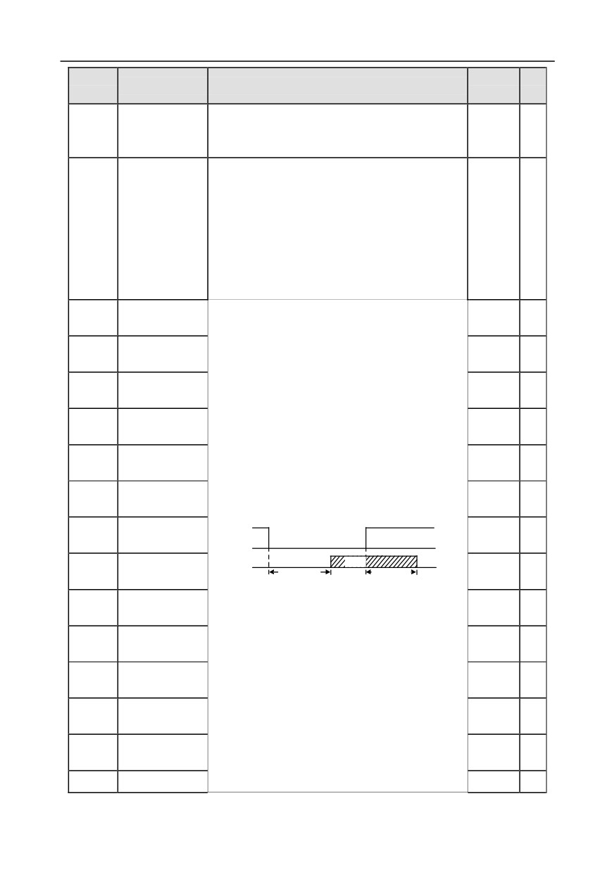
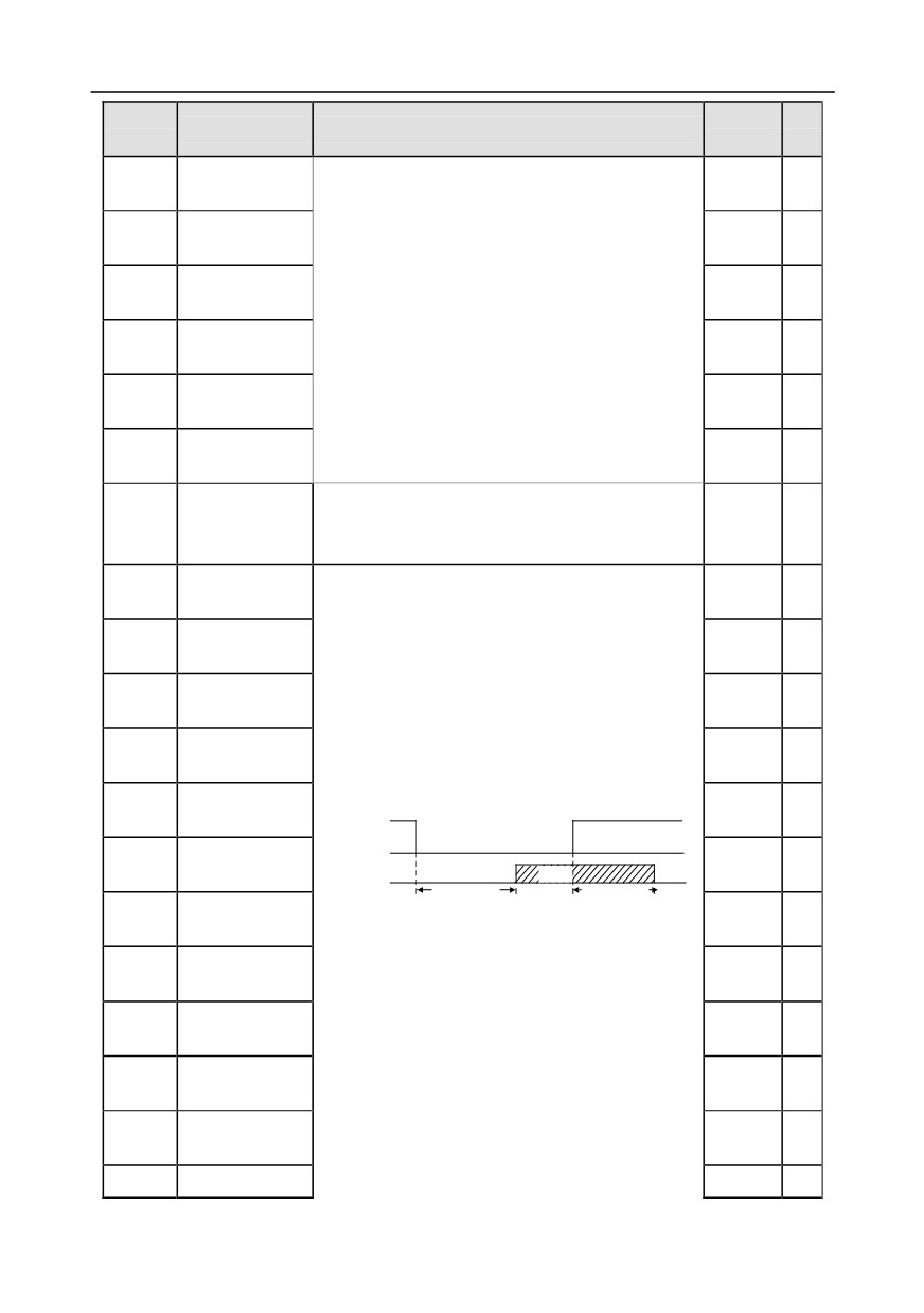
These function codes define corresponding delay of
S6 switch-off
P25.15
the programmable input terminals during level
0.000s
○
delay
variation from switch-on to switch-off .
S7 terminal
P25.16
Si electrical level
0.000s
○
switch-on delay
S7 switch-off
Si valid
invalid
valid
invalid
P25.17
0.000s
○
delay
Switcn-on
Switcn-off
delay
delay
S8 terminal
P25.18
0.000s
○
switch-on delay
Setting range: 0.000-50.000s
S8 switch-off
P25.19
0.000s
○
delay
S9 terminal
P25.20
0.000s
○
switch-on delay
S9 switch-off
P25.21
0.000s
○
delay
S10 terminal
P25.22
0.000s
○
switch-on delay
P25.23
S10 switch-off
0.000s
○
-220-
Chapter 6
Function
Default
Modi
Name
Detailed parameter description
code
value
fy
delay
Lower limit value
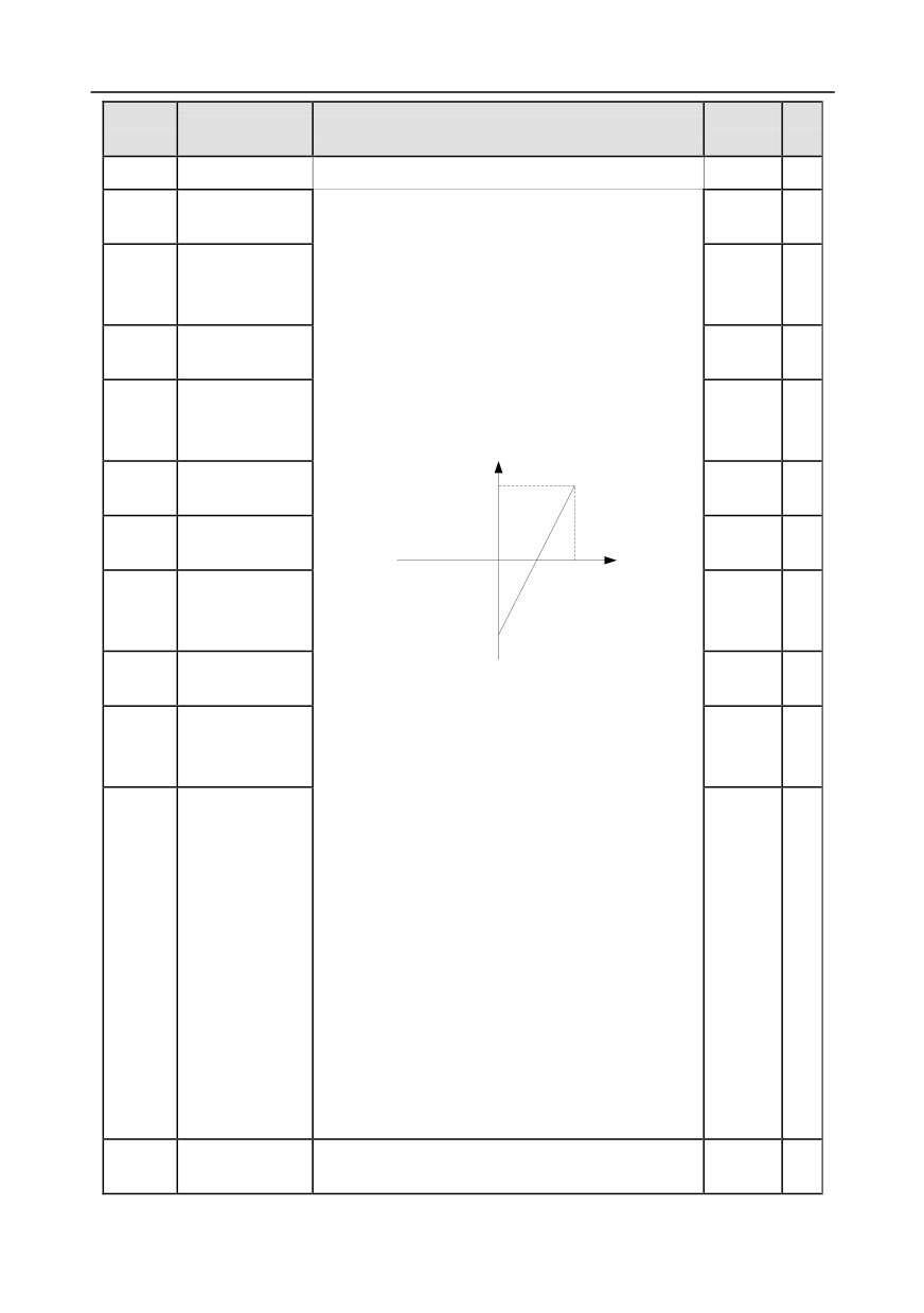
These function codes define the relation between
P25.24
0.00V
○
of AI3
analog input voltage and corresponding set value of
Corresponding
analog input. When the analog input voltage
P25.25
setting of lower
exceeds the range of max./min. input, the max. input
0.0%
○
limit of AI3
or min. input will be adopted during calculation.
Upper limit value
When analog input is current input, 0-20mA current
P25.26
10.00V
○
of AI3
corresponds to 0-10V voltage.
Corresponding
In different application cases, 100% of the analog
P25.27
setting of upper
setting corresponds to different nominal values.
100.0%
○
limit of AI3
The figure below illustrates several settings.
Corresponding
Input filter time of
setting
100%
P25.28
0.030s
○
AI3
Lower limit value
P25.29
0.00V
○
AI
0
of AI4
10V
20mA
Corresponding
AI3/AI4
P25.30
setting of lower
0.0%
○
-100%
limit of AI4
Upper limit value
P25.31
Input filter time: Adjust the sensitivity of analog input,
10.00V
○
of AI4
increase this value properly can enhance the
Corresponding
anti-interference capacity of analog variables;
P25.32
setting of upper
100.0%
○
however, it will also degrade the sensitivity of analog
limit of AI4
input.
Note: AI3 and AI4 can support 0-10V/0-20mA input,
when AI3 and AI4 select
0-20mA input, the
corresponding voltage of 20mA is 10V;
Setting range of P25.24: 0.00V-P25.26
Setting range of P25.25: -100.0%-100.0%
Setting range of P25.26: P25.24-10.00V
Input filter time of
P25.33
Setting range of P25.27: -100.0%-100.0%
0.030s
○
AI4
Setting range of P25.28: 0.000s-10.000s
Setting range of P25.29: 0.00V-P25.31
Setting range of P25.30: -100.0%-100.0%
Setting range of P25.31: P25.29-10.00V
Setting range of P25.32: -100.0%-100.0%
Setting range of P25.33: 0.000s-10.000s
HDI3 high-speed
0: Set input via frequency
P25.34
0
◎
pulse input
1: Count
-221-
Chapter 6
Function
Default
Modi
Name
Detailed parameter description
code
value
fy
function
Lower limit
0.000
P25.35
frequency of
0.000 KHz - P25.37
○
KHz
HDI3
Corresponding
setting of lower
P25.36
-100.0%-100.0%
0.0%
○
limit frequency of
HDI3
Upper limit
50.000
P25.37
frequency of
P25.35 -50.000KHz
○
KHz
HDI3
Corresponding
setting of upper
P25.38
-100.0%-100.0%
100.0%
○
limit frequency of
HDI3
HDI3 frequency
P25.39
0.000s-10.000s
0.030s
○
input filter time
Range: 0-1
AI3 input signal
P25.40
0: Voltage type
0
○
type
1: Current type
Range: 0-1
AI4 input signal
P25.41
0: Voltage type
0
○
type
1: Current type
P25.42-
Reserved
0-65535
0
○
P25.45
variables
P26 group Output functions of extension I/O card
HDO2 output
0: Open collector high-speed pulse output
P26.00
0
◎
type
1: Open collector output
HDO2 output
P26.01
0
○
selection
Y2 output
P26.02
0
○
selection
Y3 output
P26.03
The same with P06.01
0
○
selection
Relay RO3
P26.04
0
○
output selection
Relay RO4
P26.05
0
○
output selection
-222-
Chapter 6
Function
Default
Modi
Name
Detailed parameter description
code
value
fy
Relay RO5
P26.06
0
○
output selection
Relay RO6
P26.07
0
○
output selection
Relay RO7
P26.08
0
○
output selection
Relay RO8
P26.09
0
○
output selection
Relay RO9
P26.10
0
○
output selection
Relay RO10
P26.11
0
○
output selection
Output terminal
0x0000-0x7FF
P26.12
polarity of
0x000
○
RO10, RO9…RO3, HDO2,Y3, Y2 in sequence
extension card
HDO2 switch-on
P26.13
0.000s
○
delay
HDO2 switch-off
P26.14
0.000s
○
delay
Y2 switch-on
P26.15
0.000s
○
delay
Y2 switch-off
P26.16
0.000s
○
delay
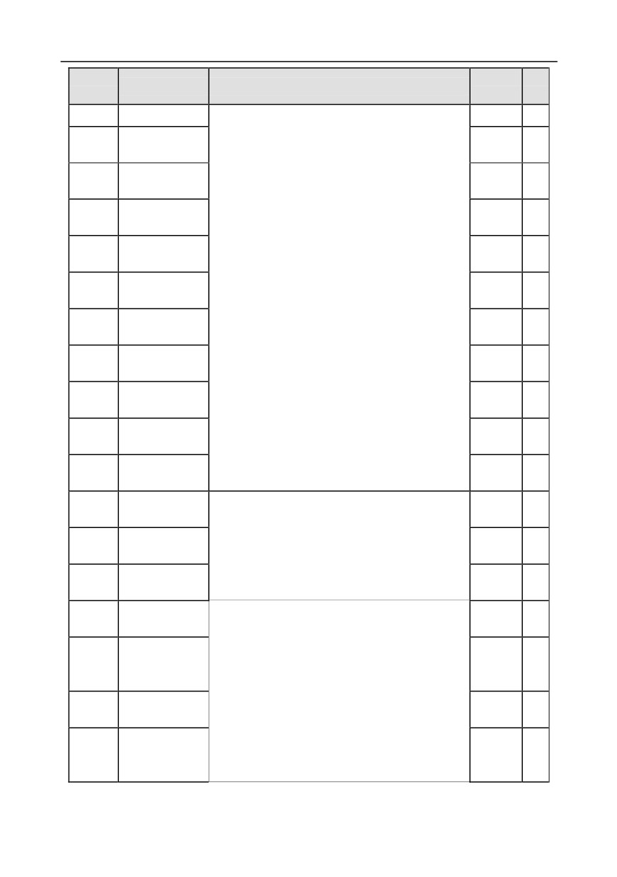
This function code defines the corresponding delay
Y3 switch-on
of the level variation from switch-on to switch-off.
P26.17
0.000s
○
delay
Y electric level
Y3 switch-off
invalid
P26.18
0.000s
○
Y valid
Invalid
Valid
delay
Switch on
Switch off
Relay RO3
delay
delay
P26.19
0.000s
○
switch-on delay
Setting range: 0.000-50.000s
Relay RO3
Note: P26.13 and P26.14 are valid only when
P26.20
0.000s
○
switch-off delay
P26.00 is set to 1.
Relay RO4
P26.21
0.000s
○
switch-on delay
Relay RO4
P26.22
0.000s
○
switch-off delay
Relay RO5
P26.23
0.000s
○
switch-on delay
P26.24
Relay RO5
0.000s
○
-223-
Chapter 6
Function
Default
Modi
Name
Detailed parameter description
code
value
fy
switch-off delay
Relay RO6
P26.25
0.000s
○
switch-on delay
Relay RO6
P26.26
0.000s
○
switch-off delay
Relay RO7
P26.27
0.000s
○
switch-on delay
Relay RO7
P26.28
0.000s
○
switch-off delay
Relay RO8
P26.29
0.000s
○
switch-on delay
Relay RO8
P26.30
0.000s
○
switch-off delay
Relay RO9
P26.31
0.000s
○
switch-on delay
Relay RO9
P26.32
0.000s
○
switch-off delay
Relay RO10
P26.33
0.000s
○
switch-on delay
Relay RO10
P26.34
0.000s
○
switch-off delay
AO2 output
P26.35
0
○
selection
AO3 output
P26.36
The same with P06.14
0
○
selection
Reserved
P26.37
0
○
variables
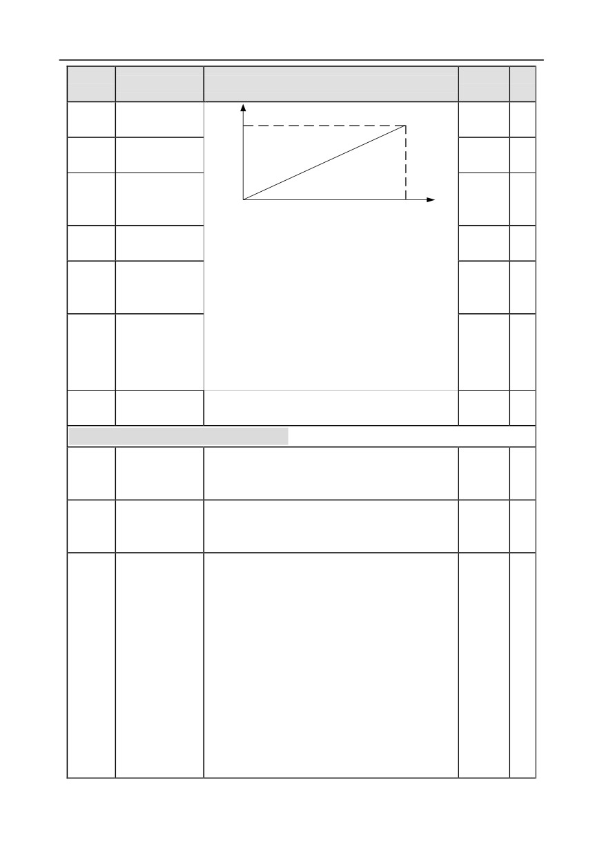
Lower limit of
P26.38
Above function codes define the relation between
0.0%
○
AO2 output
output value and analog output. When the output
Corresponding
value exceeds the set max./min. output range, the
P26.39
AO2 output of
0.00V
○
upper/low limit of output will be adopted during
lower limit
calculation.
Upper limit of
P26.40
When analog output is current output, 1mA
100.0%
○
AO2 output
corresponds to 0.5V voltage. In different
Corresponding
applications, 100% of output value corresponds to
P26.41
AO2 output of
10.00V
○
different analog outputs.
upper limit
-224-
Chapter 6
Function
Default
Modi
Name
Detailed parameter description
code
value
fy
10V (20mA)
AO2 output filter
AO
P26.42
0.000s
○
time
Lower limit of
P26.43
0.0%
○
AO3 output
Corresponding
P26.44
AO3 output of
0.00V
○
0.0%
100.0%
lower limit
Setting range of P26.38: -100.0%-P26.40
Upper limit of
P26.45
Setting range of P26.39: 0.00V-10.00V
100.0%
○
AO3 output
Setting range of P26.40: P26.38-100.0%
Corresponding
Setting range of P26.41: 0.00V-10.00V
P26.46
AO3 output of
10.00V
○
Setting range of P26.42: 0.000s-10.000s
upper limit
Setting range of P26.43: -100.0%-P26.45
Setting range of P26.44: 0.00V-10.00V
AO3 output filter
Setting range of P26.45: P26.43-100.0%
P26.47
0.000s
○
time
Setting range of P26.46: 0.00V-10.00V
Setting range of P26.47: 0.000s-10.000s
P26.48-
Reserved
0-65535
0
○
P26.52
variables
P28 group Master/slave control functions
0: The master/slave control is invalid
0
◎
Master/slave
P28.00
1: This machine is a master
mode selection
2: This machine is a slave
Master/slave
0
◎
0: CAN
P28.01
communication
1: Reserved
data selection
Ones: Master/slave running mode selection
0x001
◎
0: Master/slave mode 0
(The master and slave adopt speed control
and
maintains the power balance by droop control)
1: Master/slave mode 1
(The master and slave must be in the same type of
Master/slave
P28.02
vector control mode. The master is speed control,
control mode
and the slave will be forced to be in the torque
control mode.
2: Master/slave mode 2
Start in the slave first speed mode (master/slave
mode 0) and then switch to torque mode at a certain
frequency point (master/slave mode 1)
-225-
Chapter 6
Function
Default
Modi
Name
Detailed parameter description
code
value
fy
Tens: Slave start command source selection
0: Follow the master to start
1: Determined by P00.01
Hundreds: Slave transmitting/master receiving data
enable
0: Enable
1: Disable
P28.03
Slave speed gain
0.0-500.0%
100.0%
○
P28.04
Slave torque gain
0.0-500.0%
100.0%
○
P28.05
Master/slave
5.00Hz
○
mode 2 speed
mode / torque
0.00-10.00Hz
mode switching
frequency point
P28.06
Number of slaves
0-15
1
◎
P28.07-
Reserved
0-65535
0
○
P28.29
variables
P90 group Customized function group 1
P90.00-
Reserved
0-65535
0
○
P90.39
variables
P91 group Customized function group 2
P91.00-
Reserved
0-65535
0
○
P91.39
variables
P92 group Customized function group 3
P92.00-
Reserved
0-65535
0
○
P92.39
variables
P93 group Customized function group 4
P93.00-
Reserved
0-65535
0
○
P93.39
variables
-226-
Chapter 7
Chapter 7 Troubleshooting
7.1 What this chapter contains
The chapter tells users how to reset faults and check faults history. A complete list of alarms and fault
information as well as possible causes and corrective measures are presented in this chapter.
Only well-trained and qualified professionals are allowed to carry out the
work described in this chapter. Operations should be carried out according to
the instructions presented in Safety precautions.
7.2 Indications of alarms and faults
The fault is indicated by indicators (refer to the "Keypad operation process"). When TRIP indicator is
on, the alarm or fault code displayed in the keypad indicates the inverter is in exception state. This
chapter covers most of the alarms and faults, and their possible causes and corrective measures, if
users cannot figure out the alarm or fault causes, contact local INVT office.
7.3 Fault reset
Users can reset the inverter via STOP/RST key on the keypad, digital inputs, or by cutting off the
inverter power. After faults are removed, the motor can be start again.
7.4 Fault history
P07.27-P07.32 record the six latest fault types; P07.33-P07.40, P07.41-P07.48, and P07.49-
P07.56 record the running data of the inverter when the latest three faults occurred.
7.5 Inverter faults and solutions
When fault occurred, process the fault as shown below.
1. When inverter fault occurred, confirm whether keypad display is improper? If yes, contact INVT;
2. If keypad works properly, check the function codes in P07 group to confirm the corresponding
fault record parameters, and determine the real state when current fault occurred through
parameters;
3. Check the table below to see whether corresponding exception states exist based on the
corresponding corrective measures;
4. Rule out the faults or ask for help from professionals;
5. After confirming faults are removed, reset the fault and start running.
7.5.1 Details of faults and solutions
Fault
Fault type
Possible cause
Corrective measures
code
Inverter unit
Acceleration is too fast;
Increase acceleration time;
OUt1
Phase-U protection
IGBT module is damaged;
Replace the power unit;
Inverter unit
Misacts caused by
Check drive wires;
OUt2
Phase-V protection
interference; drive wires are
Check whether there is strong
Inverter unit
poorly connected ;
interference surrounds the
OUt3
Phase-W protection
To-ground short circuit
peripheral equipment
-227-
Chapter 7
Fault
Fault type
Possible cause
Corrective measures
code
occurs
Over-voltage during
Check input power;
OV1
acceleration
Exception occurred to input
Check whether load
Over-voltage during
voltage;
deceleration time is too short;
OV2
deceleration
Large energy feedback;
or the motor starts during
Lack of brake units;
rotating;
Over-voltage during
Dynamic brake is not
Install dynamic brake units;
OV3
constant speed
enabled
Check the setup of related
running
function codes
Over-current during
Increase acceleration
OC1
acceleration
/deceleration time;
Acceleration is too fast;
Over-current during
Check input power;
OC2
Grid voltage is too low;
deceleration
Select the inverter with larger
Inverter power is too small;
power;
Load transient or exception
Check if the load is short
occurred;
circuited (to-ground short circuit
To-ground short circuit or
or line-to-line short circuit) or
Over-current during
output phase loss occur;
the rotation is not smooth;
OC3
constant speed
Strong external interference
Check the output wiring;
running
sources;
Check if there is strong
Overvoltage stall protection
interference;
is not enabled
Check the setup of related
function codes.
Grid voltage is too low;
Check grid input power;
Bus undervoltage
UV
Overvoltage stall protection
Check the setup of related
fault
is not enabled
function codes
Grid voltage is too low;
Check grid voltage;
Rated motor current is set
Reset rated motor current;
OL1
Motor overload
improperly;
Check the load and adjust
Motor stall or load jumps
torque boost
violently
Acceleration is too fast;
Increase acceleration time;
The motor in rotating is
Avoid restart after stop;
restarted;
Check grid voltage;
OL2
Inverter overload
Grid voltage is too low;
Select the inverter with larger
Load is too large;
power;
Power is too small;
Select proper motor
SPI
Phase loss on input
Phase loss or violent
Check the input power;
-228-
Chapter 7
Fault
Fault type
Possible cause
Corrective measures
code
side
fluctuation occurred to R, S
Check installation wiring
and T input
Phase loss occurred to U, V,
Phase loss on
W output (or the three
Check the output wiring;
SPO
output side
phases of motor is
Check the motor and cable
asymmetrical)
Overheat of rectifier
Air duct is blocked or fan is
OH1
module
damaged;
Ventilate the air duct or replace
Ambient temperature is too
the fan;
Overheat of inverter
OH2
high;
Lower the ambient temperature
module
Long-time overload running
SI external fault input
EF
External fault
Check external device input
terminal acts
Set proper baud rate;
Baud rate is set improperly;
Check the wiring of
Communication line fault;
communication interfaces;
485 communication
Communication address
Set proper communication
CE
fault
error;
address;
Communication suffers from
Replace or change the wiring to
strong interference
enhance anti-interference
capacity
Poor contact of the
Check the connector and
connector of control board;
Current detection
re-plug;
ItE
Hall component is damaged;
fault
Replace the hall component;
Exception occurred to
Replace the main control board
amplification circuit
Motor capacity does not
match with the inverter
Change the inverter model, or
capacity, this fault may occur
adopt V/F mode for control;
easily if the difference
Set proper motor type and
between them is exceeds
nameplate parameters;
five power classes;
Empty the motor load and carry
Motor autotuning
tE
Motor parameter is set
out autotuning again;
fault
improperly;
Check motor wiring and
The parameters gained from
parameter setup;
autotuning deviate sharply
Check whether upper limit
from the standard
frequency is larger than 2/3 of
parameters;
the rated frequency
Autotuning timeout
-229-
Chapter 7
Fault
Fault type
Possible cause
Corrective measures
code
R/W error occurred to the
Press STOP/RST to reset;
EEP
EEPROM fault
control parameters;
Replace the main control board
EEPROM is damaged
PID feedback offline;
Check PID feedback signal
PID feedback offline
PIDE
PID feedback source
wires;
fault
disappears;
Check PID feedback source
Brake circuit fault or brake
Check the brake unit, replace
tube is damaged;
bCE
Brake unit fault
with new brake tubes;
The resistance of external
Increase brake resistance
brake resistor is too small
The actual running time of
Ask help from the supplier,
END
Running time is up
the inverter is larger than the
adjust the set running time
set running time
The inverter releases
Electronic overload
Check the load and overload
OL3
overload pre-alarm based on
fault
pre-alarm threshold
the set value
The keypad wire is poorly
contacted or disconnected;
Check the keypad wires to
The keypad wire is too long
confirm whether fault exists;
Keypad
and suffers strong
Check the surroundings to rule
PCE
communication fault
interference;
out interference source;
Circuit fault occurred to the
Replace the hardware and ask
keypad or communication
for maintenance service
part of the main board
The keypad wire is poorly
contacted or disconnected;
Check the surroundings to rule
The keypad wire is too long
out interference source;
Parameter upload
and suffers strong
Replace the hardware and ask
UPE
error
interference;
for maintenance service;
Circuit fault occurred to the
Replace the hardware and ask
keypad or communication
for maintenance service
part of the main board
The keypad wire is poorly
contacted or disconnected;
Check the surroundings to rule
The keypad wire is too long
out interference source;
Parameter download
DNE
and suffers strong
Replace the hardware and ask
error
interference;
for maintenance service;
Data storage error occurred
Re-backup keypad data
to the keypad
-230-
Chapter 7
Fault
Fault type
Possible cause
Corrective measures
code
Inverter output is short
Check whether motor wiring is
connected to the ground;
proper;
Current detection circuit is
Replace the hall component;
To-ground short
ETH1
faulty;
Replace the main control
circuit fault 1
Actual motor power setup
board;
deviates sharply from the
Reset the motor parameters
inverter power
properly
Inverter output is short
Check whether motor wiring is
connected to ground;
proper;
Current detection circuit is
Replace the hall component;
To-ground short
ETH2
faulty;
Replace the main control
circuit fault 1
Actual motor power setup
board;
deviates sharply from the
Reset the motor parameters
inverter power
properly
Check the load to ensure it is
proper, increase the detection
Speed deviation
Load is too heavy, or stall
dEu
time;
fault
occurred
Check whether control
parameters are set properly
Control parameters of
Check the load to ensure it is
synchronous motor is set
proper,
improperly;
Check whether load is proper;
STo
Maladjustment fault
The parameter gained from
Check whether control
autotuning is inaccurate;
parameters are set correctly;
The inverter is not
Increase maladjustment
connected to motor
detection time
The inverter performs
Electronic underload
Check the load and overload
LL
underload pre-alarm based
fault
pre-alarm threshold
on the set value
Encoder line sequence is
ENC1O
Encoder offline fault
wrong, or signal wires are
Check the encoder wiring
poorly connected
The encoder speed signal is
Encoder reversal
ENC1D
contrary to the motor running
Reset encoder direction
fault
direction
Encoder Z pulse
Z signal wires are
ENC1Z
Check the wiring of Z signal
offline fault
disconnected
Motor
Motor over-temperature
Check the wiring of motor
OT
over-temperature
input terminal is valid;
over-temperature input terminal
-231-
Chapter 7
Fault
Fault type
Possible cause
Corrective measures
code
fault
Exception occurred to t
(terminal function 57);
temperature detection
Check whether temperature
Exception occurred to
sensor is proper;
resistor;
Check the motor and perform
Long-time overload running
maintenance on the motor
or exception occurred
Safe torque off function is
STO
Safe torque off
/
enabled by external forces
The wiring of STO is
Check whether terminal wiring
improper;
of STO is proper and firm
Exception occurred
Fault occurred to external
enough;
STL1
to safe circuit of
switch of STO;
Check whether external switch
channel H1
Hardware fault occurred to
of STO can work properly;
safety circuit of channel H1
Replace the control board
The wiring of STO is
Check whether terminal wiring
improper;
of STO is proper and firm
Exception occurred
Fault occurred to external
enough;
STL2
to channel H2 safe
switch of STO;
Check whether external switch
circuit
Hardware fault occurred to
of STO can work properly;
safety circuit of channel H2
Replace the control board
Exception occurred
Hardware fault occurred to
STL3
to channel H1 and
Replace the control board
STO circuit
channel H2
Safety code FLASH
CrCE
Control board is faulty
Replace the control board
CRC check fault
Users should not insert two
cards with the same type;
Repetitive extension
The two inserted extension
E-Err
check the type of extension
card type
cards are of the same type
card, and remove one card
after power down
Encoder UVW loss
No electric level variation
Check the wiring of UVW;
ENCUV
fault
occurred to UVW signal
Encoder is damaged
Confirm whether the extension
card inserted can be
There is data transmission in
Failed to identify the
supported;
interfaces of card slot 1,
F1-Er
extension card in
Stabilize the extension card
however, it cannot read the
card slot 1
interfaces after power down,
card type
and confirm whether fault still
occurs at next power-on;
-232-
Chapter 7
Fault
Fault type
Possible cause
Corrective measures
code
Check whether the insertion
port is damaged, if yes, replace
the insertion port after power
down
Confirm whether the extension
card inserted can be supported;
Stabilize the extension card
There is data transmission in
interfaces after power down,
Failed to identify the
interfaces of card slot 2,
and confirm whether fault still
F2-Er
extension card in
however, it cannot read the
occurs at next power-on;
card slot 2
card type
Check whether the insertion
port is damaged, if yes, replace
the insertion port after power
down
Confirm whether the extension
card inserted can be supported;
Stabilize the extension card
There is data transmission in
interfaces after power down,
Failed to identify the
interfaces of card slot 3,
and confirm whether fault still
F3-Er
the extension card in
however, it cannot read the
occurs at next power-on;
card slot 3
card type
Check whether the insertion
port is damaged, if yes, replace
the insertion port after power
down
Confirm whether the extension
card inserted can be supported;
Stabilize the extension card
Communication
interfaces after power down,
There is no data
timeout occurred to
and confirm whether fault still
C1-Er
transmission in interfaces of
the extension card in
occurs at next power-on;
card slot 1
card slot 1
Check whether the insertion
port is damaged, if yes, replace
the insertion port after power
down
Confirm whether the extension
Communication
There is no data
card inserted can be supported;
timeout occurred to
C2-Er
transmission in interfaces of
Stabilize the extension card
the extension card in
card slot 2
interfaces after power down,
card slot 2
and confirm whether fault still
-233-
Chapter 7
Fault
Fault type
Possible cause
Corrective measures
code
occurs at next power-on;
Check whether the insertion
port is damaged, if yes, replace
the insertion port after power
down
Confirm whether the extension
card inserted can be supported;
Stabilize the extension card
Communication
interfaces after power down,
There is no data
timeout occurred to
and confirm whether fault still
C3-Er
transmission in interfaces of
the extension card in
occurs at next power-on;
card slot 3
card slot 3
Check whether the insertion
port is damaged, if yes, replace
the insertion port after power
down
There is no data
Profibus card
Check whether the
transmission between the
E-DP
communication
communication card wiring is
communication card and the
timeout fault
loose or dropped
host computer (or PLC)
There is no data
Check whether the
Ethernet card
transmission between the
communication card wiring is
E-NET
communication
communication card and the
loose or dropped
timeout fault
host computer
There is no data
Check whether the
CANopen card
transmission between the
communication card wiring is
E-CAN
communication
communication card and the
loose or dropped
timeout fault
host computer (or PLC)
There is no data
Check whether the
Profinet card
transmission between the
communication card wiring is
E-PN
communication
communication card and the
loose or dropped
timeout fault
host computer (or PLC)
There is no data
Check whether the
EtherCat card
transmission between the
communication card wiring is
E-CAT
communication
communication card and the
loose or dropped
timeout fault
host computer (or PLC)
There is no data
Check whether the
BACNet card
transmission between the
communication card wiring is
E-BAC
communication
communication card and the
loose or dropped
timeout fault
host computer (or PLC)
-234-