Goodrive350 Series High-performance Multi-function Inver ter. Operation manual - page 4
Chapter 5
layer.
b) Determine Z pulse direction
Set P00.10=20Hz, and set P00.13 (running direction) to forward and reverse direction respectively to
observe whether the difference value of P18.02 is less than 5, if the difference value remains to be
larger than 5 after setting Z pulse reversal function of P20.02, power off and exchange phase A and
phase B of the encoder, and then observe the difference between the value of P18.02 during forward
and reverse rotation. Z pulse direction only affects the forward/reverse positioning precision of the
spindle positioning carried out with Z pulse.
Step 5: Closed-loop vector pilot-run
Set P00.00=3, and carry out closed-loop vector control, adjust P00.10 and speed loop and current
loop PI parameter in P03 group to make it run stably in the whole range.
Step 6: Flux-weakening control
Set flux-weakening regulator gain P03.26=0-8000, and observe the flux-weakening control effect.
P03.22-P03.24 can be adjusted as needed.
2. Commissioning procedures for closed-loop vector control of synchronous motor
Step 1: Set P00.18=1, restore to default value
Step 2: Set P00.00=3 (VC) , set P00.03, P00.04, and motor nameplate parameters in P02 group.
Step 3: Set P20.00 and P20.01 encoder parameters
When the encoder is resolver-type encoder, set the encoder pulse count value to (resolver
pole pair number × 1024), eg, if pole pair number is 4, set P20.01 to 4096.
Step 4: Ensure the encoder is installed and set correctly
When motor stops, observe whether P18.21 (resolver angle) fluctuates, if it fluctuates
sharply, check the wiring and grounding. Rotates the motor slowly, observe whether P18.21
changes accordingly, if yes, it indicates motor is connected correctly; if the value of P18.02
keeps constant at a non-zero value after rotating for multiple circles, it indicates encoder Z
signal is correct.
Step 5: Autotuning of initial position of magnetic pole
Set P20.11=2 or 3 (3: rotary autotuning; 2: static autotuning), press RUN key to run the
inverter.
a) Rotary autotuning (P20.11 = 3)
Detect the position of current magnetic pole when autotuning starts, and then accelerates to 10Hz,
autotuning corresponding magnetic pole position of encoder Z pulse, and decelerate to stop.
During running, if ENC1O or ENC1D fault occurred, set P20.02=1 and carry out autotuning again.
After autotuning is done, the angle obtained from autotuning will be saved in P20.09 and P20.10
automatically.
-115-
Chapter 5
b) Static autotuning
In cases where the load can be disconnected, it is recommended to adopt rotary autotuning
(P20.11=3) as it has high angle precision. If the load cannot be disconnected, users can adopt static
autotuning (P20.11=2). The magnetic pole position obtained from autotuning will be saved in P20.09
and P20.10.
Step 6: Closed-loop vector pilot-run
Adjust P00.10 and speed loop and current loop PI parameter in P03 group to make it run stably in the
whole range. If oscillation occurred, reduce the value of P03.00, P03.03, P03.09 and P03.10. If
current oscillation noise occurred during low speed, adjust P20.05.
Note: It is necessary to re-determine P20.02 (encoder direction) and carry out magnetic pole
position autotuning again if the wiring of motor or encoder is changed.
3. Commissioning procedures for pulse string control
Pulse input is operated based on closed-loop vector control; speed detection is needed in the
subsequent spindle positioning, zeroing operation and division operation.
Step 1: Restore to default value by keypad
Step 2: Set P00.03, P00.04 and motor nameplate parameters in P02 group
Step 3: Motor parameter autotuning: rotary parameter autotuning or static parameter autotuning
Step 4: Verity the installation and settings of encoder. Set P00.00=3 and P00.10=20Hz to run the
system, and check the control effect and performance of the system.
Step 5: Set P21.00=0001 to set positioning mode to position control, namely pulse-string control.
There are four kinds of pulse command modes, which can be set by P21.01 (pulse command mode).
Under position control mode, users can check high bit and low bit of position reference and feedback,
P18.02 (count value of Z pulse), P18.00 (actual frequency of encoder), P18.17 (pulse command
frequency) and P18.19 (position regulator output) via P18, through which users can figure out the
relation between P18.8 (position of position reference point) and P18.02, pulse command frequency
P18.17, feedforward P18.18 and position regulator output P18.19.
Step 6: The position regulator has two gains, namely P21.02 and P21.03, and they can be switched
by speed command, torque command and terminals.
Step 7: When P21.08 (output limit of position controller) is set to 0, the position control will be invalid,
and at this point, the pulse string acts as frequency source, P21.13 (position feedforward gain) should
be set to 100%, and the speed acceleration/deceleration time is determined by the acceleration
/deceleration time of pulse string, the pulse string acceleration/deceleration time of the system can be
adjusted. If the pulse string acts as the frequency source in speed control, users can also set P21.00
to 0000, and set the frequency source reference P00.06 or P00.07 to 12 (set by pulse string AB), at
this point, the acceleration/deceleration time is determined by the acceleration/deceleration time of
the inverter, meanwhile, the parameters of pulse string AB is still set by P21 group. In speed mode,
the filter time of pulse string AB is determined by P21.29.
-116-
Chapter 5
Step 8: The input frequency of pulse string is the same with the feedback frequency of encoder pulse,
the relation between them can be changed by altering P21.11 (numerator of position command ratio)
and P21.12 (denominator of position command ratio)
Step 9: When running command or servo enabling is valid (by setting P21.00 or terminal function 63),
it will enter pulse string servo running mode.
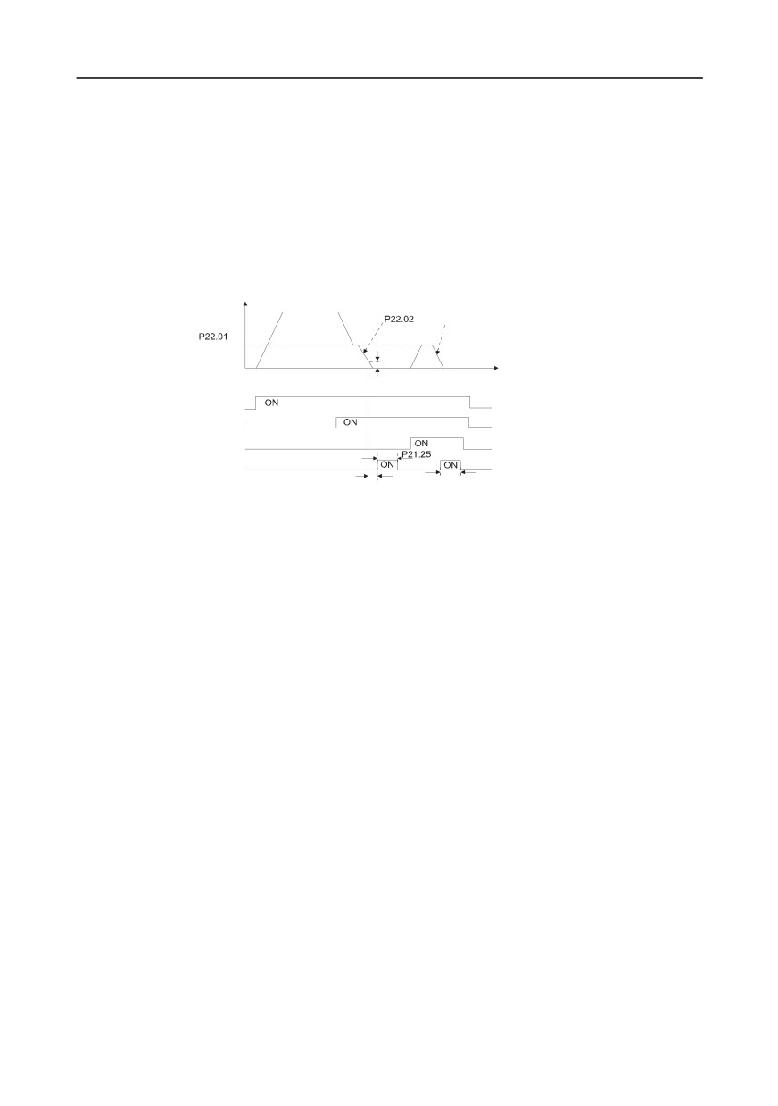
4. Commissioning procedures for spindle positioning
Spindle orientation is to realize orientation functions like zeroing and division based on closed-loop
vector control
Frequency
Deceleration time of spindle orientation
Speed of
accurate-stop
of spindle
P21.09 Completion
Time
range of positioning
Running command
Zeroing command
Zeroing selection terminal 1
Hold time of positioning completion signal
Positioning completion signal
P21.10 Detection time
P21.25 Hold time of positioning completion signal
for positioning completion
Step 1-4: These four steps are the same with the first four steps of the commissioning procedures for
closed-loop vector control, which aim to fulfill the control requirements of closed-loop vector control,
thus realizing spindle positioning function in either position control or speed control mode.
Step 5: Set P22.00.bit0=1 to enable spindle positioning, set P22.00.bit1 to select spindle zero input. If
the system adopts encoder for speed measurement, set P22.00.bit1 to 0 to select Z pulse input; if the
system adopts photoelectric switch for speed measurement, set P22.00.bit1 to
1 to select
photoelectric switch as zero input; set P22.00.bit2 to select zero search mode, set P22.00.bit3 to
enable or disable zero calibration, and select zero calibration mode by setting P22.00.bit7.
Step 6: Spindle zeroing operation
a) Select the positioning direction by setting P22.00.bit4;
b) There are four zero positions in P22 group, users can choose one out of four zeroing positions
by setting zeroing input terminal selection (46, 47) in P05 group. When executing zeroing function,
the motor will stop accurately at corresponding zeroing position according to the set positioning
direction, which can be viewed via P18.10;
c) The positioning length of spindle zeroing is determined by the deceleration time of
accurate-stop and the speed of accurate-stop;
Step 7: Spindle division operation
There are seven scale-division positions in P22 group, users can choose one out of seven
scale-division positions by setting scale-division input terminal selection (48, 49, 50) in P05 group.
Enable corresponding scale-division terminal after the motor stops accurately, and the motor will
-117-
Chapter 5
check the scale-division position state and switch to corresponding position incrementally, at this point,
users can check P18.09.
Step 8: Priority level of speed control, position control and zeroing
The priority level of speed running is higher than that of the scale division, when the system runs in
scale-division mode, if spindle orientation is prohibited, the motor will turn to speed mode or position
mode.
The priority level of zeroing is higher than that of the scale division.
Scale-division command is valid when the scale-division terminal is from 000 state to non-000 state,
eg, in 000-011, the spindle executes scale division 3. The transition time during terminal switch-over
needs to be less than 10ms; otherwise, wrong scale division command may be executed.
Step 9: Hold positioning
The position loop gain during positioning is P21.03; while the position loop gain in
positioning-completion-hold state is P21.02. In order to keep sufficient position-hold force and ensure
no system oscillation occurred, adjust P03.00, P03.01, P20.05 and P21.02.
Step 10: Positioning command selection (bit6 of P22.00)
Electric level signal: Positioning command (zeroing and scale division) can be executed only when
there is running command or the servo is enabled.
Step 11: Spindle reference point selection (bit0 of P22.00)
Encoder Z pulse positioning supports the following spindle positioning modes:
a) the encoder is installed on the motor shaft, the motor shaft and spindle is 1:1 rigid connection;
b) the encoder is installed on the motor shaft, the motor shaft and spindle is 1:1 belt connection;
At this point, the belt may slip during high-speed running and cause inaccurate positioning, it is
recommended to install proximity switch on the spindle.
c) The encoder is installed on the spindle, and the motor shaft is connected to the spindle with
belt, the drive ratio is not necessarily 1:1;
At this point, set P20.06 (speed ratio of the mounting shaft between motor and encoder), and set
P22.14 (spindle drive ratio) to 1. As the encoder is not installed on the motor, the control performance
of closed-loop vector will be affected.
Proximity switch positioning supports the following spindle positioning modes:
a) The encoder is installed on the motor shaft, the drive ratio between motor shaft and spindle is
not necessarily 1:1;
At this point, it is required to set P22.14 (spindle drive ratio).
5. Commissioning procedures for digital positioning
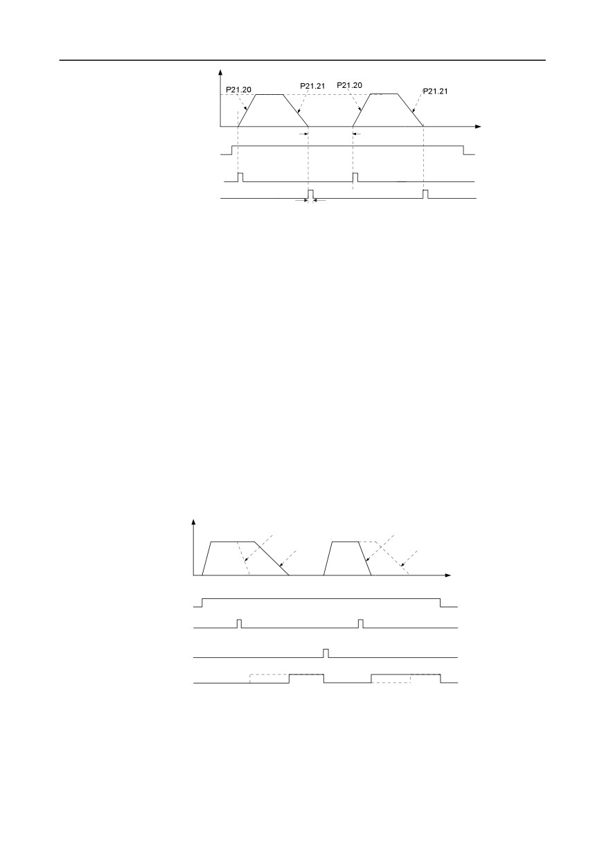
The diagram for digital positioning is shown below.
-118-
Chapter 5
Frequency
Positioning
speed
P21.22 Hold time
Time
of positioning arrival
Running command
Cyclic positioning
enable signal terminal
Positioning completion signal
P21.25 Hold time of positioning completion signal
Step 1-4: These four steps are the same with the first four steps of the commissioning procedures for
closed-loop vector control, which aim to fulfill the control requirements of closed-loop vector control.
Step 5: Set P21.00=0011 to enable digital positioning. Set P21.17, P21.11 and P21.12
(set
positioning displacement) according to actual needs ; set P21.18 and P21.19 (set positioning speed);
set P21.20 and P21.21 (set acceleration/deceleration time of positioning).
Step 6: Single positioning operation
Set P21.16.bit1=0, and the motor will carry out single positioning action and stay in the positioning
position according to the setup in step 5.
Step 7: Cyclic positioning operation
Set P21.16.bit1=1 to enable cyclic positioning. The cyclic positioning is divided into continuous mode
and repetitive mode; users can also carry out cyclic positioning through terminal function (no. 55,
enable digital positioning cycle)
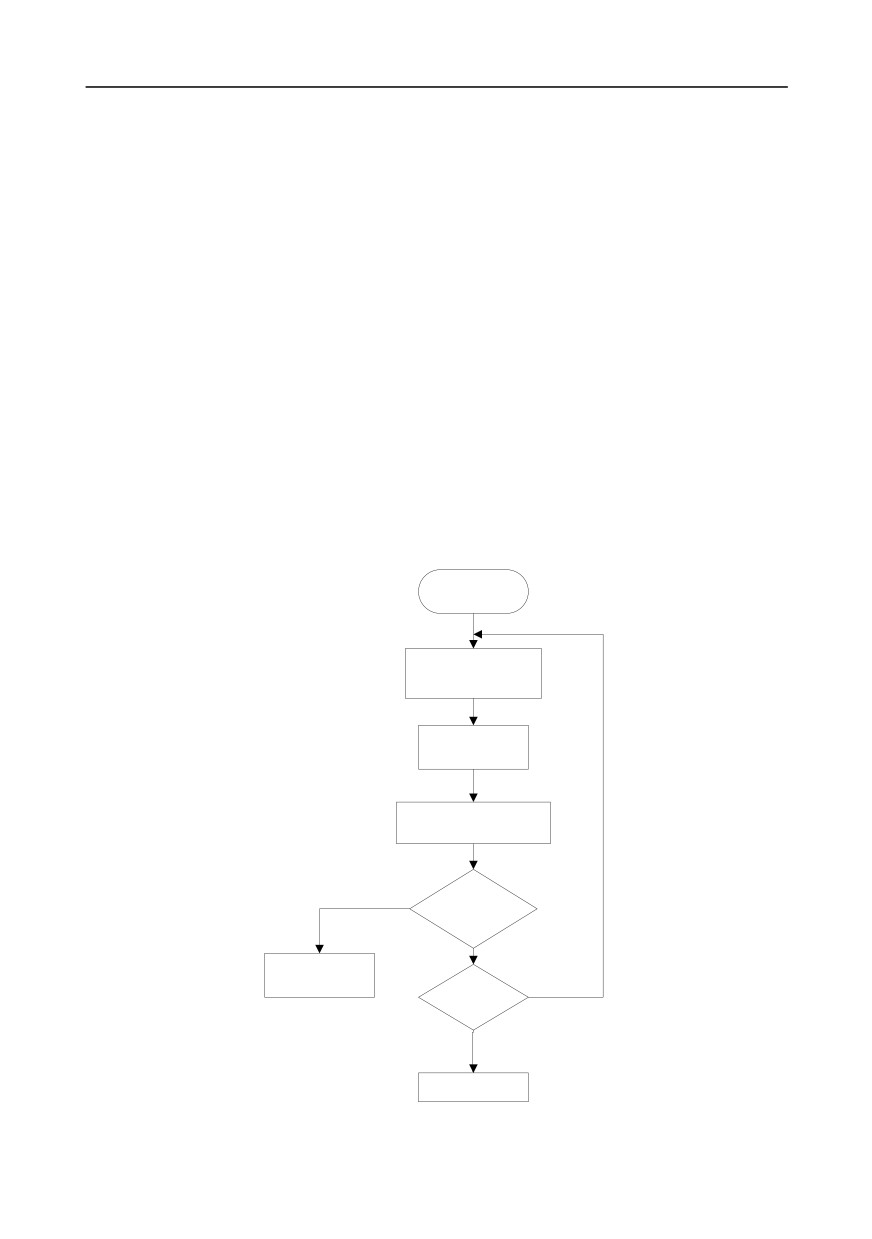
6. Commissioning procedures for positioning of photoelectric switch
Photoelectric switch positioning is to realize positioning function based on closed-loop vector control.
Frequency
Directdeceleration positioning
Directdeceleration positioning
Constant speed+
deceleration positioning
Constant speed+
deceleration positioning
Time
Running command
Photoelectric switch
arrival signal
Cyclic positioning
enable signal
Positioning completion
signal
Step 1-4: These four steps are the same with the first four steps of the commissioning procedures for
closed-loop vector control, which aim to fulfill the control requirements of closed-loop vector control.
Step 5: Set P21.00=0021 to enable photoelectric switch positioning, the photoelectric switch signal
can be connected to S8 terminal only, and set P05.08=43, meanwhile, set P21.17, P21.11 and
-119-
Chapter 5
P21.12 (set positioning displacement) based on actual needs; set P21.21 (deceleration time of
positioning), however, when present running speed is too fast or the set positioning displacement is
too small, the deceleration time of positioning will be invalid, and it will enter direct deceleration
positioning mode.
Step 6: Cyclic positioning
After positioning is done, the motor will stay in current position. Users can set cyclic positioning
through input terminal function selection (55: enable cyclic digital positioning) in P05 group; when the
terminal receives cyclic positioning enable signal (pulse signal), the motor will continue running in the
set speed as per the speed mode and re-enter positioning state after encountering photoelectric
switch.
(7) Hold positioning
The position loop gain during positioning is P21.03; while the position loop gain in
positioning-completion-hold state is P21.02. In order to keep sufficient position-hold force and ensure
no system oscillation occurred, adjust P03.00, P03.01, P20.05 and P21.02.
5.5.19 Fault handling
GD350 series inverter provides abundant information concerning fault handling for the convenience
of the users.
In running
Fault occurred, and the
keypad displayed fault
code
Figure out the fault
cause based on the
fault code
Figure out the most possible
cause according to P07.33-
P07.40
N
Rule out
fault based on
corresponding
solutions
Y
Consult with INVT
N
Run again
Y
Proper running
-120-

Chapter 5
Related parameter list:
Function
Default
Name
Detailed parameter description
code
value
P07.27
Type of present fault
0: No fault
0
P07.28
Type of the last fault
1: Inverter unit U phase protection (OUt1)
/
P07.29
Type of the last but one fault
2: Inverter unit V phase protection (OUt2)
/
P07.30
Type of the last but two fault
3: Inverter unit W phase protection
/
Type of the last but three
(OUt3)
P07.31
/
fault
4: Overcurrent during acceleration (OC1)
5: Overcurrent during deceleration (OC2)
6: Overcurrent during constant speed
(OC3)
7: Overvoltage during acceleration (OV1)
8: Overvoltage during deceleration (OV2)
9: Overvoltage during constant speed
(OV3)
10: Bus undervoltage fault (UV)
11: Motor overload (OL1)
12: Inverter overload (OL2)
13: Phase loss on input side (SPI)
14: Phase loss on output side (SPO)
15: Rectifier module overheat (OH1)
16: Inverter module overheat (OH2)
17: External fault (EF)
18: 485 communication fault (CE)
P07.32
Type of the last but four fault
19: Current detection fault (ItE)
20: Motor autotuning fault (tE)
21: EEPROM operation fault (EEP)
22: PID feedback offline fault (PIDE)
23: Brake unit fault (bCE)
24: Running time reached (END)
25: Electronic overload (OL3)
26: Keypad communication error (PCE)
27: Parameter upload error (UPE)
28: Parameter download error
(DNE)
29: Profibus DP communication fault
(E-DP)
30: Ethernet communication fault
(E-NET)
31: CANopen communication fault
(E-CAN)
-121-
Chapter 5
Function
Default
Name
Detailed parameter description
code
value
32: To-ground short-circuit fault 1 (ETH1)
33: To-ground short-circuit fault 2 (ETH2)
34: Speed deviation fault (dEu)
35: Mal-adjustment fault (STo)
36: Underload fault (LL)
37: Encoder offline fault (ENC1O)
38: Encoder reversal fault (ENC1D)
39: Encoder Z pulse offline fault (ENC1Z)
40: Safe torque off (STO)
41: Channel H1 safety circuit exception
(STL1)
42: Channel H2 safety circuit exception
(STL2)
43: Channel H1 and H2 exception (STL3)
44: Safety code FLASH CRC check fault
(CrCE)
55: Repetitive extension card type fault
(E-Err)
56: Encoder UVW loss fault (ENCUV)
57: Profinet communication timeout fault
(E-PN)
58: CAN communication fault (SECAN)
59: Motor over-temperature fault (OT)
60: Card slot 1 card identification failure
(F1-Er)
61: Card slot 2 card identification failure
(F2-Er)
62: Card slot 3 card identification failure
(F3-Er)
63: Card slot 1 card communication
timeout fault (C1-Er)
64: Card slot 2 card communication
timeout fault (C2-Er)
65: Card slot 3 card communication
timeout fault (C3-Er)
66: EtherCat communication fault
(E-CAT)
67: Bacnet communication fault (E-BAC)
68: DeviceNet communication fault
-122-
Chapter 5
Function
Default
Name
Detailed parameter description
code
value
(E-DEV)
69: Master-slave synchronous CAN
slave fault (S-Err)
P07.33
Running frequency of present fault
0.00Hz
P07.34
Ramps reference frequency of present fault
0.00Hz
P07.35
Output voltage of present fault
0V
P07.36
Output current of present fault
0.0A
P07.37
Bus voltage of present fault
0.0V
P07.38
Max. temperature of present fault
0.0°C
P07.39
Input terminal state of present fault
0
P07.40
Output terminal state of present fault
0
P07.41
Running frequency of the last fault
0.00Hz
P07.42
Ramps reference frequency of the last fault
0.00Hz
P07.43
Output voltage of the last fault
0V
P07.44
Output current of the last fault
0.0A
P07.45
Bus voltage of the last fault
0.0V
P07.46
Max. temperature of the last fault
0.0°C
P07.47
Input terminal state of the last fault
0
P07.48
Output terminal state of the last fault
0
P07.49
Running frequency of the last but one fault
0.00Hz
P07.50
Ramps reference frequency of the last but one fault
0.00Hz
P07.51
Output voltage of the last but one fault
0V
P07.52
Output current of the last but one fault
0.0A
P07.53
Bus voltage of the last but one fault
0.0V
P07.54
Max. temperature of the last but one fault
0.0°C
P07.55
Input terminal state of the last but one fault
0
P07.56
Output terminal state of the last but one fault
0
-123-
Chapter 6
Chapter 6 Function parameter list
6.1 What this chapter contains
This chapter lists all the function codes and corresponding description of each function code.
6.2 Function parameter list
Function parameters of GD350 series inverter are categorized according to functions. Among the
function groups, P98 is analog input/output calibration group, and P99 is factory function group which
cannot be accessed by users. The function code adopts three-level menu, eg, "P08.08" indicates it is
the no. 8 function code in P8 group.
The function group no. corresponds to the first-level menu; function code no. corresponds to the
second-level menu; function code parameter corresponds to the third-level menu.
1.
The function list is divided into the following columns.
Column 1 "Function code": number of the function parameter group and the parameter;
Colum 2 "Name": complete name of the function parameter;
Colum 3 "Detailed parameter description": detailed description of this function parameter;
Colum 4 "Default value": The original set value of the function parameter by default;
Colum 5: "Modify": The modification attribute of the function parameter, namely whether the function
parameter can be modified and the condition for modification, as shown below.
"○": the set value of this parameter can be modified when the inverter is in stop or running
state;
"◎": the set value of this parameter cannot be modified when the inverter is in running state;
"●": the parameter value is the measured value which cannot be modified.
(The inverter has assigned the modification attribute of each parameter automatically to avoid
inadvertent modification by users.)
2.
"System of numeration for parameters" is decimalism; if the parameter is presented in
hexadecimal numbers, the data of each bit will be independent of each other during parameter
edit, and the value range of partial bits can be 0-F in hexadecimal system.
3.
"Default value" is value restored after parameter refresh during restoring to default value;
however, the measured value or recorded value will not be refreshed.
4.
In order to enhance parameter protection, the inverter provides password protection for the
function codes. After setting user password (namely user password P07.00 is not zero), when users
press PRG/ESC key to enter function code edit state, the system will first enter user password
verification state which displays "0.0.0.0.0.", requiring operators to input the correct user password.
For factory parameters, besides user password, it is also required to input the correct factory
password (users should not attempt to modify factory parameters as improper setup may easily lead
to mal-operation or damage the inverter). When password protection is unlocked, the user password
-124-
Chapter 6
can be modified at any time; user password is subject to the last input. User password can be
cancelled by setting P07.00 to 0; if P01.00 is set to a non-zero value, the parameter will be protected
by password. When modifying function parameters through serial communication, the function of user
password also follows above rules.
Function
Default
Modi
Name
Detailed parameter description
code
value
fy
P00 group Basic functions
0:SVC 0
1:SVC 1
Speed control
2:SVPWM
P00.00
2
◎
mode
3:VC
Note: If 0, 1 or 3 is selected, it is required to carry out
motor parameter autotuning first.
Running
0: Keypad
P00.01
command
1: Terminal
0
○
channel
2: Communication
0: MODBUS
1: PROFIBUS/CANopen/Devicenet
Communication
2: Ethernet
running
3: EtherCat/Profinet
P00.02
0
○
command
4: PLC programmable card
channel
5: Wireless communication card
Note: 1, 2, 3, 4 and 5 are extended functions which
are applicable with corresponding cards.
Used to set the max. output frequency of the inverter.
Max. output
It is the basis of frequency setup and the
P00.03
50.00Hz
◎
frequency
acceleration/deceleration.
Setting range: Max (P00.04, 10.00) -630.00Hz
The upper limit of running frequency is upper limit
value of inverter output frequency. This value should
be no more than the max. output frequency.
Upper limit of
When the set frequency is higher than the upper limit
P00.04
running
50.00Hz
◎
frequency, the inverter runs at the upper limit
frequency
frequency.
Setting range: P00.05-P00.03 (max. output
frequency)
The lower limit of running frequency is the lower limit
Lower limit of
value of inverter output frequency.
P00.05
running
0.00Hz
◎
When the set frequency is lower than the lower limit
frequency
frequency, the inverter runs at the lower limit
-125-
Chapter 6
Function
Default
Modi
Name
Detailed parameter description
code
value
fy
frequency.
Note: Max. output frequency
≥ upper limit
frequency ≥ lower limit frequency.
Setting range: 0.00Hz-P00.04 (upper limit of running
frequency)
A frequency
0: Set via keypad
P00.06
command
1: Set via AI1
0
○
selection
2: Set via AI2
3: Set via AI3
4: Set via high speed pulse HDIA
5: Set via simple PLC program
6: Set via multi-step speed running
7: Set via PID control
8: Set via MODBUS communication
B frequency
9: Set via PROFIBUS / CANopen / DeviceNet
P00.07
command
15
○
communication
selection
10: Set via Ethernet communication
11: Set via high speed pulse HDIB
12: Set via pulse string AB
13: Set via EtherCat/Profinet communication
14: Set via PLC card
15: Reserved
Reference object
0: Max. output frequency
P00.08
of B frequency
0
○
1: A frequency command
command
0: A
1: B
Combination
2: (A+B)
P00.09
mode of setting
0
○
3: (A-B)
source
4: Max. (A, B)
5: Min. (A, B)
When A and B frequency commands are set by
keypad, the value is the initial digital set value of the
Set frequency via
P00.10
inverter frequency.
50.00Hz
○
keypad
Setting range:
0.00 Hz-P00.03
(max. output
frequency)
Acceleration
Depend
P00.11
Acceleration time is the time needed for accelerating
○
time 1
on model
-126-
Chapter 6
Function
Default
Modi
Name
Detailed parameter description
code
value
fy
from 0Hz to max. output frequency (P00.03).
Deceleration time is the time needed from
decelerating from max. output frequency (P00.03) to
0Hz.
Deceleration
Goodrive350 series inverter defines four groups of
Depend
P00.12
○
time 1
acceleration and deceleration time, which can be
on model
selected via multi-function digital input terminals
(P05 group). The acceleration/deceleration time of
the inverter is the first group by default.
Setting range of P00.11 and P00.12: 0.0-3600.0s
0: Run in default direction
P00.13
Running direction
1: Run in reverse direction
0
○
2: Reverse running is prohibited
Carrier
Electro magnetic
Noise and leakage
Cooling
frequency
noise
current
level
1kHz
High
Low
Low
10kHz
15kHz
Low
High
High
The relation between the model and carrier
frequency is shown below.
Default value of
Model
carrier
frequency
Carrier frequency
Depend
P00.14
1.5-11kW
8kHz
○
setup
on model
380V
15-55kW
4kHz
Above 75kW
2kHz
22-55kW
4kHz
660V
Above 75kW
2kHz
Advantages of high carrier frequency are as follows:
ideal current waveform, few current harmonics and
small motor noise.
Disadvantages of high carrier frequency are as
follows: growing switch consumption, enlarged
temperature rise, impacted output capacity; under
high carrier frequency, the inverter needs to be
derated for use, meanwhile, the leakage current will
-127-
Chapter 6
Function
Default
Modi
Name
Detailed parameter description
code
value
fy
increase,
which increases
electromagnetic
interference to the surroundings.
While low carrier frequency is the contrary. Low
carrier frequency will cause unstable operation at
low frequency, decrease the torque, or even lead to
oscillation.
The carrier frequency of inverter is set properly by
default, and it should not be changed by users at will.
If the default carrier frequency is exceeded during
use, derating is required, derate by 10% for every
additional 1k carrier frequency.
Setting range: 1.2-15.0kHz
0: No operation
1: Rotary autotuning; carry out comprehensive motor
parameter autotuning; rotary autotuning is used in
cases where high control precision is required;
2: Static autotuning 1 (comprehensive autotuning);
Motor parameter
static autotuning 1 is used in cases where the motor
P00.15
0
◎
autotuning
cannot be disconnected from load;
3: Static autotuning
2 (partial autotuning)
; when
current motor is motor 1, only P02.06, P02.07 and
P02.08 will be autotuned; when current motor is
motor 2, only P12.06, P12.07 and P12.08 will be
autotuned.
0: Invalid
1: Valid during the whole process
P00.16
AVR function
Automatic voltage regulation function is used to
1
○
eliminate the impact on the output voltage of inverter
when bus voltage fluctuates.
P00.17
Reserved
Reserved
0: No operation
1: Restore to default value
2: Clear fault history
Function
Note: After the selected function operations are
P00.18
parameter
0
◎
done, this function code will be restored to
0
restoration
automatically. Restoration to default value will clear
the user password, this function should be used with
caution.
-128-
Chapter 6
Function
Default
Modi
Name
Detailed parameter description
code
value
fy
P01 group Start/stop control
0: Direct start
Running mode of
1: Start after DC brake
P01.00
0
◎
start
2: Start after speed-tracking 1
3: Start after speed-tracking 2
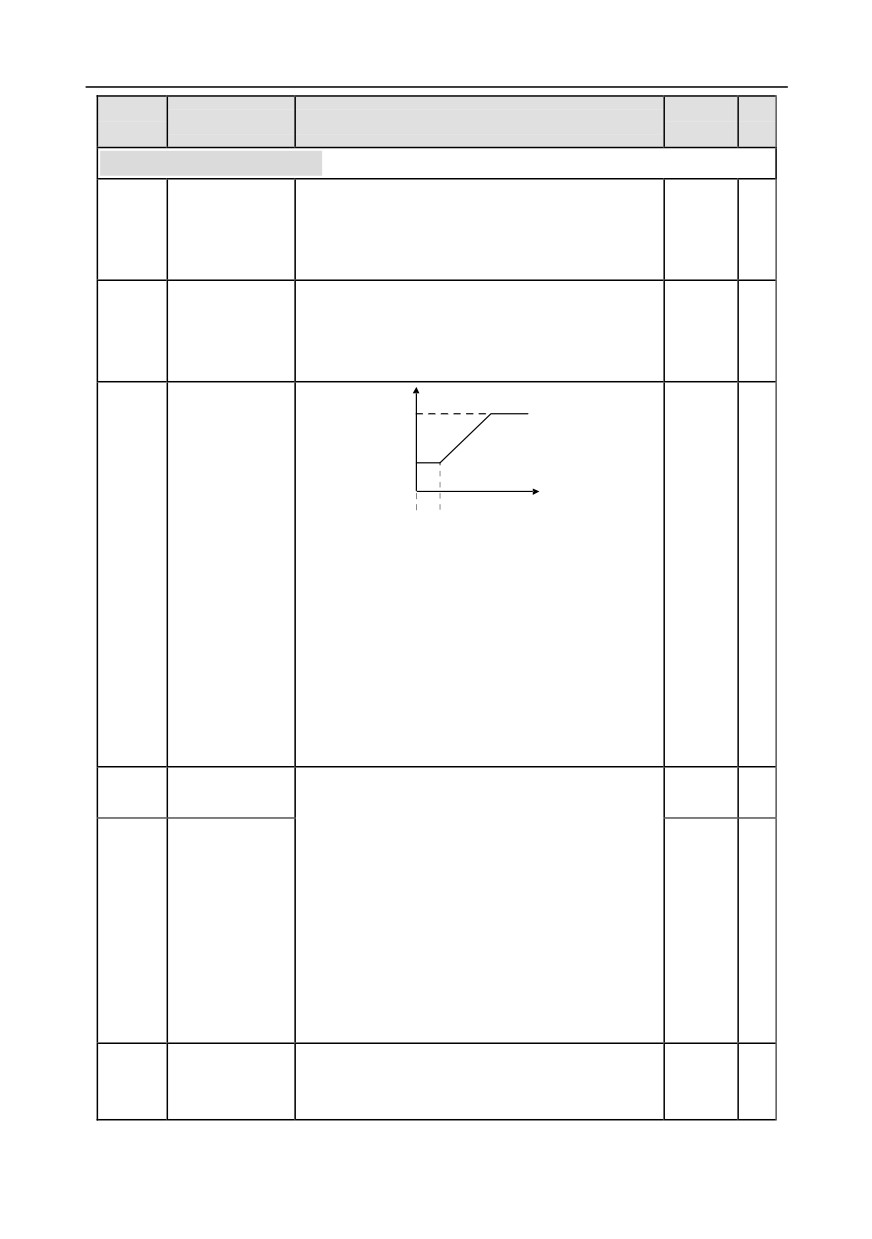
Starting frequency of direct startup is the initial
Starting
frequency when the inverter starts. See P01.02 (hold
P01.01
frequency of
0.50Hz
◎
time of starting frequency) for details.
direct start
Setting range: 0.00-50.00Hz
Output frequency
fmax
F1 set by P01.01
f1
T1 set by P01.02
T
t1
A proper starting frequency can increase the torque
Hold time of
during startup. Within the hold time of starting
P01.02
starting
0.0s
◎
frequency, the output frequency of inverter is the
frequency
starting frequency, and then it runs from the starting
frequency to the target frequency, if the target
frequency
(frequency command) is below the
starting frequency, the inverter will be standby rather
than running. The starting frequency value is
unlimited by the lower limit frequency.
Setting range: 0.0-50.0s
DC brake current
During starting, the inverter will first perform DC
P01.03
0.0%
◎
before start
brake based on the set DC brake current before
startup, and then it will accelerate after the set DC
brake time before startup elapses. If the set DC
brake time is 0, DC brake will be invalid.
The larger the DC brake current, the stronger the
DC brake time
P01.04
brake force. The DC brake current before startup
0.00s
◎
before start
refers to the percentage relative to rated inverter
current.
Setting range of P01.03: 0.0-100.0%
Setting range of P01.04: 0.00-50.00s
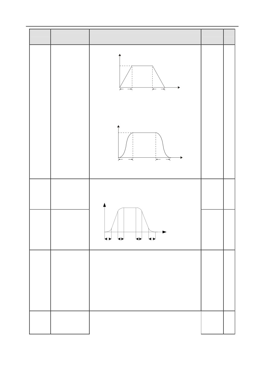
This function code is used to select the frequency
Acceleration/dec
P01.05
variation mode during starting and running.
0
◎
eleration mode
0: Straight line; the output frequency increases or
-129-
Chapter 6
Function
Default
Modi
Name
Detailed parameter description
code
value
fy
decreases in straight line;
Output frequency f
fmax
Time t
t1
t2
1: S curve; the output frequency increases or
decreases in S curve;
S curve is generally used in cases where smooth
start/stop is required, eg, elevator, conveyer belt, etc.
Output frequency f
fmax
Time t
t1
t2
Note: When set to 1, it is required to set P01.06,
P01.07, P01.27 and P01.28 accordingly.
Time of starting
The curvature of S curve is determined by
section of
acceleration range and acceleration and
P01.06
0.1s
◎
acceleration S
deceleration time.
Output frequency f
curve
Time of ending
t1=P01.06
t2=P01.07
section of
t3=P01.27
Time t
t4=P01.28
P01.07
0.1s
◎
acceleration S
t1
t2
t3
t4
curve
Setting range: 0.0-50.0s
0: Decelerate to stop; after stop command is valid,
the inverter lowers output frequency based on the
deceleration mode and the defined deceleration
time, after the frequency drops to the stop speed
P01.08
Stop mode
0
○
(P01.15), the inverter stops.
1: Coast to stop; after stop command is valid, the
inverter stops output immediately, and the load
coasts to stop as per mechanical inertia.
Starting
Starting frequency of DC brake after stop; during
P01.09
frequency of DC
decelerating to stop, when this frequency is reached,
0.00Hz
○
brake after stop
DC brake will be performed after stop.
-130-
Chapter 6
Function
Default
Modi
Name
Detailed parameter description
code
value
fy
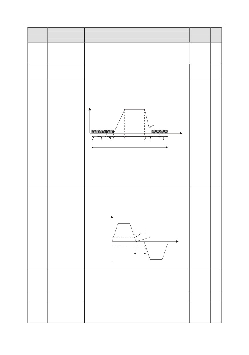
Waiting time of
Demagnetization time (waiting time of DC brake after
P01.10
DC brake after
stop): Before the DC brake, the inverter will block
0.00s
○
stop
output, and after the demagnetization time elapses,
DC brake current
DC brake will start. This function is used to prevent
P01.11
0.0%
○
of stop
overcurrent fault caused by DC brake during high
speed.
DC brake current after stop: it means the DC brake
force applied, the larger the current, the stronger the
DC brake effect.
P01.09
DC brake time of
Time t
P01.12
Acceleration Constant speed
P13.15
0.00s
○
stop
P01.23
P13.14
P01.04
Deceleration
P01.10
P01.12
In running
Setting range of P01.09: 0.00Hz-P00.03 (max.
output frequency)
Setting range of P01.10: 0.00-30.00s
Setting range of P01.11: 0.0-100.0%
Setting range of P01.12: 0.0-50.0s
This function code refers to the transition time of the
threshold set by P01.14 during setting
forward/reverse rotation of the inverter, as shown
below.
Output frequency f
Deadzone time of
Forward
P01.13
forward/reverse
Switch over after
0.0s
○
starting frequency
rotation
Starting
Switch over after
frequency
zero frequency
Time t
Deadzone
Reverse
time
Setting range: 0.0-3600.0s
Forward/reverse
0: Switch over after zero frequency
P01.14
rotation
1: Switch over after starting frequency
0
◎
switch-over mode 2: Switch over after passing stop speed and delay
P01.15
Stop speed
0.00-100.00Hz
0.50Hz
◎
0: Set value of speed (the only detection mode valid
Stop speed
P01.16
in SVPWM mode)
0
◎
detection mode
1: Detection value of speed
-131-
Chapter 6
Function
Default
Modi
Name
Detailed parameter description
code
value
fy
Stop speed
P01.17
0.00-100.00s
0.50s
◎
detection time
When the running command channel is controlled by
terminals, the system will detect running terminal
state automatically during power up.
0: Terminal running command is invalid during power
up. The inverter will not run during power up even if
the running command terminal is detected to be
Running
valid, and the system is in running protection state.
protection of
P01.18
The inverter will run only after this terminal is
0
○
power-on
cancelled and enabled again.
terminal
1: Terminal running command is valid during power
up. The system will start the inverter automatically
after initialization is done if the running command
terminal is detected to be valid during power up.
Note: This function must be set with caution,
otherwise, serious consequences may occur.
This function code is used to set the running state of
inverter when the set frequency is below lower limit
frequency.
Action selection
0: Run in lower limit of the frequency
when the running
1: Stop
frequency is
2: Sleep
P01.19
below lower limit
0
◎
When the set frequency is below lower limit
(lower limit
frequency, the inverter coasts to stop; when the set
should be larger
frequency is above lower limit again and continues to
than 0)
be so after the time set by P01.20 elapses, the
inverter will be restored to running state
automatically.
This function code is used to set the sleep delay.
When the running frequency of inverter is below the
Wake-up-from-sl
lower limit frequency, the inverter enters sleep state;
P01.20
0.0s
○
eep delay
when the set frequency is above the lower limit again
and continues to be so after the time set by P01.20
elapses, the inverter will run automatically.
-132-
Chapter 6
Function
Default
Modi
Name
Detailed parameter description
code
value
fy
Output frequency f
t1<t2, the inverter does not run
t1+t2=t3, the inverter runs
t3=P01.20
t1
t2
t3
Time t
Run
Sleep
Run
Setting range: 0.0-3600.0s (valid when P.01.19 is 2)
This function code sets the automatic running of the
inverter at next power-on after power down.
Restart after
0: Disabled restart
P01.21
0
○
power cut
1: Enable restart, namely the inverter will run
automatically after the time set by P01.22 elapses if
the starting conditions are met.
This function code sets the waiting time before
automatically running at next power-on after power
down.
Output frequency
t1=P01.22
Waiting time of
t2=P01.23
P01.22
restart after
1.0s
○
power cut
t1
t2
t
Running
Running Power off
Power on
Setting range: 0.0-3600.0s (valid when P01.21 is 1)
This function code sets the delay of the inverter’s
wake-up-from-sleep after running command is given,
P01.23
Start delay
the inverter will start to run and output after the time
0.0s
○
set by P01.23 elapses to realize brake release.
Setting range: 0.0-600.0s
P01.24
Stop speed delay
0.0-600.0s
0.0s
○
0: No voltage output
Open-loop 0Hz
P01.25
1: With voltage output
0
○
output selection
2: Output as per DC brake current of stop
Deceleration time
P01.26
of
0.0-60.0s
2.0s
○
emergency-stop
Time of starting
section of
P01.27
0.0-50.0s
0.1s
◎
deceleration S
curve
-133-
Chapter 6
Function
Default
Modi
Name
Detailed parameter description
code
value
fy
Time of ending
section of
P01.28
0.0-50.0s
0.1s
◎
deceleration S
curve
Short-circuit
When the inverter starts in direct start mode
P01.29
0.0%
○
brake current
(P01.00=0), set P01.30 to a non-zero value to enter
Hold time of
short-circuit brake.
P01.30
short-circuit
During stop, if the running frequency of inverter is
0.00s
○
brake at startup
below the starting frequency of brake after stop, set
P01.31 to a non-zero value to enter short-circuit
brake after stop, and then carry out DC brake in the
Hold time of
time set by P01.12 (refer to P01.09-P01.12).
P01.31
short-circuit
0.00s
○
Setting range of P01.29: 0.0-150.0% (inverter)
brake at stop
Setting range of P01.30: 0.0-50.0s
Setting range of P01.31: 0.0-50.0s
P01.32-
Reserved
0-65535
0
●
P01.34
variables
P02 group Parameters of motor 1
0: Asynchronous motor
P02.00
Type of motor 1
0
◎
1: Synchronous motor
Rated power of
Depend
P02.01
asynchronous
0.1-3000.0kW
◎
on model
motor 1
Rated frequency
P02.02
of asynchronous
0.01Hz-P00.03 (max. output frequency)
50.00Hz
◎
motor 1
Rated speed of
Depend
P02.03
asynchronous
1-36000rpm
◎
on model
motor 1
Rated voltage of
Depend
P02.04
asynchronous
0-1200V
◎
on model
motor 1
Rated current of
Depend
P02.05
asynchronous
0.8-6000.0A
◎
on model
motor 1
Stator resistance
Depend
P02.06
of asynchronous
0.001-65.535Ω
○
on model
motor 1
-134-
Chapter 6
Function
Default
Modi
Name
Detailed parameter description
code
value
fy
Rotor resistance
Depend
P02.07
of asynchronous
0.001-65.535Ω
○
on model
motor 1
Leakage
inductance of
Depend
P02.08
0.1-6553.5Mh
○
asynchronous
on model
motor 1
Mutual
inductance of
Depend
P02.09
0.1-6553.5Mh
○
asynchronous
on model
motor 1
No-load current
Depend
P02.10
of asynchronous
0.1-6553.5A
○
on model
motor 1
Magnetic
saturation
coefficient 1 of
P02.11
0.0-100.0%
80.0%
○
iron core of
asynchronous
motor 1
Magnetic
saturation
coefficient 2 of
P02.12
0.0-100.0%
68.0%
○
iron core of
asynchronous
motor 1
Magnetic
saturation
coefficient 3 of
P02.13
0.0-100.0%
57.0%
○
iron core of
asynchronous
motor 1
Magnetic
saturation
coefficient 4 of
P02.14
0.0-100.0%
40.0%
○
iron core of
asynchronous
motor 1
-135-
Chapter 6
Function
Default
Modi
Name
Detailed parameter description
code
value
fy
Rated power of
Depend
P02.15
synchronous
0.1-3000.0KW
◎
on model
motor 1
Rated frequency
P02.16
of synchronous
0.01Hz-P00.03 (max. output frequency)
50.00Hz
◎
motor 1
Number of pole
pairs of
P02.17
1-128
2
◎
synchronous
motor 1
Rated voltage of
Depend
P02.18
synchronous
0-1200V
◎
on model
motor 1
Rated current of
Depend
P02.19
synchronous
0.8-6000.0A
◎
on model
motor 1
Stator resistance
Depend
P02.20
of synchronous
0.001-65.535Ω
○
on model
motor 1
Direct-axis
inductance of
Depend
P02.21
0.01-655.35Mh
○
synchronous
on model
motor 1
Quadrature-axis
inductance of
Depend
P02.22
0.01-655.35Mh
○
synchronous
on model
motor 1
Counter-emf
constant of
P02.23
0-10000
300
○
synchronous
motor 1
Initial pole
position of
P02.24
synchronous
0x0000-0xFFFF
0
●
motor 1
(reserved)
Identification
P02.25
0%-50% (rated motor current)
10%
●
current of
-136-
Chapter 6
Function
Default
Modi
Name
Detailed parameter description
code
value
fy
synchronous
motor 1
(reserved)
0: No protection
1: Common motor (with low-speed compensation).
As the cooling effect of common motor will be
degraded in low speed, the corresponding electronic
thermal protection value should also be adjusted
Overload
properly, the low compensation here means to lower
P02.26
protection of
the overload protection threshold of the motor whose
2
◎
motor 1
running frequency is below 30Hz.
2: Frequency-variable motor
(without low speed
compensation). As the cooling effect of
frequency-variable motor is not affected by the
rotating speed, there is no need to adjust the
protection value during low speed running.
Motor overload multiples M=Iout/(In×K)
In is rated motor current, lout is inverter output
current, K is motor overload protection coefficient.
The smaller the K, the larger the value of M, and the
easier the protection.
M=116%: protection will be applied when motor
Overload
overloads for 1h; M=200%: protection will be applied
protection
when motor overloads for 60s; M>=400%: protection
P02.27
100.0%
○
coefficient of
will be applied immediately.
Time t
motor 1
1h
1m
Motor overload multiple
116%
200 %
Setting range: 20.0%-120.0%
Power display
This function adjusts the power display value of
calibration
motor 1 only, and it does not affect the control
P02.28
1.00
○
coefficient of
performance of the inverter.
motor 1
Setting range: 0.00-3.00
0: Display as per motor type; under this mode, only
Parameter
P02.29
parameters related to current motor type will be
0
○
display of motor 1
displayed.
-137-
Chapter 6
Function
Default
Modi
Name
Detailed parameter description
code
value
fy
1: Display all; under this mode, all the motor
parameters will be displayed.
System inertia of
P02.30
0-30.000kgm2
0
○
motor 1
P02.31-
Reserved
0-65535
0
○
P02.32
variables
P03 group Vector control of motor 1
Speed loop
Parameters of P03.00-P03.05 fit for vector control
P03.00
20.0
○
proportional gain 1
mode only. Below P03.02, speed loop PI parameter
Speed loop
is P03.00 and P03.01; above P03.06, speed loop PI
P03.01
0.200s
○
integral time 1
parameter is P03.03 and P03.04; in between, PI
Switch low point
parameter is obtained by linear variation between
P03.02
5.00Hz
○
frequency
two groups of parameters, as shown below.
PI parameter
Speed loop
P03.00,P03.01
P03.03
proportional gain
20.0
○
2
P03.03,P03.04
Speed loop
P03.04
Output frequency f
0.200s
○
integral time 2
P03.02
P03.05
The speed loop dynamic response characteristics of
vector control can be adjusted by setting the
proportional coefficient and integral time of speed
regulator. Increase proportional gain or decrease
integral time can accelerate dynamic response of
speed loop, however, if the proportional gain is too
large or integral time is too small, system oscillation
and overshoot may occur; if proportional gain is too
small, stable oscillation or speed offset may occur.
Switch over high
Speed loop PI parameter is closely related to the
P03.05
10.00Hz
○
point frequency
system inertial, users should make adjustment
based on default PI parameter according to different
load characteristics to fulfill different needs.
Setting range of P03.00:0.0-200.0;
Setting range of P03.01: 0.000-10.000s
Setting range of P03.02: 0.00Hz-P03.05
Setting range of P03.03: 0.0-200.0
Setting range of P03.04: 0.000-10.000s
Setting range of P03.05: P03.02-P00.03
(max.
output frequency)
-138-
Chapter 6
Function
Default
Modi
Name
Detailed parameter description
code
value
fy
Speed loop
P03.06
0-8 (corresponds to 0-2^8/10ms)
0
○
output filter
Vector control
slip
P03.07
compensation
100%
○
Slip compensation coefficient is used to adjust the
coefficient
slip frequency of vector control to improve speed
(motoring)
control precision. This parameter can be used to
Vector control
control speed offset.
slip
Setting range: 50-200%
P03.08
compensation
100%
○
coefficient
(generating)
Current loop
Note:
P03.09
proportional
1. These two parameters are used to adjust PI
1000
○
coefficient P
parameters of current loop; it affects dynamic
response speed and control precision of the system
directly. The default value needs no adjustment
under common conditions;
Current loop
2. Fit for SVC mode 0 (P00.00=0) and VC mode
P03.10
integral
(P00.00=3);
1000
○
coefficient I
3. The value of this function code will be updated
automatically after parameter autotuning of
synchronous motor is done.
Setting range: 0-65535
0-1: Set via keypad (P03.12)
2: Set via AI1 (100% corresponds to three times of
rated motor current)
3: Set via AI2 (the same as above)
4: Set via AI3 (the same as above)
5: Set via pulse frequency HDIA (the same as
above)
Torque setup
P03.11
6: Set via multi-step torque (the same as above)
0
○
mode selection
7: Set via MODBUS communication (the same as
above)
8: Set via PROFIBUS/CANopen/DeviceNet
communication (the same as above)
9: Set via Ethernet communication (the same as
above)
10: Set via pulse frequency HDIB (the same as
-139-
Chapter 6
Function
Default
Modi
Name
Detailed parameter description
code
value
fy
above)
11: Set via EtherCat/Profinet communication
12: Set via PLC
Torque set by
P03.12
-300.0%-300.0% (rated motor current)
20.0%
○
keypad
Torque reference
P03.13
0.000-10.000s
0.010s
○
filter time
0: Keypad (P03.16)
1: AI1 (100% corresponds to max. frequency)
2: AI2 (the same as above)
3: AI3 (the same as above)
4: Pulse frequency HDIA (the same as above)
Source of upper
5: Multi-step (the same as above)
limit frequency
6: MODBUS communication (the same as above)
P03.14
setup of forward
0
○
7: PROFIBUS /CANopen/ DeviceNet communication
rotation in torque
(the same as above)
control
8: Ethernet communication (the same as above)
9: Pulse frequency HDIB (the same as above)
10: EtherCat/Profinet communication
11: PLC
12: Reserved
0: Keypad (P03.17)
1: AI1 (100% corresponds to max. frequency)
2: AI2 (the same as above)
3: AI3 (the same as above)
4: Pulse frequency HDIA (the same as above)
5: Multi-step (the same as above)
Source of upper
6: MODBUS communication (the same as above)
limit frequency
7: PROFIBUS /CANopen/ DeviceNet communication
P03.15
setup of reverse
0
○
(the same as above)
rotation in torque
8: Ethernet communication (the same as above)
control
9: Pulse frequency HDIB (the same as above)
10: EtherCat/Profinet communication
11: PLC
12: Reserved
Note: Source
1-11,
100% relative to the max.
frequency
Keypad limit
This function code is used to set frequency limit.
P03.16
50.00Hz
○
value of upper
100% corresponds to the max. frequency. P03.16
-140-
Chapter 6
Function
Default
Modi
Name
Detailed parameter description
code
value
fy
limit frequency of
sets the value when P03.14=1; P03.17 sets the
forward rotation
value when P03.15=1.
in torque control
Setting range:
0.00Hz-P00.03
(max. output
Max. output
frequency)
P03.17
50.00Hz
○
frequency
0: Keypad (P03.20)
1: AI1 (100% relative to three times of motor current)
2: AI2 (the same as above)
3: AI3 (the same as above)
4: Pulse frequency HDIA (the same as above)
Source of upper
5: MODBUS communication (the same as above)
limit setup of the
P03.18
6: PROFIBUS/CANopen/DeviceNet communication
0
○
torque during
(the same as above)
motoring
7: Ethernet communication (the same as above)
8: Pulse frequency HDIB (the same as above)
9: EtherCat/Profinet communication
10: PLC
11: Reserved
0: Keypad (P03.21)
1: AI1 (100% relative to three times of motor current)
2: AI2 (the same as above)
3: AI3 (the same as above)
4: Pulse frequency HDIA (the same as above)
Source of upper
5: MODBUS communication (the same as above)
P03.19
limit setup of
6: PROFIBUS/CANopen/DeviceNet communication
0
○
brake torque
(the same as above)
7: Ethernet communication (the same as above)
8: Pulse frequency HDIB (the same as above)
9: EtherCat/Profinet communication
10: PLC
11: Reserved
Set upper limit of
the torque when
P03.20
180.0%
○
motoring via
This function code is used to set torque limit.
keypad
Setting range: 0.0-300.0% (rated motor current)
Set upper limit of
P03.21
brake torque via
180.0%
○
keypad
-141-
Chapter 6
Function
Default
Modi
Name
Detailed parameter description
code
value
fy
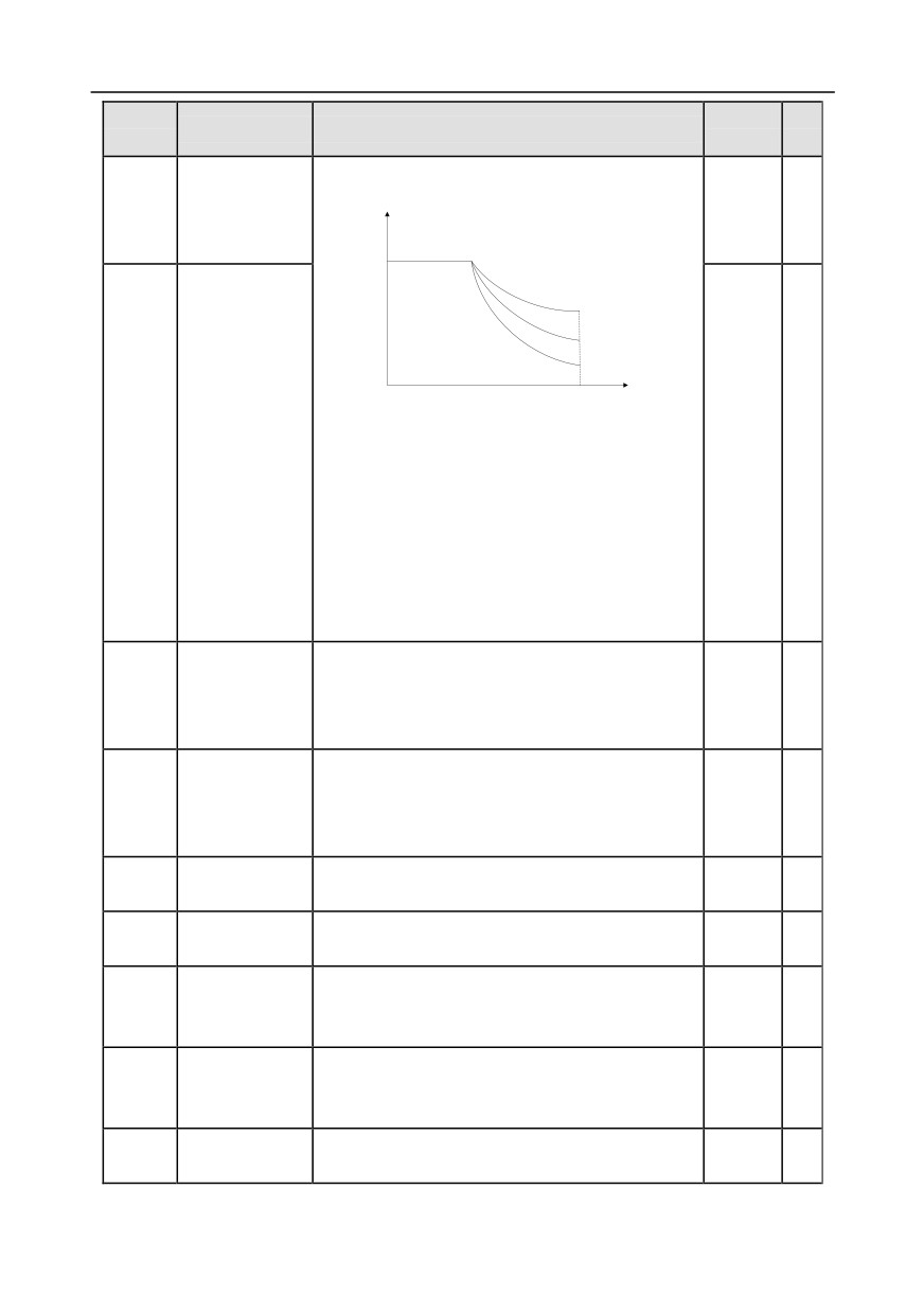
Flux-weakening
Used when asynchronous motor is in flux-weakening
coefficient of
control.
P03.22
0.3
○
constant-power
T
zone
Flux-weakening
coefficient of motor
0.1
1.0
2.0
f
Min. flux-weakening limit of motor
Min.
P03.22 and P03.23 are valid during constant power.
flux-weakening
When motor speed is above rated speed, motor
P03.23
point of
20%
○
enters flux-weakening running state. The
constant-power
flux-weakening control coefficient can change the
zone
flux-weakening curvature, the larger the coefficient,
the steeper the curve, the smaller the coefficient, the
smoother the curve.
Setting range of P03.22: 0.1-2.0
Setting range of P03.23: 10%-100%
P03.24 sets the max. output voltage of the inverter,
which is the percentage of rated motor voltage. This
P03.24
Max. voltage limit
100.0%
○
value should be set according to field conditions.
Setting range:0.0-120.0%
Carry out motor pre-exciting during starting to build a
magnetic field inside the motor to improve the torque
P03.25
Pre-exciting time
0.300s
○
characteristics of motor during starting.
Setting range: 0.000-10.000s
Flux-weakening
P03.26
0-8000
1000
○
proportional gain
Vector control
0: Display as per actual value
P03.27
0
○
speed display
1: Display as per the set value
Static friction
P03.28
compensation
0.0-100.0%
0.0%
○
coefficient
Corresponding
P03.29
frequency point
0.50- P03.31
1.00Hz
○
of static friction
High speed
P03.30
0.0-100.0%
0.0%
○
friction
-142-
Chapter 6
Function
Default
Modi
Name
Detailed parameter description
code
value
fy
compensation
coefficient
Corresponding
frequency of high
P03.31
P03.29-400.00Hz
50.00Hz
○
speed friction
torque
Torque control
0:Disable
P03.32
0
◎
enable
1:Enable
P03.33-
Reserved
0-65535
0
●
P03.35
variables
Speed loop
P03.36
0.00-10.00s
0.00s
○
differential gain
High-frequency
current loop
P03.37
Under closed-loop vector control mode (P00.00=3)
1000
○
proportional
and P03.39, the current loop PI parameters are
coefficient
P03.09 and P03.10; above P03.39, the PI
High-frequency
parameters are P03.37 and P03.38.
current loop
P03.38
Setting range of P03.37: 0-20000
1000
○
integral
Setting range of P03.38: 0-20000
coefficient
Setting range of P03.39:
0.0-100.0% (relative to
Current loop
max. frequency)
P03.39
high-frequency
100.0%
○
switch-over point
Inertia
0: Disable
P03.40
compensation
0
○
1: Enable
enable
Upper limit of
Limit the max. inertia compensation torque to
inertia
prevent inertia compensation torque from being too
P03.41
10.0%
○
compensation
large.
torque
Setting range: 0.0-150.0% (rated motor torque)
Inertia
Filter times of inertia compensation torque, used to
P03.42
compensation
smooth inertia compensation torque.
7
○
filter times
Setting range: 0-10
Due to friction force, it is required to set certain
Inertia
identification torque for the inertia identification to be
P03.43
identification
10.0%
○
performed properly.
torque value
0.0-100.0% (rated motor torque)
P03.44
Enable inertia
0: No operation
0
◎
-143-
Chapter 6
Function
Default
Modi
Name
Detailed parameter description
code
value
fy
identification
1: Start identification
P03.45-
Reserved
0-65535
0
●
P03.46
variables
P04 group V/F control
This group of function code defines the V/F curve of
motor
1 to satisfy different load characteristics
needs.
0: Straight V/F curve; fit for constant-torque load
1: Multi-point V/F curve
2: Torque down V/F curve (1.3th order)
3: Torque down V/F curve (1.7th order)
4: Torque down V/F curve (2.0nd order)
Curve 2-4 are suitable for torque-variable load of fan
pump and similar equipment. Users can make
adjustment based on load characteristics to achieve
optimal energy-saving effect.
V/F curve setup
5: Customized V/F
(V/F separation); under this
P04.00
0
◎
of motor 1
mode, V is separated from f. Users can adjust f
through the frequency reference channel set by
P00.06 to change the curve characteristic, or adjust
V through the voltage reference channel set by
P04.27 to change the curve characteristics.
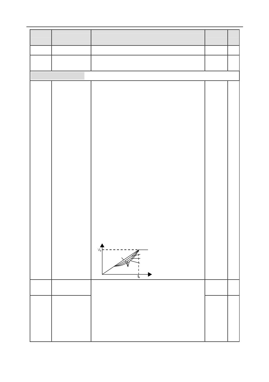
Note: The Vb in the figure below corresponds to
rated motor voltage, and fb corresponds to rated
motor frequency.
Output voltage
Torque step-down V/F curve (1.3th order)
Linear type
Torque step-down V/F curve (1.7th order)
Torque step-down V/F curve (2.0nd order)
Square type
Output frequency
Torque boost of
In order to compensate for low-frequency torque
P04.01
0.0%
○
motor 1
characteristics, users can make some boost
compensation to the output voltage. P04.01 is
relative to the max. output voltage Vb.
Motor 1 torque
P04.02 defines the percentage of cut-off frequency
P04.02
20.0%
○
boost cut-off
of manual torque boost to the rated motor frequency
fb. Torque boost can improve the low-frequency
torque characteristics of V/F.
-144-
Chapter 6
Function
Default
Modi
Name
Detailed parameter description
code
value
fy
Users should select torque boost based on the load,
eg, larger load requires larger torque boost,
however, if the torque boost is too large, the motor
will run at over-excitation, which will cause increased
output current and motor heat-up, thus degrading the
efficiency.
When torque boost is set to 0.0%, the inverter is
automatic torque boost.
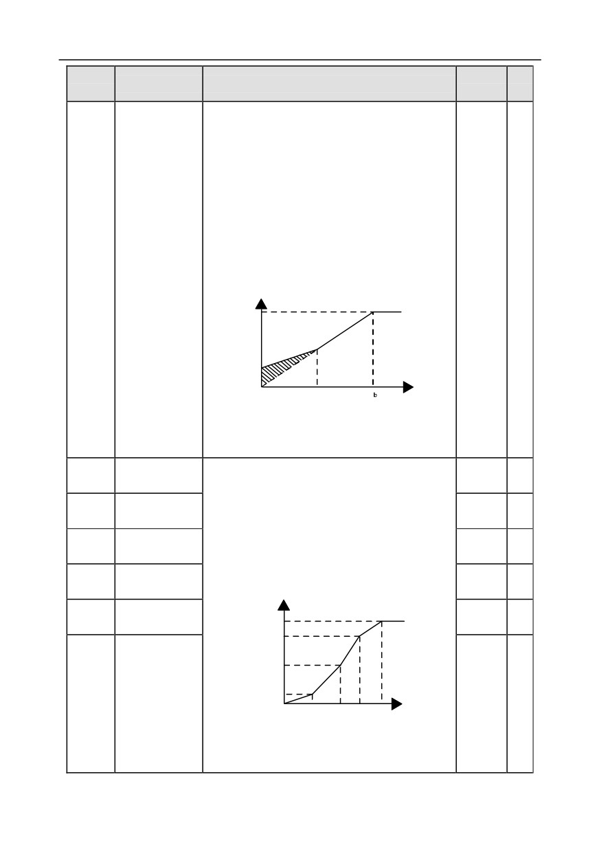
Torque boost cut-off threshold: Below this frequency
threshold, the torque boost is valid, exceeding this
threshold will nullify torque boost.
Output voltage
b
v
v
boost
Output
frequency
f
Cut-off
f
Setting range of P04.01: 0.0%: (automatic) 0.1%-
10.0%
Setting range of P04.02: 0.0%-50.0%
V/F frequency
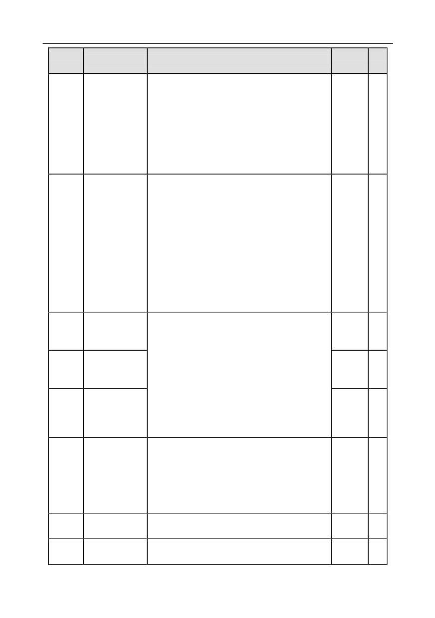
When P04.00 =1 (multi-point V/F curve), users can
P04.03
0.00Hz
○
point 1 of motor 1
set V/F curve via P04.03-P04.08.
V/F voltage point
V/F curve is usually set according to the
P04.04
00.0%
○
1 of motor 1
characteristics of motor load.
V/F frequency
Note: V1<V2<V3, f1<f2<f3. If low-frequency voltage
P04.05
0.00Hz
○
point 2 of motor 1
is set too high, motor overheat or burnt-down may
V/F voltage point
occur, and overcurrent stall or overcurrent protection
P04.06
0.0%
○
2 of motor 1
may occur to the inverter.
V/F frequency
Output voltage
P04.07
100.0% Vb
0.00Hz
○
point 3 of motor 1
V3
V2
Output
V1
frequency(Hz)
V/F voltage point
P04.08
00.0%
○
f1
f2
f3
fb
3 of motor 1
Setting range of P04.03: 0.00Hz-P04.05
Setting range of P04.04: 0.0%-110.0% (rated
voltage of motor 1)
-145-
Chapter 6
Function
Default
Modi
Name
Detailed parameter description
code
value
fy
Setting range of P04.05: P04.03-P04.07
Setting range of P04.06: 0.0%-110.0% (rated
voltage of motor 1)
Setting range of P04.07: P04.05-P02.02 (rated
frequency of motor 1) or P04.05- P02.16 (rated
frequency of motor 1)
Setting range of P04.08: 0.0%-110.0% (rated
voltage of motor 1)
This function code is used to compensate for the
motor speed changes occurred during load variation
in SVPWM control mode, thus improving the rigidity
of mechanical characteristics of motor. Rated slip
V/F slip
frequency of the motor should be calculated.
P04.09
compensation
△f=fb-n×p/60
0.0%
○
gain of motor 1
of which: fb is rated motor frequency, corresponds to
P02.02; n is rated motor speed, corresponds to
P02.03; p is the number of motor pole pairs. 100%
corresponds to the rated slip frequency of motor △f.
Setting range: 0.0-200.0%
Low-frequency
Under SVPWM control mode, the motor, especially
P04.10
oscillation control
the large-power motor may experience current
10
○
factor of motor 1
oscillation during certain frequencies, which may
High-frequency
lead to unstable motor operation, or even inverter
P04.11
oscillation control
overcurrent, users can adjust these two parameters
10
○
factor of motor 1
properly to eliminate such phenomenon.
Setting range of P04.10: 0-100
Oscillation
Setting range of P04.11: 0-100
P04.12
control threshold
30.00Hz
○
Setting range of P04.12: 0.00Hz-P00.03 (max.
of motor 1
output frequency)
0: Straight V/F curve;
1: Multi-point V/F curve
V/F curve setup
2: Torque-down V/F curve (1.3th order)
P04.13
0
◎
of motor 2
3: Torque-down V/F curve (1.7th order)
4: Torque-down V/F curve (2.0nd order)
5: Customize V/F (V/F separation)
Torque boost of
P04.14
0.0%: (automatic) 0.1%-10.0%
0.0%
○
motor 2
Motor 2 torque
P04.15
0.0%-50.0% (relative to rated frequency of motor 2)
20.0%
○
boost cut-off
-146-
Chapter 6
Function
Default
Modi
Name
Detailed parameter description
code
value
fy
V/F frequency
P04.16
0.00Hz- P04.18
0.00Hz
○
point 1 of motor 2
V/F voltage point
P04.17
0.0%-110.0% (rated voltage of motor 2)
00.0%
○
1 of motor 2
V/F frequency
P04.18
P04.16- P04.20
0.00Hz
○
point 2 of motor 2
V/F voltage point
P04.19
0.0%-110.0% (rated voltage of motor 2)
00.0%
○
2 of motor 2
P04.18- P12.02 (rated frequency of asynchronous
V/F frequency
motor 2)
P04.20
0.00Hz
○
point 3 of motor 2
Or P04.18- P12.16 (rated frequency of synchronous
motor 2)
V/F voltage point
P04.21
0.0%-110.0% (rated motor voltage)
00.0%
○
3 of motor 2
V/F slip
P04.22
compensation
0.0-200.0%
0.0%
○
gain of motor 2
Low-frequency
P04.23
oscillation control
0-100
10
○
factor of motor 2
High-frequency
P04.24
oscillation control
0-100
10
○
factor of motor 2
Oscillation
P04.25
control threshold
0.00Hz-P00.03 (max. output frequency)
30.00Hz
○
of motor 2
0: No action
1: Automatic energy-saving operation
Energy-saving
P04.26
Under light-load state, the motor can adjust the
0
◎
run
output voltage automatically to achieve
energy-saving purpose
0: Keypad; output voltage is determined by P04.28
1: AI1
2: AI2
Channel of
P04.27
3: AI3
0
○
voltage setup
4: HDIA
5: Multi-step (the set value is determined by P10
group)
-147-
Chapter 6
Function
Default
Modi
Name
Detailed parameter description
code
value
fy
6: PID
7: MODBUS communication
8: PROFIBUS/CANopen/DeviceNet communication
9: Ethernet communication
10: HDIB
11: EtherCat/Profinet communication
12: PLC programmable card
13: Reserved
When the channel for voltage setup is set to
Set voltage value
"keypad", the value of this function code is digital
P04.28
100.0%
○
via keypad
voltage set value.
Setting range: 0.0%-100.0%
Voltage increase
Voltage increase time means the time needed from
P04.29
5.0s
○
time
outputting the min. voltage to accelerating to output
the max. voltage.
Voltage decrease
Voltage decrease time means the time needed from
P04.30
5.0s
○
time
outputting max. voltage to outputting the min. voltage
Setting range: 0.0-3600.0s
Output max.
Set the upper/lower limit value of output voltage.
P04.31
100.0%
◎
voltage
Vmax
t1=P04.29
t2=P04.30
V set
Vmin
Output min.
t1
t2
Time t
P04.32
0.0%
◎
voltage
Setting range of P04.31: P04.32-100.0% (rated
motor voltage)
Setting range of P04.32: 0.0%-P04.31
Flux-weakening
coefficient of
P04.33
1.00-1.30
1.00
○
constant-power
zone
VF pull-in current
P04.34
1 of synchronous
-100.0%-100.0% (rated motor current)
20.0%
○
motor
VF pull-in current
P04.35
2 of synchronous
-100.0%-100.0% (rated motor current)
10.0%
○
motor
VF pull-in current
P04.36
0.00Hz-P00.03 (max. output frequency)
50.00Hz
○
frequency
-148-
Chapter 6
Function
Default
Modi
Name
Detailed parameter description
code
value
fy
switch-over
threshold of
synchronous
motor
VF reactive
closed-loop
proportional
P04.37
0-3000
50
○
coefficient of
synchronous
motor
VF reactive
closed-loop
P04.38
integral time of
0-3000
30
○
synchronous
motor
VF reactive
closed-loop
P04.39
output limit of
0-16000
8000
○
synchronous
motor
Enable/disable IF
mode of
P04.40
0-1
0
◎
asynchronous
motor 1
IF current setting
P04.41
of asynchronous
0.0-200.0%
120.0%
○
motor 1
IF proportional
coefficient of
P04.42
0-5000
650
○
asynchronous
motor 1
IF integral
coefficient of
P04.43
0-5000
350
○
asynchronous
motor 1
IF mode cut-off
P04.44
frequency
0.00-20.00Hz
10.00Hz
○
threshold of
-149-
Chapter 6
Function
Default
Modi
Name
Detailed parameter description
code
value
fy
asynchronous
motor 1
Enable/disable IF
mode of
P04.45
0-1
0
◎
asynchronous
motor 2
IF current setting
P04.46
of asynchronous
0.0-200.0%
120.0%
○
motor 2
IF proportional
coefficient of
P04.47
0-5000
650
○
asynchronous
motor 2
IF integral
coefficient of
P04.48
0-5000
350
○
asynchronous
motor 2
IF mode cut-off
frequency
P04.49
threshold of
0.00-20.00Hz
10.00Hz
○
asynchronous
motor 2
Reserved
P04.50
0-65535
0
●
variables
Reserved
P04.51
0-65535
0
●
variables
P05 group Input terminals
0x00-0x11
Ones: HDIA input type
0: HDIA is high-speed pulse input
P05.00
HDI input type
1: HDIA is digital input
0
◎
Tens: HDIB input type
0: HDIB is high-speed pulse input
1: HDIB is digital input
Function of S1
0: No function
P05.01
1
◎
terminal
1: Forward running
Function of S2
2: Reverse running
P05.02
4
◎
terminal
3: 3-Wire control/Sin
-150-
Chapter 6
Function
Default
Modi
Name
Detailed parameter description
code
value
fy
Function of S3
4: Forward jogging
P05.03
7
◎
terminal
5: Reverse jogging
Function of S4
6: Coast to stop
P05.04
0
◎
terminal
7: Fault reset
Function of HDIA
8: Running pause
P05.05
0
◎
terminal
9: External fault input
10: Frequency increase (UP)
11: Frequency decrease (DOWN)
12: Clear frequency increase/decrease setting
13: Switch-over between setup A and setup B
14: Switch-over between combination setup
and
setup A
15: Switch-over between combination setup
and
setup B
16: Multi-step speed terminal 1
17: Multi-step speed terminal 2
18: Multi-step speed terminal 3
19: Multi-step speed terminal 4
20: Multi-step speed pause
21: Acceleration/deceleration time selection 1
22: Acceleration/deceleration time selection 2
23: Simple PLC stop reset
Function of HDIB
P05.06
24: Simple PLC pause
0
◎
terminal
25: PID control pause
26: Wobbling frequency pause
27: Wobbling frequency reset
28: Counter reset
29: Switch-over between speed control and torque
control
30: Acceleration/deceleration disabled
31: Counter trigger
32: Reserved
33: Clear frequency increase/decrease setting
temporarily
34: DC brake
35: Switch-over between motor 1 and motor 2
36: Command switches to keypad
37: Command switches to terminal
38: Command switches to communication
-151-
Chapter 6
Function
Default
Modi
Name
Detailed parameter description
code
value
fy
39: Pre-exciting command
40: Zero out power consumption quantity
41: Maintain power consumption quantity
42: Source of upper torque limit switches to keypad
43: Position reference point input (only S6, S7 and
S8 are valid)
44: Spindle orientation disabled
45: Spindle zeroing/local positioning zeroing
46: Spindle zero position selection 1
47: Spindle zero position selection 2
48: Spindle scale division selection 1
49: Spindle scale division selection 2
50: Spindle scale division selection 3
51: Position control and speed control switch-over
terminal
52: Pulse input disabled
53: Clear position deviation cleared
54: Switch over position proportional gain
55: Enable cyclic positioning of digital position
positioning
56: Emergency stop
57: Motor over-temperature fault input
58: Enable rigid tapping
59: Switches to V/F control
60: Switches to FVC control
61: PID polarity switch-over
62: Reserved
63: Enable servo
64: Limit of forward run
65: Limit of reverse run
66: Zero out encoder counting
67: Pulse increase
68: Enable pulse superimposition
69: Pulse decrease
70: Electronic gear selection
71-79: Reserved
Reserved
P05.07
0-65535
0
●
variables
P05.08
Polarity of input
This function code is used to set the polarity of input
0x000
○
-152-
Chapter 6
Function
Default
Modi
Name
Detailed parameter description
code
value
fy
terminal
terminals.
When the bit is set to 0, input terminal polarity is
positive;
When the bit is set to 1, input terminal polarity is
negative;
0x000-0x3F
Set S1-S4, filter time of HDI terminal sampling. In
cases where interference is strong, increase the
P05.09
Digital filter time
0.010s
○
value of this parameter to avoid mal-operation.
0.000-1.000s
0x000-0x3F (0: disable, 1: enable)
BIT0: S1 virtual terminal
BIT1: S2 virtual terminal
Virtual terminal
P05.10
BIT2: S3 virtual terminal
0x00
◎
setting
BIT3: S4 virtual terminal
BIT4: HDIA virtual terminal
BIT5: HDIB virtual terminal
This function code is used to set the 2/3 Wire control
mode.
0: 2-Wire control 1; integrate enabling function with
direction. This mode is the most popular dual-line
mode. Direction of motor rotation is determined by
the defined FWD/REV terminal command.
Running
FWD
REV
command
FWD
2/3 Wire control
K1
OFF
OFF
Stop
P05.11
0
◎
mode
Forward
REV
ON
OFF
running
K2
Reverse
OFF
ON
running
COM
ON
ON
Hold
1: 2-Wire control 2; separate enabling function with
direction. In this mode, the defined FWD is enabling
terminal, and the direction is determined by the state
of REV.
-153-
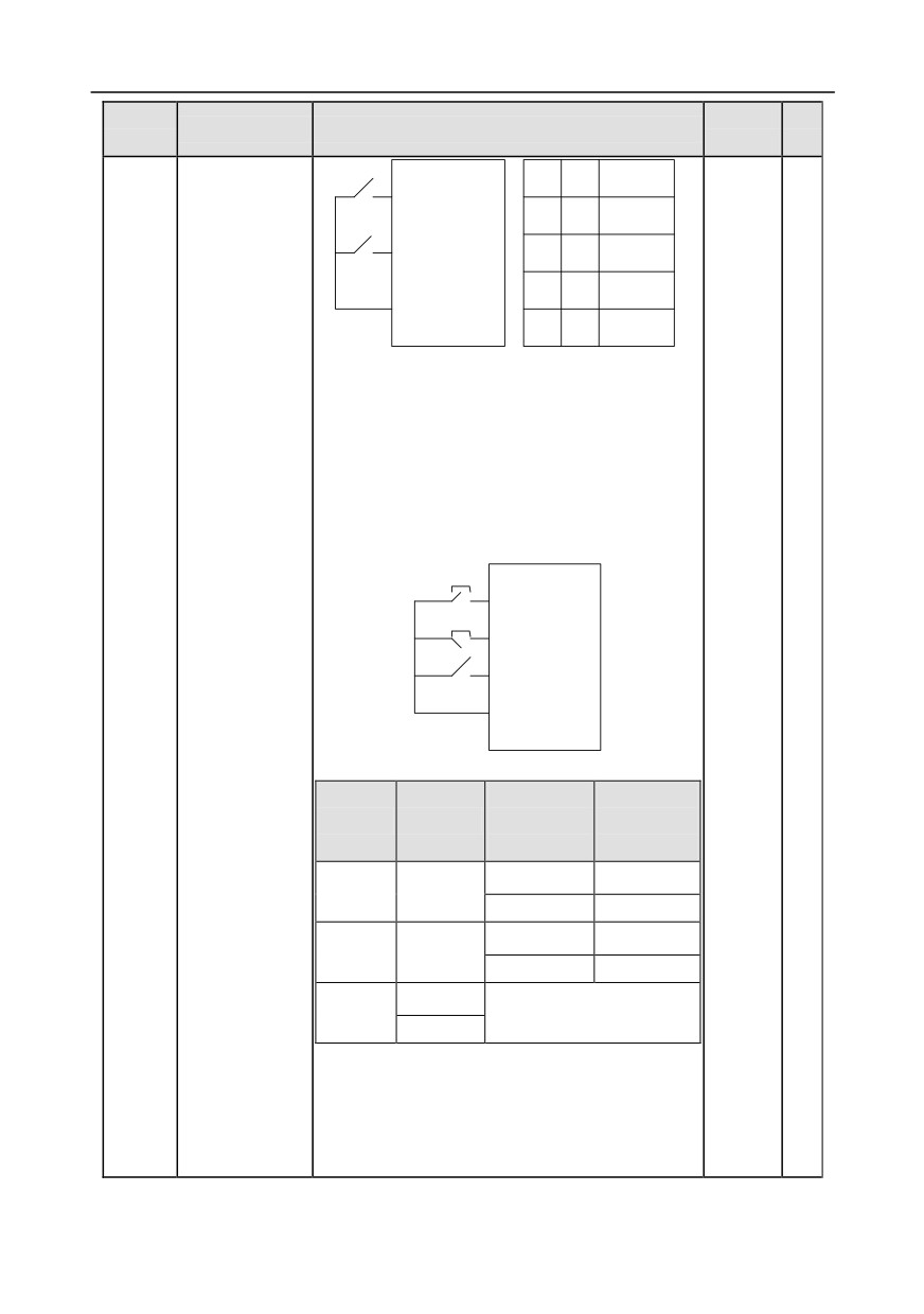
Chapter 6
Function
Default
Modi
Name
Detailed parameter description
code
value
fy
Running
FWD
REV
command
FWD
K1
OFF
OFF
Stop
Forward
REV
ON
OFF
running
K2
OFF
ON
Stop
COM
ON
ON
Reverse
running
2:
3-Wire control
1; This mode defines Sin as
enabling terminal, and the running command is
generated by FWD, the direction is controlled by
REV. During running, the Sin terminal should be
closed, and terminal FWD generates a rising edge
signal, then the inverter starts to run in the direction
set by the state of terminal REV; the inverter should
be stopped by disconnecting terminal Sin.
SB1
FWD
SB2
SIn
REV
K
COM
The direction control during running is shown below.
Previous
Current
Sln
REV
running
running
direction
direction
Forward
Reverse
ON
OFF→ON
Reverse
Forward
Reverse
Forward
ON
ON→OFF
Forward
Reverse
ON
ON→OFF
Decelerate to stop
OFF
Sln:
3-Wire control/Sin, FWD: Forward running,
REV: Reverse running
3:
3-Wire control
2; This mode defines Sin as
enabling terminal. The running command is
generated by FWD or REV, and they control the
-154-