Goodrive350 Series High-performance Multi-function Inver ter. Operation manual - page 3
Chapter 5
Function
Default
Name
Detailed parameter description
code
value
/Devicenet
3: Switch over by Ethernet
communication
4: Switch over by EtherCat/Profinet
communication
Tens: Motor switch-over during running
0: Disable switch-over during running
1: Enable switch-over during running
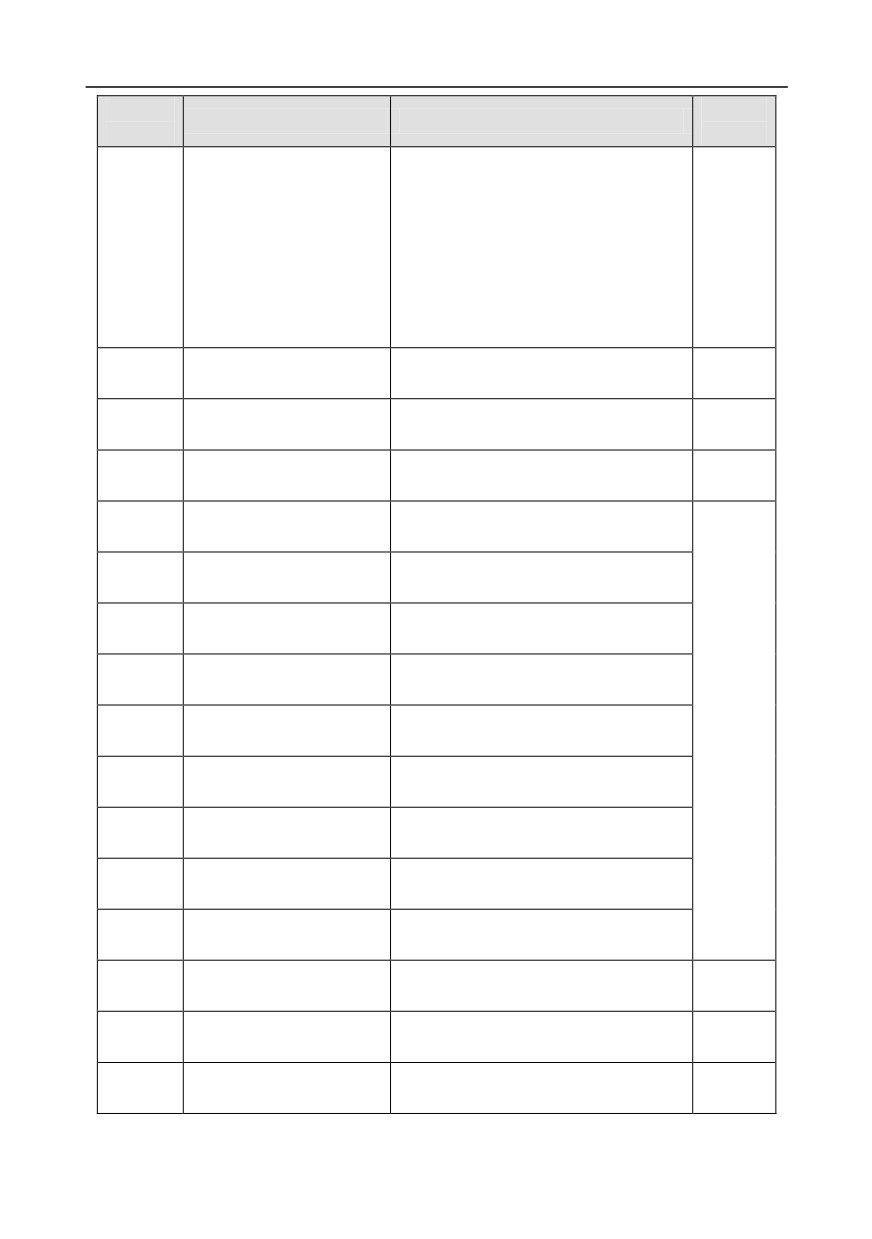
0: Asynchronous motor
P12.00
Type of motor 2
0
1: Synchronous motor
Rated power of
Depend
P12.01
0.1-3000.0kW
asynchronous motor 2
on model
Rated frequency of
P12.02
0.01Hz-P00.03 (max. output frequency)
50.00Hz
asynchronous motor 2
Rated speed of
P12.03
1-36000rpm
asynchronous motor 2
Rated voltage of
P12.04
0-1200V
asynchronous motor 2
Rated current of
P12.05
0.8-6000.0A
asynchronous motor 2
Stator resistance of
P12.06
0.001-65.535Ω
asynchronous motor 2
Rotor resistance of
Depend
P12.07
0.001-65.535Ω
asynchronous motor 2
on model
Leakage inductance of
P12.08
0.1-6553.5mH
asynchronous motor 2
Mutual inductance of
P12.09
0.1-6553.5mH
asynchronous motor 2
No-load current of
P12.10
0.1-6553.5A
asynchronous motor 2
Rated power of synchronous
P12.15
0.1-3000.0kW
motor 2
Rated frequency of
P12.16
0.01Hz-P00.03 (max. output frequency)
50.00Hz
synchronous motor 2
Number of pole pairs of
P12.17
1-50
2
synchronous motor 2
Rated voltage of
Depend
P12.18
0-1200V
synchronous motor 2
on model
-75-
Chapter 5
Function
Default
Name
Detailed parameter description
code
value
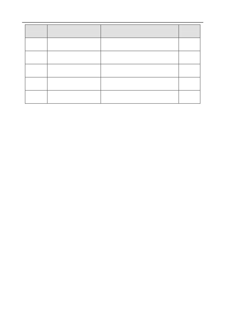
Rated current of
Depend
P12.19
0.8-6000.0A
synchronous motor 2
on model
Stator resistance of
Depend
P12.20
0.001-65.535Ω
synchronous motor 2
on model
Direct-axis inductance of
Depend
P12.21
0.01-655.35mH
synchronous motor 2
on model
Quadrature-axis inductance
Depend
P12.22
0.01-655.35mH
of synchronous motor 2
on model
Counter-emf constant of
P12.23
0-10000
300
synchronous motor 2
5.5.7 Start/stop control
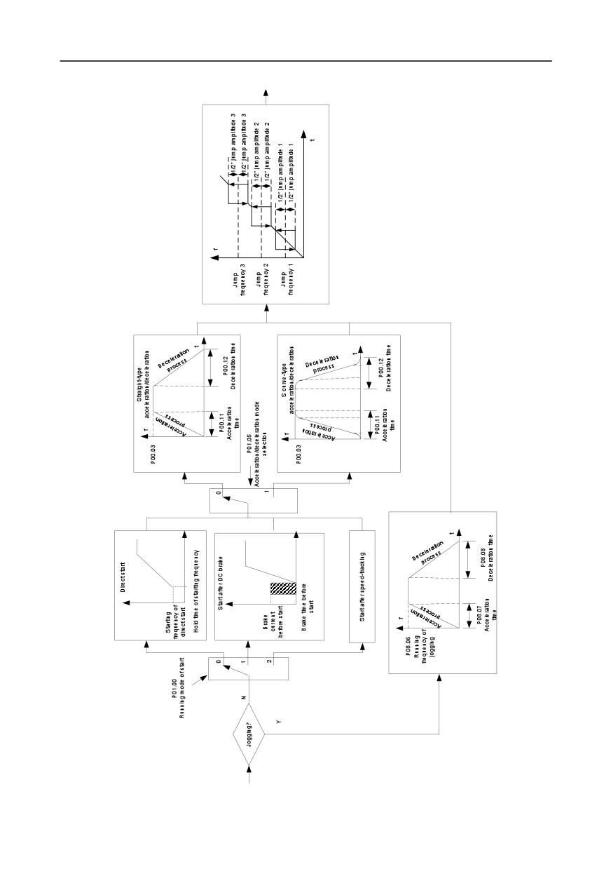
The start/stop control of the inverter is divided into three states: start after running command at
power-up; start after restart-at-power-cut function is effective; start after automatic fault reset.
Descriptions for these three start/stop control states are presented below.
There are three start modes for the inverter, which are start at starting frequency, start after DC brake,
and start after speed-tracking. Users can select the proper start mode based on field conditions.
For large-inertia load, especially in cases where reversal may occur, users can choose to start after
DC brake or start after speed-racking.
Note: It is recommended to drive synchronous motors in direct start mode.
-76-
Chapter 5
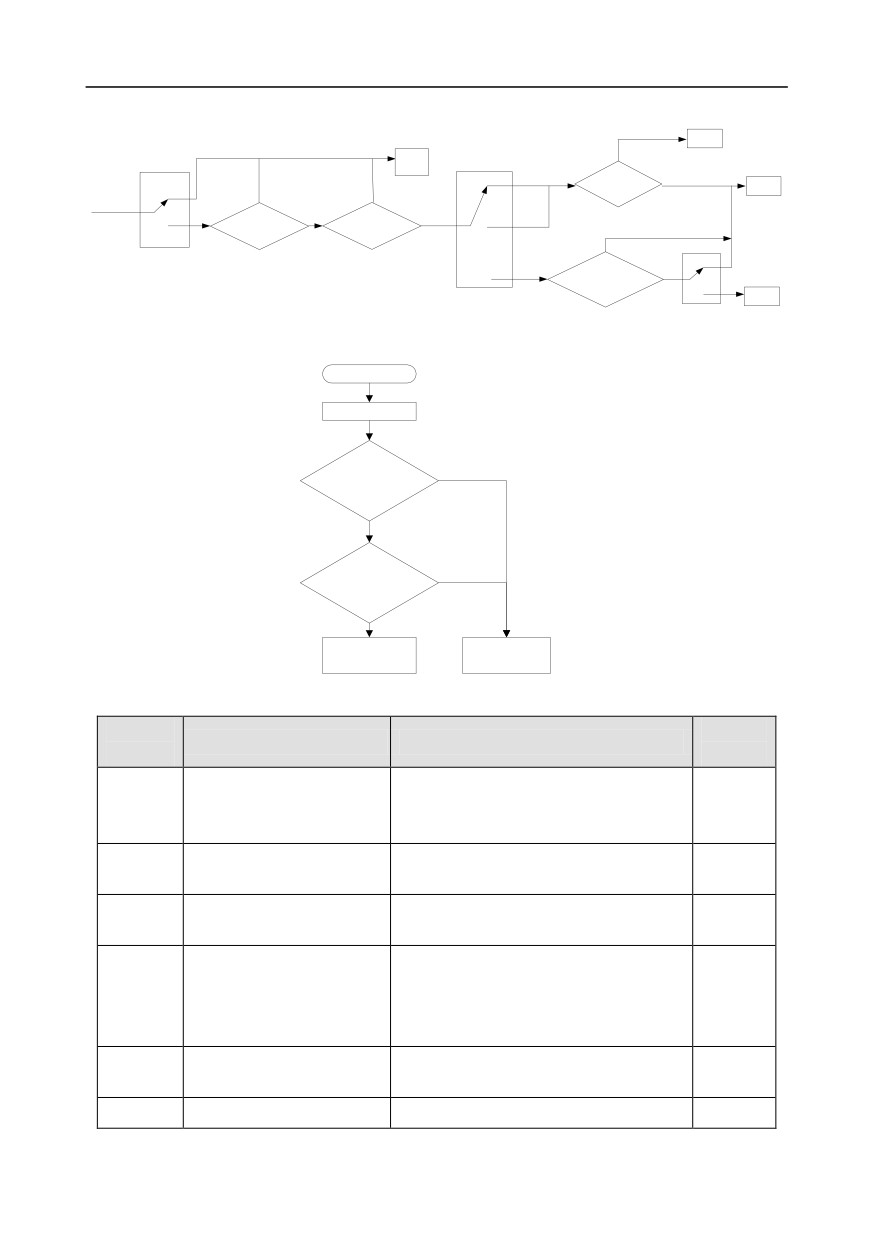
1.
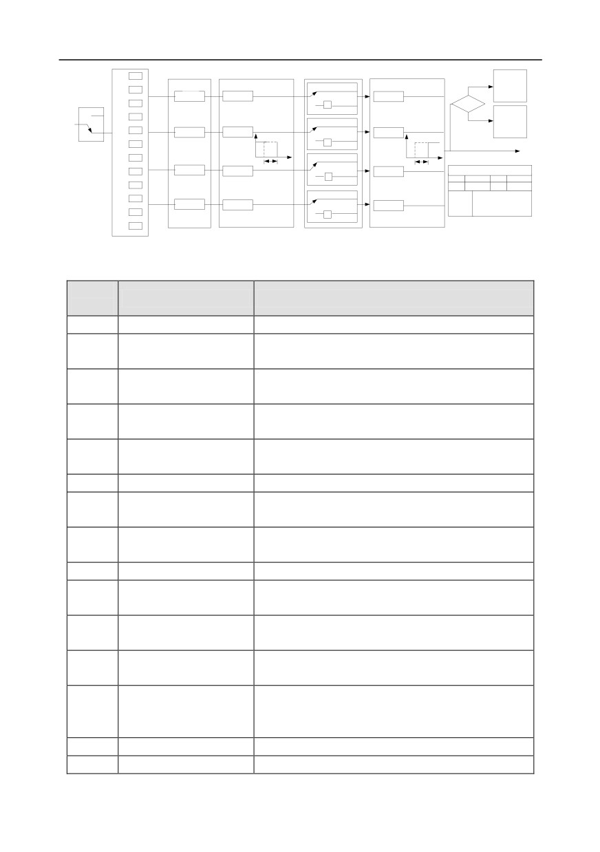
Logic diagram for running command after power-up
-77-
Chapter 5
2.
Logic diagram for restart after power-cut
Run
Standby
Run
0
Keypad
The running state
Stop
before power cut
Stop
0
N
N
Restart after
Communi
power-cut
1
Y
cation
Waiting time of restart at
Delay time of restart
Y
2
power-cut>P01.22
>P01.123
N
P01.21
(restart at power-cut)
0
Termin
FWD/REV
1
al
Whether running terminal
Y
command is valid
1
P00.01
Run
Running command channel
P01.18
(Power-on terminal running protection
selection)
3.
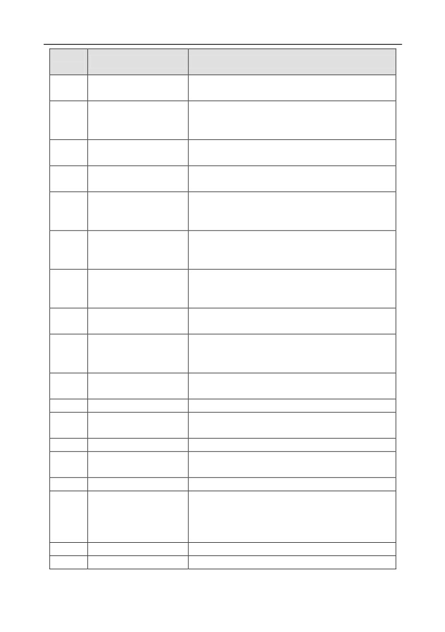
Logic diagram for restart after automatic fault reset
In running
Inverter fault
Automatic reset times
N
of inverter fault<P08.28
Y
Automatic reset
interval of inverter
N
fault>P08.29
Y
Inverter fault reset,
Display fault
start running
code, and stop
Related parameter list:
Function
Default
Name
Detailed parameter description
code
value
0: Keypad
P00.01
Running command channel
1: Terminal
0
2: Communication
Depend
P00.11
Acceleration time 1
0.0-3600.0s
on model
Depend
P00.12
Deceleration time 1
0.0-3600.0s
on model
0: Direct start
1: Start after DC brake
P01.00
Running mode of start
0
2: Start after speed-track 1
3: Start after speed-track 2
Starting frequency of direct
P01.01
0.00-50.00Hz
0.50Hz
start
P01.02
Hold time of starting
0.0-50.0s
0.0s
-78-
Chapter 5
Function
Default
Name
Detailed parameter description
code
value
frequency
P01.03
DC brake current before start
0.0-100.0%
0.0%
P01.04
DC brake time before start
0.00-50.00s
0.00s
0: Straight line
1: S curve
Acceleration/deceleration
P01.05
Note: If mode 1 is selected, it is required
0
mode
to set P01.07, P01.27 and P01.08
accordingly
0: Decelerate to stop
P01.08
Stop mode
0
1: Coast to stop
Starting frequency of DC
P01.09
0.00Hz-P00.03 (max. output frequency)
0.00Hz
brake after stop
Waiting time of DC brake
P01.10
0.00-50.00s
0.00s
after stop
P01.11
DC brake current of stop
0.0-100.0%
0.0%
P01.12
DC brake time of stop
0.00-50.00s
0.00s
Deadzone time of
P01.13
0.0-3600.0s
0.0s
forward/reverse rotation
0: switch over after zero frequency
Forward/reverse rotation
1: switch over after starting frequency
P01.14
0
switch-over mode
2: switch over after passing stop speed
and delay
P01.15
Stop speed
0.00-100.00Hz
0.50 Hz
0: Set value of speed (the only detection
P01.16
Stop speed detection mode
mode valid in SVPWM mode)
1
1: Detection value of speed
0: Terminal running command is invalid
Power-on terminal running
at power up
P01.18
0
protection selection
1: Terminal running command is valid at
power up
Action selection when the
0: Run at the lower limit frequency
running frequency is below
P01.19
1: Stop
0
lower limit (lower limit should
2: Sleep
be larger than 0)
P01.20
Wake-up-from-sleep delay
0.0-3600.0s (valid when P01.19 is 2)
0.0s
0: Restart is disabled
P01.21
Restart after power cut
0
1: Restart is enabled
-79-
Chapter 5
Function
Default
Name
Detailed parameter description
code
value
Waiting time of restart after
P01.22
0.0-3600.0s (valid when P01.21 is 1)
1.0s
power cut
P01.23
Start delay
0.0-60.0s
0.0s
P01.24
Stop speed delay
0.0-100.0s
0.0s
0: No voltage output
Open-loop 0Hz output
P01.25
1: With voltage output
0
selection
2: Output as per DC brake current of stop
Deceleration time of
P01.26
0.0-60.0s
2.0s
emergency-stop
Time of starting section of
P01.27
0.0-50.0s
0.1s
deceleration S curve
Time of ending section of
P01.28
0.0-50.0s
0.1s
deceleration S curve
P01.29
Short-circuit brake current
0.0-150.0% (rated inverter current)
0.0%
Hold time of short-circuit
P01.30
0.00-50.00s
0.00s
brake at startup
Hold time of short-circuit
P01.31
0.00-50.00s
0.00s
brake at stop
1: Forward running
2: Reverse running
4: Forward jogging
5: Reverse jogging
6: Coast to stop
P05.01-
Digital input function
7: Fault reset
/
P05.06
selection
8: Running pause
21: Acceleration/deceleration time
selection 1
22: Acceleration/deceleration time
selection 2
30: Acceleration/deceleration disabled
P08.06
Running frequency of jog
0.00Hz-P00.03 (max. output frequency)
5.00Hz
Depend
P08.07
Acceleration time at jogging
0.0-3600.0s
on model
Depend
P08.08
Deceleration time at jogging
0.0-3600.0s
on model
Depend
P08.00
Acceleration time 2
0.0-3600.0s
on model
-80-
Chapter 5
Function
Default
Name
Detailed parameter description
code
value
Depend
P08.01
Declaration time 2
0.0-3600.0s
on model
Depend
P08.02
Acceleration time 3
0.0-3600.0s
on model
Depend
P08.03
Declaration time 3
0.0-3600.0s
on model
Depend
P08.04
Acceleration time 4
0.0-3600.0s
on model
Depend
P08.05
Declaration time 4
0.0-3600.0s
on model
0.00-P00.03 (max. output frequency)
Switching frequency of
0.00Hz: No switch over
P08.19
acceleration/deceleration
If the running frequency is larger than
0
time
P08.19, switch to acceleration
/deceleration time 2
0: Max. output frequency
Reference frequency of
1: Set frequency
P08.21
acceleration/deceleration
2: 100Hz
0
time
Note: Valid for straight-line
acceleration/deceleration only
P08.28
Automatic fault reset times
0-10
0
Automatic fault reset time
P08.29
0.1-3600.0s
1.0s
interval
5.5.8 Frequency setup
GD350 series inverter supports multiple
kinds of frequency reference modes,
which can be
categorized into two types: main reference channel and auxiliary reference channel.
There are two main reference channels, namely frequency reference channel A and frequency
reference channel B. These two channels support simple arithmetical operation between each other,
and they can be switched dynamically by setting multi-function terminals.
There is one input mode for auxiliary reference channel, namely terminal UP/DOWN switch input. By
setting function codes, users can enable the corresponding reference mode and the impact made on
the inverter frequency reference by this reference mode .
The actual reference of inverter is comprised of the main reference channel and auxiliary reference
channel.
-81-
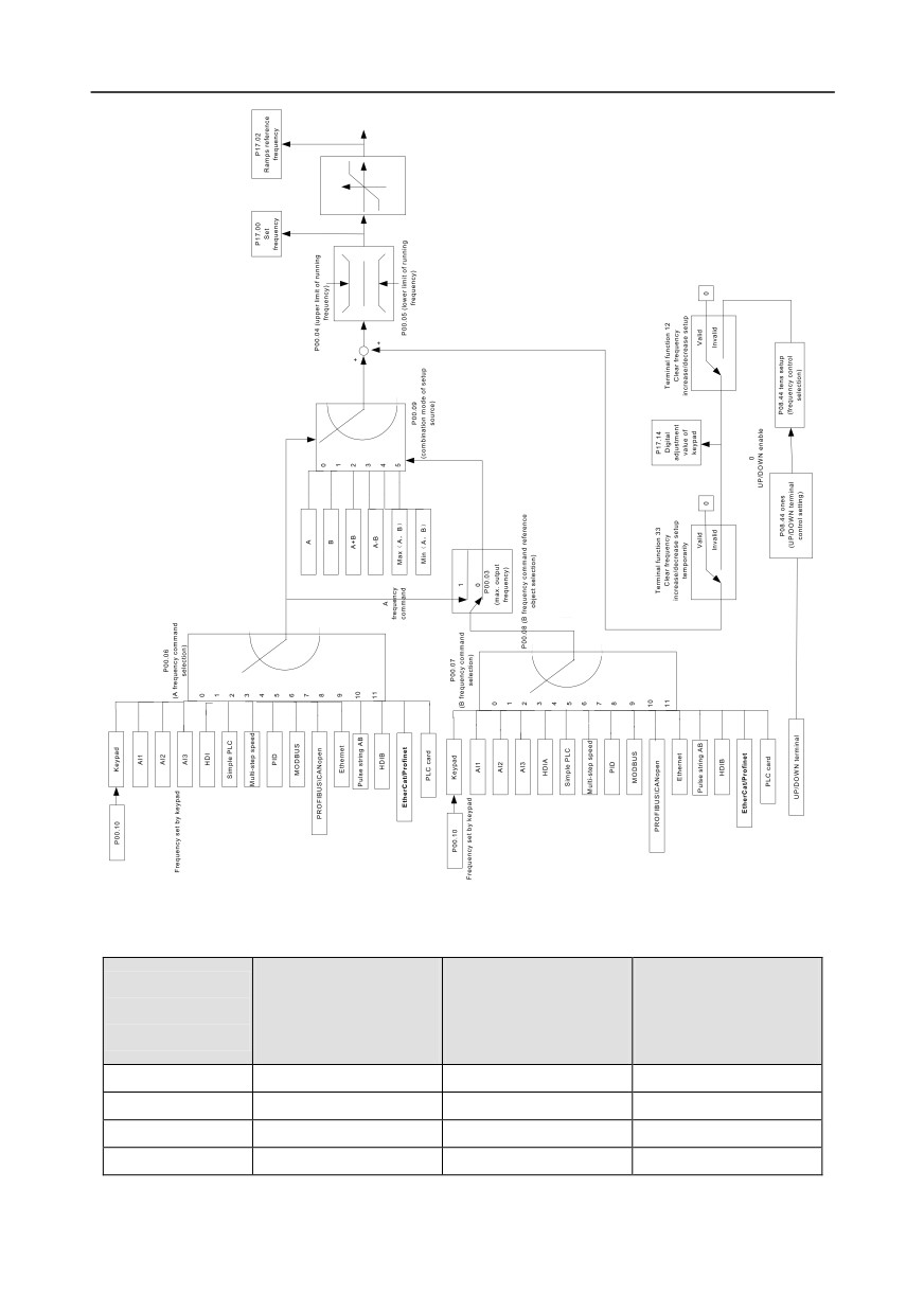
Chapter 5
GD350 inverter supports switch-over between different reference channels, and the rules for channel
switch-over are shown below.
Multi-function terminal
Multi-function terminal
Multi-function terminal
Present reference
function 13
function 14
function 15
channel
Channel A switches to
Combination setup
Combination setup
P00.09
channel B
switches to channel A
switches to channel B
A
B
/
/
B
A
/
/
A+B
/
A
B
A-B
/
A
B
-82-
Chapter 5
Multi-function terminal
Multi-function terminal
Multi-function terminal
Present reference
function 13
function 14
function 15
channel
Channel A switches to
Combination setup
Combination setup
P00.09
channel B
switches to channel A
switches to channel B
Max (A, B)
/
A
B
Min (A, B)
/
A
B
Note: "/" indicates this multi-function terminal is invalid under present reference channel.
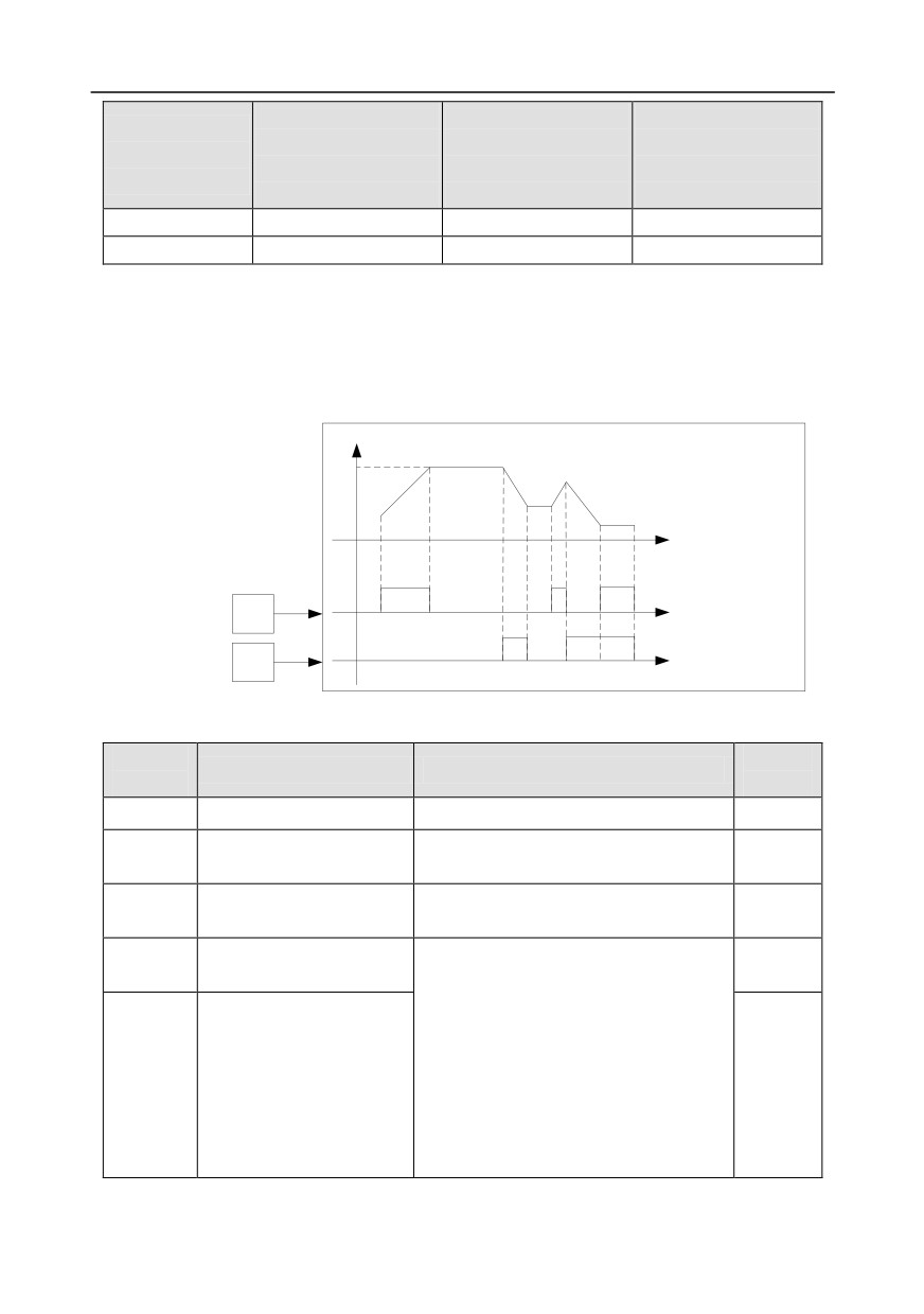
When setting the auxiliary frequency inside the inverter via multi-function terminal UP (10) and
DOWN (11), users can increase/decrease the frequency quickly by setting P08.45 (UP terminal
frequency incremental change rate) and P08.46 (DOWN terminal frequency decremental change
rate).
UP terminal frequency incremental integral speed P08.45
F
DOWN terminal frequency decremental integral speed P08.46
T
UP terminal state
UP terminal
function selection=10
Sx
T
DOWN terminal state
DOWN terminal
Sy
function selection=11
T
Related parameter list:
Function
Default
Name
Detailed parameter description
code
value
P00.03
Max. output frequency
P00.04-400.00Hz
50.00Hz
Upper limit of running
P00.04
P00.05-P00.03
50.00Hz
frequency
Lower limit of running
P00.05
0.00Hz-P00.04
0.00Hz
frequency
A frequency command
0: Set via keypad
P00.06
0
selection
1: Set via AI1
2: Set via AI2
3: Set via AI3
4: Set via high speed pulse HDIA
B frequency command
P00.07
5: Set via simple PLC program
15
selection
6: Set via multi-step speed running
7: Set via PID control
8: Set via MODBUS communication
-83-
Chapter 5
Function
Default
Name
Detailed parameter description
code
value
9: Set via PROFIBUS
/ CANopen
/
DeviceNet communication
10: Set via Ethernet communication
11: Set via high speed pulse HDIB
12: Set via pulse string AB
13: Set via EtherCat/Profinet
communication
14: Set via PLC card
15: Reserved
Reference object of B
0: Max. output frequency
P00.08
0
frequency command
1: A frequency command
0: A
1: B
Combination mode of setup
2: (A+B)
P00.09
0
source
3: (A-B)
4: Max (A, B)
5: Min (A, B)
10: Frequency increase (UP)
11: Frequency decrease (DOWN)
12: Clear frequency increase/decrease
setting
Function of multi-function
P05.01-
13: Switch-over between setup A and
digital input terminal (S1-S4,
/
P05.06
setup B
HDIA, HDIB)
14: Switch-over between combination
setup and setup A
15: Switch-over between combination
setup and setup B
P08.42
Reserved variables
/
/
P08.43
Reserved variables
/
/
0x000-0x221
Ones: Frequency enabling selection
0: UP/DOWN terminal setting is valid
1: UP/DOWN terminal setting is invalid
P08.44
UP/DOWN terminal control
Tens: Frequency control selection
0x000
0: Valid only when P00.06=0 or P00.07=0
1: Valid for all frequency modes
2: Invalid for multi-step speed when
multi-step speed takes priority
-84-
Chapter 5
Function
Default
Name
Detailed parameter description
code
value
Hundreds: Action selection at stop
0: Valid
1: Valid during running, clear after stop
2: Valid during running, clear after
receiving stop command
UP terminal frequency
P08.45
0.01-50.00 Hz/s
0.50 Hz/s
incremental change rate
DOWN terminal frequency
P08.46
0.01-50.00 Hz/s
0.50 Hz/s
decremental change rate
P17.00
Set frequency
0.00Hz-P00.03 (max. output frequency)
0.00Hz
P17.02
Ramps reference frequency
0.00Hz-P00.03 (max. output frequency)
0.00Hz
P17.14
Digital adjustment value
0.00Hz-P00.03
0.00Hz
5.5.9 Analog input
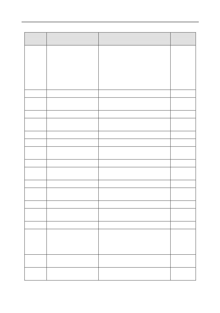
GD350 series inverter carries two analog input terminals (AI1 is 0-10V/0-20mA (voltage input or
current input can be set by P05.50); AI2 is -10-10V) and two high-speed pulse input terminals. Each
input can be filtered separately, and the corresponding reference curve can be set by adjusting the
reference corresponds to the max. value and min. value.
Analog input curve setting
Analog input filter
P05.24
P05.25
P05.28
AI1 input voltage
P05.26
P05.27
P17.19
AI1
P05.29
AI2 input voltage
P05.30
P05.31
P17.20
P05.32
P05.37
P05.33
P05.34
AI2
P05.35
P05.36
HDIA input frequency
P17.21
0
0
P05.39
HDIA
1
P05.40
P05.43
1
P05.41
2
P05.42
P05.00
P05.38
(HDIA input type)
(HDIA high-speed pulse input function
selection)
HDIB input frequency
0
0
AI1/AI2/HDI
P17.22
HDIB
1
P05.45
P05.49
1
P05.46
2
P05.47
P05.48
P05.00
(HDIB input type)
P05.44
(HDIB high-speed pulse input function
selection)
Ones:
0: Set input via frequency
P05.00
0: HDIA is high-speed pulse input
P05.38
1: Reserved
1: HDIA is digital input
2: Input via encoder
Tens:
0: Set input via frequency
P05.00
0: HDIB is high-speed pulse input
P05.44
1: Reserved
1: HDIB is digital input
2: Input via encoder
-85-
Chapter 5
Related parameter list:
Function
Default
Name
Detailed parameter description
code
value
0x00-0x11
Ones: HDIA input type
0: HDIA is high-speed pulse input
P05.00
HDI input type
1: HDIA is digital input
0x00
Tens: HDIB input type
0: HDIB is high-speed pulse input
1: HDIB is digital input
P05.24
Lower limit value of AI1
0.00V-P05.26
0.00V
Corresponding setting of
P05.25
-100.0%-100.0%
0.0%
lower limit of AI1
P05.26
Upper limit value of AI1
P05.24-10.00V
10.00V
Corresponding setting of
P05.27
-100.0%-100.0%
100.0%
upper limit of AI1
P05.28
Input filter time of AI1
0.000s-10.000s
0.100s
P05.29
Lower limit value of AI2
-10.00V-P05.31
-10.00V
Corresponding setting of
P05.30
-100.0%-100.0%
-100.0%
lower limit of AI2
P05.31
Intermediate value 1 of AI2
P05.29-P05.33
0.00V
Corresponding setting of
P05.32
-100.0%-100.0%
0.0%
intermediate value 1 of AI2
P05.33
Intermediate value 2 of AI2
P05.31-P05.35
0.00V
Corresponding setting of
P05.34
-100.0%-100.0%
0.0%
intermediate value 2 of AI2
P05.35
Upper limit value of AI2
P05.33-10.00V
10.00V
Corresponding setting of
P05.36
-100.0%-100.0%
100.0%
upper limit of AI2
P05.37
Input filter time of AI2
0.000s-10.000s
0.100s
0: Set input via frequency
HDIA high-speed pulse input
1: Reserved
P05.38
0
function
2: Input via encoder, used in
combination with HDIB
Lower limit frequency of
P05.39
0.000 KHz - P05.41
0.000KHz
HDIA
Corresponding setting of
P05.40
-100.0%-100.0%
0.0%
lower limit frequency of HDIA
-86-
Chapter 5
Function
Default
Name
Detailed parameter description
code
value
Upper limit frequency of
P05.41
P05.39 -50.000KHz
50.000KHz
HDIA
Corresponding setting of
P05.42
upper limit frequency of
-100.0%-100.0%
100.0%
HDIA
HDIA frequency input filter
P05.43
0.000s-10.000s
0.030s
time
0: Set input via frequency
HDIB high-speed pulse input
1: Reserved
P05.44
0
function selection
2: Input via encoder, used in
combination with HDIA
Lower limit frequency of
P05.45
0.000 KHz - P05.47
0.000KHz
HDIB
Corresponding setting of
P05.46
-100.0%-100.0%
0.0%
lower limit frequency of HDIB
Upper limit frequency of
P05.47
P05.45 -50.000KHz
50.000KHz
HDIB
Corresponding setting of
P05.48
upper limit frequency of
-100.0%-100.0%
100.0%
HDIB
HDIB frequency input filter
P05.49
0.000s-10.000s
0.030s
time
0-1
P05.50
AI1 input signal type
0: Voltage type
0
1: Current type
5.5.10 Analog output
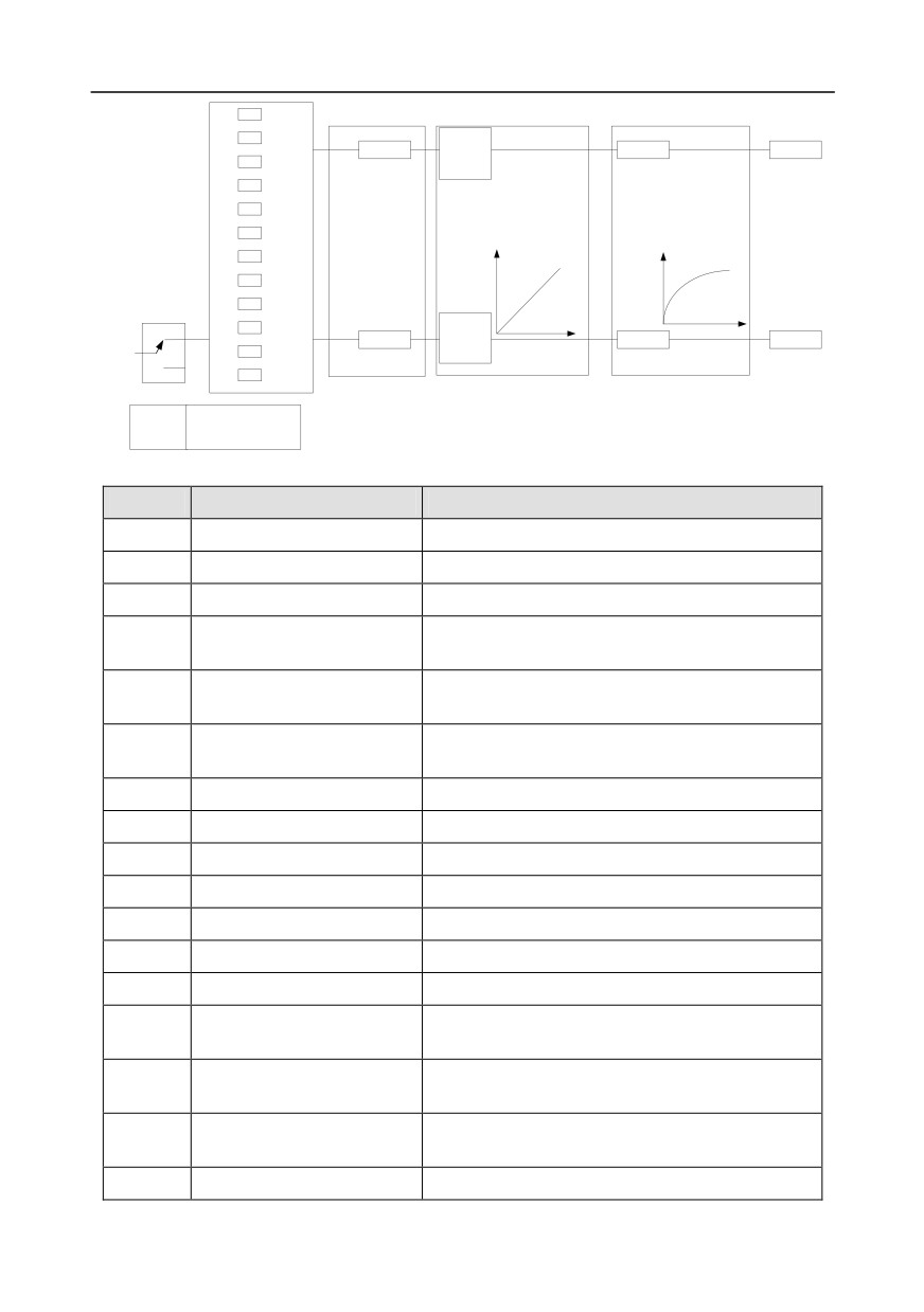
GD350 series inverter carries one analog output terminal (0-10V/0-20mA) and one high-speed pulse
output terminal. Analog output signals can be filtered separately, and the proportional relation can be
adjusted by setting the max. value, min. value, and the percentage of their corresponding output.
Analog output signal can output motor speed, output frequency, output current, motor torque and
motor power at a certain proportion.
-87-
Chapter 5
0
Analog output selection
Analog output curve setting
Analog output filter
1
P06.17
P06.14
P06.18
P06.21
AO1
2
P06.19
(Default value is 0)
P06.20
3
P06.00
(HDO output type)
P06.27
0
P06.28
P06.16
P06.29
P06.31
HDO
19
P06.30
1
(Default value is 0)
20
0: Open collector high-speed
P06.00
pulse output
1: Open-collector output
Instructions for output:
Set value
Function
Description
0
Running frequency
0-Max. output frequency
1
Set frequency
0-Max. output frequency
2
Ramps reference frequency
0-Max. output frequency
0-Synchronous speed corresponding to Max. output
3
Running speed
frequency
Output current (relative to
4
0-Two times of rated current of inverter
inverter)
Output current (relative to
5
0-Two times of rated current of motor
motor)
6
Output voltage
0-1.5 times of rated voltage of inverter
7
Output power
0-Two times of rated power
8
Set torque value
0-Two times of rated current of motor
9
Output torque
0-Two times of rated current of motor
10
AI1 input value
0-10V/0-20mA
11
AI2 input value
-10V-10V
12
AI3 input value
0-10V/0-20mA
Input value of high-speed
13
0.00-50.00kHz
pulse HDIA
Set value 1 of MODBUS
14
-1000-1000, 1000 corresponds to 100.0%
communication
Set value 2 of MODBUS
-1000-1000, 1000 corresponds to 100.0%
15
communication
16
Set value 1 of
-1000-1000, 1000 corresponds to 100.0%
-88-
Chapter 5
Set value
Function
Description
PROFIBUS\CANopen
communication
Set value 2 of
17
PROFIBUS\CANopen
-1000-1000, 1000 corresponds to 100.0%
communication
Set value 1 of Ethernet
-1000-1000, 1000 corresponds to 100.0%
18
communication
Set value 2 of Ethernet
-1000-1000, 1000 corresponds to 100.0%
19
communication
Input value of high-speed
20
0.00-50.00kHz
pulse HDIB
21
Reserved variable
Torque current (bipolar, 100%
0-Two times of rated current of motor
22
corresponds to 10V)
Exciting current (100%
0-One times of rated current of motor
23
corresponds to 10V)
24
Set frequency (bipolar)
0-Max. output frequency
Ramps reference frequency
0-Max. output frequency
25
(bipolar)
26
Running speed (bipolar)
0-Max. output frequency
Set value 2 of
-1000-1000,
1000 corresponds
to
27
EtherCat/Profinet
100.0%
communication
28
C_AO1 from CODESYS
1000 corresponds to 100.0%
29
C_AO2 from CODESYS
1000 corresponds to 100.0%
30
Running speed
0-Two times of rated synchronous speed of motor
31-47
Reserved variable
Related parameter list:
Function
Default
Name
Detailed parameter description
code
value
0: Open collector high-speed pulse
P06.00
HDO output type
output
0
1: Open collector output
P06.14
AO1 output selection
0: Running frequency
0
1: Set frequency
P06.15
Reserved variable
0
2: Ramps reference frequency
P06.16
HDO high-speed pulse output
0
3: Running speed
-89-
Chapter 5
Function
Default
Name
Detailed parameter description
code
value
4: Output current (relative to inverter)
5: Output current (relative to motor)
6: Output voltage
7: Output power
8: Set torque value
9: Output torque
10: Analog AI1 input value
11: Analog AI2input value
12: Analog AI3 input value
13: Input value of high-speed pulse
HDIA
14: Set value 1 of MODBUS
communication
15: Set value 2 of MODBUS
communication
16: Set value 1 of PROFIBUS\CANopen
communication
17: Set value 2 of PROFIBUS\CANopen
communication
18: Set value 1 of Ethernet
communication
19: Set value 2 of Ethernet
communication
20: Input value of high-speed pulse
HDIB
21: Set value 1 of EtherCat/Profinet
communication
22: Torque current (bipolar, 100%
corresponds to 10V)
23: Exciting current (100% corresponds
to 10V)
24: Set frequency (bipolar)
25: Ramps reference frequency
(bipolar)
26: Running speed (bipolar)
27: Set value 2 of EtherCat/Profinet
communication
28: C_AO1 from CODESYS (set P27.00
to 1)
-90-
Chapter 5
Function
Default
Name
Detailed parameter description
code
value
29: C_AO2 from CODESYS (set P27.00
to 1)
30: Running speed
31-47: Reserved variable
P06.17
Lower limit of AO1 output
-100.0%-P06.19
0.0%
Corresponding AO1 output of
P06.18
0.00V-10.00V
0.00V
lower limit
P06.19
Upper limit of AO1 output
P06.17-100.0%
100.0%
Corresponding AO1 output of
P06.20
0.00V-10.00V
10.00V
upper limit
P06.21
AO1 output filter time
0.000s-10.000s
0.000s
P06.22-
Reserved variable
0-65535
0
P06.26
P06.27
Lower limit of HDO output
-100.0%-P06.29
0.0%
Corresponding HDO output of
P06.28
0.00-50.00kHz
0.0kHz
lower limit
P06.29
Upper limit of HDO output
P06.27-100.0%
100.0%
Corresponding HDO output of
P06.30
0.00-50.00kHz
50.00kHz
upper limit
P06.31
HDO output filter time
0.000s-10.000s
0.000s
5.5.11 Digital input
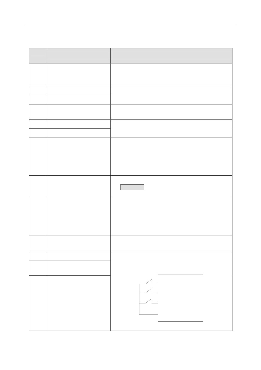
GD350 series inverter carries four programmable digital input terminals and two HDI input terminals.
The function of all the digital input terminals can be programmed by function codes. HDI input
terminal can be set to act as high-speed pulse input terminal or common digital input terminal; if it is
set to act as high-speed pulse input terminal, users can also set HDIA or HDIB high-speed pulse input
to serve as the frequency reference and encoder signal input.
P05.08 (input terminal polarity)
P05.09 (digital filter time)
Digital function selection
0
P05.12
P05.13
0
S1
1
-1
T delay
T delay
P05.01
(Default value is 1)
1
0
P05.14
P05.15
S2
1
T delay
T delay
P05.02
2
-1
(Default value is 4)
0
P05.16
P05.17
3
Run
P17.11
S3
T delay
T delay
P05.03
Digital input
1
-1
terminal state
(Default value is 7)
4
0
P05.18
P05.19
S4
T delay
T delay
P05.04
Fault?
1
-1
5
(Default value is 0)
Fault
P07.39
Input terminal
state of present
P05.00
fault
(HDI input type)
0
P05.20
P05.21
HDIA
T delay
T delay
P05.05
0
1
-1
(Default value is 0)
1
0
P05.22
P05.23
HD1B
1
T delay
T delay
P05.06
-1
(Default value is 0)
29
30
-91-
Chapter 5
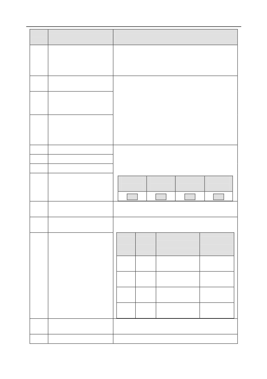
This parameter is used to set the corresponding function of digital multi-function input terminals.
Note: Two different multi-function input terminals cannot be set to the same function.
Set
Function
Description
value
The inverter does not act even if there is signal input;
0
No function
users can set the unused terminals to "no function" to
avoid misacts.
1
Forward running (FWD)
Control the forward/reverse running of the inverter by
2
Reverse running (REV)
external terminals.
Set the inverter running mode to 3-Wire control mode by
3
3-Wire control/Sin
this terminal. See P05.13 for details.
4
Forward jogging
Frequency when jogging, see P08.06, P08.07 and
5
Reverse jogging
P08.08 for jogging acceleration/deceleration time.
The inverter blocks output, and the stop process of motor
is uncontrolled by the inverter. This mode is applied in
6
Coast to stop
cases of large-inertia load and free stop time; its
definition is the same with P01.08, and it is mainly used in
remote control.
External fault reset function, its function is the same with
7
Fault reset
the STOP/RST key on the keypad. This function can be
used in remote fault reset.
The inverter decelerates to stop, however, all the running
parameters are in memory state, eg PLC parameter,
8
Running pause
wobbling frequency, and PID parameter. After this signal
disappears, the inverter will revert to the state before
stop.
When external fault signal is transmitted to the inverter,
9
External fault input
the inverter releases fault alarm and stops.
10
Frequency increase (UP)
Used to change the frequency-increase/decrease
Frequency decrease
command when the frequency is given by external
11
(DOWN)
terminals.
K1
UP terminal
K2
DOWN terminal
Clear frequency
K3
UP/DOWM
12
increase/decrease setting
Zeroing terminal
COM
The terminal used to clear frequency-increase/decrease
-92-
Chapter 5
Set
Function
Description
value
setting can clear the frequency value of auxiliary channel
set by UP/DOWN, thus restoring the reference frequency
to the frequency given by main reference frequency
command channel.
Switching between A setting
This function is used to switch between the frequency
13
and B setting
setting channels.
Switching between
A frequency reference channel and B frequency
14
combination setting and A
reference channel can be switched by no. 13 function;
setting
the combination channel set by P00.09 and the A
frequency reference channel can be switched by no. 14
Switching between
function; the combination channel set by P00.09 and the
15
combination setting and B
B frequency reference channel can be switched by no. 15
setting
function.
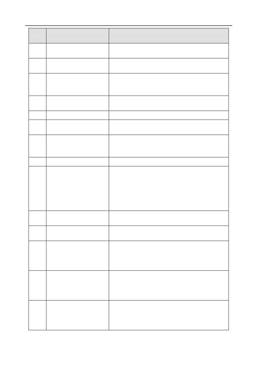
16
Multi-step speed terminal 1
16-step speeds can be set by combining digital states of
these four terminals.
17
Multi-step speed terminal 2
Note: Multi-step speed 1 is low bit, multi-step speed 4
18
Multi-step speed terminal 3
is high bit.
Multi-step
Multi-step
Multi-step
Multi-step
19
Multi-step speed terminal 4
speed 4
speed 3
speed 2
speed 1
BIT3
BIT2
BIT1
BIT0
Pause multi-step speed selection function to keep the set
20
Multi-step speed pause
value in present state.
Acceleration/deceleration
Use these two terminals to select four groups of
21
time selection 1
acceleration/decoration time.
Acceleration or
Terminal
Terminal
Corresponding
deceleration time
1
2
parameter
selection
Acceleration/
OFF
OFF
P00.11/P00.12
deceleration time 1
Acceleration/deceleration
22
Acceleration/
time selection 2
ON
OFF
P08.00/P08.01
deceleration time 2
Acceleration/
OFF
ON
P08.02/P08.03
deceleration time 3
Acceleration/
ON
ON
P08.04/P08.05
deceleration time 4
Restart simple PLC process and clear previous PLC
23
Simple PLC stop reset
state information.
24
Simple PLC pause
The program pauses during PLC execution, and keeps
-93-
Chapter 5
Set
Function
Description
value
running in current speed step. After this function is
cancelled, simple PLC keeps running.
PID is ineffective temporarily, and the inverter maintains
25
PID control pause
current frequency output.
The inverter pauses at current output. After this function
Wobbling frequency pause
26
is canceled, it continues wobbling-frequency operation at
(stop at current frequency)
current frequency.
Wobbling frequency reset
27
The set frequency of inverter reverts to center frequency.
(revert to center frequency)
28
Counter reset
Zero out the counter state.
Switching between speed
The inverter switches from torque control mode to speed
29
control and torque control
control mode, or vice versa.
Ensure the inverter will not be impacted by external
Acceleration/deceleration
30
signals (except for stop command), and maintains current
disabled
output frequency.
31
Counter trigger
Enable pulse counting of the counter.
When the terminal is closed, the frequency value set by
UP/DOWN can be cleared to restore the reference
Clear frequency
frequency to the frequency given by frequency command
33
increase/decrease setting
channel; when terminal is disconnected, it will revert to
temporarily
the frequency value after frequency increase/decrease
setting.
The inverter starts DC brake immediately after the
34
DC brake
command becomes valid.
Switching between motor 1
When this terminal is valid, users can realize switch-over
35
and motor 2
control of two motors.
When this terminal is valid, the running command
Command switches to
channel will switch to keypad compulsorily. If this function
36
keypad
becomes invalid, the running command channel will
revert to the original state.
When this terminal is valid, the running command
Command switches to
channel will switch to terminal compulsorily. If this
37
terminal
function becomes invalid, the running command channel
will revert to the original state.
When this terminal is valid, the running command
Command switches to
channel will switch to communication compulsorily. If this
38
communication
function becomes invalid, the running command channel
will revert to the original state.
-94-
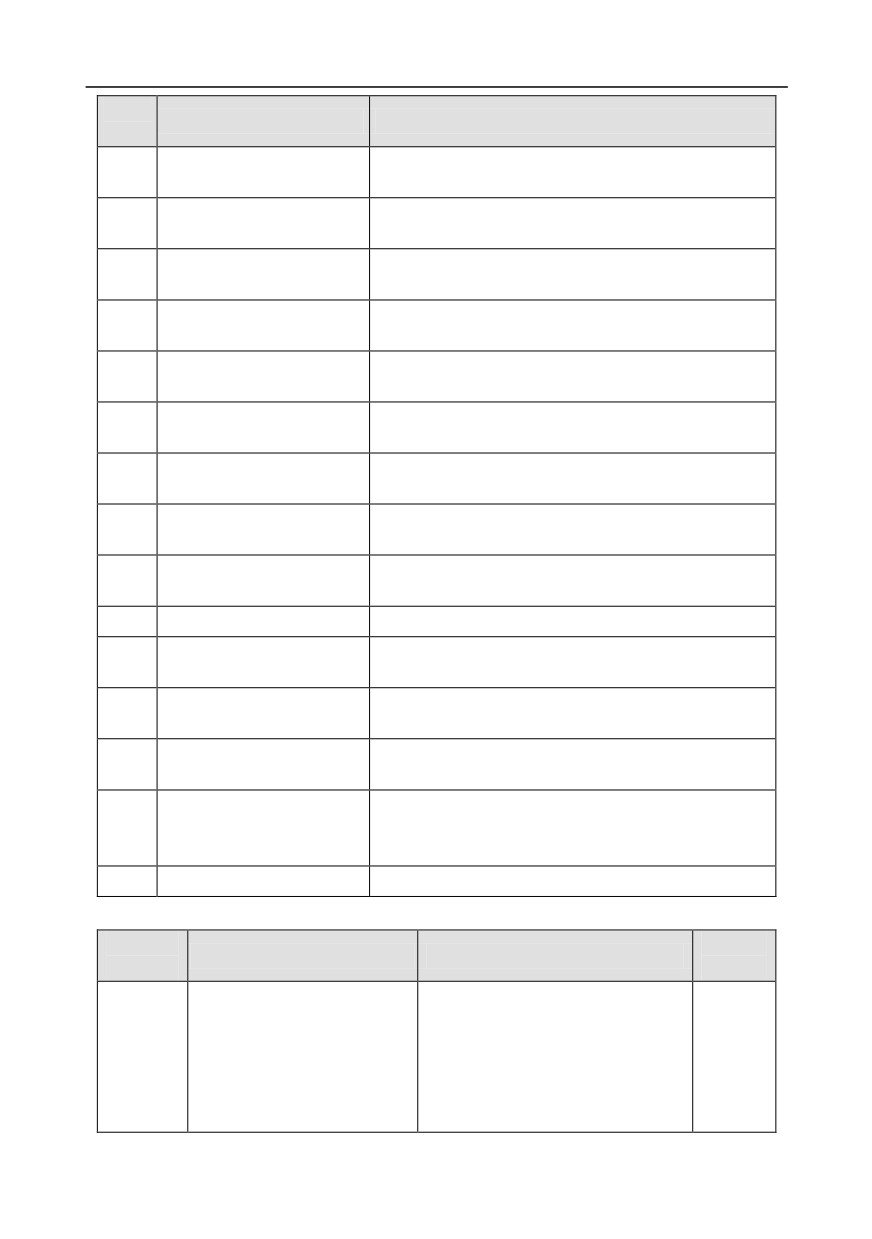
Chapter 5
Set
Function
Description
value
When this terminal is valid, motor pre-exciting will be
39
Pre-exciting command
started until this terminal becomes invalid.
Zero out power consumption
After this command becomes valid, the power
40
quantity
consumption quantity of the inverter will be zeroed out.
Maintain power consumption
When this command is valid, current operation of the
41
quantity
inverter will not impact the power consumption quantity.
Source of upper torque limit
When this command is valid, the upper limit of the torque
42
switches to keypad
will be set by keypad
When this command is valid, the motor decelerate to
56
Emergency stop
emergency stop as per the time set by P01.26.
Motor over-temperature fault
57
Motor stops at motor over-temperature fault input.
input
When this terminal is valid in stop state, switch to
59
FVC switches to V/F control
SVPWM control.
When this terminal is valid in stop state, switch to
60
Switch to FVC control
closed-loop vector control.
Switching the output polarity of PID, this terminal should
61
PID polarity switch-over
be used in conjunction with P09.03
66
Zero out the counter
Zero out the position counting value
When the terminal function is valid, the pulse input is
67
Pulse increase
increased according to the P21.27 pulse speed.
Enable pulse
When the pulse superimposition is enabled, pulse
68
superimposition
increase and pulse decrease are effective.
When the terminal function is valid, the pulse input is
69
Pulse decrease
decreased according to the P21.27 pulse speed.
When the terminal is valid, the proportional numerator is
70
Electronic gear selection
switched to the P21.30 numerator of the 2nd command
ratio.
71-79
Reserved variables
/
Related parameter list:
Function
Default
Name
Detailed parameter description
code
value
0x00-0x11
Ones: HDIA input type
0: HDIA is high-speed pulse input
P05.00
HDI input type
0x00
1: HDIA is digital input
Tens: HDIB input type
0: HDIB is high-speed pulse input
-95-
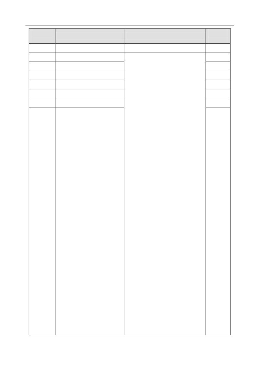
Chapter 5
Function
Default
Name
Detailed parameter description
code
value
1: HDIB is digital input
P05.01
Function of S1 terminal
0: No function
1
1: Forward running
P05.02
Function of S2 terminal
4
2: Reverse running
P05.03
Function of S3 terminal
7
3: 3-Wire control/Sin
P05.04
Function of S4 terminal
0
4: Forward jogging
P05.05
Function of HDIA terminal
5: Reverse jogging
0
6: Coast to stop
P05.06
Function of HDIB terminal
0
7: Fault reset
8: Running pause
9: External fault input
10: Frequency increase (UP)
11: Frequency decrease (DOWN)
12: Clear frequency
increase/decrease setting
13: Switch-over between setup A and
setup B
14: Switch-over between
combination setting and A setting
15: Switch-over between
combination setting and setup B
16: Multi-step speed terminal 1
17: Multi-step speed terminal 2
P05.07
Reserved variables
18: Multi-step speed terminal 3
0
19: Multi-step speed terminal 4
20: Multi-step speed pause
21: Acceleration/deceleration time
selection 1
22: Acceleration/deceleration time
selection 2
23: Simple PLC stop reset
24: Simple PLC pause
25: PID control pause
26: Wobbling frequency pause
27: Wobbling frequency reset
28: Counter reset
29: Switching between speed control
and torque control
30: Acceleration/deceleration
-96-
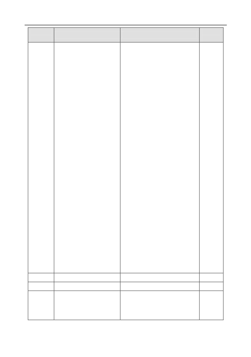
Chapter 5
Function
Default
Name
Detailed parameter description
code
value
disabled
31: Counter trigger
32: Reserved
33: Clear frequency
increase/decrease setting
temporarily
34: DC brake
35: Switching between motor 1 and
motor 2
36: Command switches to keypad
37: Command switches to terminal
38: Command switches to
communication
39: Pre-exciting command
40: Zero out power consumption
quantity
41: Maintain power consumption
quantity
42: Source of upper torque limit
switches to keypad
56: Emergency stop
57: Motor over-temperature fault
input
59: Switch to V/F control
60: Switch to FVC control
61: PID polarity switch-over
66: Zero out encoder counting
67: Pulse increase
68: Enable pulse superimposition
69: Pulse decrease
70: Electronic gear selection
71-79: Reserved
P05.08
Polarity of input terminal
0x00-0x3F
0x00
P05.09
Digital filter time
0.000-1.000s
0.010s
0x00-0x3F (0: disable, 1: enable)
BIT0: S1 virtual terminal
P05.10
Virtual terminal setting
0x00
BIT1: S2 virtual terminal
BIT2: S3 virtual terminal
-97-
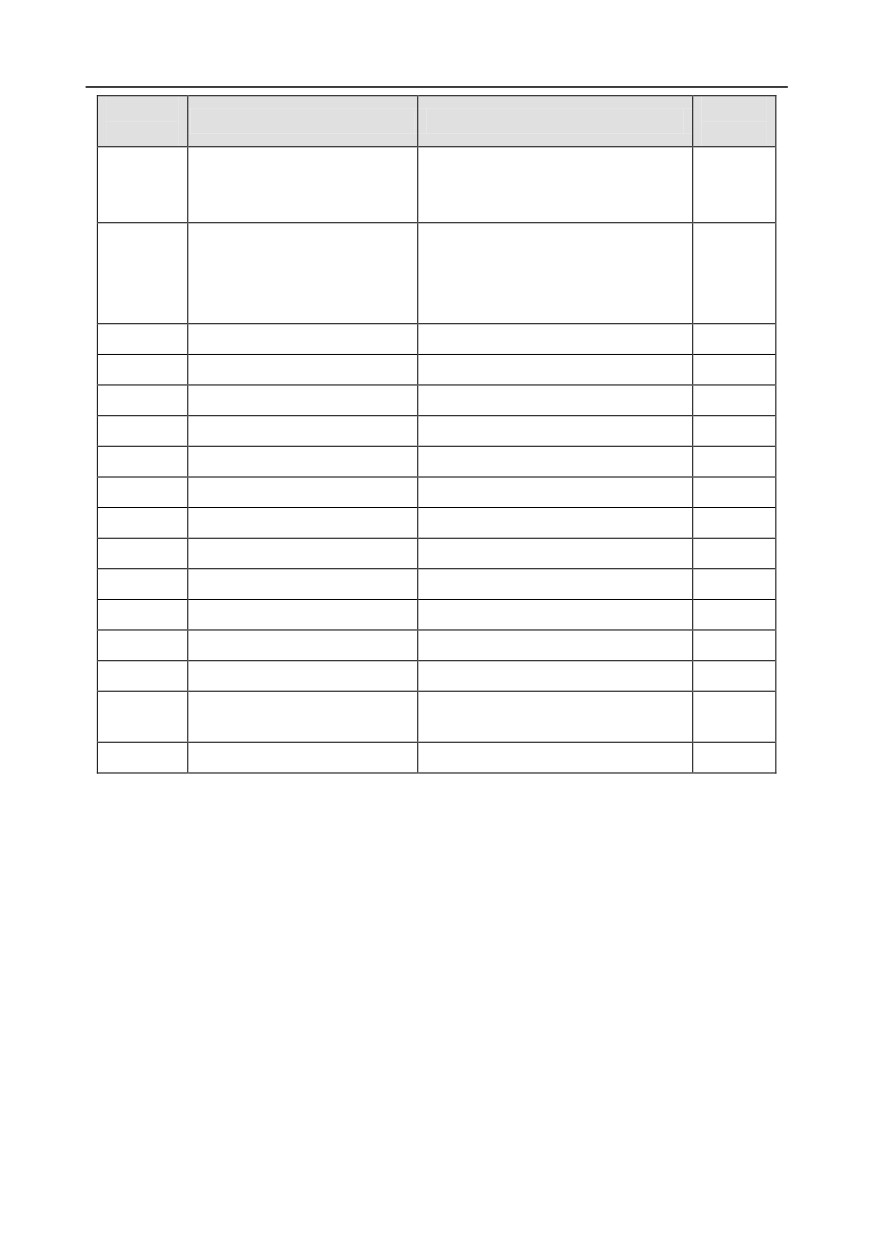
Chapter 5
Function
Default
Name
Detailed parameter description
code
value
BIT3: S4 virtual terminal
BIT4: HDIA virtual terminal
BIT8: HDIB virtual terminal
0: 2-Wire control 1
1: 2-Wire control 2
P05.11
2/3 Wire control mode
0
2: 3-Wire control 1
3: 3-Wire control 2
P05.12
S1 terminal switch-on delay
0.000-50.000s
0.000s
P05.13
S1 terminal switch-off delay
0.000-50.000s
0.000s
P05.14
S2 terminal switch-on delay
0.000-50.000s
0.000s
P05.15
S2 terminal switch-off delay
0.000-50.000s
0.000s
P05.16
S3 terminal switch-on delay
0.000-50.000s
0.000s
P05.17
S3 terminal switch-off delay
0.000-50.000s
0.000s
P05.18
S4 terminal switch-on delay
0.000-50.000s
0.000s
P05.19
S4 terminal switch-off delay
0.000-50.000s
0.000s
P05.20
HDIA terminal switch-on delay
0.000-50.000s
0.000s
P05.21
HDIA terminal switch-off delay
0.000-50.000s
0.000s
P05.22
HDIB terminal switch-on delay
0.000-50.000s
0.000s
P05.23
HDIB terminal switch-off delay
0.000-50.000s
0.000s
Input terminal state of present
P07.39
/
0
fault
P17.12
Digital input terminal state
/
0
5.5.12 Digital output
GD350 series inverter carries two groups of relay output terminals, one open collector Y output
terminal and one high-speed pulse output (HDO) terminal. The function of all the digital output
terminals can be programmed by function codes, of which the high-speed pulse output terminal HDO
can also be set to high-speed pulse output or digital output by function code.
-98-
Chapter 5
Digital output selection
Digital switch-on delay
P06.05 output polarity
0
selection
Digital switch-off delay
P17.12
P06.06
Run
Digital input
1
Y
0
P06.07
terminal state
P06.01
T delay
T delay
2
1
-1
Fault?
(Default value: 0)
0
P07.40
3
Fault
Digital output
HDO
P06.08
0
P06.09
terminal state
1
4
P06.02
T delay
T delay
of current fault
1
5
(Default value: 0)
-1
P06.00
HDO
input type
ROI
P06.10
0
delay
P06.11
delay
P06.03
T delay
T delay
P06.05, P17.12, P07.40 display
(Default value: 1)
1
-1
Y
BIT0
HDO
BIT1
ROI
BIT2
RO2
BIT3
RO2
P06.12
0
P06.13
0: Open collector high-
P06.04
T delay
T delay
P06.00
speed pulse output
1
1: Open collector output
29
(Default value: 5)
-1
30
The table below lists the options for the above four function parameters, and users are allowed to
select the same output terminal functions repetitively.
Set
Function
Description
value
0
Invalid
Output terminal has no function
Output ON signal when there is frequency output during
1
In running
running
Output ON signal when there is frequency output during
2
In forward running
forward running
Output ON signal when there is frequency output during
3
In reverse running
reverse running
Output ON signal when there is frequency output during
4
In jogging
jogging
5
Inverter fault
Output ON signal when inverter fault occurred
Frequency level detection
6
Refer to P08.32 and P08.33
FDT1
Frequency level detection
7
Refer to P08.34 and P08.35
FDT2
8
Frequency reached
Refer to P08.36
Output ON signal when the inverter output frequency and
9
Running in zero speed
reference frequency are both zero.
Reach upper limit
Output ON signal when the running frequency reaches
10
frequency
upper limit frequency
Reach lower limit
Output ON signal when the running frequency reached
11
frequency
lower limit frequency
Main circuit and control circuit powers are established,
12
Ready to run
the protection functions do not act; when the inverter is
ready to run, output ON signal.
13
In pre-exciting
Output ON signal during pre-exciting of the inverter
14
Overload pre-alarm
Output ON signal after the pre-alarm time elapsed based
-99-
Chapter 5
Set
Function
Description
value
on the pre-alarm threshold; see P11.08-P11.10 for
details.
Output ON signal after the pre-alarm time elapsed based
15
Underload pre-alarm
on the pre-alarm threshold; see P11.11-P11.12 for
details.
Simple PLC state
Output signal when current stage of simple PLC is
16
completed
completed
Simple PLC cycle
Output signal when a single cycle of simple PLC
17
completed
operation is completed
Output corresponding signal based on the set value of
Virtual terminal output of
23
MODBUS; output ON signal when it is set to 1, output
MODBUS communication
OFF signal when it is set to 0
Virtual terminal output of
Output corresponding signal based on the set value of
24
POROFIBUS\CANopen
PROFIBUS\CANopen; output ON signal when it is set to
communication
1, output OFF signal when it is set to 0
Output corresponding signal based on the set value of
Virtual terminal output of
25
Ethernet; output ON signal when it is set to 1, output OFF
Ethernet communication
signal when it is set to 0.
DC bus voltage
Output is valid when the bus voltage is above the
26
established
undervoltage threshold of the inverter
27
Z pulse output
Output is valid when the encoder Z pulse is arrived, and
is invalid after 10 ms.
28
During pulse superposition
Output is valid when the pulse superposition terminal
input function is valid
29
STO action
Output when STO fault occurred
30
Positioning completed
Output is valid when position control positioning is
completed
31
Spindle zeroing completed
Output is valid when spindle zeroing is completed
32
Spindle scale-division
Output is valid when spindle scale-division is completed
completed
33
In speed limit
Output is valid when the frequency is limited
34
Virtual terminal output of
The corresponding signal is output according to the set
EtherCat/Profinet
value of Profinet communication. When it is set to 1, the
communication
ON signal is output, and when it is set to 0, the OFF
signal is output.
35
Reserved
36
Speed/position control
Output is valid when the mode switch-over is completed
-100-
Chapter 5
Set
Function
Description
value
switch-over completed
37-40
Reserved
41
C_Y1
C_Y1 from CODESYS (set P27.00 to 1)
42
C_Y2
C_Y2 from CODESYS (set P27.00 to 1)
43
C_HDO
C_HDO from CODESYS (set P27.00 to 1)
44
C_RO1
C_RO1 from CODESYS (set P27.00 to 1)
45
C_RO2
C_RO2 from CODESYS (set P27.00 to 1)
46
C_RO3
C_RO3 from CODESYS3 (set P27.00 to 1)
47
C_RO4
C_RO4 from CODESYS (set P27.00 to 1)
48-63
Reserved variables
/
Related parameter list:
Function
Default
Name
Detailed parameter description
code
value
0: Open collector high-speed pulse output
P06.00
HDO output type
0
1: Open collector output
P06.01
Y output selection
0: Invalid
0
1: In running
P06.02
HDO output selection
0
2: In forward running
Relay RO1 output
P06.03
3: In reverse running
1
selection
4: In jogging
5: Inverter fault
6: Frequency level detection FDT1
7: Frequency level detection FDT2
8: Frequency reached
9: Running in zero speed
10: Reach upper limit frequency
11: Reach lower limit frequency
12: Ready to run
Relay RO2 output
13: In pre-exciting
P06.04
5
selection
14: Overload pre-alarm
15: Underload pre-alarm
16: Simple PLC stage completed
17: Simple PLC cycle completed
18: Reach set counting value
19: Reach designated counting value
20: External fault is valid
21: Reserved
22: Reach running time
-101-
Chapter 5
Function
Default
Name
Detailed parameter description
code
value
23: Virtual terminal output of MODBUS
communication
24: Virtual terminal output of
POROFIBUS/CANopen communication
25: Virtual terminal output of Ethernet
communication
26: DC bus voltage established
27: Z pulse output
28: During pulse superposition
29: STO action
30: Positioning completed
31: Spindle zeroing completed
32: Spindle scale-division completed
33: In speed limit
34:
Virtual
terminal
output
of
EtherCat/Profinet communication
35: Reserved
36: Speed/position control switch-over
completed
37-40: Reserved
41: C_Y1 from CODESYS (set P27.00 to 1)
42: C_Y2 from CODESYS (set P27.00 to1)
43: C_HDO from CODESYS (set P27.00 to
1)
44: C_RO1 from CODESYS (set P27.00 to
1)
45: C_RO2 from CODESYS (set P27.00 to
1)
46: C_RO3 from CODESYS3 (set P27.00 to
1)
47: C_RO4 from CODESYS (set P27.00 to
1)
48-63: Reserved
Output terminal polarity
P06.05
0x00-0x0F
0x00
selection
P06.06
Y switch-on delay
0.000-50.000s
0.000s
P06.07
Y switch-off delay
0.000-50.000s
0.000s
P06.08
HDO switch-on delay
0.000-50.000s (valid only when P06.00=1)
0.000s
-102-
Chapter 5
Function
Default
Name
Detailed parameter description
code
value
P06.09
HDO switch-off delay
0.000-50.000s (valid only when P06.00=1)
0.000s
Relay RO1 switch-on
P06.10
0.000-50.000s
0.000s
delay
Relay RO1 switch-off
P06.11
0.000-50.000s
0.000s
delay
Relay RO2 switch-on
P06.12
0.000-50.000s
0.000s
delay
Relay RO2 switch-off
P06.13
0.000-50.000s
0.000s
delay
Output terminal state of
P07.40
/
0
present fault
Digital output terminal
P17.13
/
0
state
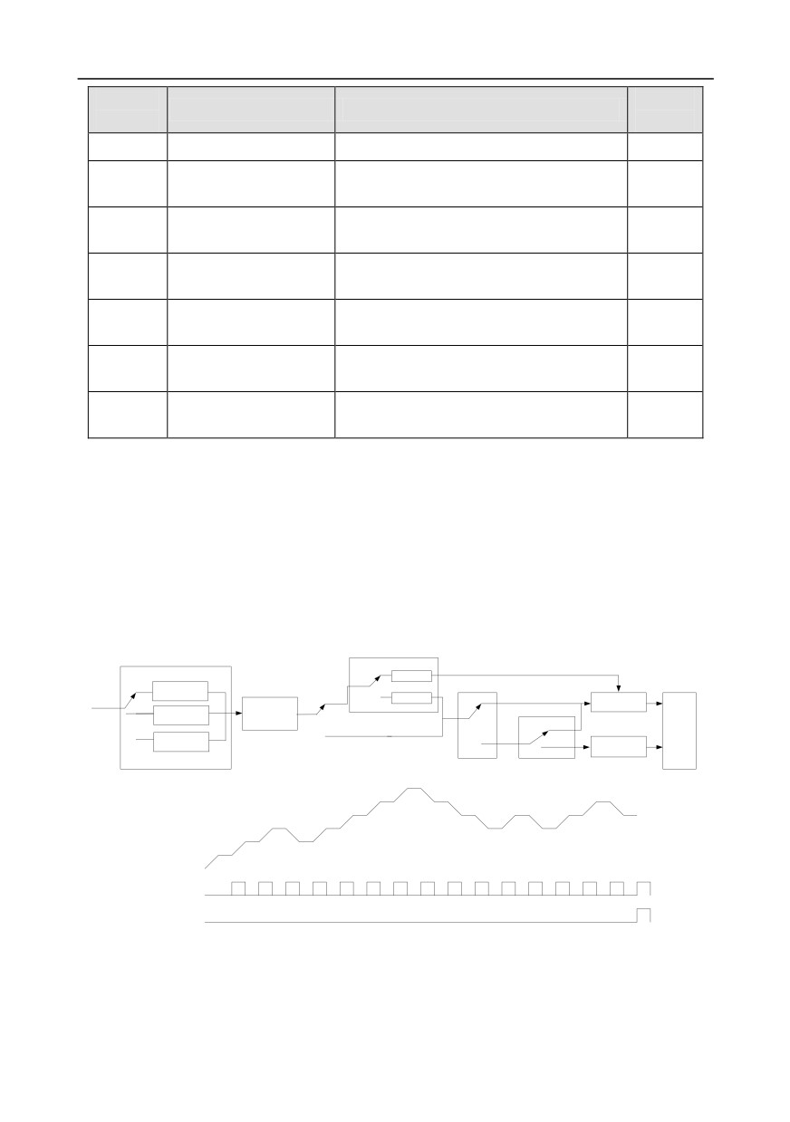
5.5.13 Simple PLC
Simple PLC is a multi-step speed generator, and the inverter can change the running frequency and
direction automatically based on the running time to fulfill process requirements. Previously, such
function was realized with external PLC, while now, the inverter itself can achieve this function.
GD350 series inverter can realize
16-step speeds control, and provide four groups of
acceleration/deceleration time for users to choose from.
After the set PLC completes one cycle (or one section), one ON signal can be output by the
multi-function relay.
P10.01 (simple PLC memory selection)
P10.00(simple PLC mode)
0
No memory
after power off
0
Stop after running
Power cut during
Set frequency
once
running
1
Memory after
Restart running
power off
0
after the first
1
Keep running in the
Setup of running
section
final value after
parameters of each
running once
PLC stage
Normal running
0
P17.00
2
Cyclic running
1
Continue running at
1
the frequency when
interruption occurred
PLC mode
P10.36
Terminal function 23
(PLC restart mode)
Simple PLC stop reset
Digital output 16
Simple PLC state completed
Digital output 17
Simple PLC cycle completed
-103-
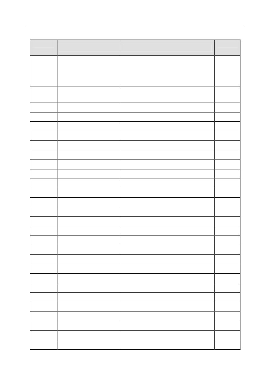
Chapter 5
Related parameter list:
Function
Default
Name
Detailed parameter description
code
value
0: Stop after running once
1: Keep running in the final value after
P10.00
Simple PLC mode
0
running once
2: Cyclic running
Simple PLC memory
0: No memory after power down
P10.01
0
selection
1: Memory after power down
P10.02
Multi-step speed 0
-100.0-100.0%
0.0%
P10.03
Running time of 0th step
0.0-6553.5s (min)
0.0s
P10.04
Multi-step speed 1
-100.0-100.0%
0.0%
P10.05
Running time of 1st step
0.0-6553.5s (min)
0.0s
P10.06
Multi-step speed 2
-100.0-100.0%
0.0%
P10.07
Running time of 2nd step
0.0-6553.5s (min)
0.0s
P10.08
Multi-step speed 3
-100.0-100.0%
0.0%
P10.09
Running time of 3rd step
0.0-6553.5s (min)
0.0s
P10.10
Multi-step speed 4
-100.0-100.0%
0.0%
P10.11
Running time of 4th step
0.0-6553.5s (min)
0.0s
P10.12
Multi-step speed 5
-100.0-100.0%
0.0%
P10.13
Running time of 5th step
0.0-6553.5s (min)
0.0s
P10.14
Multi-step speed 6
-100.0-100.0%
0.0%
P10.15
Running time of 6th step
0.0-6553.5s (min)
0.0s
P10.16
Multi-step speed 7
-100.0-100.0%
0.0%
P10.17
Running time of 7th step
0.0-6553.5s (min)
0.0s
P10.18
Multi-step speed 8
-100.0-100.0%
0.0%
P10.19
Running time of 8th step
0.0-6553.5s (min)
0.0s
P10.20
Multi-step speed 9
-100.0-100.0%
0.0%
P10.21
Running time of 9th step
0.0-6553.5s (min)
0.0s
P10.22
Multi-step speed 10
-100.0-100.0%
0.0%
P10.23
Running time of 10th step
0.0-6553.5s (min)
0.0s
P10.24
Multi-step speed 11
-100.0-100.0%
0.0%
P10.25
Running time of 11th step
0.0-6553.5s (min)
0.0s
P10.26
Multi-step speed 12
-100.0-100.0%
0.0%
P10.27
Running time of 12th step
0.0-6553.5s (min)
0.0s
-104-
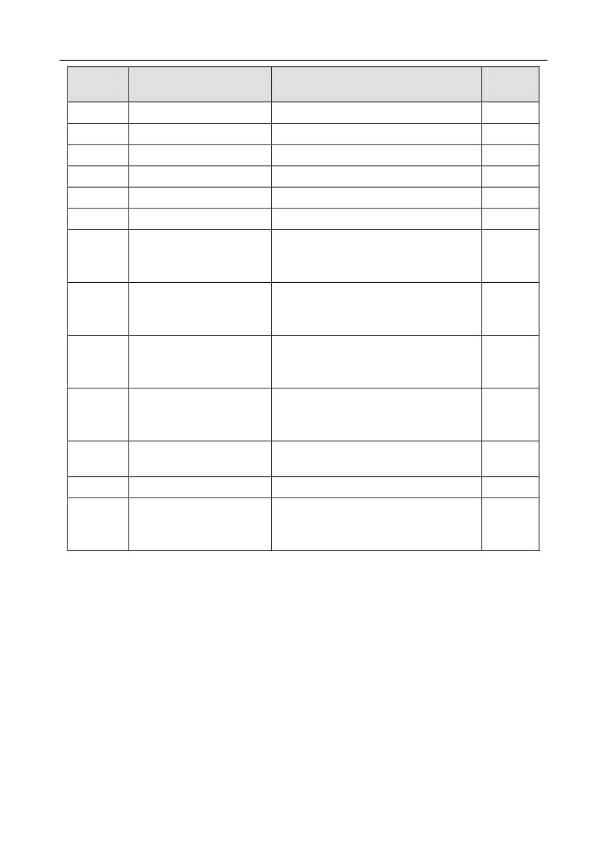
Chapter 5
Function
Default
Name
Detailed parameter description
code
value
P10.28
Multi-step speed 13
-100.0-100.0%
0.0%
P10.29
Running time of 13th step
0.0-6553.5s (min)
0.0s
P10.30
Multi-step speed 14
-100.0-100.0%
0.0%
P10.31
Running time of 14th step
0.0-6553.5s (min)
0.0s
P10.32
Multi-step speed 15
-100.0-100.0%
0.0%
P10.33
Running time of 15th step
0.0-6553.5s (min)
0.0s
0: Restart from the first section
P10.36
PLC restart mode
1: Continue running at the frequency
0
when interruption occurred
Acceleration/deceleration
P10.34
time of 0-7 stage of simple
0x0000-0XFFFF
0000
PLC
Acceleration/deceleration
P10.35
time of 8-15 stage of simple
0x0000-0XFFFF
0000
PLC
23: Simple PLC stop reset
P05.01-
Digital input function
24: Simple PLC pause
P05.09
25: PID control pause
P06.01-
16: Simple PLC stage reached
Digital output function
P06.04
17: Simple PLC cycle reached
P17.00
Set frequency
0.00Hz-P00.03 (max. output frequency)
0.00Hz
Simple PLC and current
P17.27
stage number of multi-step
0-15
0
speed
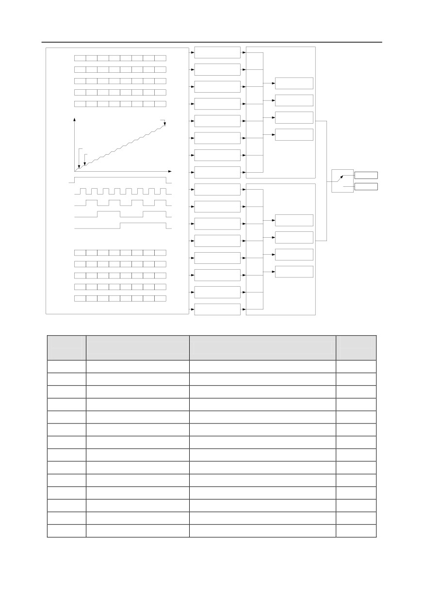
5.5.14 Multi-step speed running
Set the parameters used in multi-step speed running. GD350 inverter can set 16-step speeds, which
are selectable by multi-step speed terminals 1-4, corresponding to multi-step speed 0 to multi-step
speed 15.
-105-
Chapter 5
P10.02 multi-step speed 0
BIT0
P10.34
Terminal function 16
P10.03 running time of 0th step
BIT1
Acceleration/deceleration time
Multi-step speed
OFF
ON
OFF
ON
OFF
ON
OFF
ON
terminal 1
selection of 0-7 section of
Terminal function 17
P10.04 multi-step speed 1
BIT2
simple PLC
Multi-step speed
OFF
OFF
ON
ON
ON
OFF
OFF
ON
P10.05 running time of 1st step
BIT3
terminal 2
Terminal function 18
Multi-step speed
OFF
OFF
OFF
OFF
ON
ON
ON
ON
00
P00.10 acceleration time 1
terminal 3
P10.06 multi-step speed 2
BIT4
P00.12 deceleration time 1
Terminal function 19
P10.07 running time of 2nd step
BIT5
Multi-step speed
OFF
OFF
OFF
OFF
OFF
OFF
OFF
OFF
terminal 4
01
P08.00 acceleration time 2
Multi-step speed
0
1
2
3
4
5
6
7
P10.08 multi-step speed 3
BIT6
P08.01 deceleration time 2
P10.09 running time of 3rd step
BIT7
10
P08.02 acceleration time 3
Multi-step speed 15
P10.10 multi-step speed 4
BIT8
P08.03 deceleration time 3
P10.11 running time of 4th step
BIT9
11
P08.04 acceleration time 4
P10.12 multi-step speed 5
BIT10
P08.15 deceleration time 4
P10.13 running time of 5th step
BIT11
Multi-step speed 0
Multi-step speed 1
P10.14 multi-step speed 6
BIT12
P10.15 running time of 6th step
BIT13
P10.16 multi-step speed 7
BIT14
P10.17 running time of 7th step
BIT15
Valid
Frequency-hold
Running command
ON
OFF
Invalid
Multi-step speed
P10.18 multi-step speed 8
BIT0
P10.35
output
Terminal function 16
P10.19 running time of 8th step
BIT1
Acceleration/deceleration time
Multi-step speed
selection of 8-15 section of
terminal 1
simple PLC
Terminal function 17
Multi-step speed
P10.20 multi-step speed 9
BIT2
terminal 2
P10.21 running time of 9th step
BIT3
Terminal function 18
Multi-step speed
00
P00.10 acceleration time 1
terminal 3
P10.22 multi-step speed 10
BIT4
P00.12 deceleration time 1
Terminal function 19
P10.23 running time of 10th step
BIT5
Multi-step speed
terminal 4
01
P08.00 acceleration time 2
P10.24 multi-step speed 11
BIT6
P08.01 deceleration time 2
P10.25 running time of 11th step
BIT7
Terminal function 16
Multi-step speed
OFF
ON
OFF
ON
OFF
ON
OFF
ON
10
P08.02 acceleration time 3
terminal 1
P10.26 multi-step speed 12
BIT8
P08.03 deceleration time 3
Terminal function 17
P10.27 running time of 12th step
BIT9
Multi-step speed
OFF
OFF
ON
ON
ON
OFF
OFF
ON
terminal 2
11
P08.04 acceleration time 4
Terminal function 18
P10.28 multi-step speed 13
BIT10
P08.15 deceleration time 4
Multi-step speed
OFF
OFF
OFF
OFF
ON
ON
ON
ON
P10.29 running time of 13th step
BIT11
terminal 3
Terminal function 19
Multi-step speed
ON
ON
ON
ON
ON
ON
ON
ON
terminal 4
P10.30 multi-step speed 14
BIT12
P10.31 running time of 14th step
BIT13
Multi-step speed
8
9
10
11
12
13
14
15
P10.32 multi-step speed 15
BIT14
P10.33 running time of 15th step
BIT15
Related parameter list:
Functio
Default
Name
Detailed parameter description
n code
value
P10.02
Multi-step speed 0
-100.0-100.0%
0.0%
P10.03
Running time of 0th step
0.0-6553.5s (min)
0.0s
P10.04
Multi-step speed 1
-100.0-100.0%
0.0%
P10.05
Running time of 1st step
0.0-6553.5s (min)
0.0s
P10.06
Multi-step speed 2
-100.0-100.0%
0.0%
P10.07
Running time of 2nd step
0.0-6553.5s (min)
0.0s
P10.08
Multi-step speed 3
-100.0-100.0%
0.0%
P10.09
Running time of 3rd step
0.0-6553.5s (min)
0.0s
P10.10
Multi-step speed 4
-100.0-100.0%
0.0%
P10.11
Running time of 4th step
0.0-6553.5s (min)
0.0s
P10.12
Multi-step speed 5
-100.0-100.0%
0.0%
P10.13
Running time of 5th step
0.0-6553.5s (min)
0.0s
P10.14
Multi-step speed 6
-100.0-100.0%
0.0%
P10.15
Running time of 6th step
0.0-6553.5s (min)
0.0s
-106-
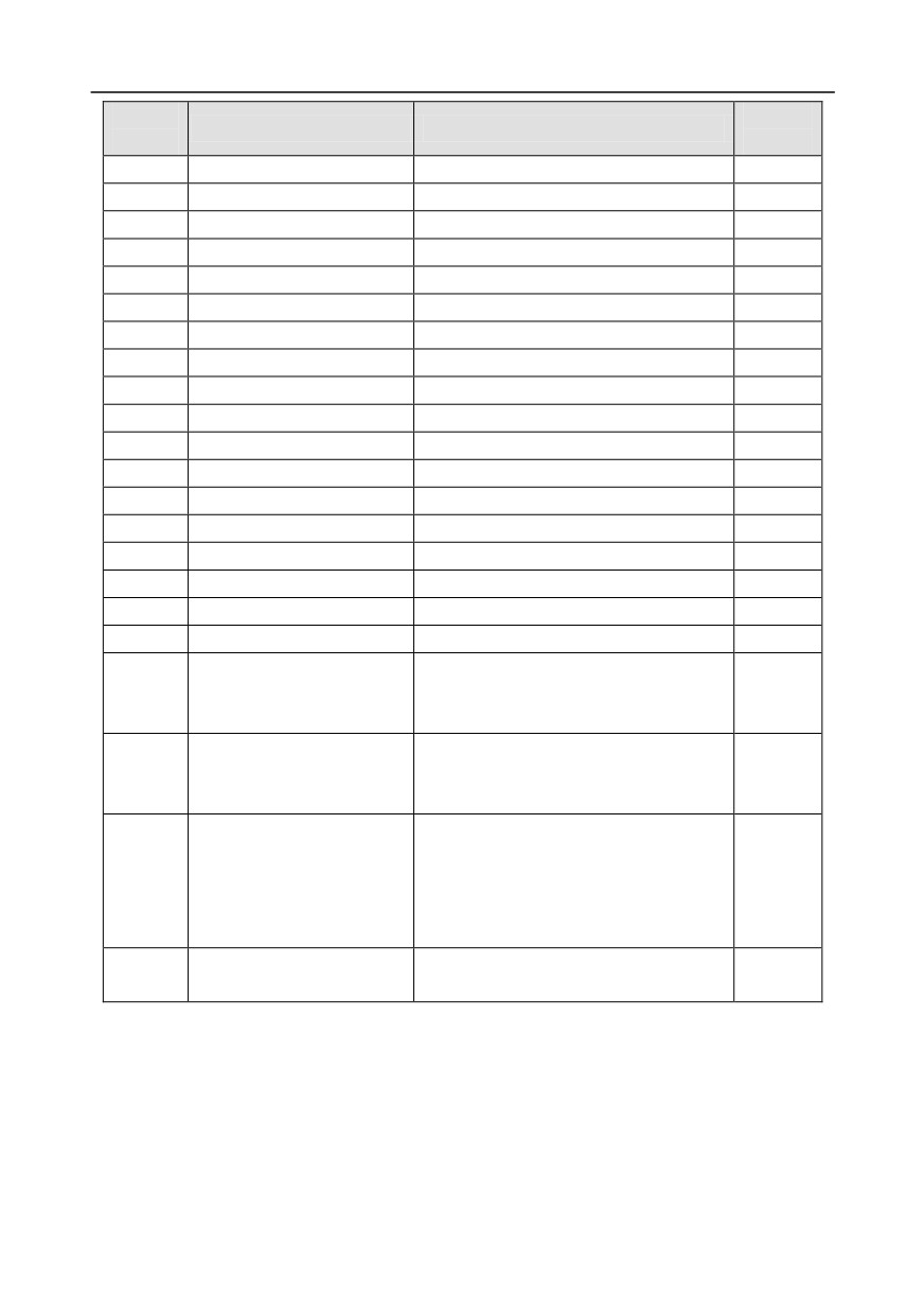
Chapter 5
Functio
Default
Name
Detailed parameter description
n code
value
P10.16
Multi-step speed 7
-100.0-100.0%
0.0%
P10.17
Running time of 7th step
0.0-6553.5s (min)
0.0s
P10.18
Multi-step speed 8
-100.0-100.0%
0.0%
P10.19
Running time of 8th step
0.0-6553.5s (min)
0.0s
P10.20
Multi-step speed 9
-100.0-100.0%
0.0%
P10.21
Running time of 9th step
0.0-6553.5s (min)
0.0s
P10.22
Multi-step speed 10
-100.0-100.0%
0.0%
P10.23
Running time of 10th step
0.0-6553.5s (min)
0.0s
P10.24
Multi-step speed 11
-100.0-100.0%
0.0%
P10.25
Running time of 11th step
0.0-6553.5s (min)
0.0s
P10.26
Multi-step speed 12
-100.0-100.0%
0.0%
P10.27
Running time of 12th step
0.0-6553.5s (min)
0.0s
P10.28
Multi-step speed 13
-100.0-100.0%
0.0%
P10.29
Running time of 13th step
0.0-6553.5s (min)
0.0s
P10.30
Multi-step speed 14
-100.0-100.0%
0.0%
P10.31
Running time of 14th step
0.0-6553.5s (min)
0.0s
P10.32
Multi-step speed 15
-100.0-100.0%
0.0%
P10.33
Running time of 15th step
0.0-6553.5s (min)
0.0s
Acceleration/decoration time
P10.34
selection of 0-7 section of
0x0000-0XFFFF
0000
simple PLC
Acceleration/decoration time
P10.35
selection of 8-15 section of
0x0000-0XFFFF
0000
simple PLC
16: Multi-step speed terminal 1
17: Multi-step speed terminal 2
P05.01-
Digital input function selection
18: Multi-step speed terminal 3
/
P05.09
19: Multi-step speed terminal 4
20: Multi-step speed pause
Simple PLC and current steps
0
P17.27
0-15
of multi-step speed
5.5.15 PID control
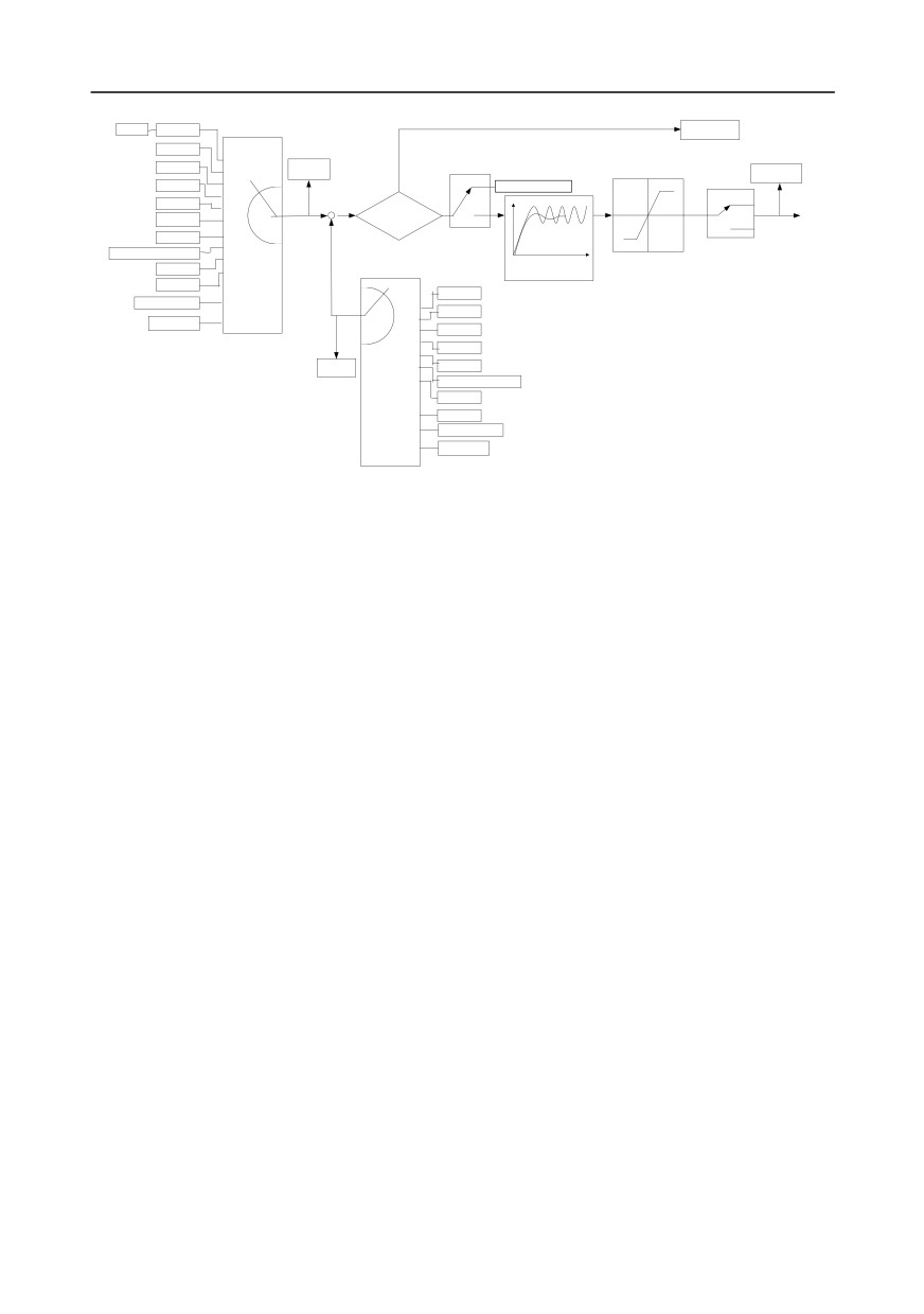
PID control, a common mode for process control, is mainly used to adjust the inverter output
frequency or output voltage through performing scale-division, integral and differential operations on
the difference between feedback signal of controlled variables and signal of the target, thus forming a
negative feedback system to keep the controlled variables above the target. It is suitable for flow
control, pressure control, temperature control, etc. Diagram of basic principles for output frequency
regulation is shown in the figure below.
-107-
Chapter 5
Pre-set PID reference of
keypad
P09.00
PID stops
P09.01
Keypad
(PID reference source)
adjustment
AI1
PID reference
value
Terminal function 25
P09.09
Set frequency
AI2
0
PID control pause
(upper limit value of PID
1
P17.23
Y
output)
P17.00
AI3
2
Valid
Keep current frequency
HDIA
3
0
4
+
Reference-
N
Invalid
Multi-stepspeed
5
feedback<P09.08?
1
PID output
MODBUS
6
-
7
P09.08 (Limit of PID control
P09.03
PROFIBUS\CANopen
deviation)
P09.10
(PID output characteristics)
8
P09.02
(lower limit value of PID
Ethernet
9
(PID feedback source)
output)
HDIB
Kp P09.04 (proportional gain)
AI1
EtherCat/Profinet
10
Ti P09.05 (integral time)
0
AI2
Td P09.06 (differential time)
PLC card
11
1
2
AI3
3
HDIA
4
P17.24
5
MODBUS
PID feedback
6
PROFIBUS\CANopen
value
7
Ethernet
8
HDIB
9
EtherCat/Profinet
10
PLC card
Introduction to the working principles and control methods for PID control
Proportional control
(Kp): When the feedback deviates from the reference, the output will be
proportional to the deviation, if such deviation is constant, the regulating variable will also be constant.
Proportional control can respond to feedback changes rapidly, however, it cannot eliminate the error
by itself. The larger the proportional gain, the faster the regulating speed, but too large gain will result
in oscillation. To solve this problem, first, set the integral time to a large value and the derivative time
to 0, and run the system by proportional control, and then change the reference to observe the
deviation between feedback signal and the reference (static difference), if the static difference is
(eg, increase the reference, and the feedback variable is always less than the reference after system
stabilizes), continue increasing the proportional gain, otherwise, decrease the proportional gain;
repeat such process until the static error becomes small.
Integral time (Ti): When feedback deviates from reference, the output regulating variable accumulates
continuously, if the deviation persists, the regulating variable will increase continuously until deviation
disappears. Integral regulator can be used to eliminate static difference; however, too large regulation
may lead to repetitive overshoot, which will cause system instability and oscillation. The feature of
oscillation caused by strong integral effect is that the feedback signal fluctuates up and down based
on the reference variable, and fluctuation range increases gradually until oscillation occurred. Integral
time parameter is generally regulated gradually from large to small until the stabilized system speed
fulfills the requirement.
Derivative time (Td): When the deviation between feedback and reference changes, output the
regulating variable which is proportional to the deviation variation rate, and this regulating variable is
only related to the direction and magnitude of the deviation variation rather than the direction and
magnitude of the deviation itself. Differential control is used to control the feedback signal variation
based on the variation trend. Differential regulator should be used with caution as it may easily
enlarge the system interferences, especially those with high variation frequency.
-108-
Chapter 5
When frequency command selection (P00.06, P00. 07) is 7, or channel of voltage setup (P04.27) is 6,
the running mode of inverter is process PID control.
5.5.15.1 General procedures for PID parameter setup
a. Determining proportional gain P
When determining proportional gain P, first, remove the integral term and derivative term of PID by
making Ti=0 and Td=0 (see PID parameter setup for details), thus turning PID into pure proportional
control. Set the input to 60%-70% of the max. allowable value, and increase proportional gain P
gradually from 0 until system oscillation occurred, and then in turn, decrease proportional gain P
gradually from current value until system oscillation disappears, record the proportional gain P at this
point and set the proportional gain P of PID to
60%-70% of current value. This is whole
commissioning process of proportional gain P.
b. Determine integral time Ti
After proportional gain P is determined, set the initial value of a larger integral time Ti, and decrease Ti
gradually until system oscillation occurred, and then in turn, increase Ti until system oscillation
disappears, record the Ti at this point, and set the integral time constant Ti of PID to 150%-180% of
current value. This is the commissioning process of integral time constant Ti.
c. Determining derivative time Td
The derivative time Td is generally set to 0.
If users need to set Td to another value, set in the same way with P and Ti, namely set Td to 30% of
the value when there is no oscillation.
d. Empty system load, perform load-carrying joint debugging, and then fine-tune PID parameter until
fulfilling the requirement.
5.5.15.2 How to fine-tune PID
After setting the parameters controlled by PID, users can fine-tune these parameters by the following
means.
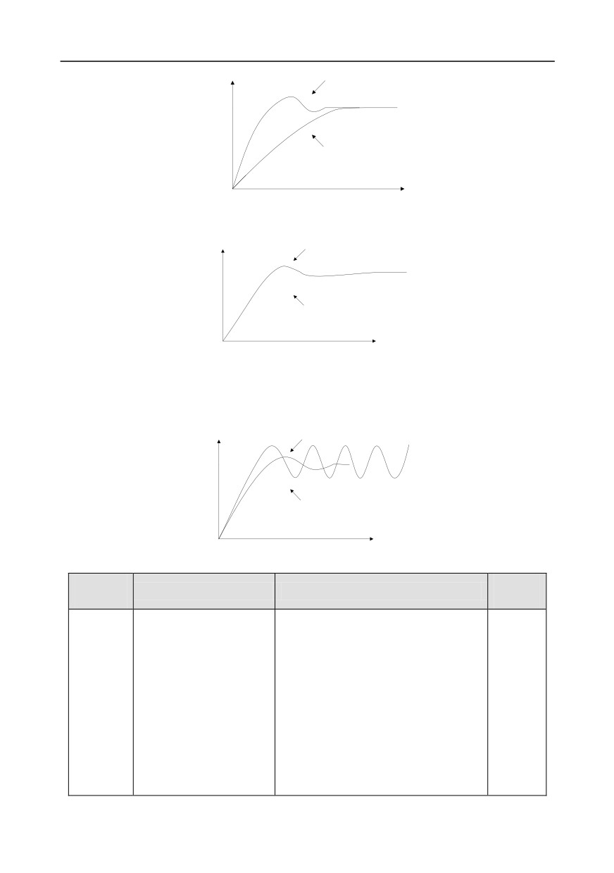
Control overmodulation: When overmodulation occurred, shorten the derivative time (Td) and
prolong integral time (Ti).
Response
Before adjustment
After adjustment
Time t
Stabilize the feedback value as fast as possible: when overmodulation occurred, shorten integral
time (Ti) and prolong derivative time (Td) to stabilize control as fast as possible.
-109-
Chapter 5
Response
After adjustment
Before adjustment
Time t
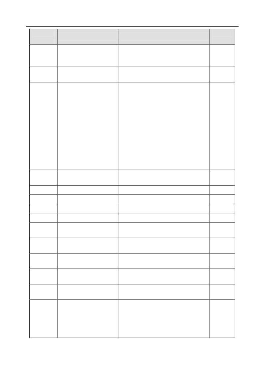
Control long-term vibration: If the cycle of periodic vibration is longer than the set value of integral
time (Ti), it indicates the integral action is too strong, prolong the integral time (Ti) to control vibration.
Response
Before adjustment
After adjustment
Time t
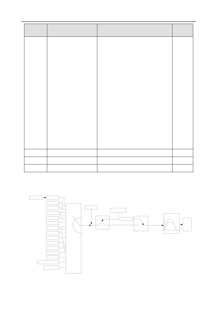
Control short-term vibration: If the vibration cycle is short is almost the same with the set value of
derivative time (Td), it indicates derivative action is too strong, shorten the derivative time (Td) to
control vibration. When derivative time (Td) is set to 0.00 (namely no derivative control), and there is
no way to control vibration, decrease the proportional gain.
Response
After adjustment
Before adjustment
Time t
Related parameter list:
Function
Default
Name
Detailed parameter description
code
value
0: Keypad (P09.01)
1: AI1
2: AI2
3: AI3
4: High-speed pulse HDIA
P09.00
PID reference source
5: Multi-step
0
6: MODBUS communication
7: PROFIBUS/CANopen/DeviceNet
communication
8: Ethernet communication
9: High-speed pulse HDIB
-110-
Chapter 5
Function
Default
Name
Detailed parameter description
code
value
10: EtherCat/Profinet communication
11: Programmable extension card
12: Reserved
Pre-set PID reference of
P09.01
-100.0%-100.0%
0.0%
keypad
0: AI1
1: AI2
2: AI3
3: High-speed pulse HDIA
4: MODBUS communication
5: PROFIBUS/CANopen/DeviceNet
P09.02
PID feedback source
0
communication
6: Ethernet communication
7: High-speed pulse HDIB
8: EtherCat/Profinet communication
9: Programmable extension card
10: Reserved
0: PID output is positive characteristic
P09.03
PID output characteristics
0
1: PID output is negative characteristic
P09.04
Proportional gain (Kp)
0.00-100.00
1.80
P09.05
Integral time (Ti)
0.01-10.00s
0.90s
P09.06
Derivative time (Td)
0.00-10.00s
0.00s
P09.07
Sampling cycle (T)
0.000-10.000s
0.100s
Limit of PID control
0.0-100.0%
P09.08
0.0%
deviation
Upper limit value of PID
P09.10-100.0%
(max. frequency
or
P09.09
100.0%
output
voltage)
Lower limit value of PID
-100.0%-P09.09
(max. frequency
or
P09.10
0.0%
output
voltage)
Feedback offline detection
0.0-100.0%
P09.11
0.0%
value
Feedback offline detection
0.0-3600.0s
P09.12
1.0s
time
0x0000-0x1111
Ones:
P09.13
PID control selection
0: Continue integral control after the
0x0001
frequency reaches upper/lower limit
1: Stop integral control after the
-111-
Chapter 5
Function
Default
Name
Detailed parameter description
code
value
frequency reaches upper/lower limit
Tens:
0: The same with the main reference
direction
1: Contrary to the main reference
direction
Hundreds:
0: Limit as per the max. frequency
1: Limit as per A frequency
Thousands:
0: A+B frequency, acceleration
/deceleration of main reference A
frequency source buffering is invalid
1: A+B frequency, acceleration/
deceleration of main reference A
frequency source buffering is valid,
acceleration/deceleration is determined
by P08.04 (acceleration time 4).
P17.00
Set frequency
0.00Hz-P00.03 (max. output frequency)
0.00Hz
P17.23
PID reference value
-100.0-100.0%
0.0%
P17.24
PID feedback value
-100.0-100.0%
0.0%
5.5.16 Run at wobbling frequency
Wobbling frequency is mainly applied in cases where transverse movement and winding functions are
needed like textile and chemical fiber industries. The typical working process is shown as below.
P00.10
Keypad
P00.06
Frequency set by
(A frequency command
AI1
selection)
Amplitude of wobbling
keypad
frequency
AI2
0
P08.05
1
Maintain current
frequency
AI3
2
3
HDIA
Valid
Set frequency
Valid
4
Simple PLC
*
Wobbling
5
*
Invalid
Invalid
frequency
6
output
Multi-step speed
7
Terminal function 26
PID
8
wobbling frequency
Terminal function 27
pause
Wobbling frequency reset
P00.11 acceleration time 1
MODBUS
9
P00.12 deceleration time 1
10
PROFIBUS
11
Ethernet
HDIB
AB pulse string
12
EtherCat/Profinet
13
PLC programmable
14
card
-112-
Chapter 5
Function
Default
Name
Detailed parameter description
code
value
P00.03
Max. output frequency
P00.03-400.00Hz
50.00Hz
0: Set via keypad
1: Set via AI1
2: Set via AI2
3: Set via AI3
4: Set via high speed pulse HDIA
5: Set via simple PLC program
6: Set via multi-step speed running
7: Set via PID control
A frequency command
P00.06
8: Set via MODBUS communication
0
selection
9: Set via PROFIBUS / CANopen /
DeviceNet communication
10: Set via Ethernet communication
11: Set via high speed pulse HDIB
12: Set via pulse string AB
13: Set via EtherCat/Profinet
communication
14: Set via PLC card
Depend
P00.11
Acceleration time 1
0.0-3600.0s
on model
Depend
P00.12
Deceleration time 1
0.0-3600.0s
on model
26: Wobbling frequency pause (stop at
P05.01-
Digital input function
current frequency)
/
P05.09
selection
27: Wobbling frequency reset (revert to
center frequency)
Amplitude of wobbling
P08.15
0.0-100.0% (relative to set frequency)
0.0%
frequency
0.0-50.0%
(relative to amplitude of
P08.16
Amplitude of jump frequency
0.0%
wobbling frequency)
Wobbling frequency rise
P08.17
0.1-3600.0s
5.0s
time
P08.18
Wobbling frequency fall time
0.1-3600.0s
5.0s
5.5.17 Local encoder input
GD350 series inverter supports pulse count function by inputting the count pulse from HDI high-speed
pulse port. When the actual count value is no less than the set value, digital output terminal will output
count-value-reached pulse signal, and the corresponding count value will be zeroed out.
-113-
Chapter 5
Function
Default
Name
Detailed parameter description
code
value
0x00-0x11
Ones: HDIA input type
0: HDIA is high-speed pulse input
P05.00
HDI input type
1: HDIA is digital input
0x00
Tens: HDIB input type
0: HDIB is high-speed pulse input
1: HDIB is digital input
0: Set input via frequency
HDIA high-speed pulse input
1: Reserved
P05.38
0
function
2: Input via encoder, used in combination
with HDIB
0: Set input via frequency
HDIB high-speed pulse input
1: Reserved
P05.44
0
function selection
2: Input via encoder, used in combination
with HDIA
0: PG card
P20.15
Speed measurement mode
1: local; realized by HDIA and HDIB;
0
supports incremental 24V encoder only
P18.00
Actual frequency of encoder
-999.9-3276.7Hz
0.0Hz
5.5.18 Commissioning procedures for position control and spindle positioning function
1. Commissioning procedures for closed-loop vector control of asynchronous motor
Step 1: Restore to default value via keypad
Step 2: Set P00.03, P00.04 and P02 group motor nameplate parameters
Step 3: Motor parameter autotuning
Carry out rotary parameter autotuning or static parameter autotuning via keypad, if the motor can be
disconnected from load, then it is users can carry out rotary parameter autotuning; otherwise, carry
out static parameter autotuning, the parameter obtained from autotuning will be saved in P02 motor
parameter group automatically.
Step 4: Verify whether the encoder is installed and set properly
a) Confirm the encoder direction and parameter setup
Set P20.01 (encoder pulse-per-revolution), set P00.00=2 and P00.10=20Hz, and run the inverter, at
this point, the motor rotates at 20Hz, observe whether the speed measurement value of P18.00 is
correct, if the value is negative, it indicates the encoder direction is reversed, under such situation, set
P20.02 to 1; if the speed measurement value deviates greatly, it indicates P20.01 is set improperly.
Observe whether P18.02 (encoder Z pulse count value) fluctuates, if yes, it indicates the encoder
suffers interference or P20.01 is set improperly, requiring users to check the wiring and the shielding
-114-