Goodrive350 Series High-performance Multi-function Inver ter. Operation manual - page 1
Goodrive350 Series
High-performance
Multi-function Inverter
Preface
Preface
Thank you for choosing Goodrive350 series inverter.
Goodrive350 is a high-performance and multipurpose inverter aiming to integrate synchronous motor
drive with asynchronous motor drive, and torque control, speed control with position control. It is
armed with advanced vector control technology and the latest digital processor dedicated for motor
control, thus enhancing product reliability and adaptability to the environment. Goodrive350 series
inverter adopts customized and industrialized design to realize excellent control performance through
optimized functions and flexible applications.
In order to meet diversified customer demands, Goodrive350 series inverter provides abundant
extension cards including programmable extension card, PG card, communication card and I/O
extension card to achieve various functions as needed.
The programmable extension card adopts mainstream CODESYS development environment for
customers to carry out secondary development easily, fulfilling varied customized needs and reducing
customer cost.
PG card supports a variety of encoders like incremental encoders and resolver-type encoders, in
addition, it also supports pulse reference and frequency-division output. PG card adopts digital filter
technology to improve EMC performance and to realize stable transmission of the encoder signal
over a long distance. It is equipped with encoder offline detection function to contain the impact of
system faults.
Goodrive350 series inverter supports multiple kinds of popular communication modes to realize
complicated system solutions. It can be connected to the internet with optional wireless
communication card, by which users can monitor the inverter state anywhere any time via mobile
APP.
Goodrive350 series inverter uses high power density design. Some power ranges carry built-in DC
reactor and brake unit to save installation space. Through overall EMC design, it can satisfy the low
noise and low electromagnetic interference requirements to cope with challenging grid, temperature,
humidity and dust conditions, thus greatly improving product reliability.
This operation manual presents installation wiring, parameter setup, fault diagnosis and trouble
shooting, and precautions related to daily maintenance. Read through this manual carefully before
installation to ensure Goodrive350 series inverter is installed and operated in a proper manner to give
full play to its excellent performance and powerful functions.
If the product is ultimately used for military affairs or manufacture of weapon, it will be listed on the
export control formulated by Foreign Trade Law of the People's Republic of China. Rigorous review
and necessary export formalities are needed when exported.
Our company reserves the right to update the information of our products.
i
Contents
Contents
Preface
i
Contents
ii
Chapter 1 Safety precautions
1
1.1 What this chapter contains
1
1.2 Safety definition
1
1.3 Warning symbols
1
1.4 Safety guidelines
2
Chapter 2 Quick startup
5
2.1 What this chapter contains
5
2.2 Unpack inspection
5
2.3 Application confirmation
5
2.4 Environment confirmation
5
2.5 Installation confirmation
6
2.6 Basic commissioning
6
Chapter 3 Product overview
8
3.1 What this chapter contains
8
3.2 Basic principle
8
3.3 Product specification
10
3.4 Product nameplate
12
3.5 Type designation key
12
3.6 Rated value
12
3.7 Structure diagram
14
Chapter 4 Installation guide
16
4.1 What this chapter contains
16
4.2 Mechanical installation
16
4.3 Standard wiring of main circuit
22
4.4 Standard wiring of control circuit
28
4.5 Wiring protection
31
Chapter 5 Basic operation instructions
33
5.1 What this chapter contains
33
5.2 Keypad introduction
33
5.3 Keypad display
36
5.4 Keypad operation
38
5.5 Basic operation instruction
51
Chapter 6 Function parameter list
124
6.1 What this chapter contains
124
6.2 Function parameter list
124
Chapter 7 Troubleshooting
227
7.1 What this chapter contains
227
7.2 Indications of alarms and faults
227
ii
Contents
7.3 Fault reset
227
7.4 Fault history
227
7.5 Inverter faults and solutions
227
7.6 Analysis on common faults
236
7.7 Countermeasures on common interference
243
Chapter 8 Maintenance and hardware fault diagnosis
247
8.1 What this chapter contains
247
8.2 Periodical inspection
247
8.3 Cooling fan
249
8.4 Capacitor
250
8.5 Power cable
252
Chapter 9 Communication protocol
253
9.1 What this chapter contains
253
9.2 Modbus protocol introduction
253
9.3 Application of Modbus
253
9.4 RTU command code and communication data
259
9.5 Common communication faults
274
Appendix A Extension cards
276
A.1 Model definition
276
A.2 Dimensions and installation
281
A.3 Wiring
284
A.4 IO extension card function description
284
A.5 PG extension card function description
286
A.6 Communication card function description
295
A.7 Programmable extension card function description
302
Appendix B Technical data
305
B.1 What this chapter contains
305
B.2 Derated application
305
B.3 Grid specifications
306
B.4 Motor connection data
306
B.5 Application standards
307
B.6 EMC regulations
307
Appendix C Dimension drawings
309
C.1 What this chapter contains
309
C.2 Keypad structure
309
C.3 Inverter structure
310
C.4 Dimensions of Inverters of AC 3PH 380V (-15%)-440V (+10%)
310
C.5 Dimensions of Inverters of AC 3PH 520V (-15%)-690V (+10%)
316
Appendix D Optional peripheral accessories
320
D.1 What this chapter contains
320
D.2 Wiring of peripheral accessories
320
iii
Contents
D.3 Power supply
322
D.4 Cables
322
D.5 Breaker and electromagnetic contactor
327
D.6 Reactors
329
D.7 Filters
332
D.8 Brake system
335
Appendix E STO function description
340
E.1 STO function logic table
340
E.2 STO channel delay description
340
E.3 STO function installation checklist
341
Appendix F Acronyms and abbreviations
342
Appendix G Further information
343
G.1 Product and service queries
343
G.2 Feedback on INVT Inverter manuals
343
G.3 Documents on the Internet
343
iv
Chapter 1
Chapter 1 Safety precautions
1.1 What this chapter contains
Read this manual carefully and follow all safety precautions before moving, installing, operating and
servicing the inverter. If these safety precautions are ignored, physical injury or death may occur, or
damage may occur to the equipment.
If any physical injury or death or damage to the equipment occur due to neglect of the safety
precautions in the manual, our company will not be responsible for any damages and we are not
legally bound in any manner.
1.2 Safety definition
Danger: Serious physical injury or even death may occur if related requirements are not followed
Warning: Physical injury or damage to the equipment may occur if related requirements are not
followed
Note: Procedures taken to ensure proper operation.
Qualified electricians: People working on the device should take part in professional electrical and
safety training, receive the certification and be familiar with all steps and requirements of installing,
commissioning, operating and maintaining the device to prevent any emergencies.
1.3 Warning symbols
Warnings caution you about conditions which can result in serious injury or death and/or damage to
the equipment, and advice on how to avoid the danger. Following warning symbols are used in this
manual.
Symbols
Name
Instruction
Abbreviation
Serious physical injury or even death
Danger
Danger
may occur if related requirements
are not followed
Physical injury or damage to the
Warning
Warning
equipment may occur if related
requirements are not followed
Damage to the PCBA board may
Electrostatic
Forbid
occur if related requirements are not
discharge
followed
The base of the inverter may
Hot
Hot sides
become hot. Do not touch.
As high voltage still presents in the
bus capacitor after power off, wait for
Electric
at least five minutes (or 15 min / 25
shock
min, depending on the warning
symbols on the machine) after power
-1-
Chapter 1
off to prevent electric shock
Read
Read the operation manual before
manual
operating on the equipment
Procedures taken to ensure proper
Note
Note
Note
operation
1.4 Safety guidelines
Only trained and qualified electricians are allowed to carry out related
operations.
Do not perform wiring, inspection or component replacement when power
supply is applied. Ensure all the input power supplies are disconnected
before wiring and inspection, and wait for at least the time designated on the
inverter or until the DC bus voltage is less than 36V. The minimum waiting
time is listed in the table below.
Inverter model
Minimum waiting time
380V
1.5kW-110kW
5 min
380V
132kW-315kW
15 min
380V
Above 355kW
25 min
660V
22kW-132kW
5 min
660V
160kW-350kW
15 min
660V
400kW-630kW
25 min
Do not refit the inverter unless authorized; otherwise, fire, electric shock or
other injuries may occur.
The base of the radiator may become hot during running. Do not touch to
avoid hurt.
The electrical parts and components inside the inverter are electrostatic.
Take measures to prevent electrostatic discharge during related operation.
1.4.1 Delivery and installation
Install the inverter on fire-retardant material and keep the inverter away from
combustible materials.
Connect the optional brake parts (brake resistors, brake units or feedback
units) according to the wiring diagram.
Do not operate on a damaged or incomplete inverter.
Do not touch the inverter with wet items or body parts; otherwise, electric
shock may occur.
Note:
Select appropriate tools for delivery and installation to ensure a safe and proper running of the
inverter and avoid physical injury or death. To ensure physical safety, the installation staff should
take mechanical protective measures like wearing exposure shoes and working uniforms;
Ensure to avoid physical shock or vibration during delivery and installation;
-2-
Chapter 1
Do not carry the inverter by its front cover only as the cover may fall off;
Installation site should be away from children and other public places;
The inverter cannot meet the requirements of low voltage protection in IEC61800-5-1 if the
altitude of installation site is above 2000m;
The inverter should be used in proper environment (see chapter 4.2.1 Installation environment
for details);
Prevent the screws, cables and other conductive parts from falling into the inverter;
As leakage current of the inverter during running may exceed 3.5mA, ground properly and
ensure the grounding resistance is less than 10Ω. The conductivity of PE grounding conductor is
the same with that of the phase conductor (with the same cross sectional area).
R, S and T are the power input terminals, and U, V and W are output motor terminals. Connect
the input power cables and motor cables properly; otherwise, damage to the inverter may occur.
1.4.2 Commissioning and running
Disconnect all power sources applied to the inverter before terminal wiring, and
wait for at least the time designated on the inverter after disconnecting the
power sources.
High voltage presents inside the inverter during running. Do not carry out any
operation on the inverter during running except for keypad setup.
The inverter may start up by itself when P01.21 (restart after power down) is set
to 1. Do not get close to the inverter and motor.
The inverter cannot be used as "Emergency-stop device".
The inverter cannot act as an emergency brake for the motor; it is a must to
install mechanical brake device.
During driving permanent magnet synchronous motor, besides
above-mentioned items, the following work must be done before installation
and maintenance.
1.
Disconnect all the input power sources including main power and control
power.
2.
Ensure the permanent-magnet synchronous motor has been stopped,
and the voltage on output end of the inverter is lower than 36V.
3.
After the permanent-magnet synchronous motor is stopped, wait for at
least the time designated on the inverter, and ensure the voltage
between "+" and "-" is lower than 36V.
4.
During operation, it is a must to ensure the permanent-magnet
synchronous motor cannot run again by the action of external load; it is
recommended to install effective external brake device or disconnect the
direct electrical connection between permanent-magnet synchronous
motor and the inverter.
Note:
Do not switch on or switch off input power sources of the inverter frequently;
-3-
Chapter 1
For inverters that have been stored for a long time, set the capacitance and carry out
inspection and pilot run on the inverter before use.
Close the front cover before running; otherwise, electric shock may occur.
1.4.3 Maintenance and component replacement
Only well-trained and qualified professionals are allowed to perform
maintenance, inspection, and component replacement on the inverter.
Disconnect all the power sources applied to the inverter before terminal
wiring, and wait for at least the time designated on the inverter after
disconnecting the power sources.
Take measures to prevent screws, cables and other conductive matters from
falling into the inverter during maintenance and component replacement.
Note:
Use proper torque to tighten the screws.
Keep the inverter and its parts and components away from combustible materials during
maintenance and component replacement.
Do not carry out insulation voltage-endurance test on the inverter, or measure the control
circuits of the inverter with megameter.
Take proper anti-static measures on the inverter and its internal parts during maintenance and
component replacement.
1.4.4 Scrap treatment
The heavy metals inside the inverter should be treated as industrial effluent.
When the life cycle ends, the product should enter the recycling system.
Dispose of it separately at an appropriate collection point instead of placing it
in the normal waste stream.
-4-
Chapter 2
Chapter 2 Quick startup
2.1 What this chapter contains
This chapter introduces the basic principles required during installation commissioning. Users can
realize quick installation commissioning by following these principles.
2.2 Unpack inspection
Check as follows after receiving products.
1. Check whether the packing box is damaged or dampened. If yes, contact local dealers or
INVT offices.
2. Check the model identifier on the exterior surface of the packing box is consistent with the
purchased model. If no, contact local dealers or INVT offices.
3. Check whether the interior surface of packing box is improper, for example, in wet
condition, or whether the enclosure of the inverter is damaged or cracked. If yes, contact
local dealers or INVT offices.
4. Check whether the nameplate of the inverter is consistent with the model identifier on the
exterior surface of the packing box. If not, contact local dealers or INVT offices.
5. Check whether the accessories (including user's manual, control keypad and extension
card units) inside the packing box are complete. If not, contact local dealers or INVT offices.
2.3 Application confirmation
Check the following items before operating on the inverter.
1. Verify the load mechanical type to be driven by the inverter, and check whether overload
occurred to the inverter during actual application, or whether the inverter power class needs
to be enlarged?
2. Check whether the actual running current of load motor is less than rated inverter current.
3. Check whether the control precision required by actual load is the same with the control
precision provided by the inverter.
4. Check whether the grid voltage is consistent with rated inverter voltage.
5. Check whether the functions required need an optional extension card to be realized.
2.4 Environment confirmation
Check the following items before use.
1. Check whether the ambient temperature of the inverter during actual application exceeds
40°C, if yes, derate 1% for every additional 1°C. In addition, do not use the inverter when
the ambient temperature exceeds 50°C.
Note: For cabinet-type inverter, its ambient temperature is the air temperature inside the
cabinet.
2. Check whether ambient temperature of the inverter during actual application is below
-10°C, if yes, install heating facility.
Note: For cabinet-type inverter, its ambient temperature is the air temperature inside the
-5-
Chapter 2
cabinet.
3. Check whether the altitude of the application site exceeds 1000m, if yes, derate 1% for
every additional 100 m.
4. Check whether the humidity of application site exceeds 90%, if yes, check whether
condensation occurred, if condensation does exist, take additional protective measures.
5. Check whether there is direct sunlight or animal intrusion in the application site, if yes, take
additional protective measures.
6. Check whether there is dust, explosive or combustible gases in the application site, if yes,
take additional protective measures.
2.5 Installation confirmation
After the inverter is installed properly, check the installation condition of the inverter.
Chapter 1 Check whether the input power cable and current-carrying capacity of the motor
cable fulfill actual load requirements.
Chapter 2 Check whether peripheral accessories (including input reactors, input filters, output
reactors, output filters, DC reactors, brake units and brake resistors) of the inverter are of
correct type and installed properly; check whether the installation cables fulfill
requirements on current-carrying capacity.
Chapter 3 Check whether the inverter is installed on fire-retardant materials; check whether the
hot parts (reactors, brake resistors, etc.) are kept away from combustible materials.
Chapter 4 Check whether all the control cables are routed separately with power cables based
on EMC requirement.
Chapter 5 Check whether all the grounding systems are grounded properly according to
inverter requirements.
Chapter 6 Check whether installation spacing of the inverter complies with the requirements in
operation manual.
Chapter 7 Check whether installation mode of the inverter complies with the requirements in
operation manual. Vertical installation should be adopted whenever possible.
Chapter 8 Check whether external connecting terminals of the inverter are firm and tight
enough, and whether the moment is up to the requirement.
Chapter 9 Check whether there are redundant screws, cables or other conductive objects
inside the inverter, if yes, take them out.
2.6 Basic commissioning
Carry out basic commissioning according to the following procedures before operating on the
inverter.
Chapter 1 Select motor type, set motor parameters and select inverter control mode according
to actual motor parameters.
Chapter 2 Whether autotuning is needed? If possible, disconnect the motor load to carry out
dynamic parameter autotuning; if the load cannot be disconnected, perform static
autotuning.
-6-
Chapter 2
Chapter 3 Adjust the acceleration and deceleration time based on actual working conditions of
the load.
Chapter 4 Jogging to carry out device commissioning. Check whether the motor running
direction is consistent with the direction required, if no, it is recommended to change the
motor running direction by exchanging the motor wiring of any two phases.
Chapter 5 Set all the control parameters, and carry out actual operation.
-7-
Chapter 3
Chapter 3 Product overview
3.1 What this chapter contains
This chapter mainly introduces the operation principles, product features, layouts, nameplates and
model instructions.
3.2 Basic principle
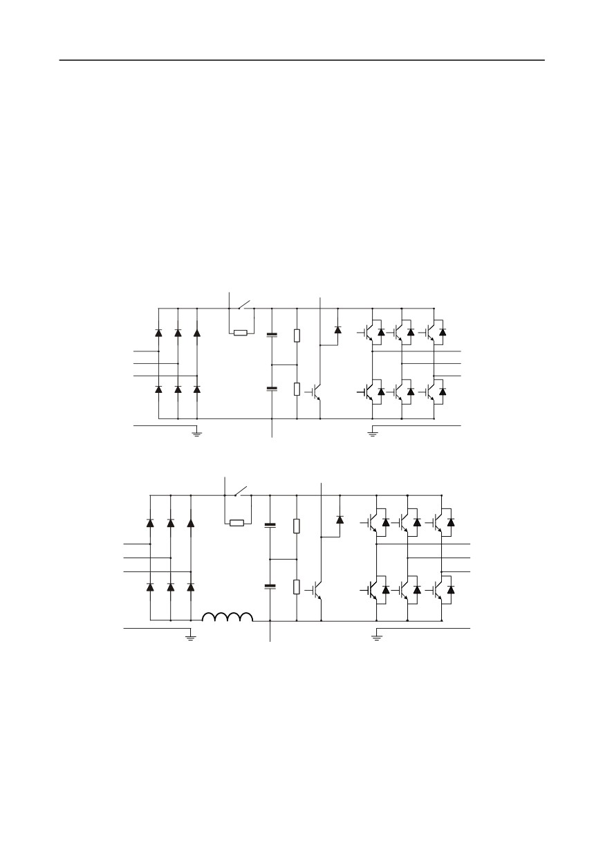
Goodrive350 series inverter is used to control asynchronous AC induction motor and
permanent-magnet synchronous motor. The figure below shows the main circuit diagram of the
inverter. The rectifier converts
3PH AC voltage into DC voltage, and the capacitor bank of
intermediate circuit stabilizes the DC voltage. The inverter converts DC voltage into the AC voltage
used by AC motor. When the circuit voltage exceeds the max. limit value, external brake resistor will
be connected to intermediate DC circuit to consume the feedback energy.
PB
(+)
R
U
S
V
T
W
PE
PE
(-)
Fig 3.1 380V (15kW and below) main circuit diagram
PB
(+)
R
U
S
V
T
W
PE
PE
(-)
Fig 3.2 380V (18.5kW-110kW (inclusive) ) main circuit diagram
-8-
Chapter 3
DC reactor
(+)
P1
R
U
S
V
T
W
PE
PE
(-)
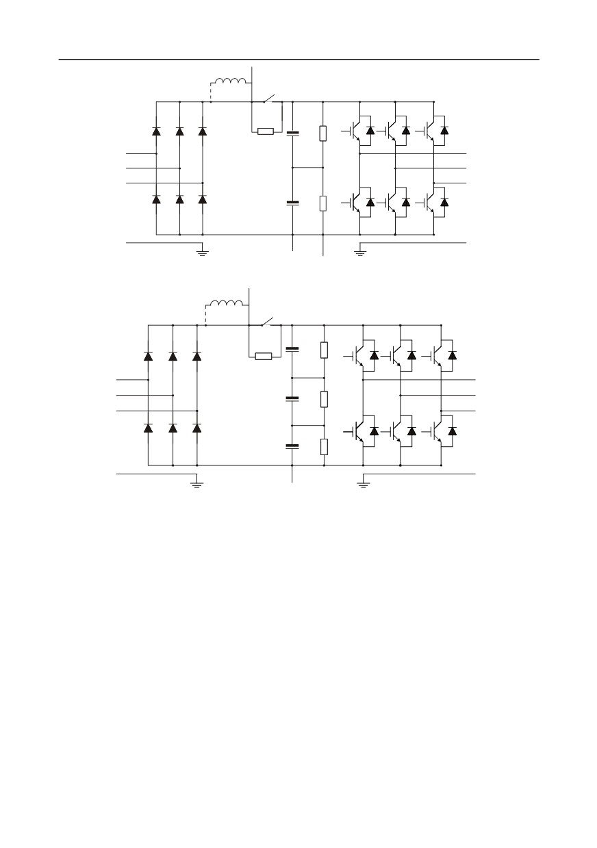
Fig 3.3 380V (132kW and above) main circuit diagram
DC reactor
(+)
P1
R
U
S
V
T
W
PE
PE
(-)
Fig 3.4 660V main circuit diagram
Note:
1.
132kW and above inverters can be connected to external DC reactors. Before connection, it is
required to take off the copper bar between P1 and (+). 132kW and above inverters can be
connected to external brake unit. DC reactors and brake units are optional parts.
2.
18.5kW-110kW (inclusive) inverters are equipped with built-in DC reactor.
3.
37kW and below models carry built-in brake units, 45kW-110kW (inclusive) supports built-in
brake unit. The models that carry built-in brake unit can also be connected to external brake
resistor. The brake resistor is optional part.
4.
660V inverters can be connected to external DC reactor. Before connection, it is required to take
off the copper bar between P1 and (+). 660V inverters can be connected to external brake unit.
DC reactors and brake units are optional parts.
-9-
Chapter 3
3.3 Product specification
Function description
Specification
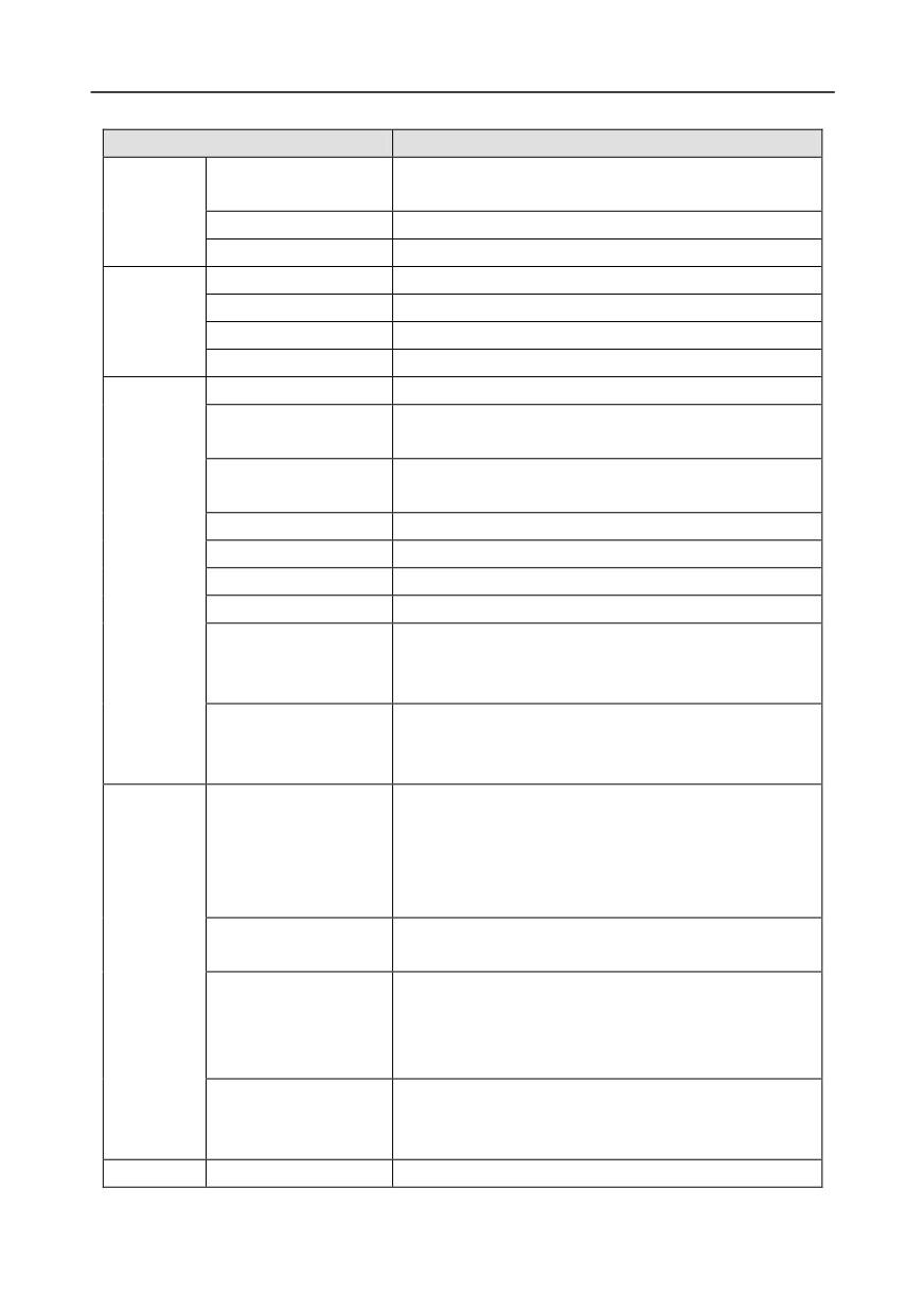
AC 3PH 380V (-15%)-440V (+10%) rated voltage: 380V
Input voltage (V)
AC 3PH 520V (-15%)-690V (+10%) rated voltage: 660V
Power input
Input current (A)
Refer to Rated value
Input frequency (Hz)
50Hz or 60Hz, allowable range: 47-63Hz
Output voltage (V)
0-input voltage
Power
Output current (A)
Refer to Rated value
output
Output power (kW)
Refer to Rated value
Output frequency (Hz)
0-400Hz
Control mode
SVPWM control, SVC, VC
Asynchronous motor, permanent-magnet synchronous
Motor type
motor
Asynchronous motor 1: 200 (SVC); Synchronous motor 1:
Speed regulation ratio
20 (SVC) , 1:1000 (VC)
Speed control precision
±0.2% (SVC), ±0.02% (VC)
Technical
Speed fluctuation
± 0.3% (SVC)
control
Torque response
<20ms SVC) , <10ms (VC)
performance
Torque control precision
10% (SVC) , 5% (VC)
Asynchronous motor: 0.25Hz/150% (SVC)
Starting torque
Synchronous motor: 2.5 Hz/150% (SVC)
0Hz/200% (VC)
150% of rated current: 1min;
Overload capacity
180% of rated current: 10s;
200% of rated current: 1s;
Digital, analog, pulse frequency, multi-step speed
running, simple PLC, PID, MODBUS communication,
Frequency setup mode
PROFIBUS communication, etc;
Realize switch-over between the set combination and the
set channel
Automatic voltage
Keep the output voltage constant when grid voltage
Running
regulation function
changes
control
Fault protection function
performance
Provide over 30 kinds of fault protection functions:
Fault protection function
overcurrent, overvoltage, undervoltage,
over-temperature, phase loss and overload, etc
Realize impact-free starting of the motor in rotating
Speed tracking restart
Note: This function is available for
4kW and above
function
models
Peripheral
Terminal analog input
No more than 20mV
-10-
Chapter 3
Function description
Specification
interface
resolution
Terminal digital input
No more than 2ms
resolution
Analog input
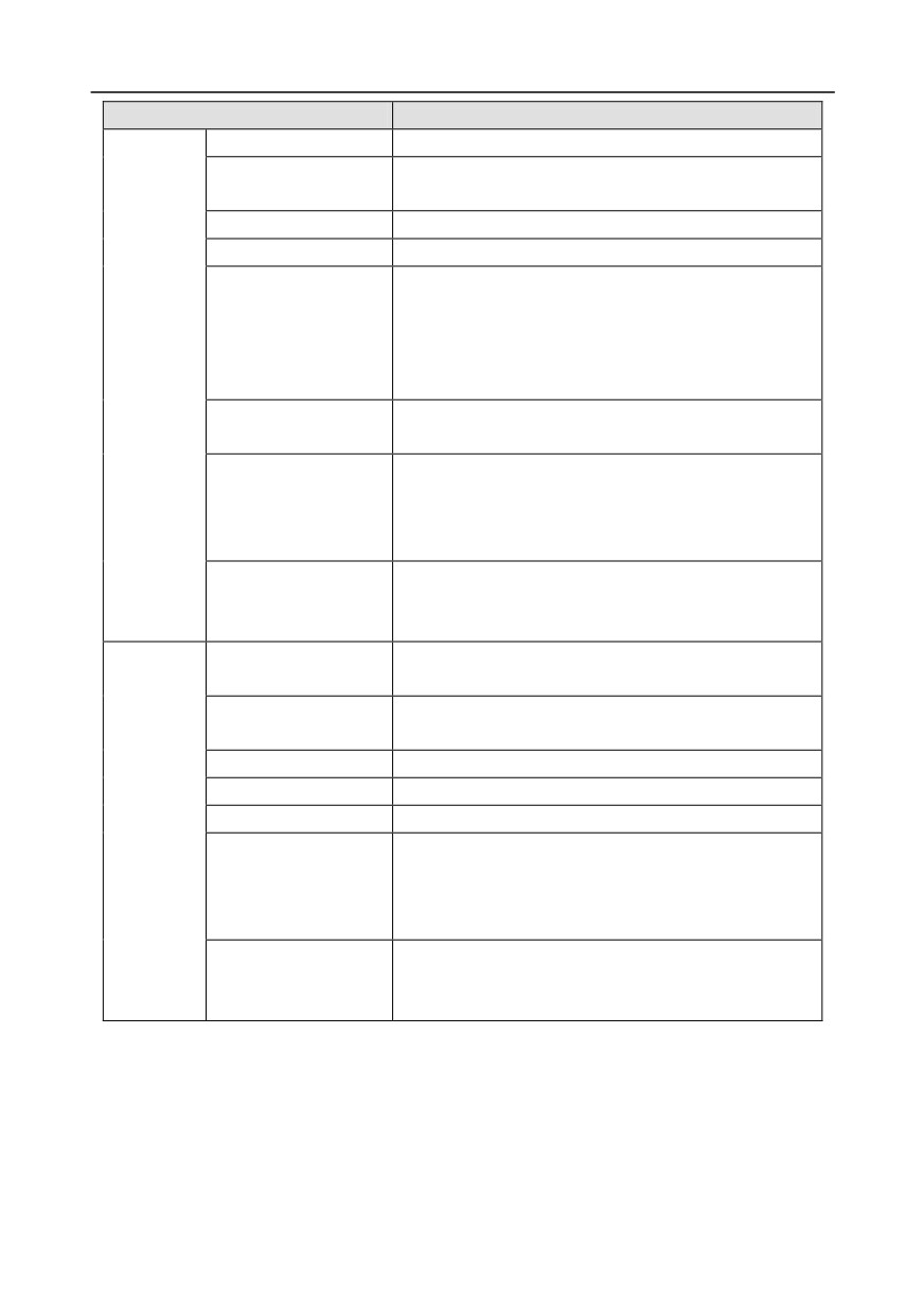
2 inputs, AI1: 0-10V/0-20mA; AI2: -10-10V
Analog output
1 output, AO1: 0-10V /0-20mA
Four regular inputs; max. frequency:
1kHz; internal
impedance: 3.3kΩ
Digital input
Two high-speed inputs; max. frequency: 50kHz; supports
quadrature encoder input; with speed measurement
function
One high-speed pulse output; max. frequency: 50kHz
Digital output
One Y terminal open collector output
Two programmable relay outputs
RO1A NO, RO1B NC, RO1C common port
Relay output
RO2A NO, RO2B NC, RO2C common port
Contact capacity: 3A/AC250V, 1A/DC30V
Three extension interfaces: SLOT1, SLOT2, SLOT3
Extension interface
Expandable PG card, programmable extension card,
communication card, I/O card, etc
Support wall-mounting, floor-mounting and
Installation mode
flange-mounting
Temperature of running
-10-50°C, derating is required if the ambient temperature
environment
exceeds 40°C
Protection level
IP20
Pollution level
Level 2
Cooling mode
Air cooling
Others
Built-in brake unit for 380V 37kW and below models;
Optional built-in brake unit for 380V 45kW-110kW
Brake unit
(inclusive) models;
Optional external brake unit for 660V models;
380V models fulfill the requirements of IEC61800-3 C3
EMC filter
Optional external filter should meet the requirements of
IEC61800-3 C2
-11-
Chapter 3
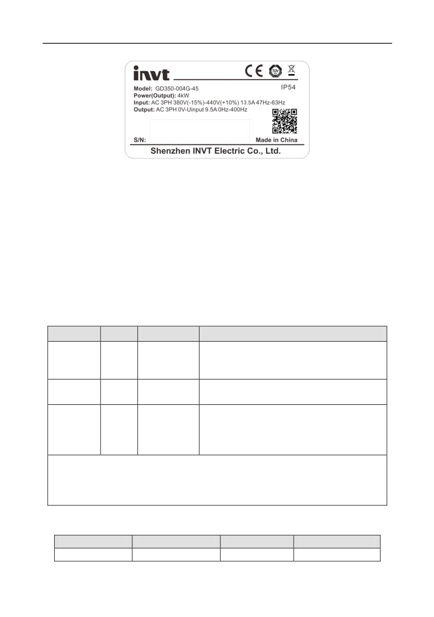
3.4 Product nameplate
Fig 3.5 Product nameplate
Note:
1. This is an example of the nameplate of standard Goodrive350 products. The CE/TUV/IP20
marking on the top right will be marked according to actual certification conditions.
2. Scan the QR code on the bottom right to download mobile APP and operation manual.
3.5 Type designation key
The type designation key contains product information. Users can find the type designation key on
the nameplate and simple nameplate of the inverter.
GD350 - 5R5G - 4
①
②
③
Fig 3.6 Type designation key
Field
Sign
Description
Contents
Abbreviation
Abbreviation of
GD350: Goodrive350 high-performance
of product
①
product series
multi-function inverter
series
Power range +
5R5-5.5kW
Rated power
②
load type
G—Constant torque load
4: AC 3PH 380V (-15%)-440V (+10%)
Rated voltage: 380V
Voltage level
③
Voltage level
6: AC 3PH 520V (-15%)-690V (+10%)
Rated voltage: 660V
Note:
Built-in brake unit is included in standard configuration of 380V 37kW and below models;
Brake unit is not included in standard configuration of 380V 45-110kW models (optional built-in
brake unit is available, suffix "-B" indicates optional built-in brake unit, eg GD350-045G-4-B)
3.6 Rated value
3.6.1 AC 3PH 380V(-15%)-440V(+10%) rated value
Product model
Output power (kW)
Input current (A)
Output current (A)
GD350-1R5G-4
1.5
5.0
3.7
-12-
Chapter 3
Product model
Output power (kW)
Input current (A)
Output current (A)
GD350-2R2G-4
2.2
5.8
5
GD350-004G-4
4
13.5
9.5
GD350-5R5G-4
5.5
19.5
14
GD350-7R5G-4
7.5
25
18.5
GD350-011G-4
11
32
25
GD350-015G-4
15
40
32
GD350-018G-4
18.5
47
38
GD350-022G-4
22
51
45
GD350-030G-4
30
70
60
GD350-037G-4
37
80
75
GD350-045G-4
45
98
92
GD350-055G-4
55
128
115
GD350-075G-4
75
139
150
GD350-090G-4
90
168
180
GD350-110G-4
110
201
215
GD350-132G-4
132
265
260
GD350-160G-4
160
310
305
GD350-185G-4
185
345
340
GD350-200G-4
200
385
380
GD350-220G-4
220
430
425
GD350-250G-4
250
460
480
GD350-280G-4
280
500
530
GD350-315G-4
315
580
600
GD350-355G-4
355
625
650
GD350-400G-4
400
715
720
GD350-450G-4
450
840
820
GD350-500G-4
500
890
860
Note:
1. The input current of 1.5-500kW inverter is measured in cases where the input voltage is 380V
without additional reactors;
2. The rated output current is the output current when the output voltage is 380V;
3. Within allowable input voltage range, the output current/power cannot exceed rated output
current/power.
3.6.2 AC 3PH 520V (-15%)-690V (+10%) rated value
Product model
Output power (kW)
Input current (A)
Output current (A)
GD350-022G-6
22
35
27
GD350-030G-6
30
40
34
GD350-037G-6
37
47
42
-13-
Chapter 3
Product model
Output power (kW)
Input current (A)
Output current (A)
GD350-045G-6
45
52
54
GD350-055G-6
55
65
62
GD350-075G-6
75
85
86
GD350-090G-6
90
95
95
GD350-110G-6
110
118
131
GD350-132G-6
132
145
147
GD350-160G-6
160
165
163
GD350-185G-6
185
190
198
GD350-200G-6
200
210
216
GD350-220G-6
220
230
240
GD350-250G-6
250
255
274
GD350-280G-6
280
286
300
GD350-315G-6
315
334
328
GD350-355G-6
355
360
380
GD350-400G-6
400
411
426
GD350-450G-6
450
445
465
GD350-500G-6
500
518
540
GD350-560G-6
560
578
600
GD350-630G-6
630
655
680
GD350-800G-6
800
822
860
GD350-2000G-6
2000
2072
2160
Note:
1. The input current of 22-350kW inverter is measured in cases where the input voltage is 660V
without DC reactors and input/output reactors;
2. The input current of 400-630kW inverter is measured in cases where the input voltage is 660V
and there is input reactor;
3. Rated output current is the output current when the output voltage is 660V.
4. Within allowable input voltage range, the output current/power cannot exceed rated output
current/power.
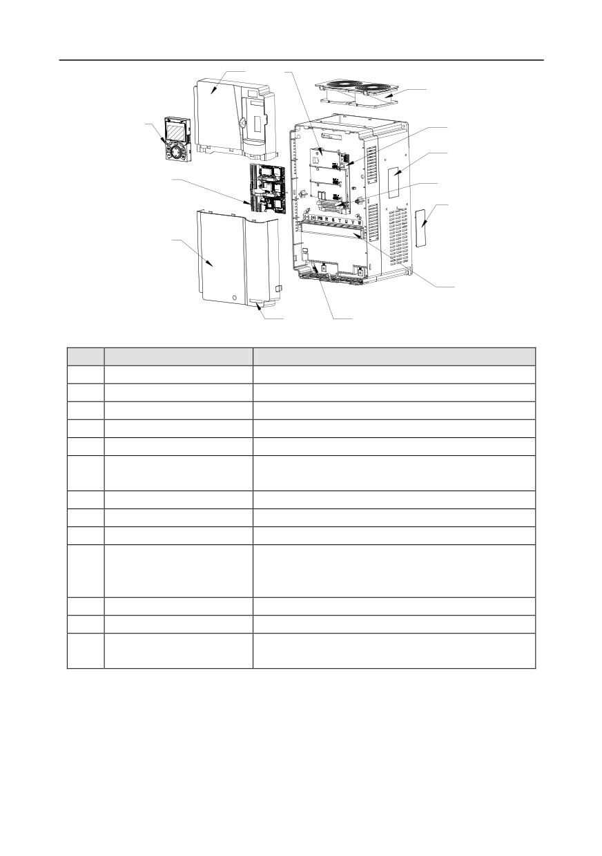
3.7 Structure diagram
The inverter layout is shown in the figure below (take a 380V 30kW inverter as an example).
-14-
Chapter 3
1
5
6
2
7
8
4
9
10
3
11
13
12
Fig 3.7 Structure diagram
No.
Name
Instruction
1
Upper cover
Protect internal components and parts
2
Keypad
See details at chapter 5.4 Keypad operation
3
Lower cover
Protect internal components and parts
4
Extension card
Optional, see details at Appendix A Extension cards
5
Baffle of control board
Protect the control board and install extension card
See details at chapter 9 Maintenance and hardware fault
6
Cooling fan
diagnosis
7
Keypad interface
Connect the keypad
8
Nameplate
See details at chapter 3.4 Product nameplate
9
Control terminals
See details at chapter 4 Installation guide
Optional. Cover plate can upgrade protection level,
Cover plate of heat emission
10
however, as it will also increase internal temperature,
hole
derated use is required.
11
Main circuit terminal
See details at chapter 4 Installation guide
12
POWER indicator
Power indicator
Label of GD350 product
13
See details at Type designation key of this chapter
series
-15-
Chapter 4
Chapter 4 Installation guide
4.1 What this chapter contains
This chapter introduces the mechanical and electrical installations of the inverter.
Only well trained and qualified professionals are allowed to carry out the
operations mentioned in this chapter. Please carry out operations according
to instructions presented in Safety precautions. Ignoring these safety
precautions may lead to physical injury or death, or device damage.
Ensure the inverter power is disconnected before installation. If the inverter
has been powered on, disconnect the inverter and wait for at least the time
designated on the inverter, and ensure the POWER indicator is off. Users are
recommended to use a multimeter to check and ensure the inverter DC bus
voltage is below 36V.
Installation must be designed and done according to applicable local laws
and regulations. INVT does not assume any liability whatsoever for any
installation which breaches local laws and regulations. If recommendations
given by INVT are not followed, the inverter may experience problems that
the warranty does not cover.
4.2 Mechanical installation
4.2.1 Installation environment
Installation environment is essential for the inverter to operate at its best in the long run. The
installation environment of the inverter should meet the following requirements.
Environment
Condition
Installation
Indoors
site
-10-+50°C;
When the ambient temperature exceeds 40°C, derate 1% for every
additional 1°C;
It is not recommended to use the inverter when the ambient temperature
is above 50°C;
In order to improve reliability, do not use the inverter in cases where the
Ambient
temperature changes rapidly;
temperature
When the inverter is used in a closed space eg control cabinet, use
cooling fan or air conditioner to prevent internal temperature from
exceeding the temperature required;
When the temperature is too low, if restart an inverter which has been
idled for a long time, it is required to install external heating device before
use to eliminate the freeze inside the inverter, failing to do so may cause
damage to the inverter.
Humidity
The relative humidity (RH) of the air is less than 90%;
-16-

Chapter 4
Environment
Condition
Condensation is not allowed;
The max RH cannot exceed 60% in the environment where there are
corrosive gases.
Storage
-30-+60°C
temperature
The installation site should meet the following requirements.
Away from electromagnetic radiation sources;
Away from oil mist, corrosive gases and combustible gases;
Ensure foreign object like metal powder, dust, oil and water will not fall
Running
into the inverter (do not install the inverter onto combustible object like
environment
wood);
Away from radioactive substance and combustible objects;
Away from harmful gases and liquids;
Low salt content;
No direct sunlight
Below 1000m;
When the altitude exceeds 1000m, derate 1% for every additional 100m;
Altitude
When the altitude exceeds 2000m, configure isolation transformer on the
input end of the inverter. It is recommended to keep the altitude below
5000m.
Vibration
The max. amplitude of vibration should not exceed 5.8m/s2 (0.6g)
Installation
Install the inverter vertically to ensure good heat dissipation effect
direction
Note:
1. GD350 series inverter should be installed in a clean and well-ventilated environment based
on the IP level.
2. The cooling air must be clean enough and free from corrosive gases and conductive dust.
4.2.2 Installation direction
The inverter can be installed on the wall or in a cabinet.
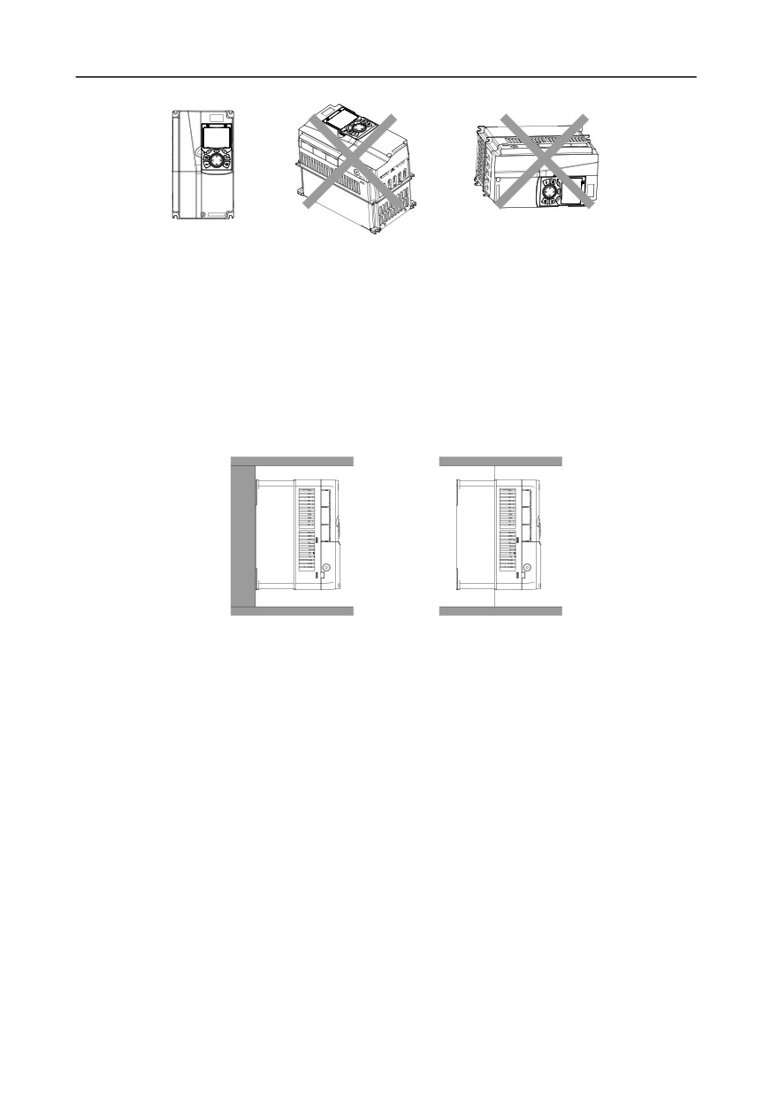
The inverter must be installed vertically. Check the installation position according to following
requirements. See appendix C Dimension drawings for detailed outline dimensions.
-17-
Chapter 4
OK
NG
NG
A. Vertical installation
B. Horizontal installation
C. Transverse installation
Fig 4.1 Installation direction of the inverter
4.2.3 Installation mode
There are three kinds of installation modes based on different inverter dimensions.
1. Wall-mounting: suitable for 380V 315kW and below inverters, and 660V 355kW and below
inverters;
2. Flange-mounting: suitable for 380V 200kW and below inverters, and 660V 220kW and below
inverters;
3. Floor-mounting: suitable for 380V 220-500kW inverters, and 660V 250-630kW inverters.
Wall-mounting
Flange-mounting
Fig 4.2 Installation mode
(1) Mark the position of the installation hole. See appendix for the position of installation hole;
(2) Mount the screws or bolts onto the designated position;
(3) Put the inverter on the wall;
(4) Tighten the fixing screws on the wall.
Note:
1.
Flange-mounting plate is a must for 380V 1.5-75kW inverters that adopt flange-mounting
mode; while 380V 90-200kW and 660V 22-220kW models need no flange-mounting plate.
2.
Optional installation base is available for 380V 220-315kW and 660V 250-355kW inverters.
The base can hold an input AC reactor (or DC reactor) and an output AC reactor.
-18-
Chapter 4
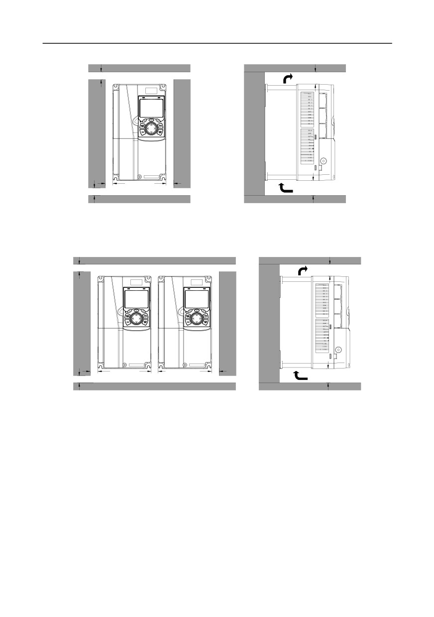
4.2.4 Single-unit installation
A
Hot air C
B
B
Cold air C
A
Fig 4.3 Single-unit installation
Note: The min. dimension of B and C is 100mm.
4.2.5 Multiple-unit installation
A
Hot air C
D
B
Cold air
C
A B
Fig 4.4 Parallel installation
Note:
1. When users install inverters in different sizes, align the top of each inverter before installation for
the convenience of future maintenance.
2. The min. dimension of B, D and C is 100mm.
-19-
Chapter 4
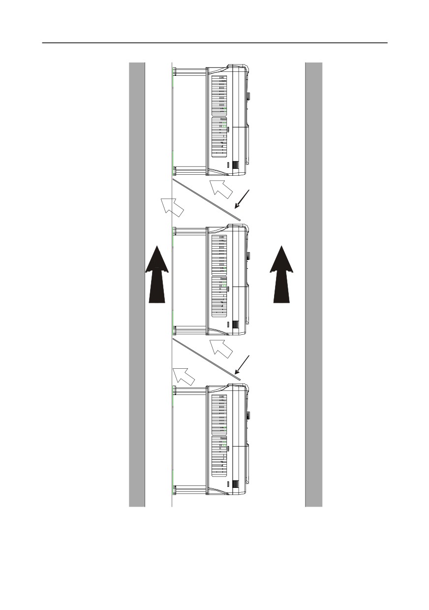
4.2.6 Vertical installation
Cold
Windshield
air
Hot
air
Cold
air
Windshield
Hot
air
Fig 4.5 Vertical installation
Note: During vertical installation, users must install windshield, otherwise, the inverter will experience
mutual interference, and the heat dissipation effect will be degraded.
-20-
Chapter 4
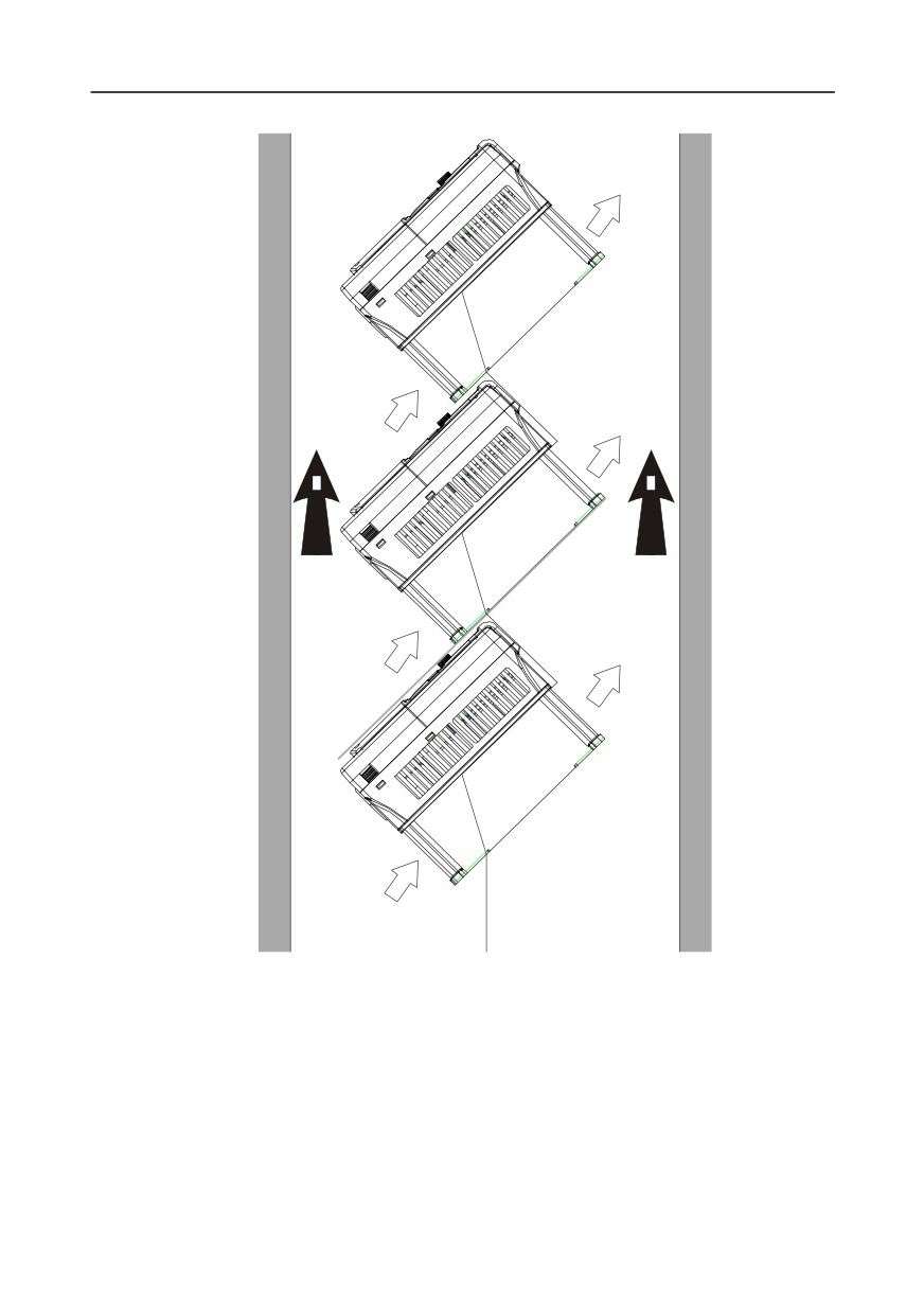
4.2.7 Tilted installation
Hot
air
Cold
air
Hot
air
Cold
air
Hot
air
Cold
air
Fig 4.6 Tilted installation
Note: During tilted installation, it is a must to ensure the air inlet duct and air outlet duct are separated
from each other to avoid mutual interference.
-21-
Chapter 4
4.3 Standard wiring of main circuit
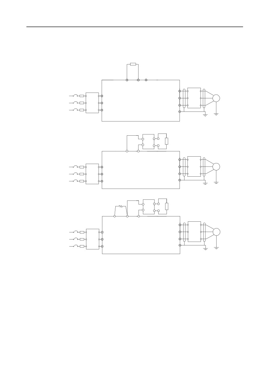
4.3.1 Wiring diagram of main circuit
4.3.1.1 AC 3PH 380V(-15%)-440V(+10%) main circuit wiring diagram
Brake resistor
(+)
PB (-)
U
Output
Input
R
reactor
3-phase
V
M
reactor
power
37kW and below
Output
S
380V±15%
Input
W
filter
50/60Hz
filter
T
Fuse
PE
Brake unit
DC+
Brake resistor
DC-
(+)
(-)
U
Output
reactor
3-phase
Input
R
V
M
reactor
45-110kW(inclusive)
Output
power
S
filter
380V±15%
W
Input
50/60Hz
filter
T
PE
Fuse
Brake unit
DC reactor
DC+
Brake resistor
DC-
P1
(+)
(-)
U
Output
V
reactor
Input
R
M
3-phase
Output
power
reactor
132kW and above
W
S
filter
380V±15%
Input
50/60Hz
filter
T
PE
Fuse
Fig 4.7 Main circuit wiring diagram for AC 3PH 380V(-15%)-440V(+10%)
Note:
1. The fuse, DC reactor, brake unit, brake resistor, input reactor, input filter, output reactor and
output filter are optional parts. See Appendix D Optional peripheral accessories for details.
2. P1 and (+) have been short connected by default for 380V 132kW and above inverters. If users
need to connect to external DC reactor, take off the short-contact tag of P1 and (+).
3. When connecting the brake resistor, take off the yellow warning sign marked with PB, (+) and (-)
on the terminal block before connecting the brake resistor wire, otherwise, poor contact may
occur.
4. Built-in brake unit is optional for 380V 45kW-110kW models.
-22-
Chapter 4
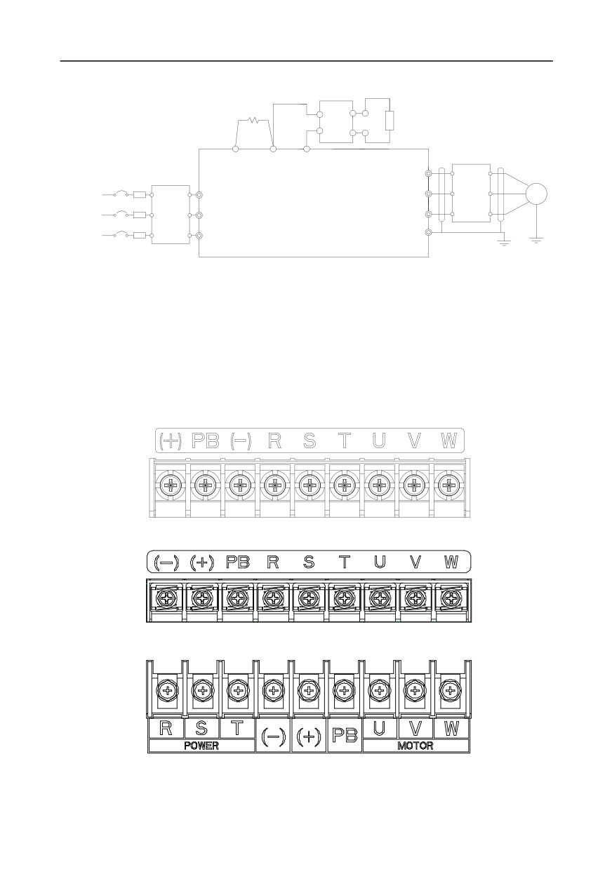
4.3.1.2 AC 3PH 520V(-15%)-690V(+10%) main circuit wiring diagram
Brake unit
DC reactor
DC+
Brake
resistor
DC-
P1
(+)
(-)
U
Output
reactor
Input
R
V
M
reactor
22kW and above
Output
3-phase power
filter
660V±15%
S
W
50/60Hz
Input filter
PE
T
Fuse
Fig 4.8 660V main circuit wiring diagram
Note:
1. The fuse, DC reactor, brake resistor, input reactor, input filter, output reactor and output filter are
optional parts. See Appendix D Optional peripheral accessories for details.
2. P1 and (+) have been short connected by default. If users need to connect to external DC reactor,
take off the short-contact tag of P1 and (+).
3. When connecting the brake resistor, take off the yellow warning sign marked with (+) and (-) on
the terminal block before connecting the brake resistor wire, otherwise, poor contact may occur.
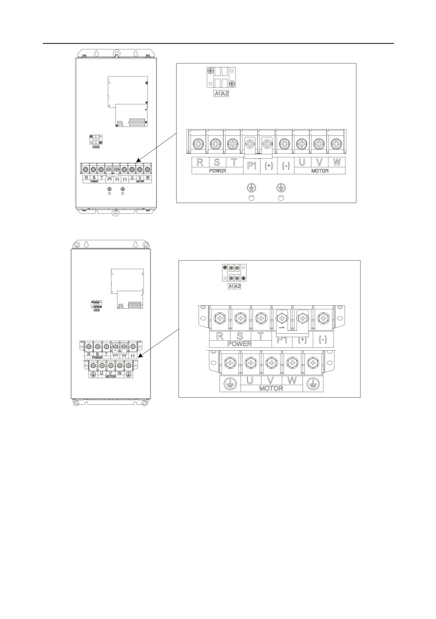
4.3.2 Main circuit terminal diagram
Fig 4.9 3PH 380V 22kW and below
Fig 4.10 3PH 380V 30-37kW
Fig 4.11 3PH 380V 45-110kW
-23-
Chapter 4
Fig 4.12 660V 22-45kW
Fig 4.13 660V 55-132kW
-24-
Chapter 4
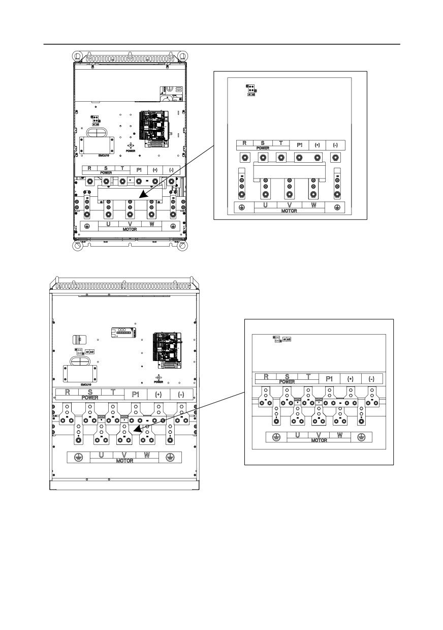
Fig 4.14 380V 132-200kW and 660V 160-220kW
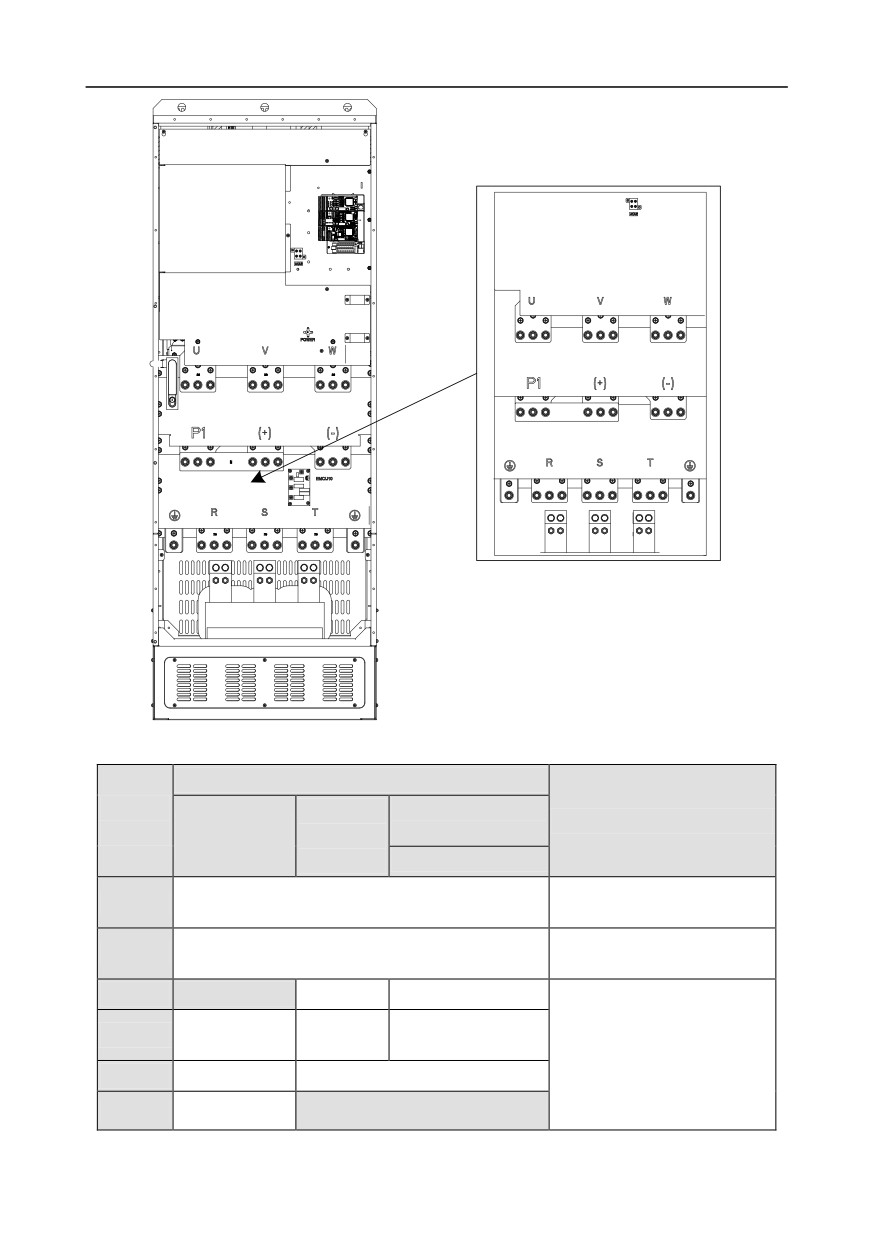
Fig 4.15 380V 220-315kW and 660V 250-355kW
-25-
Chapter 4
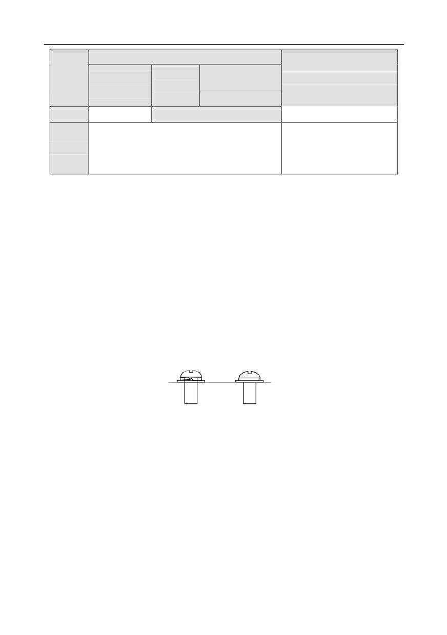
Fig 4.16 380V 355-500kW and 660V 400-630kW
Terminal name
Terminal
380V
380V 132kW and
380V 37kW and
Function description
sign
45-110kW
above
below
(inclusive)
660V
3PH AC input terminal, connect
R, S, T
Main circuit power input
to the grid
3PH AC output terminal,
U, V, W
Inverter output
connect to the motor
P1
Null
Null
DC reactor terminal 1
P1 and (+) connect to external
DC reactor terminal
Brake resistor
Brake unit
DC reactor terminal 2,
(+)
(+) and (-) connect to external
terminal 1
terminal 1
Brake unit terminal 1
brake unit terminal
(-)
/
Brake unit terminal 2
PB and (+) connect to external
PB
Brake resistor
Null
brake resistor terminal
-26-
Chapter 4
Terminal name
Terminal
380V
380V 132kW and
380V 37kW and
Function description
sign
45-110kW
above
below
(inclusive)
660V
terminal 2
Grounding terminal for safe
protection; each machine must
PE
Grounding resistor is less than 10 ohm
carry two PE terminals and
proper grounding is required
Note:
1. Do not use asymmetrical motor cable. If there is a symmetrical grounding conductor in the motor
cable besides the conductive shielded layer, ground the grounding conductor on the inverter end
and motor end.
2. Brake resistor, brake unit and DC reactor are optional parts.
3. Route the motor cable, input power cable and control cables separately.
4. "Null" means this terminal is not for external connection.
4.3.3 Wiring process of the main circuit terminals
1.
Connect the grounding line of the input power cable to the grounding terminal (PE) of the
inverter, and connect the 3PH input cable to R, S and T terminals and tighten up.
2.
Connect the grounding line of the motor cable to the grounding terminal of the inverter, and
connect 3PH motor cable to U, V and W terminals and tighten up.
3.
Connect the brake resistor which carries cables to the designated position.
4.
Fix all the cables outside the inverter mechanically if allowed.
NG
Y
The screw is
The screw is
not fastened
fastened
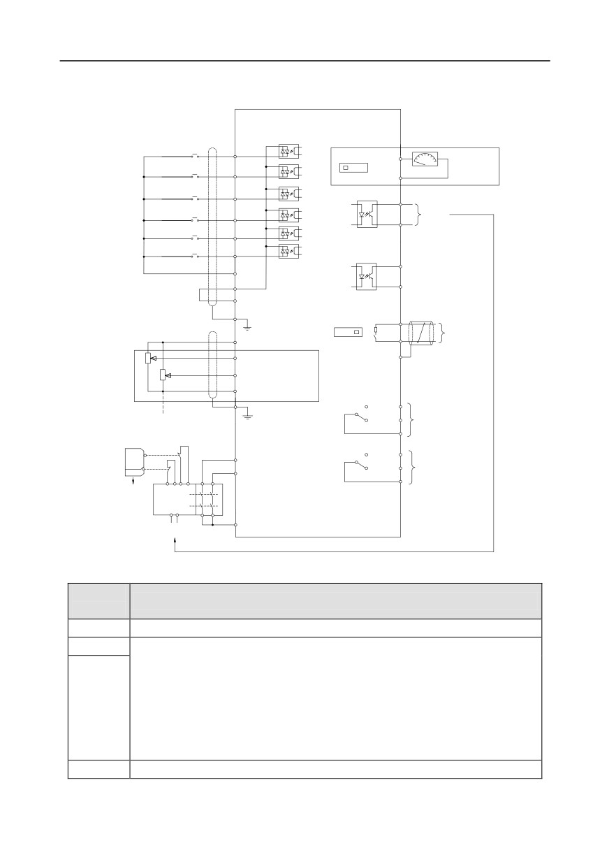
Fig 4.17 Screw installation diagram
-27-
Chapter 4
4.4 Standard wiring of control circuit
4.4.1 Wiring diagram of basic control circuit
Goodrive350 series
inverter
Forward running
S1
SW2
A01
Analog output
Jogging
S2
0-10V/0-20mA
V I
GND
Fault reset
S3
Y1
Y1
S4
CME
output
HDIA
HDIB
HDO
COM
Optional between high-
COM
speed pulse output and
PW
open collector output
+24V
PE
SW3
485+
RS485
power used for
485-
communication
+10Vfrequency setting
ON OFF
AI1
485G
multi-function
analog input
AI2
GND
RO1A
PE
-10V
RO1B
Relay 1
(external)
RO1C
output
Safety
switch
Safety
S2
RO2A
input
H1
Relay 2
RO2B
S1
H2
output
RO2C
Open circuit
Safety
controller
Safety state
+24V
feedback
Fig 4.18 Wiring diagram of control circuit
Terminal
Instruction
name
+10V
The inverter provides +10.5V power
AI1
1.
Input range: AI1 voltage/current can choose 0-10/ 0-20mA;
AI2: -10V-+10V voltage;
2.
Input impedance: 20kΩ during voltage input; 250Ω during current input;
3.
AI1 voltage or current input is set by P05.50;
AI2
4.
Resolution ratio: When 10V corresponds to 50Hz, the min. resolution ratio is
5mV;
5.
25°C, When input above 5V or 10mA, the error is ±0.5%
GND
+10.5V reference zero potential
-28-
Chapter 4
Terminal
Instruction
name
1.
Output range: 0-10V voltage or 0-20mA current
AO1
2.
Voltage or current output is set by toggle switch SW2;
3.
25°C, when input above 5V or 10mA, the error is ±0.5%.
RO1A
RO1 relay output; RO1A is NO, RO1B is NC, RO1C is common port
RO1B
Contact capacity: 3A/AC250V, 1A/DC30V
RO1C
RO2A
RO2 relay output; RO2A is NO, RO2B is NC, RO2C is common port
RO2B
Contact capacity: 3A/AC250V, 1A/DC30V
RO2C
1.
Switch capacity: 200mA/30V;
HDO
2.
Range of output frequency: 0-50kHz
3.
Duty ratio: 50%
COM
Common port of +24V
CME
Common port of open collector output; short connected to COM by default
1. Switch capacity: 200mA/30V;
Y1
2. Range of output frequency: 0-1kHz
485+
485 communication port,
485 differential signal port and standard
485
communication interface should use twisted shielded pair; the 120ohm terminal
485-
matching resistor of 485 communication is connected by toggle switch SW3.
PE
Grounding terminal
Provide input digital working power from external to internal;
PW
Voltage range: 12-24V
24V
The inverter provides user power; the max. output current is 200mA
COM
Common port of +24V
S1
Digital input 1
1.
Internal impedance: 3.3kΩ
S2
Digital input 2
2.
Accept 12-30V voltage input
S3
Digital input 3
3.
This terminal is bi-directional input terminal and supports
NPN/PNP connection modes
4.
Max. input frequency: 1kHz
S4
Digital input 4
5.
All are programmable digital input terminals, users can set the
terminal function via function codes
HDIA
Besides S1-S4 functions, it can also act as high frequency pulse input channel
Max. input frequency: 50kHz;
HDIB
Duty ratio: 30%-70%;
Supports quadrature encoder input; equipped with speed-measurement function
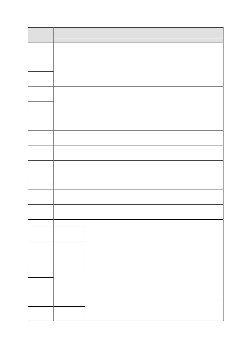
+24V—H1
STO input 1
1.
Safe torque off (STO) redundant input, connect to external NC
contact, STO acts when the contact opens, and the inverter
+24V—H2
STO input 2
stops output;
-29-
Chapter 4
Terminal
Instruction
name
2.
Safety input signal wires use shielded wire whose length is
within 25m;
3.
H1 and H2 terminals are short connected to +24V by default;
it is required to remove the short-contact tag on the terminal before
using STO function.
4.4.2 Input/output signal connection diagram
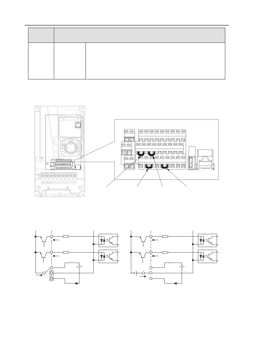
Set NPN /PNP mode and internal/external power via U-type short-contact tag. NPN internal mode is
adopted by default.
R01A
R02A
S1
S2
S3
S4 HDIA HDIB AI1 AI2 +10V
R01BR02B
H1 +24V+24VPW COM HDO Y1 AO1 GND
R01CR02C
PE H2 +24V COM COM CME 485+485-485G
U-type short-
U-type short-
U-type short-
U-type short-contact
contact tag of H1 contact tag of H2
contact tag of
tag of COM and
and +24V
and +24V
+24V and PW
+CME
Fig 4.19 Position of U-type short-contact tag
If input signal comes from NPN transistors, set the U-type short-contact tag between +24V and PW
based on the power used according to the figure below.
S1
S1
S2
S2
COM
COM
COM
COM
+ 24V
+ 24V
+24V
PW
PW
+ 24V
+ 24V
Internal power(NPN mode)
External power(NPN mode)
Fig 4.20 NPN mode
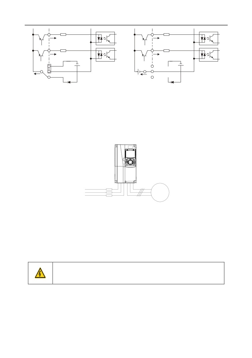
If input signal comes from PNP transistor, set the U-type short-contact tag based on the power used
according to the figure below.
-30-
Chapter 4
S1
S1
S2
S2
COM
COM
COM
COM
+ 24V
+ 24V
PW
PW
+ 24V
+ 24V
Internal power(PNP mode)
External power(PNP mode)
Fig 4.21 PNP mode
4.5 Wiring protection
4.5.1 Protect the inverter and input power cable in short-circuit
Protect the inverter and input power cable during short-circuit to avoid thermal overload.
Carry out protective measures according to the following requirements.
Inverter
Input cable
M3 ~
Fuse
Fig 4.22 Fuse configuration
Note: Select the fuse according to operation manual. During short-circuit, the fuse will protect
input power cables to avoid damage to the inverter; when internal short-circuit occurred to the
inverter, it can protect neighboring equipment from being damaged.
4.5.2 Protect the motor and motor cable in short circuit
If the motor cable is selected based on rated inverter current, the inverter will be able to protect the
motor cable and motor during short circuit without other protective devices.
If the inverter is connected to multiple motors, it is a must to use a separated
thermal overload switch or breaker to protect the cable and motor, which may
require the fuse to cut off the short circuit current.
4.5.3 Protect motor and prevent thermal overload
According to the requirements, the motor must be protected to prevent thermal overload. Once
overload is detected, users must cut off the current. The inverter is equipped with motor thermal
overload protection function, which will block output and cut off the current (if necessary) to protect
the motor.
-31-
Chapter 4
4.5.4 Bypass connection
In some critical occasions, industrial frequency conversion circuit is necessary to ensure proper
operation of the system when inverter fault occurs.
In some special cases, eg, only soft startup is needed, it will converts to power-frequency operation
directly after soft startup, corresponding bypass link is also needed.
Do not connect any power source to inverter output terminals U, V and W. The
voltage applied to motor cable may cause permanent damage to the inverter.
If frequent switch-over is needed, users can use the switch which carries mechanical interlock or a
contactor to ensure motor terminals will not be connected to input power cables and inverter output
ends simultaneously.
-32-
Chapter 5
Chapter 5 Basic operation instructions
5.1 What this chapter contains
This chapter tells users how to use the inverter keypad and the commissioning procedures for
common functions of the inverter.
5.2 Keypad introduction
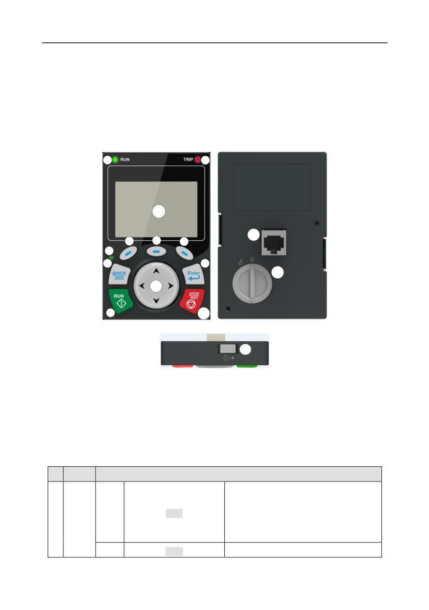
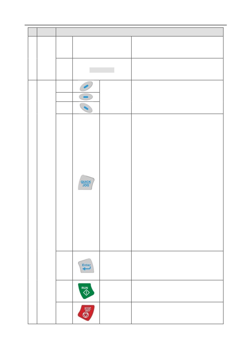
LCD keypad is included in the standard configuration of GD350 series inverter. Users can control the
inverter start/stop, read state data and set parameters via keypad.
1
2
12
13
4
5
6
3
7
8
14
11
9
10
15
Fig 5.1 Keypad diagram
Note:
1.
LCD keypad is armed with real-time clock, which can run properly after power off when installed
with batteries. The clock battery (type: CR2032) should be purchased by the user separately;
2.
LCD keypad support parameter-copy;
3.
When extending keypad lines to install the keypad, M3 screws can be used to fix the keypad
onto the door plate, or optional keypad installation bracket can be used for this purpose.
No.
Name
Instruction
Running indicator;
LED off - the inverter is stopped;
State
(1)
RUN
LED blinking - the inverter is in parameter
1
autotune
Indicator
LED on - the inverter is running
2)
TRIP
Fault indicator;
-33-
Chapter 5
No.
Name
Instruction
LED on - in fault state
LED off - in normal state
LED blinking - in pre-alarm state
Short-cut key indicator, which displays
(3)
QUICK/JOG
different state under different functions, see
definition of QUICK/JOG key for details
(4)
The function of function key varies with the
menu;
(5)
Function key
The function of function key is displayed in
(6)
the footer
Re-definable. It is defined as JOG function by
default, namely jogging. The function of
short-cut key can be set by the ones of
P07.12, as shown below.
0: No function ;
1: Jogging (linkage indicator (3); logic : NO);
2: Reserved;
3: FWD/REV switch-over (linkage indicator
(3); logic: NC) ;
(7)
Short-cut key
4: Clear UP/DOWN setting (linkage indicator
(3) logic: NC) ;
Button
5: Coast to stop (linkage indicator (3); logic:
2
NC) ;
area
6: Switching running command reference
mode in order (linkage indicator (3); logic:
NC) ;
7: Reserved;
Note: After restoring to default values, the
default function of short-cut key (7) is 1.
The function of confirmation key varies with
Confirmation
menus, eg confirming parameter setup,
(8)
key
confirming parameter selection, entering the
next menu, etc.
Under keypad operation mode, the running
(9)
Running key
key is used for running operation or
autotuning operation.
During running state, press the Stop/Reset
Stop/
(10)
key can stop running or autotuning; this key is
Reset key
limited by P07.04. During fault alarm state, all
-34-
//////////////////////////////////////////