Goodrive350 Series High-performance Multi-function Inver ter. Operation manual - page 2
Chapter 5
No.
Name
Instruction
the control modes can be reset by this key.
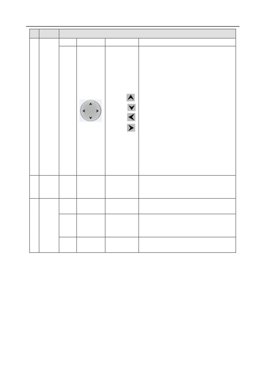
UP: The function of UP key varies with
interfaces, eg shifting up the displayed item,
shifting up the selected item, changing digits,
etc;
DOWN: The function of DOWN key varies
with interfaces, eg shifting down the
Direction key
displayed item, shifting down the selected
UP:
item, changing digits, etc;
(11)
DOWN:
LEFT: The function of LEFT key varies with
LEFT:
interfaces, eg switch over the monitoring
interface, eg shifting the cursor leftward,
RIGHT:
exiting current menu and returning to
previous menu, etc;
RIGHT: The function of RIGHT key varies
with interfaces, eg switch over the monitoring
interface, shifting the cursor rightward, enter
the next menu etc.
240×160 dot-matrix LCD; display three
Display
3
(12)
LCD
Display screen
monitoring parameters or six sub-menu items
area
simultaneously
RJ45
RJ45 interface is used to connect to the
(13)
RJ45 interface
interface
inverter.
Remove this cover when replacing or
Battery
Clock battery
4
Others
(14)
installing clock battery, and close the cover
cover
cover
after battery is installed
USB
mini USB
Mini USB terminal is used to connect to the
(15)
terminal
terminal
USB flash drive through an adapter.
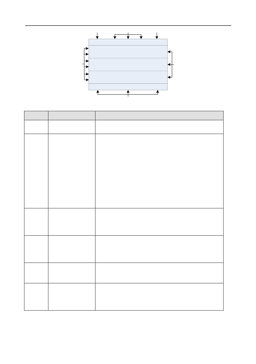
The LCD has different display areas, which displays different contents under different interfaces. The
figure below is the main interface of stop state.
-35-
Chapter 5
A
B
C
16:02:35
Forward Local Ready
01: GD350
Set frequency
P17.00 Hz
50.00
DC bus voltage
D
E
P17.11 V
540.0
Digital input terminal state
P17.12
0x0000
Monitoring
About
Menu
F
Fig 5.2 Main interface of LCD
Area
Name
Displayed contents
Real-time display
Display the real-time; clock battery is not included; the time
Header A
area
needs to be reset when powering on the inverter
Display the running state of the inverter:
1.
Display motor rotating direction: "Forward"
- Run
forward during operation; Reverse - Run reversely during
operation; "Forbid" - Reverse running is forbidden;
2.
Display inverter running command channel: "Local" -
Inverter running state
Header B
Keypad; "Terminal" - Terminal; "Remote" - Communication
display area
3.
Display current running state of the inverter : "Ready" -
The inverter is in stop state (no fault); "Run" - The inverter is
in running state; "Jog"
- The inverter is in jogging state;
"Pre-alarm" - the inverter is under pre-alarm state during
running; "Fault" - Inverter fault occurred.
1.
Display inverter station no.:
01-99, applied in
Inverter station no.
multi-drive applications (reserved function);
Header C
and model display
2.
Inverter model display: "GD350" - current inverter is
area
GD350 series inverter
The parameter name
Display the parameter name and corresponding function code
and function code
monitored by the inverter; three monitoring parameters can
Display D
monitored by the
be displayed simultaneously. The monitoring parameter list
inverter
can be edited by the user
Parameter value
Display the parameter value monitoring by the inverter, the
Display E
monitored by the
monitoring value will be refreshed in real time
inverter
Corresponding menu of function key (4), (5) and (6). The
Corresponding menu
corresponding menu of function key (4), (5) and (6) varies
Footer F
of function key (4),
with interfaces, and the contents displayed in this area is also
(5) and (6)
different
5.3 Keypad display
The display state of GD350 series keypad is divided into stop parameter display state, running
-36-
Chapter 5
parameter display stateand fault alarm display state.
5.3.1 Stop parameter display state
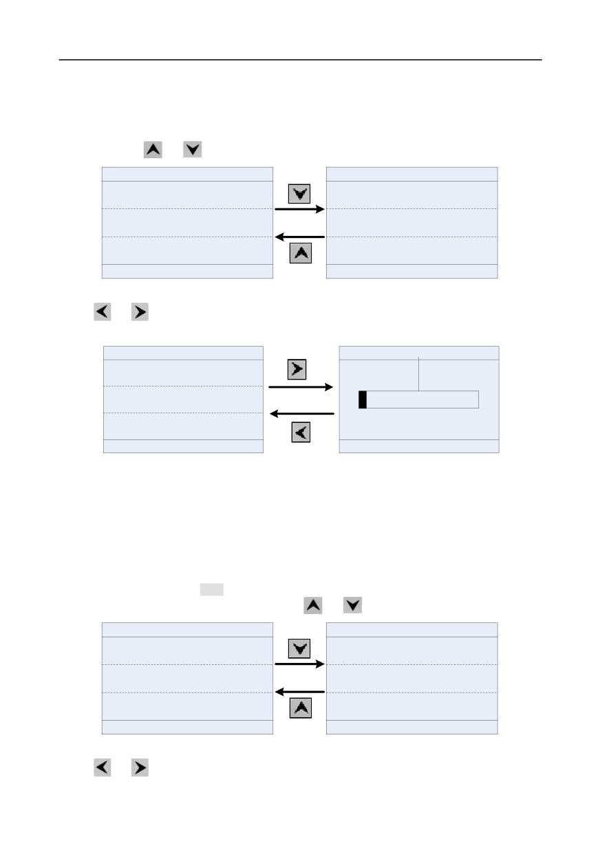
When the inverter is in stop state, the keypad displays stop state parameters, and this interface is the
main interface during power-up by default. Under stop state, parameters in various states can be
displayed. Press
or
to shift the displayed parameter up or down.
16:02:35
Forward Local Ready
01: GD350
16:02:35
Forward Local Ready
01: GD350
Set frequency
DC bus voltage
P17.00 Hz
50.00
P17.11 V
540.0
DC bus voltage
Digital input terminal state
P17.11 V
540.0
P17.12
0x0000
Digital input terminal state
Digital output terminal state
P17.12
0x0000
P17.13
0x0000
Monitoring
About
Menu
Monitoring
About
Menu
Fig 5.3 Stop parameter display state
Press
or
to switch between different display styles, including list display style and progress
bar display style.
16:02:35
Forward Local Ready
01: GD350
16:02:35
Forward Local Ready
01: GD350
Set frequency
Set frequency
50.00
50.00
P17.00 Hz
Hz
DC bus voltage
P17.11 V
540.0
0.00
630.00
Digital input terminal state
P17.12
0x0000
Monitoring
About
Menu
Return
Homepage
Fig 5.4 Stop parameter display state
The stop display parameter list is defined by the user, and each state variable function code can be
added to the stop display parameter list as needed. The state variable which has been added to the
stop display parameter list can also be deleted or shifted.
5.3.2 Running parameter display state
After receiving valid running command, the inverter will enter running state, and the keypad displays
running state parameter with RUN indicator on the keypad turning on. Under running state, multiple
kinds of state parameters can be displayed. Press
or
to shift up or down.
16:02:35
Forward Local Run
01: GD350
16:02:35
Forward Local
Run
01: GD350
Output frequency
Set frequency
P17.01 Hz
50.00
P17.00 Hz
50.00
Set frequency
DC bus voltage
P17.00 Hz
50.00
P17.11 V
540.0
DC bus voltage
Output voltage
540.0
378
P17.11 V
P17.03 V
Monitoring
About
Menu
Monitoring
About
Menu
Fig 5.5 Running parameter display state
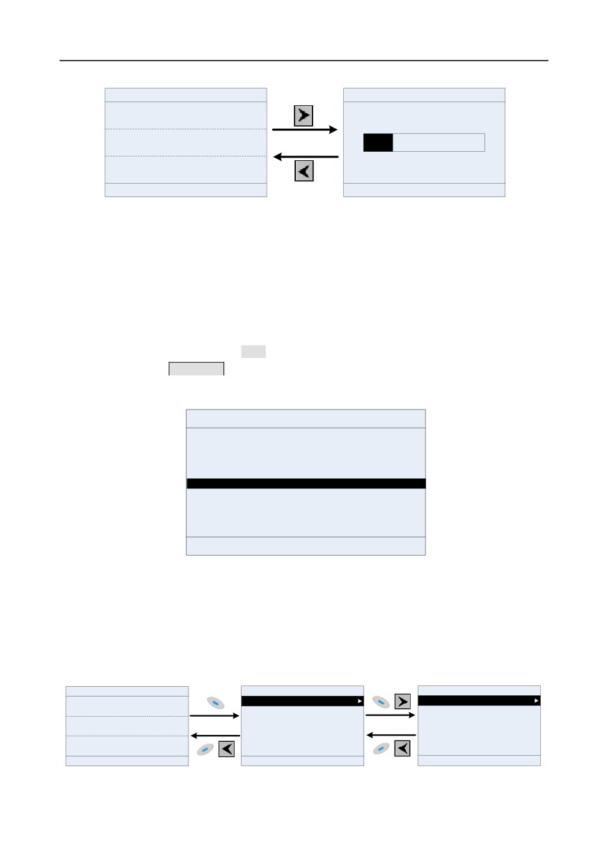
Press
or
to switch between different display styles, including list display style and progress
-37-
Chapter 5
bar display style.
16:02:35
Forward
Local Ready
01: GD350
16:02:35
Forward Local Ready
01: GD350
DC bus voltage
DC bus voltage
P17.11 V
540.00
540.00
V
Digital input terminal state
P17.12
0x0000
0.0
2000.0
Digital output terminal state
P17.13
0x0000
Monitoring
About
Menu
Return
Homepage
Fig 5.6 Running parameter display state
Under running state, multiple kinds of state parameters can be displayed. The running display
parameter list is defined by the user, and each state variable function code can be added to the
running display parameter list as needed. The state variable which has been added to the running
display parameter list can also be deleted or shifted.
5.3.3 Fault alarm display state
The inverter enters fault alarm display state once fault signal is detected, and the keypad displays
fault code and fault information with TRIP indicator on the keypad turning on. Fault reset operation
can be carried out via STOP/RSTkey, control terminal or communication command.
The fault code will be kept displaying until fault is removed.
16:02:35
Forward Local Fault
01: GD350
Type of present fault:
Fault code:
19
19:Current detection fault (ItE)
Return
Homepage
Confirm
Fig 5.7 Fault alarm display state
5.4 Keypad operation
Various operations can be performed on the inverter, including entering/exiting menu, parameter
selection, list modification and parameter addition.
5.4.1 Enter/exit menu
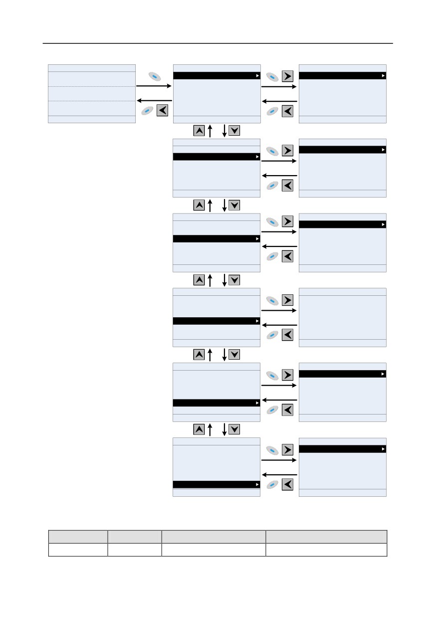
Regarding the monitoring menu, the operation relation between enter and exit is shown below.
16:02:35
Forward Local Ready
01: GD350
16:02:35
Forward Local Ready
01: GD350
16:02:35
Forward Local Ready
01: GD350
Set frequency
Standard monitoring setup
Stop state display parameter
P17.00 Hz
50.00
Running state display parameter
DC bus voltage
P17.11 V
540.0
Digital input terminal state
P17.12
0x0000
Monitoring
About
Menu
Return
Homepage
Select
Return
Homepage
Select
Fig 5.8 Enter/exit menu diagram 1
-38-
Chapter 5
Regarding the system menu, the operation relation between enter and exit is shown below.
16:02:35
Forward Local
Ready
01: GD350
16:02:35
Forward Local Ready
01: GD350
16:02:35
Forward Local Ready
01: GD350
Set frequency
Common parameter setup
P00.10:Keypad setting frequency
P17.00 Hz
50.00
Parameter setup
P00.00:Speed control mode
DC bus voltage
State monitoring/fault record
P00.11:Acceleration time 1
P17.11 V
540.0
Motor parameter autotuning
P00.12:Deceleration time 1
Digital input terminal state
Parameter backup/restore to default value
P00.01:Running command channel
P17.12
0x0000
System setting
P00.13:Running direction selection
Monitoring
About
Menu
Return
Homepage
Select
Return
Edit
Select
16:02:35
Forward Local Ready
01: GD350
16:02:35
Forward Local Ready
01: GD350
Common parameter setup
Quick setup for function code
Parameter setup
Basic parameter group setup
State monitoring/fault record
Motor parameter group setup
Motor parameter autotuning
Control parameter group setup
Parameter backup/restore to default value
Terminal function group setup
System setting
Optional card function group setup
Return
Homepage
Select
Return
Homepage
Select
16:02:35
Forward Local Ready
01: GD350
16:02:35
Forward Local Ready
01: GD350
Common parameter setup
State monitoring
Parameter setup
Fault record
State monitoring/fault record
Fault state
Motor parameter autotuning
Clear fault history
Parameter backup/restore to default value
Modified parameters
System setting
Return
Homepage
Select
Return
Homepage
Select
16:02:35
Forward Local Ready
01: GD350
16:02:35
Forward Local Ready
01: GD350
Common parameter setup
Parameter setup
Ensure the motor nameplate parameters are set
State monitoring/fault record
correctly!
Motor parameter autotuning
Parameter backup/restore to default value
System setting
Return
Homepage
Select
Return
Add
Select
16:02:35
Forward Local Ready
01: GD350
16:02:35
Forward Local Ready
01: GD350
Common parameter setup
Operate the storage area 1: BACKUP01
Parameter setup
Operate the storage area 2: BACKUP02
State monitoring/fault record
Operate the storage area 3: BACKUP03
Motor parameter autotuning
Restore function parameter to default value
Parameter backup/restore to default value
System setting
Return
Homepage
Select
Return
Edit
Select
16:02:35
Forward Local Ready
01: GD350
16:02:35
Forward Local Ready
01: GD350
Common parameter setup
Language selection
Parameter setup
Time/date
State monitoring
Backlight brightness adjustment
Fault record
Backlight time adjustment
Parameter backup/restore to default value
Power-on guiding enable
System setting
Power-on guiding settings
Return
Homepage
Select
Return
Homepage
Select
Fig 5.9 Enter/exit menu diagram 2
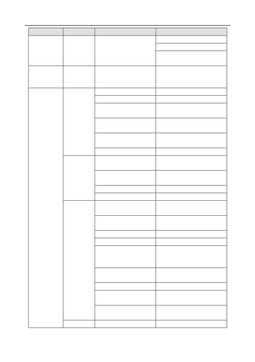
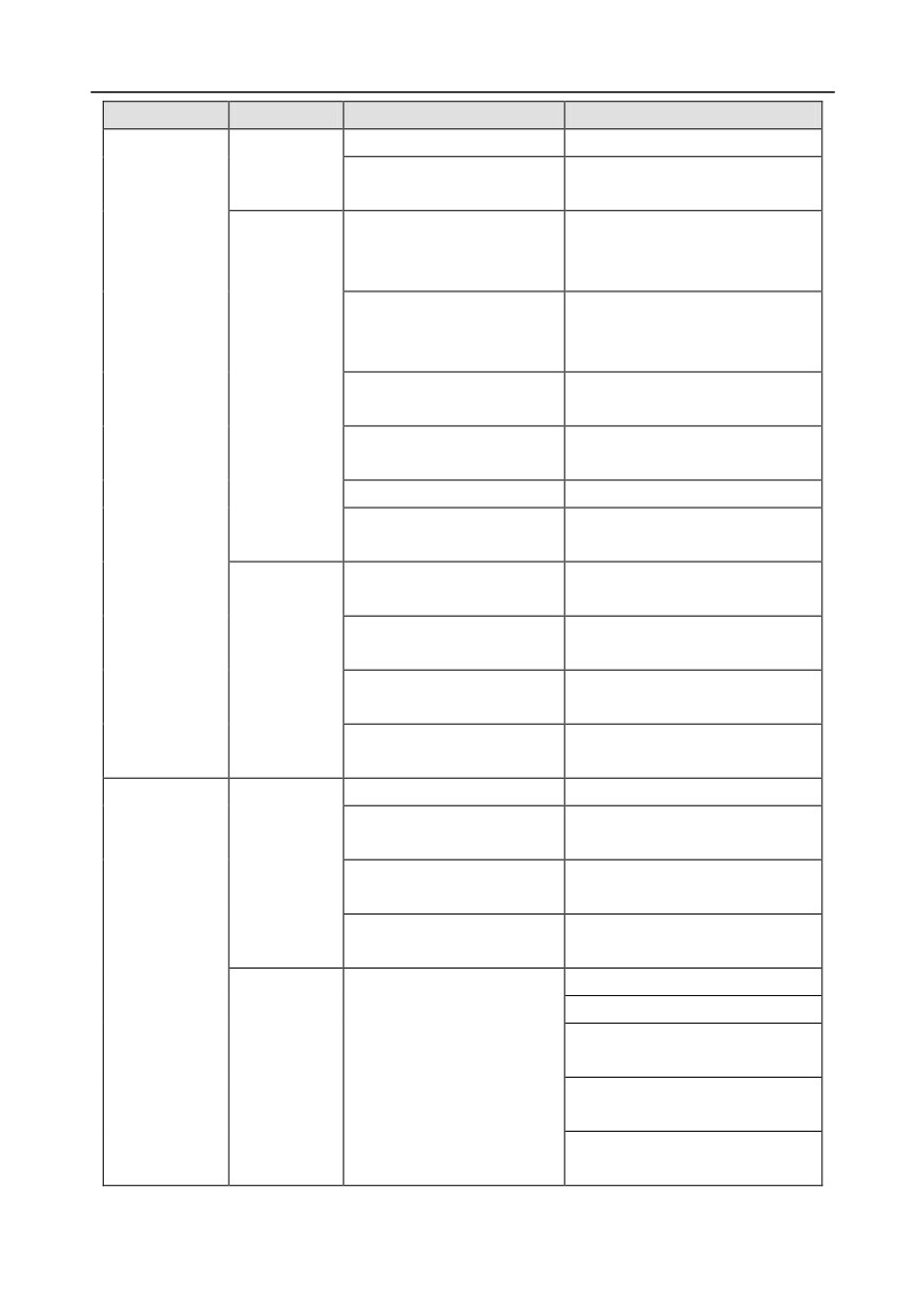
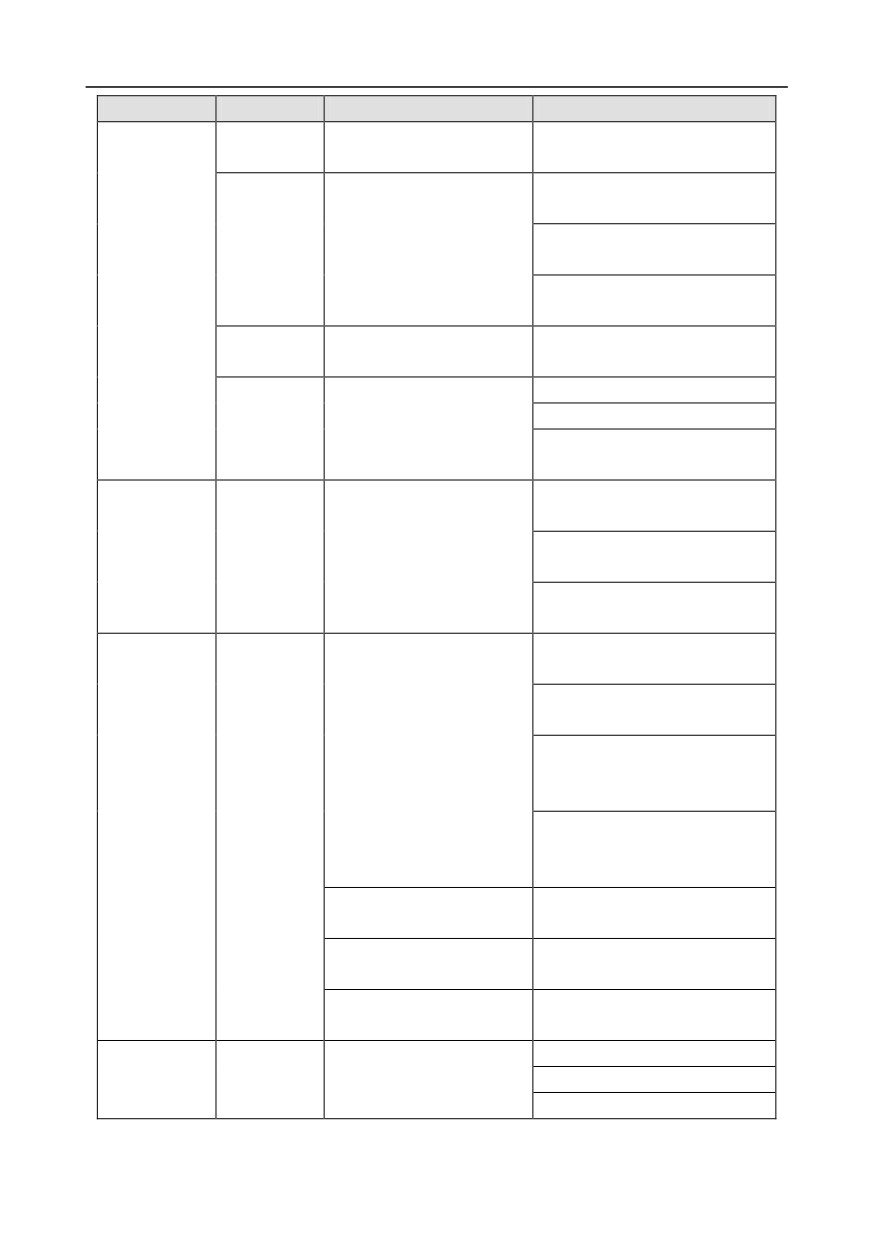
The keypad menu setup is shown as below.
First-level
Second-level
Third-level
Fourth-level
Common
/
/
P00.10: Set frequency via
-39-
Chapter 5
First-level
Second-level
Third-level
Fourth-level
parameter
keypad
setup
P00.00: Speed control mode
Pxx.xx
:
Common
parameter
setup xx
Quick setup
for function
/
Pxx.xx
code
P00: Basic function group
P00.xx
P07: HMI group
P07.xx
P08: Enhance function
P08.xx
Basic
group
parameter
P11: Protection parameter
P11.xx
group setup
group
P14: Serial communication
P14.xx
function group
P99: Factory function group
P99.xx
P02: Motor 1 parameter
P02.xx
group
Motor
P12: Motor 2 parameter
parameter
P12.xx
group
group setup
P20: Motor 1 encoder group
P20.xx
P24: Motor 2 encoder group
P24.xx
Parameter
P01: Start/stop control
P01.xx
setup
group
P03: Motor 1 vector control
P03.xx
group
P04: V/F control group
P04.xx
P09: PID control group
P09.xx
P10: Simple PLC and
Control
multi-step speed control
P10.xx
parameter
group
group setup
P13: Synchronous motor
P13.xx
control parameter group
P21: Position control group
P21.xx
P22: Spindle positioning
P22.xx
group
P23: Motor 2 vector control
P23.xx
group
Terminal
P05: Input terminal group
P05.xx
-40-
Chapter 5
First-level
Second-level
Third-level
Fourth-level
function
P06: Output terminal group
P06.xx
group setup
P98: AIAO calibration
P98.xx
function group
P15: Communication
extension card 1 function
P15.xx
group
P16: Communication
extension card 2 function
P16.xx
Optional card
group
function
P25: Extension I/O card
P25.xx
group setup
input function group
P26: Extension I/O card
P26.xx
output function group
P27: PLC function group
P27.xx
P28: Master/slave function
P28.xx
group
P90: Customized function
P90.xx
group 1
P91: Customized function
Default
P91.xx
group 2
function
P92: Customized function
group setup
P92.xx
group 3
P93: Customized function
P93.xx
group 4
P07: HMI group
P07.xx
P17: State-check function
P17.xx
group
State
P18: Closed-loop vector
monitoring
P18.xx
state check function group
P19: Extension card state
P19.xx
State
check function group
monitoring/fault
P07.27: Type of present fault
record
P07.28: Type of the last fault
P07.29: Type of the last but one
fault
Fault record
/
P07.30: Type of the last but two
fault
P07.31: Type of the last but three
fault
-41-
Chapter 5
First-level
Second-level
Third-level
Fourth-level
P07.32: Type of the last but four
fault
P07.33: Running frequency of
present fault
P07.34: Ramps frequency of
Fault state
/
present fault
P07.xx: xx state of the last but xx
fault
Clear fault
/
Ensure to clear fault history?
history
Pxx.xx has modified parameter 1
Modified
Pxx.xx has modified parameter 2
/
parameter
Pxx.xx has modified parameter
xx
Complete parameter rotary
autotuning
Motor
Complete parameter static
parameter
/
/
autotuning
autotuning
Partial
parameter
static
autotuning
Upload local function parameter
to keypad
Download complete keypad
function parameter
Operate the storage area 1:
Download
key
function
BACKUP01
parameters which are not in
motor group
Parameter
Download keypad function
backup/restore
/
parameters which are in motor
default value
group
Operate the storage area 2:
BACKUP012
Operate the storage area 3:
BACKUP03
Restore function parameter
Ensure to restore function
to default value
parameters to default value?
Language selection
System setup
/
/
Time/date
Backlight brightness regulation
-42-
Chapter 5
First-level
Second-level
Third-level
Fourth-level
Backlight time adjustment
Power-on guiding enable
Power-on guiding settings
Keyboard burning selection
Fault time enable
Control board burning selection
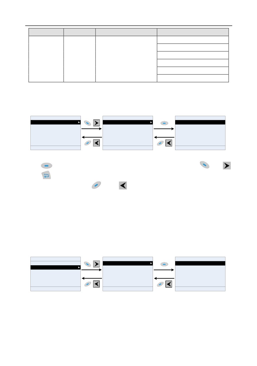
5.4.2 List edit
The monitoring items displayed in the parameter list of stop state can be added by users as needed
(through the menu of the function code in state check group), and the list can also be edited by users
eg "shift up", "shift down" and "delete from the list". The edit function is shown in the interface below.
16:02:35
Forward Local Ready
01: GD350
16:02:35
Forward Local Ready
01: GD350
16:02:35
Forward Local Ready
01: GD350
Parameter displayed in stop state
P17.00:Set frequency
Shift up
Parameter displayed in running state
P17.11:DC bus voltage
Shift down
P17.12:Digital input terminal state
Delete from the list
P17.13:Digital output terminal state
P17.23:PID reference value
P17.24:PID feedback value
Return
Homepage
Select
Return
Edit
Confirm
Return
Homepage
Select
Fig 5.10 List edit diagram 1
Press
key to enter edit interface, select the operation needed, and press
key,
key or
key to confirm the edit operation and return to the previous menu (parameter list), the
returned list is the list edited. If
key or
key is pressed in edit interface wihouth selecting
edit operation, it will return to the previous menu (parameter list remain unchanged).
Note: For the parameter objects in the list header, shift-up operation will be invalid, and the
same principle can be applied to the parameter objects in the list footer; after deleting a
certain parameter, the parameter objects under it will be shifted up automatically.
The monitoring items displayed in the parameter list of running state can be added by users as
needed (through the menu of the function code in state check group), and the list can also be edited
by users eg "shift up", "shift down" and "delete from the list". The edit function is shown in the
interface below.
16:02:35
Forward Local Ready
01: GD350
16:02:35
Forward Local Ready
01: GD350
16:02:35
Forward Local Ready
01: GD350
Parameter displayed in stop state
P17.01:Output frequency
Shift up
Parameter displayed in running state
P17.00:Set frequency
Shift down
P17.11:DC bus voltage
Delete from the list
P17.03:Output voltage
P17.04:Output current
P17.05:Motor speed
Return
Homepage
Select
Return
Edit
Confirm
Return
Homepage
Select
Fig 5.11 List edit diagram 2
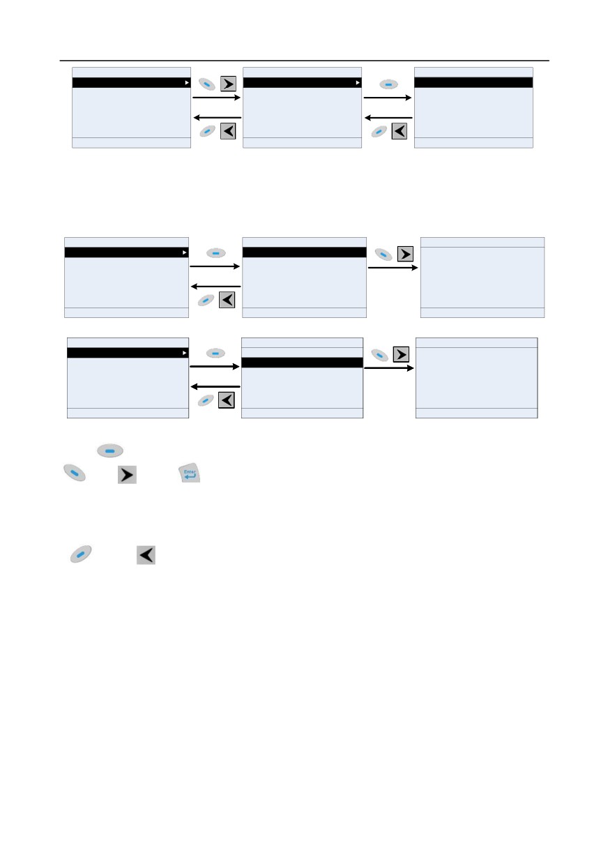
The parameter list of common parameter setup can be added, deleted or adjusted by users as
needed, including delete, shift-up and shift-down; the addition function can be set in a certain function
code of a function group. The edit function is shown in the figure below.
-43-
Chapter 5
16:02:35
Forward
Local Ready
01: GD350
16:02:35
Forward
Local Ready
01: GD350
16:02:35
Forward Local
Ready
01: GD350
Common parameter
P00.10:Keypad setting frequency
Shift up
setup
Parameter setup
P00.00:Speed control mode
Shift down
State monitoring/fault
P00.11:Acceleration time 1
Delete from the list
record
Motor parameter
P00.12:Deceleration time 1
autotuning
Parameter backup/restore
P00.01:Running command channel
to default value
System setting
P00.13:Running direction selection
Return
Homepage
Select
Return
Edit
Select
Return
Homepage
Select
Fig 5.12 List edit diagram 3
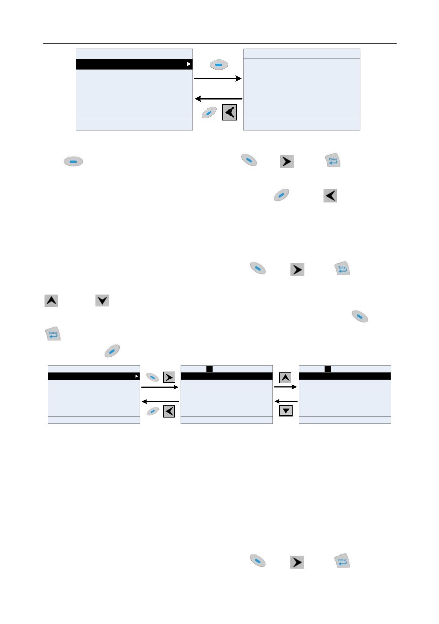
5.4.3 Add parameters to the parameter list displayed in stop/running state
In the fourth-level menu of "State monitoring", the parameters in the list can be added to the
"parameter displayed in stop state" list or "parameter displayed in running state" list as shown below.
16:02:35
Forward
Local
Ready
01: GD350
16:02:35
Forward
Local
Ready
01: GD350
16:02:35
Forward
Local
Ready
01: GD350
P17.00:Setting frequency
Add to the parameter list displayed in stop state
P17.01:Output frequency
Add to the parameter list displayed in running state
Ensure to add to the parameter list
P17.02:Ramps reference frequency
displayed in stop state?
P17.03:Output voltage
P17.04:Output current
P17.05:Motor speed
Return
Add
Select
Return
Homepage
Confirm
Return
Homepage
Confirm
16:02:35
Forward
Local Ready
01: GD350
16:02:35
Forward
Local Ready
01: GD350
16:02:35
Forward
Local Ready
01: GD350
P17.00:Setting frequency
Add to the parameter list displayed in stop state
P17.01:Output frequency
Add to the parameter list displayed in running state
Ensure to add to the parameter list
P17.02:Ramps reference frequency
displayed in running state?
P17.03:Output voltage
P17.04:Output current
P17.05:Motor speed
Return
Add
Select
Return
Homepage
Confirm
Return
Homepage
Confirm
Fig 5.13 Add parameter diagram 1
Press
key to enter parameter addition interface, select the operation needed, and press
key,
key or
key to confirm the addition operation. If this parameter is not included in
the "parameter displayed in stop state" list or "parameter displayed in running state" list, the
parameter added will be at the end of the list; if the parameter is already in the "parameter displayed
in stop state" list or "parameter displayed in running state" list, the addition operation will be invalid. If
key or
key is pressed without selecting addition peration in "Addition" interface, it will
return to monitoring parameter list menu.
Part of the monitoring parameters in P07 HMI group can be added to the "parameter displayed in stop
state" list or "parameter displayed in running state" list; All the parameters in P17, P18 and P19 group
can be added to the "parameter displayed in stop state" list or "parameter displayed in running state"
list.
Up to 16 monitoring parameters can be added to the "parameter displayed in stop state" list; and up
to 32 monitoring parameters can be added to the "parameter displayed in running state" list.
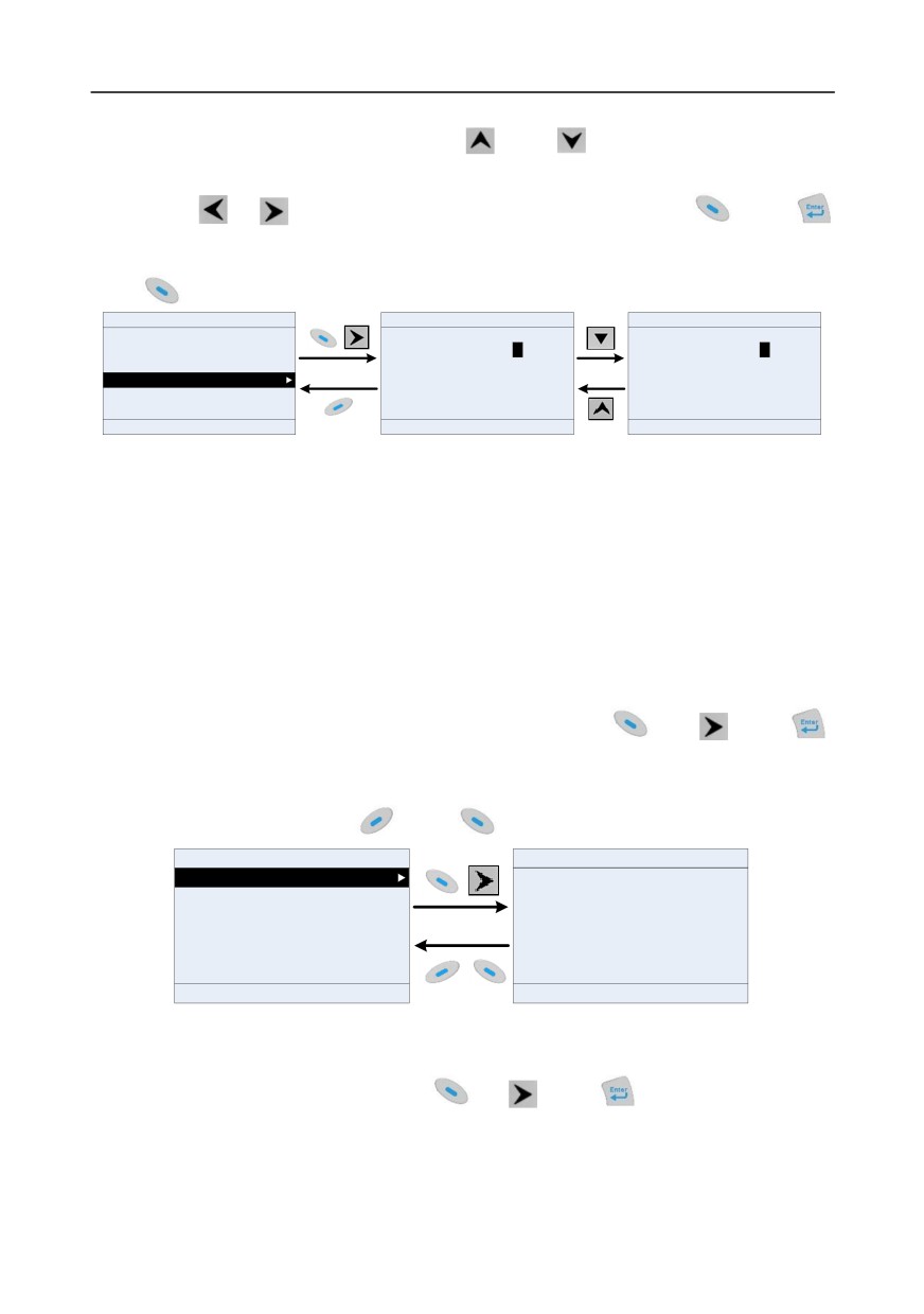
5.4.4 Add parameter to common parameter setup list
In fourth-level menu of "parameter setup" menu, the parameter in the list can be added to the
"common parameter setup" list as shown below.
-44-
Chapter 5
16:02:35
Forward Local Ready
01:GD350
16:02:35
Forward Local Ready
01:GD350
P01.00:Running mode of start
P01.01:Starting frequency of direct start
Ensure to add to common
P01.02:Hold-up time of starting frequency
parameter setup?
P01.03:Brake current before start
P01.04:Brake time before start
P01.05:Acceleration/deceleration mode selection
Return
Add
Select
Return
Homepage
Confirm
Fig 5.14 Add parameter diagram 2
Add
key to enter addition interface, and press
key,
key or
key to confirm
the addition operation. If this parameter is not included in the original "common parameter setup" list,
the newly-added parameter will be at the end of the list; if this parameter is already in the "common
parameter setup" list, the addition operation will be invalid. If
key or
key is pressed
without selecting addition operation, it will return to parameter setup list menu.
All the function code groups under parameter setup sub-menu can be added to "common parameter
setup" list. Up to 64 function codes can be added to the "common parameter setup" list.
5.4.5 Parameter selection edit interface
In the fourth-level menu of "parameter setup" menu, press
key,
key or
key to enter
parameter selection edit interface. After entering edit interface, current value will be highlighted. Press
key and
key to edit current parameter value, and the corresponding parameter item of
current value will be highlighted automatically. After parameter selection is done, press
key or
key to save the selected parameter and return to the previous menu. In parameter selection edit
interface, press
key to maintain the parameter value and return to the previous menu.
16:02:35
Forward
Local
Ready
01:GD350
Current value:0
Default value:2
Authority:√
Current value:1
Default value:2
Authority:√
P00.00:Speed control mode
0:SVC 0
1:SVC 1
P00.01:Running command channel
1:SVC 1
2:V/F mode
P00.02:Communication command channel
2:V/F mode
3:VC mode
P00.03:Max. output frequency
3:VC mode
P00.04:Upper limit of running frequency
P00.05:Lower limit of running frequency
Return
Add
Select
Return
Homepage
Confirm
Return
Homepage
Confirm
Fig 5.15 Parameter selection edit interface
In parameter selection edit interface, the "authority" on the top right indicates whether this parameter
is editable or not.
"√" indicates the set value of this parameter can be modified under current state.
"×" indicates the set value of this parameter cannot be modified under current state.
"Current value" indicates the value of current option.
"Default value" indicates the default value of this parameter.
5.4.6 Parameter setup edit interface
In the fourth-level menu in "parameter setup" menu, press
key,
key or
key to enter
-45-
Chapter 5
parameter setup edit interface. After entering edit interface, set the parameter from low bit to high bit,
and the bit under setting will be highlighted. Press
key or
key to increase or decrease the
parameter value (this operation is valid until the parameter value exceeds the max. value or min.
value); press
or
to shift the edit bit. After parameters are set, press
key or
key
to save the set parameters and return to the previous parameter. In parameter setup edit interface,
press
to maintain the original parameter value and return to the previous menu.
16:02:35
Forward Local Ready
01: GD350
Current value:50.00
Authority: √
Current value:50.00
Authority: √
P00.00: Speed control mode
Max. output frequency
Hz
Max. output frequency
Hz
P00.01: Running command channel
050.00
050.01
P00.02: Communication command channel
Max. value: 630.00
Max. value: 630.00
P00.03: Max. output frequency
Min. value: 50.00
Min. value: 50.00
P00.04: Upper limit of running frequency
Default value: 50.00
Default value: 50.00
P00.05: Lower limit of running frequency
Return
Add
Select
Return
Homepage
Confirm
Return
Homepage
Confirm
Fig 5.16 Parameter setup edit interface
In parameter selection edit interface, the "authority" on the top right indicates whether this parameter
can be modified or not.
"√" indicates the set value of this parameter can be modified under current state.
"×" indicates the set value of this parameter cannot be modified under current state.
"Current value" indicates the value saved last time.
"Default value" indicates the default value of this parameter.
5.4.7 State monitoring interface
In the fourth-level menu of "state monitoring/fault record" menu, press
key,
key or
key to enter state monitoring interface. After entering state monitoring interface, the current parameter
value will be displayed in real time, this value is the actually detected value which cannot be modified.
In state monitoring interface, press
key or
key to return to the previous menu.
16:02:35
Forward Local Ready
01: GD350
16:02:35
Forward
Local Ready
01: GD350
P17.00:Set frequency
Setting frequency
Hz
P17.01: Output frequency
50.00
P17.02: Ramps reference frequency
Max. value: 630.00
P17.03: Output voltage
Min. value: 0.0
P17.04: Output current
Default value: 0.0
P17.05: Motor speed
Return
Add
Select
Return
Homepage
Confirm
Fig 5.17 State monitoring interface
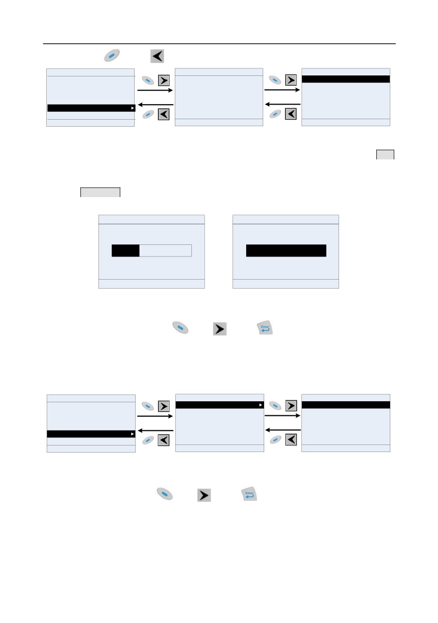
5.4.8 Motor parameter autotuning
In "Motor parameter autotuning" menu, press
key,
key or
key to enter motor
parameter autotuning selection interface, however, before entering motor parameter autotuning
interface, users must set the motor nameplate parameters correctly. After entering the interface,
select motor autotuning type to carry out motor parameter autotuning. In motor parameter autotuning
-46-
Chapter 5
interface, press
key or
key to return to the previous menu.
16:02:35
Forward Local Ready
16:02:35
Forward Local Ready
01: GD350
16:02:35
Forward
Local
Ready
01: GD350
Common parameter setup
Complete parameter rotary autotuning
Parameter setup
Complete parameter static autotuning
Ensure motor nameplate parameters are set
State monitoring/fault record
correctly!
Partial parameter static autotuning
Motor parameter autotuning
Parameter backup/restore to default value
System setting
Return
Homepage
Select
Return
Add
Confirm
Return
Homepage
Confirm
Fig 5.18 Parameter autotuning operation diagram
After selecting motor autotuning type, enter motor parameter autotuning interface, and press RUN
key to start motor parameter autotuning. After autotuning is done, a prompt will pop out indicating
autotuning is succeeded, and then it will return to the main interface of stop. During autotuning, users
can press STOP/RST key to terminate autotuning; if any fault occur during autotuning, the keypad will
pop out a fault interface.
16:02:35
Forward Local Run
01: GD350
16:02:35
Forward Local Run
01: GD350
Autotuning step:1
Autotuning step:3
In parameter autotuning
In parameter autotuning
Return
Homepage
Stop
Return
Homepage
Stop
Fig 5.19 Parameter autotuning finished
5.4.9 Parameter backup
In "parameter backup" menu, press
key,
key or
key to enter function parameter
backup setting interface and function parameter restoration setup interface to upload/download
inverter parameters, or restore inverter parameters to default value. The keypad has three different
storage areas for parameter backup, and each storage area can save the parameters of one inverter,
namely it can save parameters of three inverter in total.
16:02:35
Forward Local Ready
16:02:35
Forward Local Ready
16:02:35
Forward Local Ready
01: GD350
Common parameter setup
Operate the storage area 1: BACKUP01
Upload local function parameters to keypad
Parameter setup
Operate the storage area 2: BACKUP02
Download complete keypad function parameters
State monitoring/fault record
Operate the storage area 3: BACKUP03
Download keypad function parameters not in motor
group
Motor parameter autotuning
Restore function parameter to default value
Download keypad function parameters in motor group
Parameter backup/restore to default value
System setting
Return
Homepage
Select
Return
Edit
Select
Return
Homepage
Select
Fig 5.20 Parameter backup operation diagram
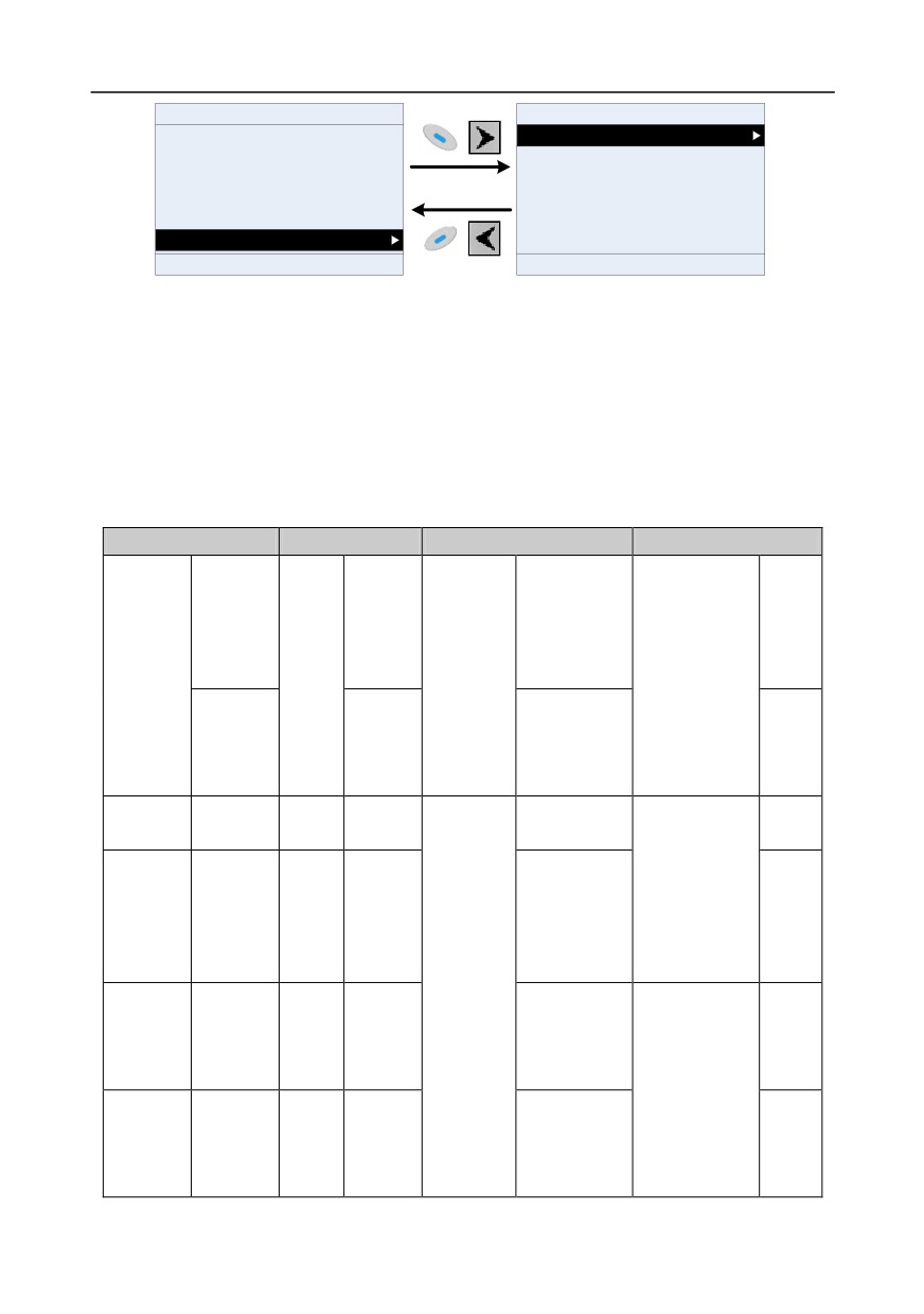
5.4.10 System setup
In "System setup" menu, press
key,
key or
key to enter system setup interface to
set keypad language, time/date, backlight brightness, backlight time and restore parameters.
Note: Clock battery is not included, and the keypad time/date needs to be reset after power off. If
time-keeping after power off is needed, users should purchase the clock batteries separately.
-47-
Chapter 5
16:02:35
Forward Local Ready
16:02:35
Forward Local Ready
Common parameter setup
Language selection
Parameter setup
Time/date
State monitoring
Backlight brightness adjustment
Fault record
Backlight time adjustment
Parameter backup/restore to default value
Power-on guiding enable
System setting
Power-on guiding settings
Return
Homepage
Select
Return
Homepage
Select
Fig 5.21 System setup diagram
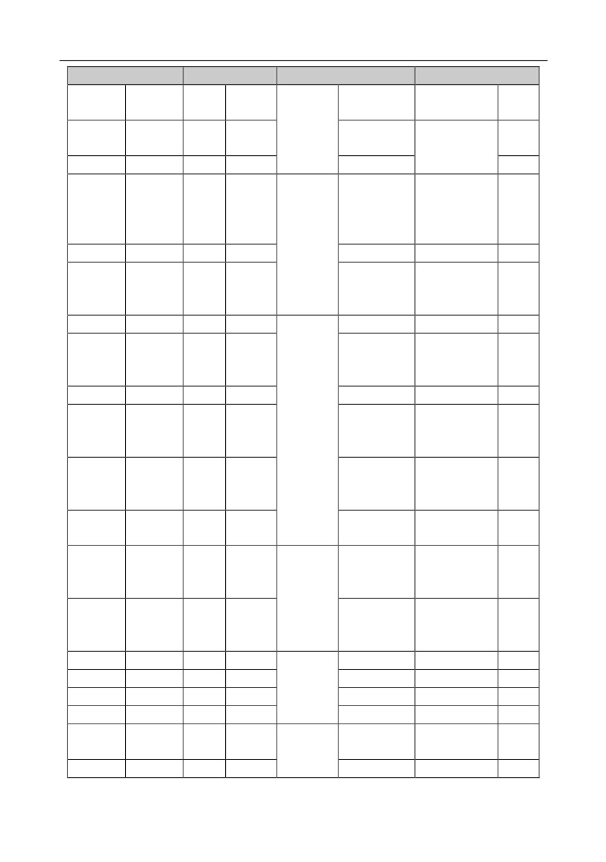
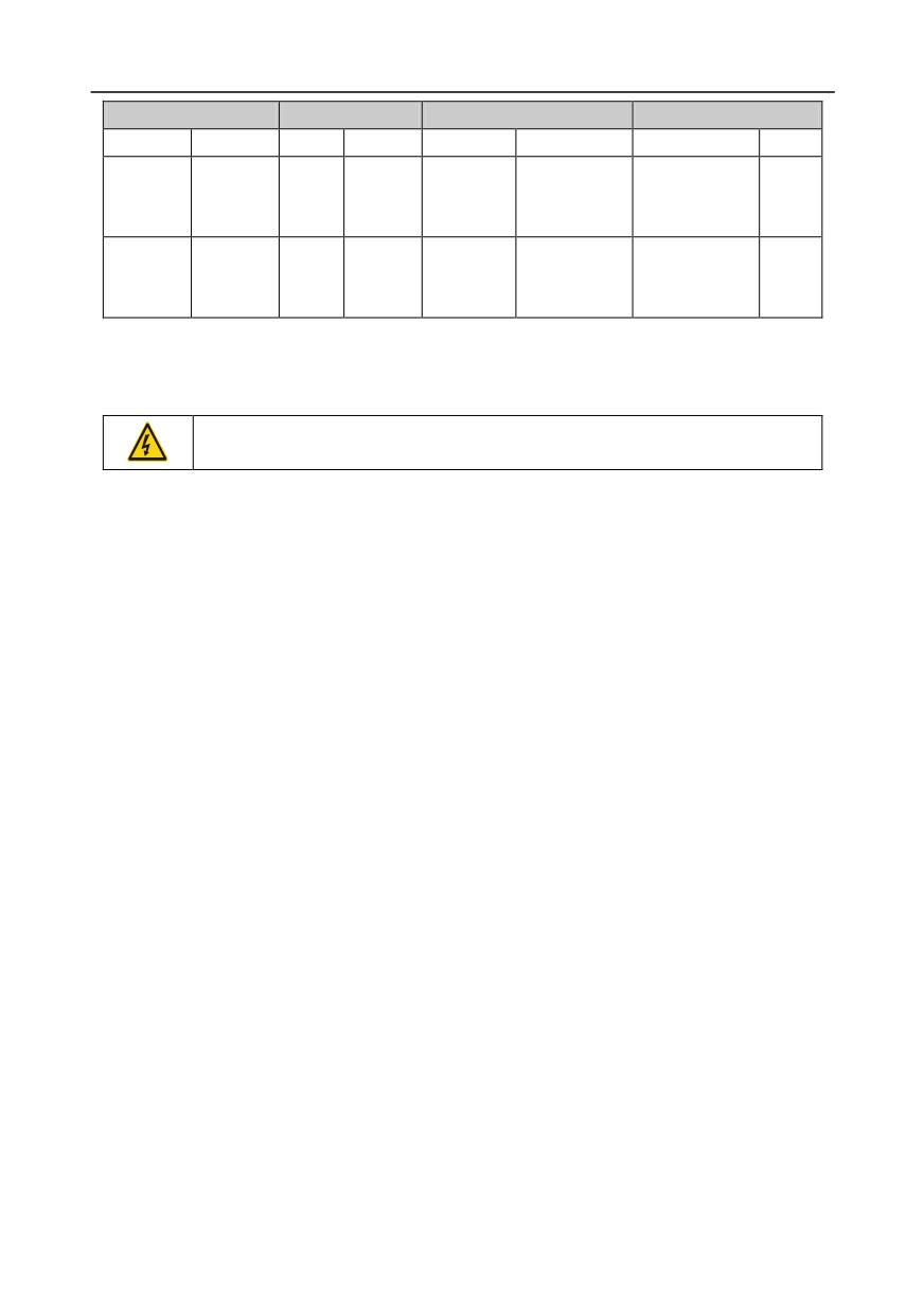
5.4.11 Power-on guiding settings
The keyboard supports the power-on guiding function, mainly for the first power-on situation, guiding
the user to enter the setting menu, and gradually implementing basic functions such as basic
parameter setting, direction judgment, mode setting and autotuning. The power-on guiding enable
menu guides the user to enable power-on to boot each time. Power-on guiding setup menu guides
the user to set step by step according to the functions.
The power-on guide is shown as below.
First-level
Second-level
Third-level
Fourth-level
0:
0:
Powe-
Simplified
Power-
on
Whether to
0:Yes
Yes
Whether to test
Chinese
on
each
enter the
the motor
Language
guiding
time
power-on
rotation
enable
1:
guiding
direction?
Power
settings?
1: English
1:No
No
on only
once
0: Set via
Press the JOG
Yes
keypad
button first. It is
currently
forward, Is it
P00.06
1: Set via AI1
consistent with
No
A frequency
the
command
expectations?
selection
0:
A frequency
Asynch
2: Set via AI2
command
ronous
selection
P02.00 Type of
motor
motor 1
1:
Synchr
3: Set via AI3
onous
motor
-48-

Chapter 5
First-level
Second-level
Third-level
Fourth-level
P02.01 Rated
4: Set via
power of
high-speed
asynchronous
pulse HDIA
motor 1
P02.02 Rated
5: Set via
frequency of
simple PLC
asynchronous
program
motor 1
P02.03 Rated
6: Set via
speed of
multi-step
asynchronous
speed running
motor 1
P02.04 Rated
7: Set via PID
voltage of
control
asynchronous
motor 1
8: Set via
P02.05 Rated
MODBUS
current of
communicatio
asynchronous
n
motor 1
9: Set via
PROFIBUS/C
P02.15 Rated
ANopen/Devic
power of
eNET
synchronous
communicatio
motor 1
n
10: Set via
P02.16 Rated
Ethernet
frequency of
communicatio
synchronous
n
motor 1
P02.17 Number
11: Set via
of pole pairs of
high-speed
synchronous
pulse HDIB
motor 1
P02.18 Rated
12: Set via
voltage of
pulse string AB synchronous
motor 1
13: Set via
P02.19 Rated
EtherCat/Profi
current of
-49-
Chapter 5
First-level
Second-level
Third-level
Fourth-level
netcommunica
synchronous
tion
motor 1
14: Set via
Whether to
Yes
PLC card
conduct
15: Reserved
autotuning?
No
Motor
parameter
0: Keypad
P00.01
autotuning
Running
interface
command
1: Terminal
channel
2:
Communicatio
n
0: MODBUS
P00.02
1: PROFIBUS/
Communic
CANopen/Devi
ation
cenet
running
2: Ethernet
command
3:
channel
EtherCat/Profi
Communic
net
ation
4: PLC
running
programmable
command
card
channel
5: Bluetooth
card
0: Disable
P08.37
energy-consu
Enable/disa
mption
ble energy-
1: Enable
consumptio
energy-consu
n brake
mption
P00.00
0: SVC 0
Speed
1: SVC 1
control
2: VF control
mode
3: VC
0: Decelerate
P01.08
to stop
Stop mode
1: Coast to
-50-
Chapter 5
First-level
Second-level
Third-level
Fourth-level
stop
P00.11
Acceleratio
n time
P00.12
Deceleratio
n time
5.5 Basic operation instruction
5.5.1 What this section contains
This section introduces the function modules inside the inverter
Ensure all the terminals are fixed and tightened firmly.
Ensure the motor matches with the inverter power.
5.5.2 Common commissioning procedures
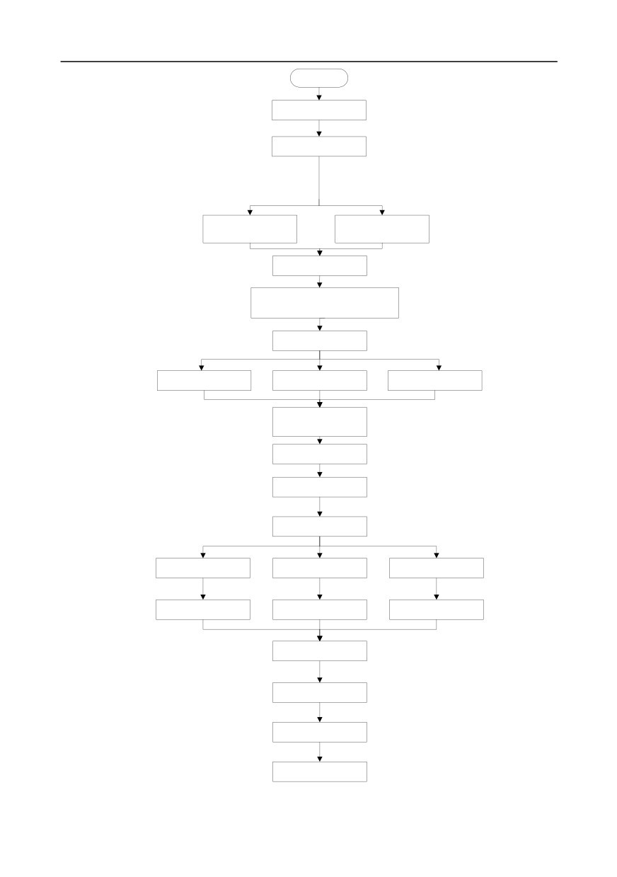
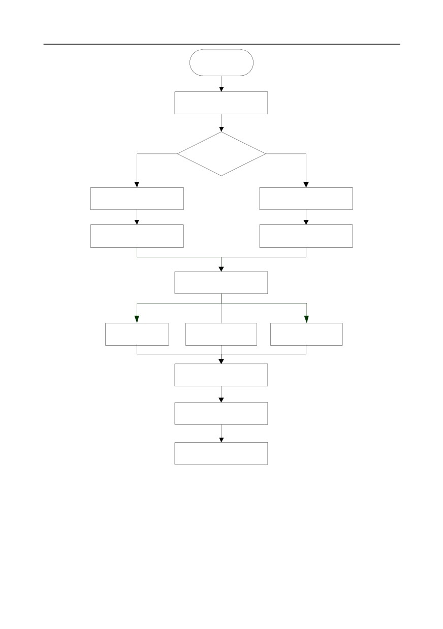
The common operation procedures are shown below (take motor 1 as an example).
-51-
Chapter 5
Start
Power up after confirming the
wiring is correct
Restore to default value
(P00.18=1)
Set the motor parameters of
Set the motor parameters of
P02.01-P02.05 as per the
P02.15-P02.19 as per the
motor nameplate
motor nameplate
Press QUICK/JOG to jog
If the motor rotates in wrong direction, power off
and exchange the motor wires of any two phases,
and power on again
Set autotuning mode
(P00.15)
Complete parameter rotary
Complete parameter static
Partial parameter rotary
autotuning
autotuning
autotuning
Start autotuning after pressing
RUN key, and stop after
autotuning is done
Set running command channel
(P00.01, P00.02)
Set running frequency
Set speed running control
mode (P00.00)
SVPWM control mode
SVC 1 (P00.00=0)
SVC 2 (P00.00=1)
(P00.00=2)
Set vector control parameters
Set vector control parameters
Set V/F parameters in P04
in P03 group
in P03 group
group
Set start/stop control
parameters in P01 group
Run after running command
Stop after stop command
End
Note: If fault occurred, rule out the fault cause according to "fault tracking".
-52-

Chapter 5
The running command channel can be set by terminal commands besides P00.01 and P00.02.
Multi-function terminal
Multi-function terminal
Multi-function terminal
Current running
function (36)
function (37)
function (38)
command channel
Command switches to
Command switches to
Command switches to
P00.01
keypad
terminal
communication
Keypad
/
Terminal
Communication
Terminal
Keypad
/
Communication
Communication
Keypad
Terminal
/
Note: "/" means this multi-function terminal is valid under current reference channel.
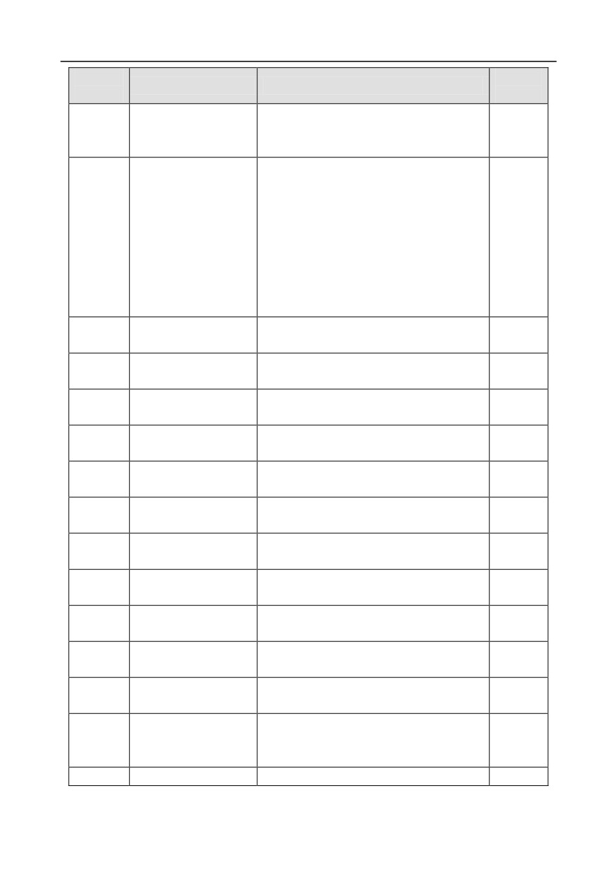
Related parameter list:
Function
Default
Name
Detailed parameter description
code
value
0:SVC 0
1:SVC 1
2:SVPWM
P00.00
Speed control mode
3:VC
2
Note: If 0, 1 or 3 is selected, it is required
to carry out motor parameter autotuning
first.
0: Keypad
Running command
P00.01
1: Terminal
0
channel
2: Communication
0:MODBUS
1:PROFIBUS/CANopen/Devicenet
Communication running
2:Ethernet
P00.02
0
command channel
3:EtherCat/Profinet
4:PLC programmable card
5:Bluetooth card
0: No operation
1: Rotary autotuning; carry out
comprehensive motor parameter autotuning;
rotary autotuning is used in cases where high
control precision is required;
Motor parameter
P00.15
2: Static autotuning 1 (comprehensive
0
autotuning
autotuning); static autotuning 1 is used in
cases where the motor cannot be
disconnected from load;
3: Static autotuning 2 (partial autotuning) ;
when current motor is motor 1, only P02.06,
-53-
Chapter 5
Function
Default
Name
Detailed parameter description
code
value
P02.07 and P02.08 will be autotuned; when
current motor is motor 2, only P12.06,
P12.07 and P12.08 will be autotuned.
0: No operation
1: Restore to default value
2: Clear fault history
Note: After the selected function
Function parameter
P00.18
operations are done, this function code
0
restoration
will be restored to 0 automatically.
Restoration to default value will clear the
user password, this function should be
used with caution.
0: Asynchronous motor
P02.00
Type of motor 1
0
1: Synchronous motor
Rated power of
Depend
P02.01
0.1-3000.0kW
asynchronous motor 1
on model
Rated frequency of
P02.02
0.01Hz-P00.03 (max. output frequency)
50.00Hz
asynchronous motor 1
Rated speed of
Depend
P02.03
1-36000rpm
asynchronous motor 1
on model
Rated voltage of
Depend
P02.04
0-1200V
asynchronous motor 1
on model
Rated current of
Depend
P02.05
0.8-6000.0A
asynchronous motor 1
on model
Rated power of
Depend
P02.15
0.1-3000.0kW
synchronous motor 1
on model
Rated frequency of
P02.16
0.01Hz-P00.03 (max. output frequency)
50.00Hz
synchronous motor 1
Number of pole pairs of
P02.17
1-50
2
synchronous motor 1
Rated voltage of
Depend
P02.18
0-1200V
synchronous motor 1
on model
Rated current of
Depend
P02.19
0.8-6000.0A
synchronous motor 1
on model
Function of multi-function
36: Command switches to keypad
P05.01-
digital input terminal
37: Command switches to terminal
/
P05.06
(S1-S4, HDIA, HDIB)
38: Command switches to communication
P07.01
Reserved variables
/
/
-54-

Chapter 5
Function
Default
Name
Detailed parameter description
code
value
Range: 0x00-0x27
Ones: QUICK/JOG key function selection
0: No function
1: Jogging
2: Reserved
3: Switching between forward/reverse
P07.02
QUICK/JOG key function rotation
0x01
4: Clear UP/DOWN setting
5: Coast to stop
6: Switch running command reference mode
by sequence
7: Reserved
Tens: Reserved
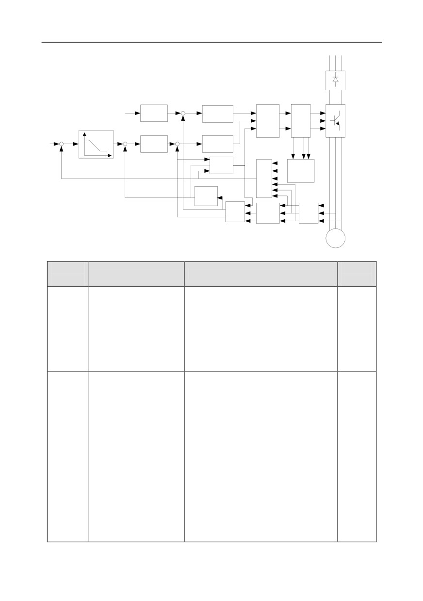
5.5.3 Vector control
Asynchronous motors are featured with high order, non-linear, strong coupling and multi-variables,
which makes it very difficult to control asynchronous motors during actual application. The vector
control theory aims to solve this problem through measuring and controlling the stator current vector
of asynchronous motor, and decomposing the stator current vector into exciting current (current
component which generates internal magnet field) and torque current (current component which
generates torque) based on field orientation principle, and then controlling the amplitude value and
phase position of these two components (namely, control the stator current vector of motor) to realize
decoupling control of exciting current and torque current, thus achieving high-performance speed
regulation of asynchronous motor.
GD350 series inverter carries built-in speed sensor-less vector control algorithm, which can be used
to drive the asynchronous motor and permanent-magnet synchronous motor simultaneously. As the
core algorithm of vector control is based on accurate motor parameter model, the accuracy of motor
parameters will impact the control performance of vector control. It is recommended to input accurate
motor parameters and carry out motor parameter autotuning before vector operation.
As vector control algorithm is complicated, users should be cautious of regulation on dedicated
function parameters of vector control.
-55-
Chapter 5
R S T
Rectifier
bridge
φ
+
ACR
Calculate im
exciting
-
current
Park
PWM
conversion
pulse
IGBT
bridge
+
+
ACR
Calculate iT
torque current
Uu UW
UV
-
-
iT
φ
Position
Uu
1wr
observation
UV
Voltage
Speed
detection
1wr
identific
UW
ation
Flux linkage
observation
iU
Park
conversio
Clark
Current
iV
iM
n
conversion
detection
iW
iT
Motor
Function
Default
Name
Detailed parameter description
code
value
0:SVC 0
1:SVC 1
2:SVPWM
P00.00
Speed control mode
3:VC
2
Note: If
0,
1 or
3 is selected, it is
required to carry out motor parameter
autotuning first.
0: No operation
1: Rotary autotuning; carry out
comprehensive motor parameter
autotuning; rotary autotuning is used in
cases where high control precision is
required;
Motor parameter
2: Static autotuning 1 (comprehensive
P00.15
0
autotuning
autotuning); static autotuning 1 is used in
cases where the motor cannot be
disconnected from load;
3: Static autotuning 2 (partial autotuning) ;
when current motor is motor 1, only
P02.06, P02.07 and P02.08 will be
autotuned; when current motor is motor 2,
-56-
Chapter 5
Function
Default
Name
Detailed parameter description
code
value
only P12.06, P12.07 and P12.08 will be
autotuned.
0: Asynchronous motor
P02.00
Type of motor 1
0
1: Synchronous motor
Speed loop proportional
P03.00
0-200.0
20.0
gain 1
P03.01
Speed loop integral time 1
0.000-10.000s
0.200s
Switching low point
P03.02
0.00Hz-P03.05
5.00Hz
frequency
Speed loop proportional
P03.03
0-200.0
20.0
gain 2
P03.04
Speed loop integral time 2
0.000-10.000s
0.200s
Switching high point
P03.05
P03.02-P00.03 (max. output frequency)
10.00Hz
frequency
P03.06
Speed loop output filter
0-8 (corresponds to 0-28/10ms)
0
Electromotion slip
P03.07
compensation coefficient of
50%-200%
100%
vector control
Brake slip compensation
P03.08
50%-200%
100%
coefficient of vector control
Current loop proportional
P03.09
0-65535
1000
coefficient P
Current loop integral
P03.10
0-65535
1000
coefficient I
0:Disable
P03.32
Torque control enable
0
1:Enable
1: Set via keypad (P03.12)
2: Set via AI1 (100% corresponds to three
times of rated motor current)
3: Set via AI2 (the same as above)
4: Set via AI3 (the same as above)
Torque setup mode
5: Set via pulse frequency HDIA (the same
P03.11
1
selection
as above)
6: Set via multi-step torque (the same as
above)
7: Set via MODBUS communication (the
same as above)
8: Set via PROFIBUS/CANopen/DeviceNet
-57-

Chapter 5
Function
Default
Name
Detailed parameter description
code
value
communication (the same as above)
9: Set via Ethernet communication (the
same as above)
10: Set via pulse frequency HDIB (the
same as above)
11: Set via EtherCat/Profinet
communication
12: Set via PLC
Note: Set mode 2-12, 100% corresponds
to three times of rated motor current.
P03.12
Torque set by keypad
-300.0%-300.0% (rated motor current)
50.0%
P03.13
Torque reference filter time
0.000-10.000s
0.010s
0: Keypad (P03.16)
1: AI1
(100% corresponds to max.
frequency)
2: AI2 (the same as above)
3: AI3 (the same as above)
4: Pulse frequency HDIA (the same as
above)
5: Multi-step (the same as above)
6: MODBUS communication (the same as
Source of upper limit
above)
P03.14
frequency setup of forward
7: PROFIBUS /CANopen/ DeviceNet
0
rotation in torque control
communication (the same as above)
8: Ethernet communication (the same as
above)
9: Pulse frequency HDIB (the same as
above)
10: EtherCat/Profinet communication
11: PLC
12: Reserved
Note: Source 1-11, 100% relative to the
max. frequency
Source of upper limit
0: Keypad (P03.17)
P03.15
frequency setup of reverse
0
1-11: the same as P03.14
rotation in torque control
Keypad limit value of upper
Value range: 0.00 Hz-P00.03 (max. output
P03.16
limit frequency of forward
50.00Hz
frequency)
rotation in torque control
-58-
Chapter 5
Function
Default
Name
Detailed parameter description
code
value
Keypad limit value of upper
P03.17
limit frequency of reverse
50.00Hz
rotation in torque control
0: Keypad (P03.20)
1: AI1
(100% relative to three times of
motor current)
2: AI2 (the same as above)
3: AI3 (the same as above)
4: Pulse frequency HDIA (the same as
above)
5: MODBUS communication (the same as
above)
Source of upper limit setup
6: PROFIBUS/CANopen/DeviceNet
P03.18
of the torque when
0
communication (the same as above)
motoring
7: Ethernet communication (the same as
above)
8: Pulse frequency HDIB (the same
as
above)
9: EtherCat/Profinet communication
10: PLC
11: Reserved
Note: Source
1-10,
100% relative
to
three times of motor current.
Source of upper limit setup
0: Keypad (P03.21)
P03.19
0
of brake torque
1-10: the same as P03.18
Set upper limit of the torque
P03.20
180.0%
when motoring via keypad
0.0-300.0% (rated motor current)
Set upper limit of brake
P03.21
180.0%
torque via keypad
Flux-weakening coefficient
P03.22
0.1-2.0
0.3
in constant power area
Min. flux-weakening point
P03.23
10%-100%
20%
in constant power area
P03.24
Max. voltage limit
0.0-120.0%
100.0%
P03.25
Pre-exciting time
0.000-10.000s
0.300s
P17.32
Flux linkage
0.0-200.0%
0.0%
5.5.4 SVPWM control mode
GD350 inverter also carries built-in SVPWM control function. SVPWM mode can be used in cases
-59-
Chapter 5
where mediocre control precision is enough. In cases where an inverter needs to drive multiple
motors, it is also recommended to adopt SVPWM control mode.
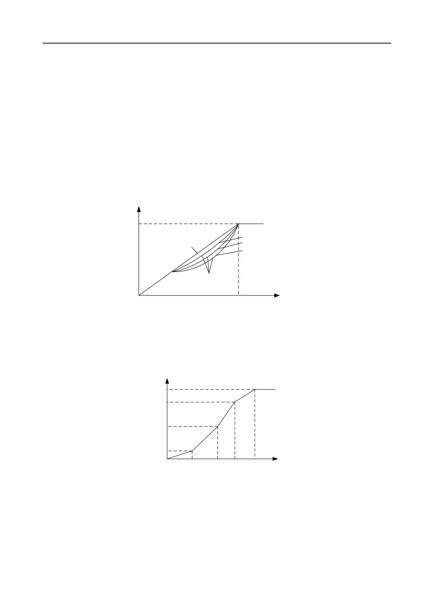
GD350 inverter provides multiple kinds of V/F curve modes to meet different field needs. Users can
select corresponding V/F curve or set the V/F curve as needed.
Suggestions:
1.
For the load featuring constant moment, eg, conveyor belt which runs in straight line, as
the moment should be constant during the whole running process, it is recommended to
adopt straight-type V/F curve.
2.
For the load featuring decreasing moment, eg, fan and water pump, as the relation
between its actual torque and speed is squared or cubed, it is recommended to adopt the V/F
curve corresponds to power 1.3, 1.7 or 2.0.
Output voltage
Vb
Torque -down V/F curve (1.3th order)
Straight-type
Torque -down V/F curve (1.7th order)
Torque -down V/F curve (2.0th order)
Square-type
Output frequency
f
b
GD350 inverter also provides multi-point V/F curve. Users can alter the V/F curve outputted by
inverter through setting the voltage and frequency of the three points in the middle. The whole curve
consists of five points starting from (0Hz, 0V) and ending in (fundamental motor frequency, rated
motor voltage). During setup, it is required that
0≤f1≤f2≤f3≤fundamental motor frequency, and
0≤V1≤V2≤V3≤rated motor voltage
Output voltage
100%
V
b
V3
V2
V1
f1
f2
f3
f
Output frequency
b
Hz
GD350 inverter provides dedicated function codes for SVPWM control mode. Users can improve the
performance of SVPWM through settings.
1.
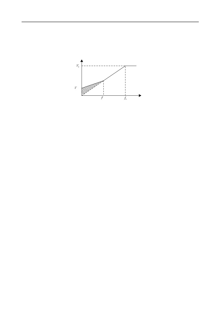
Torque boost
Torque boost function can effectively compensate for the low-speed torque performance during
SVPWM control. Automatic torque boost has been set by default to enable the inverter to adjust the
torque boost value based on actual load conditions.
-60-
Chapter 5
Note:
(1)
Torque boost is effective only under torque boost cut-off frequency;
(2)
If the torque boost is too large, low-frequency vibration or overcurrent may occur to the motor, if
such situation occurs, lower the torque boost value.
Output voltage V
boost
cut-off
Output frequency f
2.
Energy-saving run
During actual running, the inverter can search for the max. efficiency point to keep running in the most
efficient state to save energy.
Note:
(1)
This function is generally used in light load or no-load cases.
(2)
This function does for fit in cases where load transient is required.
3.
V/F slip compensation gain
SVPWM control belongs to open-loop mode, which will cause motor speed to fluctuate when motor
load transients. In cases where strict speed requirement is needed, users can set the slip
compensation gain to compensate for the speed variation caused by load fluctuation through
internal output adjustment of inverter.
The set range of slip compensation gain is 0-200%, in which 100% corresponds to rated slip
frequency.
Note: Rated slip frequency= (rated synchronous speed of motor-rated speed of motor) × number of
motor pole pairs/60
4.
Oscillation control
Motor oscillation often occurs in SVPWM control in large-power drive applications. To solve this
problem, GD350 series inverter sets two function codes to control the oscillation factor, and users can
set the corresponding function code based on the occurrence frequency of oscillation.
Note: The larger the set value, the better the control effect, however, if the set value is too large, it
may easily lead to too large inverter output current.
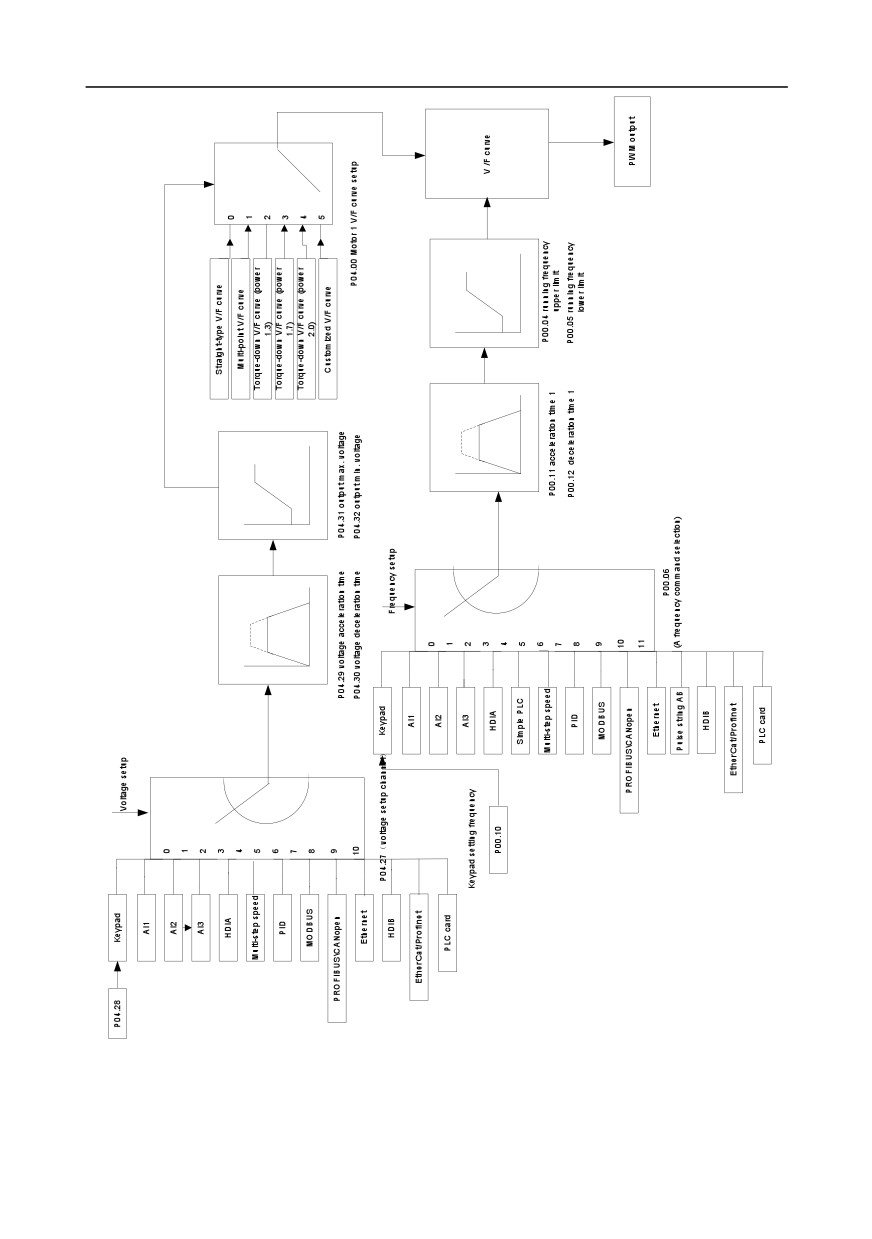
Customized V/F curve (V/F separation) function:
-61-
Chapter 5
When selecting customized V/F curve function, users can set the reference channels and
acceleration/deceleration time of voltage and frequency respectively, which will form a real-time V/F
curve through combination.
-62-
Chapter 5
Note: This kind of V/F curve separation can be applied in various frequency-conversion power
sources, however, users should be cautious of parameter setup as improper setup may damage the
machine.
Function
Default
Name
Detailed parameter description
code
value
0:SVC 0
1:SVC 1
2:SVPWM
P00.00
Speed control mode
2
3:VC
Note: If 0, 1 or 3 is selected, it is required to
carry out motor parameter autotuning first.
P00.03
Max. output frequency
P00.04-400.00Hz
50.00Hz
Upper limit of running
P00.04
P00.05-P00.03
50.00Hz
frequency
Lower limit of running
P00.05
0.00Hz-P00.04
0.00Hz
frequency
Depend on
P00.11
Acceleration time 1
0.0-3600.0s
model
Depend on
P00.12
Deceleration time 1
0.0-3600.0s
model
0: Asynchronous motor
P02.00
Type of motor 1
0
1: Synchronous motor
Rated power of asynchronous
P02.02
0.01Hz-P00.03 (max. output frequency)
50.00Hz
motor 1
Rated voltage of
Depend on
P02.04
0-1200V
asynchronous motor 1
model
0: Straight-type V/F curve
1: Multi-point V/F curve
2: Torque-down V/F curve (power 1.3)
P04.00
V/F curve setting of motor 1
0
3: Torque-down V/F curve (power 1.7)
4: Torque-down V/F curve (power 2.0)
5: Customized V/F (V/F separation)
P04.01
Torque boost of motor 1
0.0%: (automatic) 0.1%-10.0%
0.0%
P04.02
Motor 1 torque boost cut-off
0.0%-50.0% (rated frequency of motor 1)
20.0%
V/F frequency point 1 of
P04.03
0.00Hz-P04.05
0.00Hz
motor 1
P04.04
V/F voltage point 1 of motor 1
0.0%-110.0%
0.0%
V/F frequency point 2 of
P04.05
P04.03- P04.07
0.00Hz
motor 1
P04.06
V/F voltage point 2 of motor 1
0.0%-110.0%
0.0%
-63-

Chapter 5
Function
Default
Name
Detailed parameter description
code
value
V/F frequency point 3 of
P04.07
P04.05- P02.02 or P04.05- P02.16
0.00Hz
motor 1
P04.08
V/F voltage point 3 of motor 1
0.0%-110.0%
0.0%
V/F slip compensation gain of
P04.09
0.0-200.0%
100.0%
motor 1
Low-frequency oscillation
P04.10
0-100
10
control factor of motor 1
High-frequency oscillation
P04.11
0-100
10
control factor of motor 1
Oscillation control threshold
P04.12
0.00Hz-P00.03 (max. output frequency)
30.00Hz
of motor 1
0: Straight V/F curve;
1: Multi-point V/F curve
2: Torque-down V/F curve (1.3th order)
P04.13
V/F curve setup of motor 2
0
3: Torque-down V/F curve (1.7th order)
4: Torque-down V/F curve (2.0th order)
5: Customize V/F (V/F separation)
P04.14
Torque boost of motor 2
0.0%: (automatic) 0.1%-10.0%
0.0%
P04.15
Motor 2 torque boost cut-off
0.0%-50.0% (rated frequency of motor 1)
20.0%
V/F frequency point 1 of
P04.16
0.00Hz-P04.18
0.00Hz
motor 2
P04.17
V/F voltage point 1 of motor 2
0.0%-110.0%
0.0%
V/F frequency point 2 of
P04.18
P04.16- P04.20
0.00Hz
motor 2
P04.19
V/F voltage point 2 of motor 2
0.0%-110.0%
0.0%
V/F frequency point 3 of
P04.20
P04.18- P02.02 or P04.18- P02.16
0.00Hz
motor 2
P04.21
V/F voltage point 3 of motor 2
0.0%-110.0%
0.0%
V/F slip compensation gain of
P04.22
0.0-200.0%
100.0%
motor 2
Low-frequency oscillation
P04.23
0-100
10
control factor of motor 2
High-frequency oscillation
P04.24
0-100
10
control factor of motor 2
Oscillation control threshold
P04.25
0.00Hz-P00.03 (max. output frequency)
30.00Hz
of motor 2
0: No
P04.26
Energy-saving run
0
1: Automatic energy-saving run
-64-
Chapter 5
Function
Default
Name
Detailed parameter description
code
value
0: Keypad; output voltage is determined by
P04.28
1: AI1
2: AI2
3: AI3
4: HDIA
5: Multi-step
P04.27
Channel of voltage setup
6: PID
0
7: MODBUS communication
8: PROFIBUS/CANopen communication
9: Ethernet communication
10: HDIB
11: EtherCat/Profinet communication
12: PLC card
13: Reserved
P04.28
Set voltage value via keypad
0.0%-100.0% (rated motor voltage)
100.0%
P04.29
Voltage increase time
0.0-3600.0s
5.0s
P04.30
Voltage decrease time
0.0-3600.0s
5.0s
P04.31
Output max. voltage
P04.32-100.0% (rated motor voltage)
100.0%
P04.32
Output min. voltage
0.0%-P04.31 (rated motor voltage)
0.0%
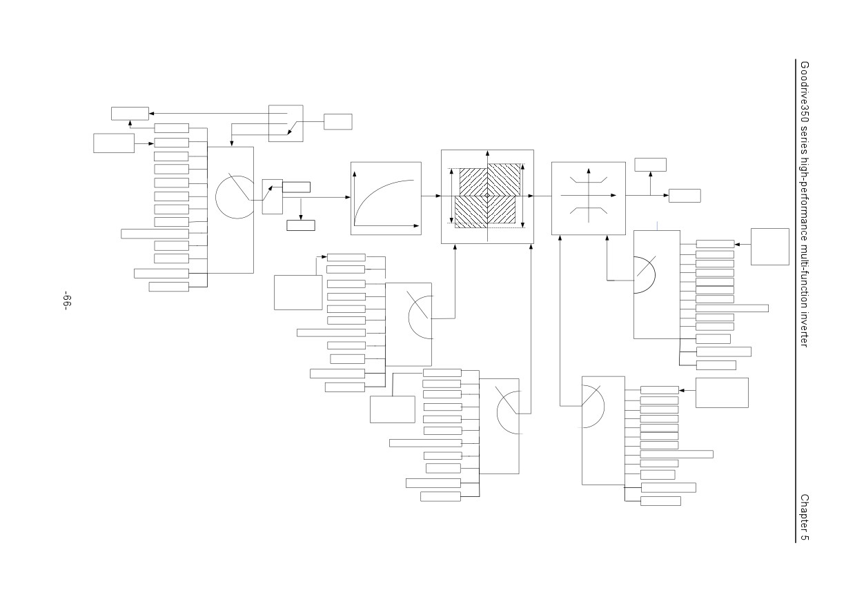
5.5.5 Torque control
GD350 inverter supports torque control and speed control. Speed control mode aims to stabilize the
speed to keep the set speed consistent with the actual running speed, meanwhile, the max.
load-carrying capacity is restricted by torque limit. Torque control mode aims to stabilize the torque to
keep the set torque consistent with the actual output torque, meanwhile, the output frequency is
restricted by upper/lower limit.
-65-
P00.00 (Speed control mode)
Speed control
2
1
Start
Invalid
0
P03.12
Torque set by
Keypad
keypad
P03.13
Set upper limit
0
Output torque
AI1
Torque reference filter time
Motorin
Torque control limit
1
Terminal function 29
g
P17.09
AI2
Switching between torque control
2
and speed control
AI3
3
Valid
Speed
Upper
4
control
Upper
limit of the
limit of
torque
Torque
HDIA
5
Invalid
brake
during
control
torque
motoring
Multi-step speed
6
P03.14
7
(Source of upper limit frequency setup
MODBUS
of forward rotation in torque control)
8
P17.15
PROFIBUS\CANopen
Brake
P03.16
9
Torque reference
Keypad limit value
Ethernet
10
value
0
Keypad
of upper limit
frequency of
1
AI1
forward rotation in
HDIB
Keypad
torque control
2
AI2
AI1
P03.19
EtherCat/Profinet
P03.11
(Source of upper limit setup of
3
AI3
Torque setup mode
AI2
brake torque)
4
HDIA
PLC card
selection
P03.21
Set upper limit of brake
0
5
Multi-step speed
torque via keypad
AI3
1
MODBUS
6
HDIA
2
7
PROFIBUS\CANopen
MODBUS
3
8
Ethernet
4
9
Reserved
PROFIBUS\CANopen
5
HDIB
Ethernet
6
P03.18
7
(Source of upper limit setup of the
EtherCat/Profinet
HDIB
torque when motoring)
P03.15
8
(Source of upper limit frequency setup
PLC card
EtherCat/Profinet
Keypad
of reverse rotation in torque control)
AI1
P03.17
PLC card
Keypad
Keypad limit value of
AI2
0
0
upper limit frequency of
P03.20
1
1
AI1
reverse rotation in torque
Set upper limit of the
AI3
control
torque when motoring
2
2
AI2
via keypad
HDIA
3
3
AI3
MODBUS
4
4
HDIA
5
5
Multi-step speed
PROFIBUS\CANopen
MODBUS
6
6
Ethernet
7
7
PROFIBUS\CANopen
8
8
Ethernet
HDIB
9
HDIB
EtherCat/Profinet
EtherCat/Profinet
PLC card
PLC card

Chapter 5
Function
Default
Name
Detailed parameter description
code
value
0:SVC 0
1:SVC 1
Speed control
2:SVPWM
P00.00
2
mode
3:VC
Note: If 0, 1 or 3 is selected, it is required to
carry out motor parameter autotuning first.
Torque control
0:Disable
P03.32
0
enable
1:Enable
0: Set via keypad (P03.12)
1: Set via keypad (P03.12)
2: Set via AI1 (100% corresponds to three times
of rated motor current)
3: Set via AI2 (the same as above)
4: Set via AI3 (the same as above)
5: Set via pulse frequency HDIA (the same as
above)
6: Set via multi-step torque (the same as above)
7: Set via MODBUS communication (the same
Torque setup
P03.11
as above)
0
mode selection
8: Set via PROFIBUS/CANopen/DeviceNet
communication (the same as above)
9: Set via Ethernet communication (the same as
above)
10: Set via pulse frequency HDIB (the same as
above)
11: Set via EtherCat/Profinet communication
12: Set via PLC
Note: Set mode 2-12, 100% corresponds to
three times of rated motor current.
Torque set by
P03.12
-300.0%-300.0% (rated motor current)
50.0%
keypad
Torque reference
P03.13
0.000-10.000s
0.010s
filter time
0: Keypad (P03.16)
Source of upper
1: AI1 (100% corresponds to max. frequency)
limit frequency
2: AI2 (the same as above)
P03.14
setup of forward
0
3: AI3 (the same as above)
rotation in torque
4: Pulse frequency HDIA (the same as above)
control
5: Multi-step (the same as above)
-67-

Chapter 5
Function
Default
Name
Detailed parameter description
code
value
6: MODBUS communication
(the same as
above)
7: PROFIBUS /CANopen/ DeviceNet
communication (the same as above)
8: Ethernet communication (the same as above)
9: Pulse frequency HDIB (the same as above)
10: EtherCat/Profinet communication
11: PLC
12: Reserved
Note: Source 1-11, 100% relative to the max.
frequency
0: Keypad (P03.17)
1: AI1 (100% corresponds to max. frequency)
2: AI2 (the same as above)
3: AI3 (the same as above)
4: Pulse frequency HDIA (the same as above)
5: Multi-step (the same as above)
Source of upper
6: MODBUS communication
(the same as
limit frequency
above)
P03.15
setup of reverse
7: PROFIBUS /CANopen/ DeviceNet
0
rotation in torque
communication (the same as above)
control
8: Ethernet communication (the same as above)
9: Pulse frequency HDIB (the same as above)
10: EtherCat/Profinet communication
11: PLC
12: Reserved
Note: Source 1-11, 100% relative to the max.
frequency
Keypad limit value
of upper limit
P03.16
frequency of
0.00Hz-P00.03 (max. output frequency)
50.00 Hz
forward rotation in
torque control
Keypad limit value
of upper limit
P03.17
frequency of
0.00Hz-P00.03 (max. output frequency)
50.00 Hz
reverse rotation in
torque control
P03.18
Source of upper
0: Keypad (P03.20)
0
-68-

Chapter 5
Function
Default
Name
Detailed parameter description
code
value
limit setup of the
1: AI1 (100% relative to three times of motor
torque during
current)
motoring
2: AI2 (the same as above)
3: AI3 (the same as above)
4: Pulse frequency HDIA (the same as above)
5: MODBUS communication
(the same as
above)
6: PROFIBUS/CANopen/DeviceNet
communication (the same as above)
7: Ethernet communication (the same as above)
8: Pulse frequency HDIB (the same as above)
9: EtherCat/Profinet communication
10: PLC
11: Reserved
Note: Source
1-10,
100% relative to three
times of motor current.
0: Keypad (P03.21)
1: AI1 (100% relative to three times of motor
current)
2: AI2 (the same as above)
3: AI3 (the same as above)
4: Pulse frequency HDIA (the same as above)
5: MODBUS communication
(the same as
Source of upper
above)
P03.19
limit setup of brake
6: PROFIBUS/CANopen/DeviceNet
0
torque
communication (the same as above)
7: Ethernet communication (the same as above)
8: Pulse frequency HDIB (the same as above)
9: EtherCat/Profinet communication
10: PLC
11: Reserved
Note: Source
1-10,
100% relative to three
times of motor current.
Set upper limit of
the torque when
P03.20
0.0-300.0% (rated motor current)
180.0%
motoring via
keypad
Set upper limit of
P03.21
0.0-300.0% (rated motor current)
180.0%
brake torque via
-69-
Chapter 5
Function
Default
Name
Detailed parameter description
code
value
keypad
Motor output
P17.09
-250.0-250.0%
0.0%
torque
Torque reference
P17.15
-300.0-300.0% (rated motor current)
0.0%
value
5.5.6 Motor parameter
Check the safety conditions surrounding the motor and load machineries
before autotuning as physical injury may occur due to sudden start of motor during
autotuning.
Although the motor does not run during static autotuning, the motor is stilled
supplied with power, do not touch the motor during autotuning; otherwise, electric
shock may occur.
If the motor has been connected to load, do not carry out rotary autotuning;
otherwise, misact or damage may occur to the inverter. If rotary autotuning is carried
out on a motor which has been connected to load, wrong motor parameters and
motor misacts may occur. Disconnect the load to carry out autotuning if necessary.
GD350 inverter can drive asynchronous motors and synchronous motors, and it supports two sets of
motor parameters, which can be switched over by multi-function digital input terminals or
communication modes.
-70-
Chapter 5
Start
Select running
command channel
(P00.01)
Terminal
Communication
Keypad (P00.01=0)
(P00.01=1)
(P00.01=2)
P08.31 set LED
The switch-over
ones to 0
channel for motor 1 and
motor 2 (P08.31)
P08.31 sets
P08.31 sets
ones to 2
ones to 3
Terminal function 35
PROFIBUS
MODBUS
Ethernet
Motor 1 switches to
CANopen
P08.31 set LED
communication
communication
motor 2
communication
ones to 1
Communication setting value
2009H
Invalid
Valid
BIT0-1=00
BIT0-1=01
Motor 1
Motor 2
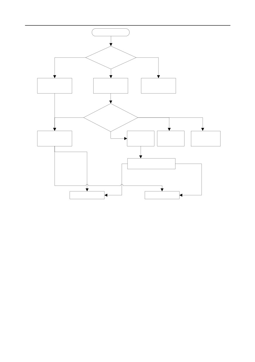
The control performance of the inverter is based on accurate motor model, therefore, users need to
carry out motor parameter autotuning before running the motor for the first time (take motor 1 as an
example)
-71-
Chapter 5
Ready
P00.01=0 (controlled by
keypad)
Synchronous
Asynchronous
motor
Motor type
motor
(P02.00)
P02.00=1
P02.00=0
Input motor nameplate
Input motor nameplate
(P02.15-P02.19)
(P02.01-P02.05)
Set autotuning mode
(P00.15)
Complete parameter
Complete parameter
Partial parameter rotary
rotary autotuning
static autotuning
autotuning
Press "RUN" key to start
autotuning
During autotuning
Autotuning finished
Note:
1. Motor parameters must be set correctly according to motor nameplate;
2. If rotary autotuning is selected during motor autotuning, it is a must to disconnect the motor from
load to put the motor in static and no-load state, failed to do so may lead to inaccurate autotuned
results. At this time, the asynchronous motor can autotune P02.06-P02.10, and synchronous
motor can autotune P02.20-P02.23
3. If static autotuning is selected during motor autotuning, there is no need to disconnect the motor
-72-

Chapter 5
from load, as only part of the motor parameters have been autotuned, the control performance
may be impacted, under such situation, the asynchronous motor can autotune P02.06-P02.10,
while synchronous motor can autotune P02.20-P02.22, P02.23
(counter-emf constant of
synchronous motor 1) can be obtained via calculation.
4. Motor autotuning can be carried out on current motor only, if users need to perform autotuning on
the other motor, switch over the motor through selecting the switch-over channel of motor 1 and
motor 2 by setting the ones of P08.31.
Related parameter list:
Function
Default
Name
Detailed parameter description
code
value
0: Keypad
P00.01
Running command channel
1: Terminal
0
2: Communication
0: No operation
1: Rotary autotuning; carry out
comprehensive motor parameter
autotuning; rotary autotuning is used in
cases where high control precision is
required;
2: Static autotuning 1 (comprehensive
autotuning); static autotuning 1 is used in
P00.15
Motor parameter autotuning
0
cases where the motor cannot be
disconnected from load;
3: Static autotuning 2 (partial
autotuning) ; when current motor is motor
1, only P02.06, P02.07 and P02.08 will
be autotuned; when current motor is
motor 2, only P12.06, P12.07 and P12.08
will be autotuned.
0: Asynchronous motor
P02.00
Type of motor 1
0
1: Synchronous motor
Rated power of
Depend
P02.01
0.1-3000.0kW
asynchronous motor 1
on model
Rated frequency of
P02.02
0.01Hz-P00.03 (max. output frequency)
50.00Hz
asynchronous motor 1
Rated speed of
Depend
P02.03
1-36000rpm
asynchronous motor 1
on model
Rated voltage of
Depend
P02.04
0-1200V
asynchronous motor 1
on model
P02.05
Rated current of
0.8-6000.0A
Depend
-73-
Chapter 5
Function
Default
Name
Detailed parameter description
code
value
asynchronous motor 1
on model
Stator resistance of
Depend
P02.06
0.001-65.535Ω
asynchronous motor 1
on model
Rotor resistance of
Depend
P02.07
0.001-65.535Ω
asynchronous motor 1
on model
Leakage inductance of
Depend
P02.08
0.1-6553.5mH
asynchronous motor 1
on model
Mutual inductance of
Depend
P02.09
0.1-6553.5mH
asynchronous motor 1
on model
No-load current of
Depend
P02.10
0.1-6553.5A
asynchronous motor 1
on model
Rated power of synchronous
Depend
P02.15
0.1-3000.0kW
motor 1
on model
Rated frequency of
P02.16
0.01Hz-P00.03 (max. output frequency)
50.00Hz
synchronous motor 1
Number of pole pairs of
P02.17
1-50
2
synchronous motor 1
Rated voltage of
Depend
P02.18
0-1200V
synchronous motor 1
on model
Rated current of
Depend
P02.19
0.8-6000.0A
synchronous motor 1
on model
Stator resistance of
Depend
P02.20
0.001-65.535Ω
synchronous motor 1
on model
Direct-axis inductance of
Depend
P02.21
0.01-655.35mH
synchronous motor 1
on model
Quadrature-axis inductance
Depend
P02.22
0.01-655.35mH
of synchronous motor 1
on model
Counter-emf constant of
P02.23
0-10000
300
synchronous motor 1
Function of multi-function
P05.01-
digital input terminal (S1-S4,
35: Motor 1 switches to motor 2
/
P05.06
HDIA,HDIB)
0x00-0x14
Ones: Switch-over channel
Switching between motor 1
0: Switch over by terminal
P08.31
00
and motor 2
1: Switch over by MODBUS
communication
2: Switch over by PROFIBUS / CANopen
-74-