Goodrive350 Series High-performance Multi-function Inver ter. Operation manual - page 5
Chapter 6
Function
Default
Modi
Name
Detailed parameter description
code
value
fy
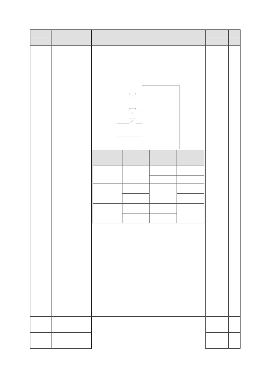
running direction. During running, the terminal Sin
should be closed, and terminal FWD or REV
generates a rising edge signal to control the running
and direction of inverter; the inverter should be
stopped by disconnecting terminal Sin.
SB1
FWD
SB2
Sln
SB3
REV
COM
Running
Sln
FWD
REV
direction
ON
Forward
ON
OFF→ON
OFF
Forward
ON
Reverse
ON
OFF→ON
OFF
Reverse
Decelerate
ON→OFF
to stop
Sln:
3-Wire control/Sin, FWD: Forward running,
REV: Reverse running
Note: For dual-line running mode, when
FWD/REV terminal is valid, if the inverter stops
due to stop command given by other sources, it
will not run again after the stop command
disappears even if the control terminals
FWD/REV are still valid. To make the inverter run
again, users need to trigger FWD/REV again, eg,
PLC single-cycle stop, fixed-length stop, and
valid STOP/RST stop during terminal control.
(see P07.04)
S1 terminal
P05.12
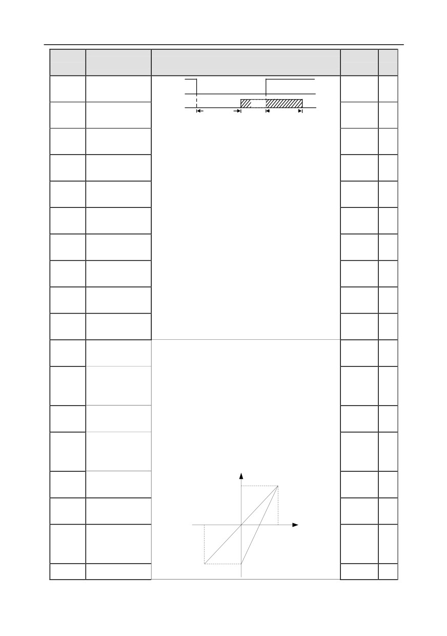
These function codes define corresponding delay of
0.000s
○
switch-on delay
the programmable input terminals during level
S1 terminal
P05.13
variation from switch-on to switch-off .
0.000s
○
switch-off delay
-155-
Chapter 6
Function
Default
Modi
Name
Detailed parameter description
code
value
fy
S2 terminal
Si electrical level
P05.14
0.000s
○
switch-on delay
Si valid
invalid
valid
invalid
S2 terminal
P05.15
Switcn-on
Switcn-off
0.000s
○
switch-off delay
delay
delay
S3 terminal
P05.16
Setting range: 0.000-50.000s
0.000s
○
switch-on delay
S3 terminal
P05.17
0.000s
○
switch-off delay
S4 terminal
P05.18
0.000s
○
switch-on delay
S4 terminal
P05.19
0.000s
○
switch-off delay
HDIA terminal
P05.20
0.000s
○
switch-on delay
HDIA terminal
P05.21
0.000s
○
switch-off delay
HDIB terminal
P05.22
0.000s
○
switch-on delay
HDIB terminal
P05.23
0.000s
○
switch-off delay
Lower limit value
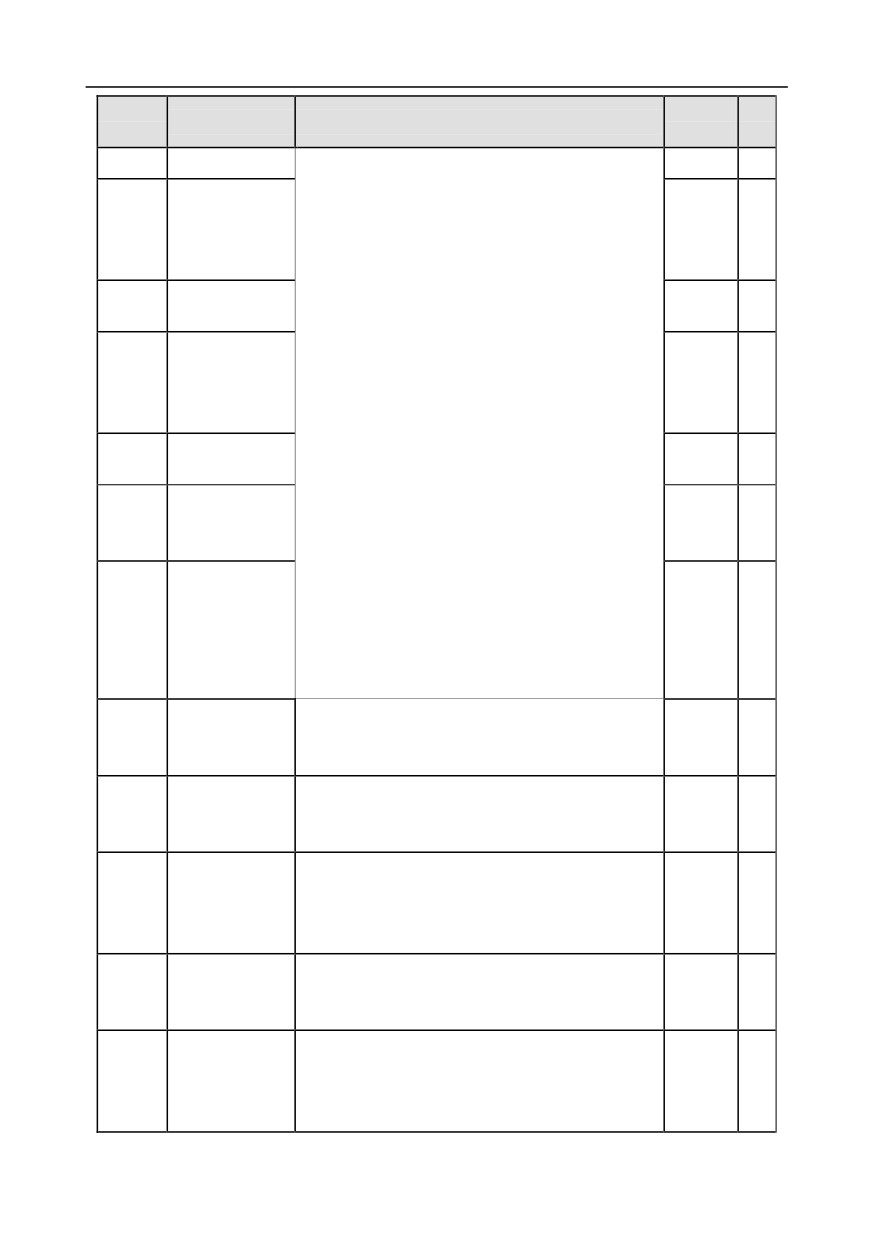
These function codes define the relation between
P05.24
0.00V
○
of AI1
analog input voltage and corresponding set value of
Corresponding
analog input. When the analog input voltage
P05.25
setting of lower
exceeds the range of max./min. input, the max. input
0.0%
○
limit of AI1
or min. input will be adopted during calculation.
Upper limit value
When analog input is current input, 0-20mA current
P05.26
10.00V
○
of AI1
corresponds to 0-10V voltage.
Corresponding
In different applications,
100% of analog setting
P05.27
setting of upper
corresponds to different nominal values.
100.0%
○
limit of AI1
The figure below illustrates several settings.
Corresponding setting
Input filter time of
P05.28
100%
0.030s
○
AI1
Lower limit value
P05.29
-10.00V
○
of AI2
-10V
0
AI
10V
Corresponding
20mA
AI1
P05.30
setting of lower
AI2
-100.0%
○
limit of AI2
-100%
P05.31
Intermediate
0.00V
○
-156-
Chapter 6
Function
Default
Modi
Name
Detailed parameter description
code
value
fy
value 1 of AI2
Input filter time: Adjust the sensitivity of analog input,
increase this value properly can enhance the
Corresponding
anti-interference capacity of analog variables;
setting of
P05.32
0.0%
○
however, it will also degrade the sensitivity of analog
intermediate
input.
value 1 of AI2
Note: AI1 can support 0-10V/0-20mA input, when
Intermediate
P05.33
AI1 selects 0-20mA input; the corresponding voltage
0.00V
○
value 2 of AI2
of 20mA is 10V; AI2 supports -10V-+10V input.
Corresponding
Setting range of P05.24: 0.00V-P05.26
setting of
P05.34
Setting range of P05.25: -100.0%-100.0%
0.0%
○
intermediate
Setting range of P05.26: P05.24-10.00V
value 2 of AI2
Setting range of P05.27: -100.0%-100.0%
Upper limit value
P05.35
Setting range of P05.28: 0.000s-10.000s
10.00V
○
of AI2
Setting range of P05.29: -10.00V-P05.31
Corresponding
Setting range of P05.30: -100.0%-100.0%
P05.36
setting of upper
100.0%
○
Setting range of P05.31: P05.29-P05.33
limit of AI2
Setting range of P05.32: -100.0%-100.0%
Setting range of P05.33: P05.31-P05.35
Setting range of P05.34: -100.0%-100.0%
Input filter time of
P05.37
0.030s
○
Setting range of P05.35: P05.33-10.00V
AI2
Setting range of P05.36: -100.0%-100.0%
Setting range of P05.37: 0.000s-10.000s
HDIA high-speed
0: Set input via frequency
P05.38
pulse input
1: Reserved
0
◎
function
2: Input via encoder, used in combination with HDIB
Lower limit
0.000
P05.39
frequency of
0.000 KHz - P05.41
○
KHz
HDIA
Corresponding
setting of lower
P05.40
-100.0%-100.0%
0.0%
○
limit frequency of
HDIA
Upper limit
50.000
P05.41
frequency of
P05.39 -50.000KHz
○
KHz
HDIA
Corresponding
setting of upper
P05.42
-100.0%-100.0%
100.0%
○
limit frequency of
HDIA
-157-
Chapter 6
Function
Default
Modi
Name
Detailed parameter description
code
value
fy
HDIA frequency
P05.43
0.000s-10.000s
0.030s
○
input filter time
0: Set input via frequency
HDIB high-speed
1: Reserved
P05.44
pulse input
0
◎
2: Encoder input, it should be used in combination
function selection
with HDIA
Lower limit
0.000
P05.45
frequency of
0.000 KHz - P05.47
○
KHz
HDIB
Corresponding
setting of lower
P05.46
-100.0%-100.0%
0.0%
○
limit frequency of
HDIB
Upper limit
50.000
P05.47
frequency of
P05.45 -50.000KHz
○
KHz
HDIB
Corresponding
setting of upper
P05.48
-100.0%-100.0%
100.0%
○
limit frequency of
HDIB
HDIB frequency
P05.49
0.000s-10.000s
0.030s
○
input filter time
0-1
AI1 input signal
P05.50
0: Voltage type
0
◎
type
1: Current type
P05.51-
Reserved
0-65535
0
●
P05.52
variables
P06 group Output terminals
0: Open collector high-speed pulse output: Max.
frequency of the pulse is 50.00kHz. For details about
P06.00
HDO output type
the related functions, see P06.27-P06.31.
0
◎
1: Open collector output: For details about the
related functions, see P06.02.
Y output
0: Invalid
P06.01
0
○
selection
1: In running
HDO output
2: In forward running
P06.02
0
○
selection
3: In reverse running
P06.03
Relay RO1
4: In jogging
1
○
-158-
Chapter 6
Function
Default
Modi
Name
Detailed parameter description
code
value
fy
output selection
5: Inverter fault
6: Frequency level detection FDT1
7: Frequency level detection FDT2
8: Frequency reached
9: Running in zero speed
10: Reach upper limit frequency
11: Reach lower limit frequency
12: Ready to run
13: In pre-exciting
14: Overload pre-alarm
15: Underload pre-alarm
16: Simple PLC stage completed
17: Simple PLC cycle completed
18: Reach set counting value
19: Reach designated counting value
20: External fault is valid
21: Reserved
22: Reach running time
23: Virtual terminal output of MODBUS
Relay RO2
communication
P06.04
5
○
output selection
24: Virtual terminal output of POROFIBUS
/CANopen communication
25: Virtual terminal output of Ethernet
communication
26: DC bus voltage established
27: z pulse output
28: During pulse superposition
29: STO act
30: Positioning completed
31: Spindle zeroing completed
32: Spindle scale-division completed
33: In speed limit
34-35: Reserved
36: Speed/position control switch-over completed
37-40: Reserved
41: C_Y1 from CODESYS (set P27.00 to 1)
42: C_Y2 from CODESYS (set P27.00 to1)
43: C_HDO from CODESYS (set P27.00 to 1)
44: C_RO1 from CODESYS (set P27.00 to 1)
-159-
Chapter 6
Function
Default
Modi
Name
Detailed parameter description
code
value
fy
45: C_RO2 from CODESYS (set P27.00 to 1)
46: C_RO3 from CODESYS3 (set P27.00 to 1)
47: C_RO4 from CODESYS (set P27.00 to 1)
48-63: Reserved
29: STO action
48-63: Reserved
Output terminal
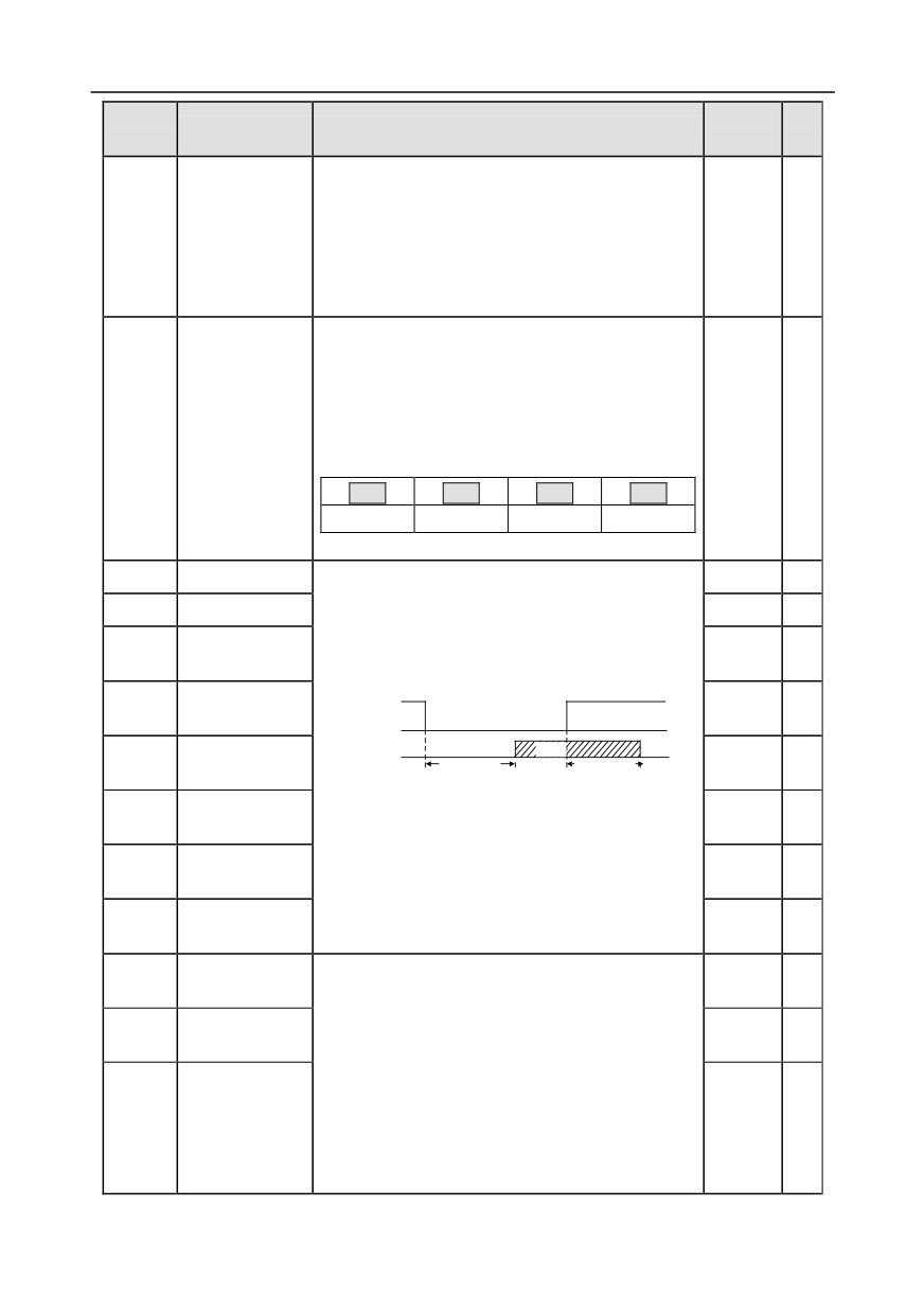
This function code is used to set the polarity of
polarity selection
output terminals.
When the bit is set to 0, input terminal polarity is
positive;
P06.05
When the bit is set to 1 input terminal polarity is
00
○
negative.
BIT3
BIT2
BIT1
BIT0
RO2
RO1
HDO
Y
Setting range: 0x0-0xF
P06.06
Y switch-on delay
0.000s
○
P06.07
Y switch-off delay
0.000s
○
HDO switch-on
P06.08
This function code defines the corresponding delay
0.000s
○
delay
of the level variation from switch-on to switch-off.
HDO switch-off
P06.09
Y electric level
0.000s
○
delay
invalid
Relay RO1
Y valid
Invalid
Valid
P06.10
Switch on
Switch off
0.000s
○
switch-on delay
delay
delay
Relay RO1
Setting range: 0.000-50.000s
P06.11
0.000s
○
switch-off delay
Note: P06.08 and P06.09 are valid only when
Relay RO2
P06.00=1.
P06.12
0.000s
○
switch-on delay
Relay RO2
P06.13
0.000s
○
switch-off delay
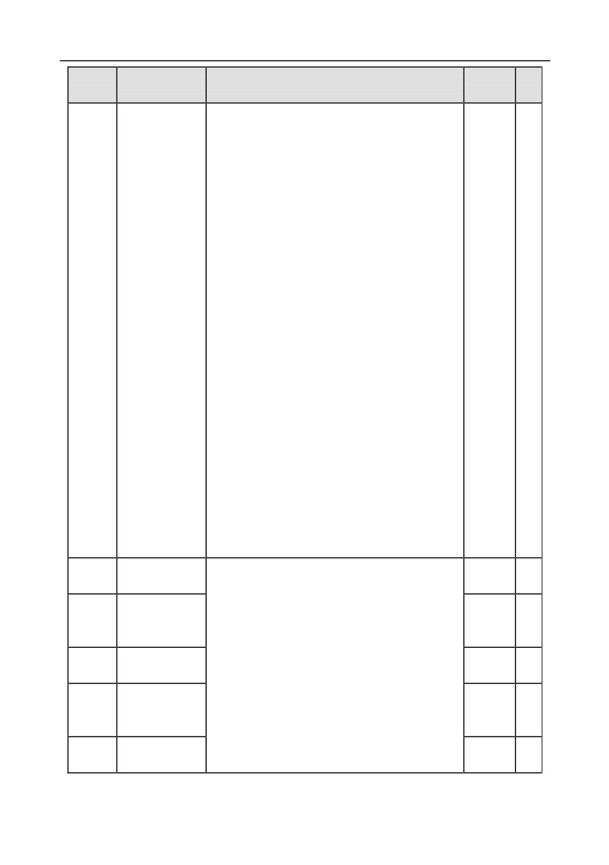
AO1 output
0: Running frequency
P06.14
0
○
selection
1: Set frequency
Reserved
2: Ramps reference frequency
P06.15
0
○
variables
3: Running speed
4: Output current (relative to inverter)
5: Output current (relative to motor)
HDO high-speed
P06.16
6: Output voltage
0
○
pulse output
7: Output power
8: Set torque value
-160-
Chapter 6
Function
Default
Modi
Name
Detailed parameter description
code
value
fy
9: Output torque
10: AI1 input value
11: AI2input value
12: AI3 input value
13: Input value of high-speed pulse HDIA
14: Set value 1 of MODBUS communication
15: Set value 2 of MODBUS communication
16: Set value 1 of PROFIBUS\CANopen
communication
17: Set value 2 of PROFIBUS\CANopen
communication
18: Set value 1 of Ethernet communication
19: Set value 2 of Ethernet communication
20: Input value of high-speed pulse HDIB
21: Reserved
22: Torque current (bipolar, 100% corresponds to
10V)
23: Exciting current (100% corresponds to 10V)
24: Set frequency (bipolar)
25: Ramps reference frequency (bipolar)
26: Running speed (bipolar)
27: Set value 2 of EtherCat/Profinet communication
28: C_AO1 from CODESYS (set P27.00 to 1)
29: C_AO2 from CODESYS (set P27.00 to 1)
30: Running speed
31-47: Reserved
Lower limit of
P06.17
0.0%
○
AO1 output
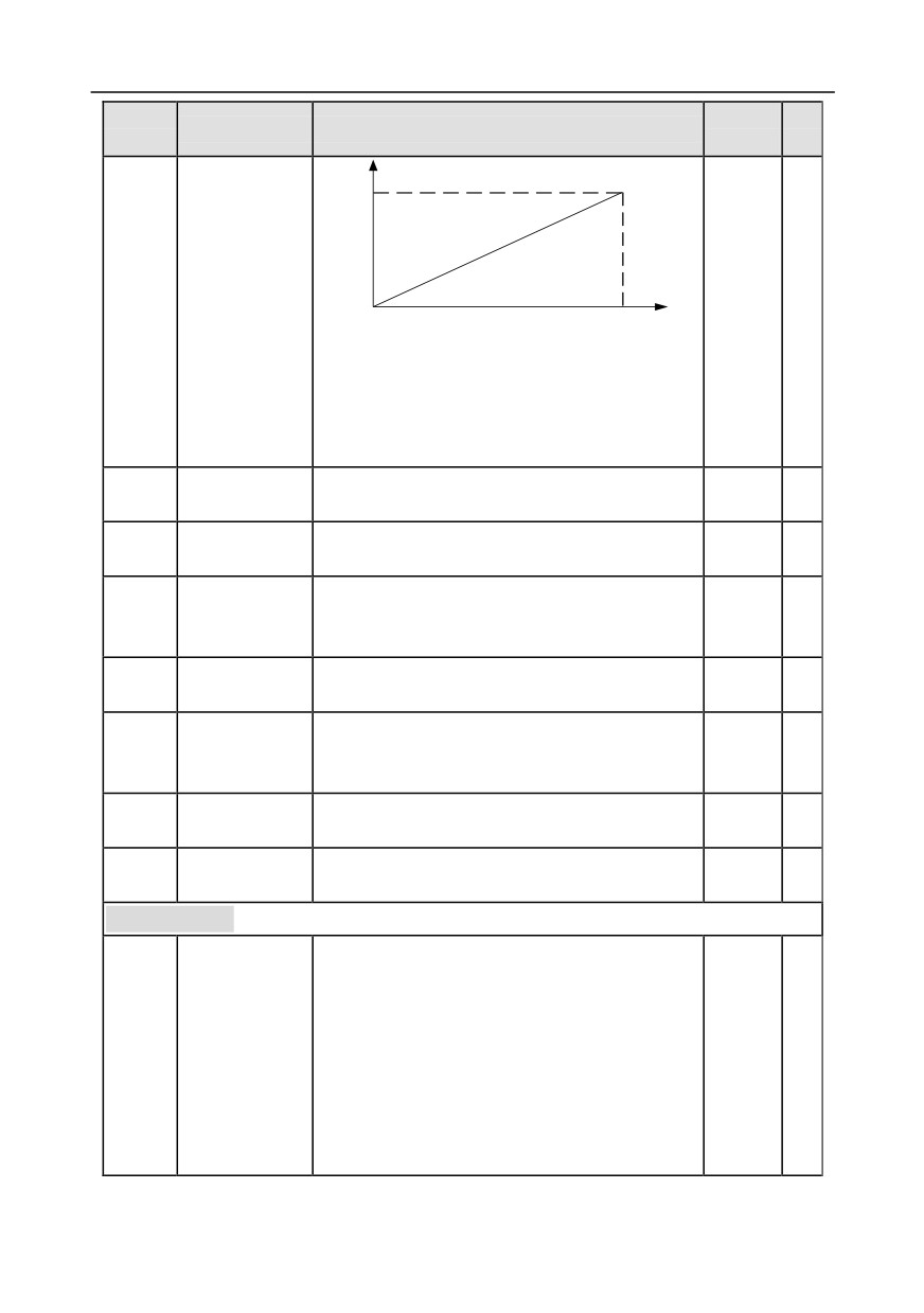
Above function codes define the relation between
Corresponding
output value and analog output. When the output
P06.18
AO1 output of
0.00V
○
value exceeds the set max./min. output range, the
lower limit
upper/low limit of output will be adopted during
Upper limit of
P06.19
calculation.
100.0%
○
AO1 output
When analog output is current output, 1mA
Corresponding
corresponds to 0.5V voltage. In different
P06.20
AO1 output of
10.00V
○
applications, 100% of output value corresponds to
upper limit
different analog outputs.
AO1 output filter
P06.21
0.000s
○
time
-161-
Chapter 6
Function
Default
Modi
Name
Detailed parameter description
code
value
fy
10V (20mA)
AO
0.0%
100.0%
Setting range of P06.17: -100.0%-P06.19
Setting range of P06.18: 0.00V-10.00V
Setting range of P06.19: P06.17-100.0%
Setting range of P06.20: 0.00V-10.00V
Setting range of P06.21: 0.000s-10.000s
P06.22-
Reserved
0-65535
0
●
P06.26
variables
Lower limit of
P06.27
-100.0%-P06.29
0.00%
○
HDO output
Corresponding
P06.28
HDO output of
0.00-50.00kHz
0.00kHz
○
lower limit
Upper limit of
P06.29
P06.27-100.0%
100.0%
○
HDO output
Corresponding
50.00
P06.30
HDO output of
0.00-50.00kHz
○
kHz
upper limit
HDO output filter
P06.31
0.000s-10.000s
0.000s
○
time
P06.32-
Reserved
0-65535
0
●
P06.34
variable
P07 group HMI
0-65535
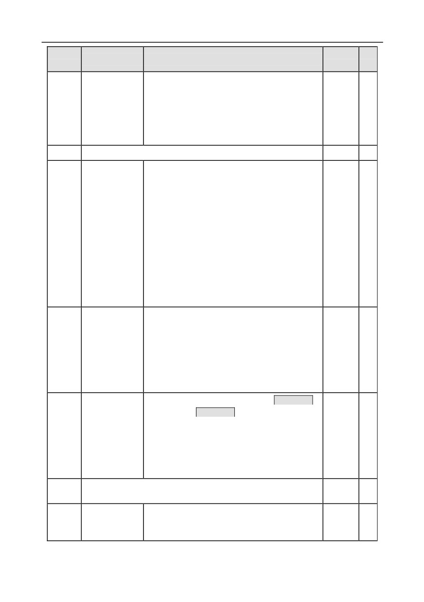
Set it to any non-zero value to
enable password
protection.
00000: Clear previous user password and disable
P07.00
User password
password protection.
0
○
After user password becomes valid, if wrong
password is inputted, users will be denied entry. It is
necessary to keep the user password in mind.
Password protection will be effective one minute
-162-
Chapter 6
Function
Default
Modi
Name
Detailed parameter description
code
value
fy
after exiting function code edit state, and it will
display "0.0.0.0.0" if users press PRG/ESC key to
enter function code edit state again, users need to
input the correct password.
Note: Restoring to default values will clear user
password, use this function with caution.
P07.01
Reserved variables
/
/
Range: 0x00-0x27
Ones: Function selection of QUICK/JOG key
0: No function
1: Jogging
2: Reserved
3: Forward/reverse rotation switch-over
P07.02
Function of keys
0x01
◎
4: Clear UP/DOWN setting
5: Coast to stop
6: Switch over the running command reference
mode in sequence
7: Reserved
Tens: Reserved
When P07.02=6, set the switch-over sequence of
Running
running command channel.
command
0: keypad control→terminal control→
channel
P07.03
communication control
0
○
switch-over
1: keypad control←→terminal control
sequence of
2: keypad control←→communication control
QUICK key
3: terminal control←→communication control
Validness selection of stop function of STOP/RST.
For fault reset, STOP/RST is valid under any
Stop function
situation.
P07.04
selection of
0: valid only for panel control only
0
○
STOP/RST key
1: valid for both panel and terminal control
2: valid for both panel and communication control
3: valid for all control modes
P07.05-
Reserved variables
/
/
P07.07
Frequency
0.01-10.00
P07.08
display
1.00
○
Display frequency=running frequency× P07.08
coefficient
-163-
Chapter 6
Function
Default
Modi
Name
Detailed parameter description
code
value
fy
0.1-999.9%
Speed display
P07.09
Mechanical speed=120×display running
100.0%
○
coefficient
frequency×P07.09/number of motor pole pairs
Linear speed
0.1-999.9%
P07.10
display
1.0%
○
Linear speed=mechanical speed×P07.10
coefficient
Temperature of
P07.11
rectifier bridge
-20.0-120.0°C
/
●
module
Temperature of
P07.12
-20.0-120.0°C
/
●
inverter module
Software version
P07.13
1.00-655.35
/
●
of control board
Accumulated
P07.14
0-65535h
/
●
running time
High bit of
P07.15
inverter power
Display the power consumption of the inverter.
/
●
consumption
Inverter power consumption=P07.15×1000+P07.16
Low bit of inverter
Setting range of P07.15: 0-65535 kWh (×1000)
P07.16
power
Setting range of P07.16: 0.0-999.9 kWh
/
●
consumption
P07.17
Reserved
/
/
Rated power of
P07.18
0.4-3000.0kW
/
●
inverter
Rated voltage of
P07.19
50-1200V
/
●
inverter
Rated current of
P07.20
0.1-6000.0A
/
●
inverter
P07.21
Factory barcode 1 0x0000-0xFFFF
/
●
P07.22
Factory barcode 2 0x0000-0xFFFF
/
●
P07.23
Factory barcode 3 0x0000-0xFFFF
/
●
P07.24
Factory barcode 4 0x0000-0xFFFF
/
●
P07.25
Factory barcode 5 0x0000-0xFFFF
/
●
P07.26
Factory barcode 6 0x0000-0xFFFF
/
●
Type of present
0: No fault
P07.27
/
●
fault
1: Inverter unit U phase protection (OUt1)
P07.28
Type of the last
2: Inverter unit V phase protection (OUt2)
/
●
-164-
Chapter 6
Function
Default
Modi
Name
Detailed parameter description
code
value
fy
fault
3: Inverter unit W phase protection (OUt3)
Type of the last
4: Overcurrent during acceleration (OC1)
P07.29
/
●
but one fault
5: Overcurrent during deceleration (OC2)
Type of the last
6: Overcurrent during constant speed (OC3)
P07.30
/
●
but two fault
7: Overvoltage during acceleration (OV1)
Type of the last
8: Overvoltage during deceleration (OV2)
P07.31
/
●
but three fault
9: Overvoltage during constant speed (OV3)
10: Bus undervoltage fault (UV)
11: Motor overload (OL1)
12: Inverter overload (OL2)
13: Phase loss on input side (SPI)
14: Phase loss on output side (SPO)
15: Rectifier module overheat (OH1)
16: Inverter module overheat (OH2)
17: External fault (EF)
18: 485 communication fault (CE)
19: Current detection fault (ItE)
20: Motor autotuning fault (tE)
21: EEPROM operation fault (EEP)
22: PID feedback offline fault (PIDE)
23: Brake unit fault (bCE)
24: Running time reached (END)
Type of the last
25: Electronic overload (OL3)
P07.32
/
●
but four fault
26: Keypad communication error (PCE)
27: Parameter upload error (UPE)
28: Parameter download error
(DNE)
29: Profibus communication fault (E-DP)
30: Ethernet communication fault (E-NET)
31: CANopen communication fault (E-CAN)
32: To-ground short-circuit fault 1 (ETH1)
33: To-ground short-circuit fault 2 (ETH2)
34: Speed deviation fault (dEu)
35: Mal-adjustment fault (STo)
36: Underload fault (LL)
37: Encoder offline fault (ENC1O)
38: Encoder reversal fault (ENC1D)
39: Encoder Z pulse offline fault (ENC1Z)
40: Safe torque off (STO)
41: Channel H1 safety circuit exception (STL1)
-165-
Chapter 6
Function
Default
Modi
Name
Detailed parameter description
code
value
fy
42: Channel H2 safety circuit exception (STL2)
43: Channel H1 and H2 exception (STL3)
44: Safety code FLASH CRC fault (CrCE)
45: PLC card customized fault 1 (P-E1)
46: PLC card customized fault 2 (P-E2)
47: PLC card customized fault 3 (P-E3)
48: PLC card customized fault 4 (P-E4)
49: PLC card customized fault 5 (P-E5)
50: PLC card customized fault 6 (P-E6)
51: PLC card customized fault 7 (P-E7)
52: PLC card customized fault 8 (P-E8)
53: PLC card customized fault 9 (P-E9)
54: PLC card customized fault 10 (P-E10)
55: Repetitive extension card type fault (E-Err)
56: Encoder UVW loss fault
(ENCUV)
57: Profibus communication fault (E-PN)
58: CANopen communication fault (ESCAN)
59: Motor over-temperature fault (OT)
60: Card slot 1 card identification failure (F1-Er)
61: Card slot 2 card identification failure (F2-Er)
62: Card slot 3 card identification failure (F3-Er)
63: Card slot 1 card communication timeout fault
(C1-Er)
64: Card slot 2 card communication timeout fault
(C2-Er)
65: Card slot 3 card communication timeout fault
(C3-Er)
66: EtherCat communication fault (E-CAT)
67: Bacnet communication fault (E-BAC)
68: DeviceNet communication fault (E-DEV)
69: Master-slave synchronous CAN slave fault
(S-Err)
P07.33
Running frequency of present fault
0.00Hz
●
P07.34
Ramps reference frequency of present fault
0.00Hz
●
P07.35
Output voltage of present fault
0V
●
P07.36
Output current of present fault
0.0A
●
P07.37
Bus voltage of present fault
0.0V
●
P07.38
Max. temperature of present fault
0.0°C
●
-166-
Chapter 6
Function
Default
Modi
Name
Detailed parameter description
code
value
fy
P07.39
Input terminal state of present fault
0
●
P07.40
Output terminal state of present fault
0
●
P07.41
Running frequency of the last fault
0.00Hz
●
P07.42
Ramps reference frequency of the last fault
0.00Hz
●
P07.43
Output voltage of the last fault
0V
●
P07.44
Output current of the last fault
0.0A
●
P07.45
Bus voltage of the last fault
0.0V
●
P07.46
Max. temperature of the last fault
0.0°C
●
P07.47
Input terminal state of the last fault
0
●
P07.48
Output terminal state of the last fault
0
●
P07.49
Running frequency of the last but one fault
0.00Hz
●
P07.50
Ramps reference frequency of the last but one fault
0.00Hz
●
P07.51
Output voltage of the last but one fault
0V
●
P07.52
Output current of the last but one fault
0.0A
●
P07.53
Bus voltage of the last but one fault
0.0V
●
P07.54
Max. temperature of the last but one fault
0.0°C
●
P07.55
Input terminal state of the last but one fault
0
●
P07.56
Output terminal state of the last but one fault
0
●
P08 group Enhanced functions
Acceleration
Depend
P08.00
○
time 2
on model
Deceleration
Depend
P08.01
See P00.11 and P00.12 for detailed definitions.
○
time 2
on model
Goodrive350 series inverter defines four groups of
Acceleration
Depend
P08.02
acceleration/deceleration time, which can be
○
time 3
on model
selected by multi-function digital input terminal (P05
Deceleration
Depend
P08.03
group). The acceleration/deceleration time of the
○
time 3
on model
inverter is the first group by default.
Acceleration
Depend
P08.04
Setting range: 0.0-3600.0s
○
time 4
on model
Deceleration
Depend
P08.05
○
time 4
on model
This function code is used to define the reference
Running
frequency of the inverter during jogging.
P08.06
frequency of
5.00Hz
○
Setting range: 0.00Hz-P00.03 (max. output
jogging
frequency)
-167-
Chapter 6
Function
Default
Modi
Name
Detailed parameter description
code
value
fy
Jogging acceleration time is the time needed for the
Acceleration time
P08.07
inverter to accelerate from
0Hz to max. output
○
of jogging
frequency (P00.03).
Depend
Jogging deceleration time is the time needed from
on model
Deceleration time
decelerating from the max. output frequency
P08.08
○
of jogging
(P00.03) to 0Hz.
Setting range: 0.0-3600.0s
P08.09
Jump frequency 1
When the set frequency is within the range of jump
0.00Hz
○
frequency, the inverter will run at the boundary of
Jump frequency
P08.10
0.00Hz
○
jump frequency.
amplitude 1
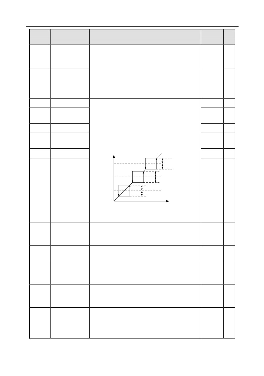
The inverter can avoid mechanical resonance point
P08.11
Jump frequency 2
0.00Hz
○
by setting the jump frequency, and three jump
Jump frequency
P08.12
frequency points can be set. If the jump frequency
0.00Hz
○
amplitude 2
points are set to 0, this function will be invalid.
P08.13
Jump frequency 3
0.00Hz
○
Set frequency f
1/2* jump amplitude 3
Jump
frequency 3
1/2* jump amplitude 3
1/2* jump amplitude 2
Jump
frequency 2
1/2* jump amplitude 2
Jump frequency
1/2* jump amplitude 1
P08.14
Jump
0.00Hz
○
frequency 1
1/2* jump amplitude 1
amplitude 3
Time t
Setting range: 0.00Hz-P00.03 (max. output
frequency)
Amplitude of
○
P08.15
wobbling
0.0-100.0% (relative to set frequency)
0.0%
frequency
Amplitude of
0.0-50.0% (relative to amplitude of wobbling
○
P08.16
0.0%
jump frequency
frequency)
Rise time of
○
P08.17
wobbling
0.1-3600.0s
5.0s
frequency
Descend time of
○
P08.18
wobbling
0.1-3600.0s
5.0s
frequency
Switching
0.00-P00.03 (max. output frequency)
frequency of
0.00Hz: no switch-over
P08.19
0.00Hz
○
acceleration/dec
Switch to acceleration/deceleration time
2
if the
eleration time
running frequency is larger than P08.19
-168-
Chapter 6
Function
Default
Modi
Name
Detailed parameter description
code
value
fy
Frequency
threshold of the
P08.20
0.00-50.00Hz
2.00Hz
○
start of droop
control
0: Max. output frequency
Reference
1: Set frequency
frequency of
P08.21
2: 100Hz
0
◎
acceleration/dec
Note: Valid for straight acceleration/deceleration
eleration time
only
Reserved
P08.22
0-65535
0
○
variables
Number of
0: Two decimal points
P08.23
decimal points of
0
○
1: One decimal point
frequency
0: No decimal point
Number of
1: One
P08.24
decimal points of
0
○
2: Two
linear speed
3: Three
P08.25
Set count value
P08.26-65535
0
○
Designated count
P08.26
0-P08.25
0
○
value
P08.27
Set running time
0-65535min
0min
○
Automatic fault
Automatic fault reset times: When the inverter
P08.28
0
○
reset times
selects automatic fault reset, it is used to set the
times of automatic reset, if the continuous reset
times exceeds the value set by P08.29, the inverter
will report fault and stop to wait for repair.
Interval of automatic fault reset: select the interval
Automatic fault
time from when fault occurred to automatic fault
P08.29
reset time
1.0s
○
reset actions.
interval
After inverter starts, if no fault occurred during 60s,
the fault reset times will be zeroed out.
Setting range of P08.28: 0-10
Setting range of P08.29: 0.1-3600.0s
This function code sets the variation rate of the
Reduction ratio of
inverter output frequency based on the load; it is
P08.30
0.00Hz
○
droop control
mainly used in balancing the power when multiple
motors drive the same load.
-169-
Chapter 6
Function
Default
Modi
Name
Detailed parameter description
code
value
fy
Setting range: 0.00-50.00Hz
0x00-0x14
Ones: Switch-over channel
0: Switch over by terminal
1: Switch over by MODBUS communication
Switch-over
2: Switch over by PROFIBUS/CANopen/DeviceNet
P08.31
between motor 1
0x00
◎
3: Switch over by Ethernet communication
and motor 2
4: Switch over by EtherCat/Profinet communication
Tens: Motor switch over during running
0: Disable switch over during running
1: Enable switch over during running
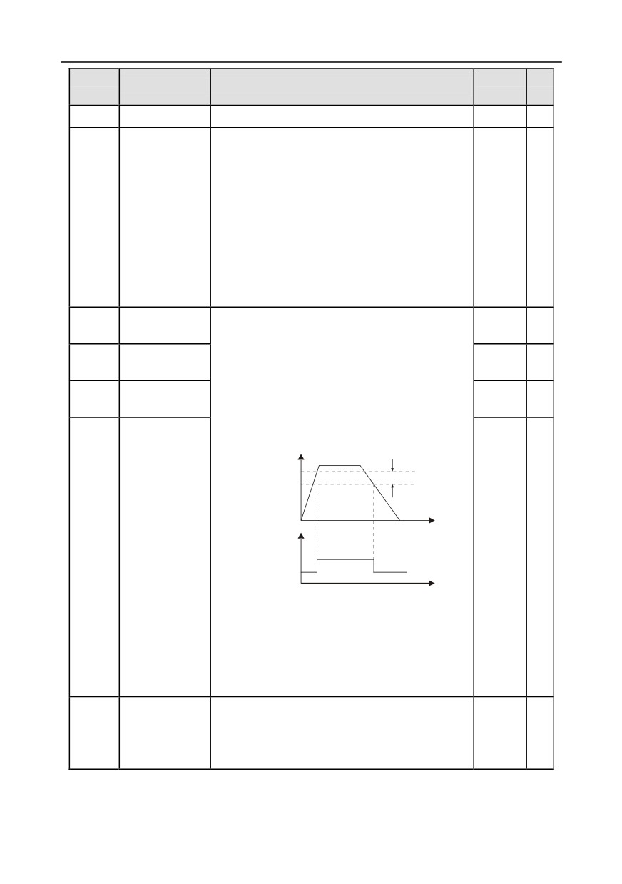
FDT1 level
When the output frequency exceeds the
P08.32
50.00Hz
○
detection value
corresponding frequency of FDT level, multi-function
FDT1 lag
digital output terminal outputs "frequency level
P08.33
5.0%
○
detection value
detection FDT" signal, this signal will be valid until
FDT2 level
the output frequency lowers to below the
P08.34
50.00Hz
○
detection value
corresponding frequency (FDT level-FDT lag
detection value), the waveform is shown in the figure
below.
Output frequency f
FDT level
FDT lag
Time t
FDT2 lag
P08.35
Y1,
5.0%
○
detection value
RO1, RO2
Time t
Setting range of P08.32: 0.00Hz-P00.03 (max.
output frequency)
Setting range of P08.33: 0.0-100.0% (FDT1 level)
Setting range of P08.34: 0.00Hz-P00.03 (max.
output frequency)
Setting range of P08.35: 0.0-100.0% (FDT2 level)
When the output frequency is within the positive
Detection value
/negative detection range of the set frequency, the
P08.36
for frequency
0.00Hz
○
multi-function digital output terminal outputs
arrival
"frequency arrival" signal as shown below.
-170-

Chapter 6
Function
Default
Modi
Name
Detailed parameter description
code
value
fy
Output frequency
Set
Detection amplitude
frequency
Time t
Y,
RO1, RO2
Time t
Setting range: 0.00Hz-P00.03 (max. output
frequency)
Enable/disable
energy-
0: Disable energy-consumption
P08.37
1
○
consumption
1: Enable energy-consumption
brake
220V
voltage:
Set the starting bus voltage of energy-consumption
380.0V;
Energy-
brake, adjust this value properly can brake the load
380V
consumption
P08.38
effectively. The default value will change with the
voltage:
○
brake threshold
change of voltage class.
700.0V;
voltage
Setting range: 200.0-2000.0V
660V
voltage:
1120.0V
Running mode of
0: Common running mode
P08.39
0
○
cooling fan
1: The fan keeps running after power up
0x0000-0x1121
Ones: PWM mode
0: 3PH modulation and 2-phase modulation
1: 3PH modulation
Tens: PWM low-speed carrier limit
0: Limit low-speed carrier to 2K
P08.40
PWM selection
0001
◎
1: Limit low-speed carrier to 4K
2: No limit on low-speed carrier
Hundreds: Reserved
Thousands: PWM loading mode
0: PWM loading mode 1
1: PWM loading mode 2
-171-
Chapter 6
Function
Default
Modi
Name
Detailed parameter description
code
value
fy
0x00-0x11
Ones
0: Overmodulation is invalid
Overmodulation
P08.41
1: Overmodulation is valid
01
◎
selection
Tens
0: Mild overmodulation
1: Deepened overmodulation
P08.42
Reserved variables
/
/
P08.43
Reserved variables
/
/
0x000-0x221
Ones: Frequency control selection
0: UP/DOWN terminal setup is valid
1: UP/DOWN terminal setup is invalid
Tens: Frequency control selection
0: Valid only when P00.06=0 or P00.07=0
UP/DOWN
1: All frequency modes are valid
P08.44
terminal control
0x000
○
2: Invalid for multi-step speed when multi-step speed
setup
takes priority
Hundreds: Action selection during stop
0: Valid
1: Valid during running, clear after stop
2: Valid during running, clear after receiving stop
command
UP terminal
frequency
P08.45
0.01-50.00Hz/s
0.50Hz/s
○
incremental
integral rate
DOWN terminal
frequency
P08.46
0.01-50.00Hz/s
0.50Hz/s
○
decremental
change rate
0x000-0x111
Ones: Action selection for frequency setup
(by
Action selection
keypad digits) during power down
for frequency
P08.47
0: Save during power down
0x000
○
setup during
1: Zero out during power down
power down
Tens: Action selection for frequency setup (by
MODBUS) during power down
-172-
Chapter 6
Function
Default
Modi
Name
Detailed parameter description
code
value
fy
0: Save during power down
1: Zero out during power down
Hundreds: Action selection for frequency setup (by
other communication) during power down
0: Save during power down
1: Zero out during power down
High bit of initial
Set the initial value of power consumption.
P08.48
value of power
0°
○
Initial value of power consumption=P08.48×1000+
consumption
P08.49
Low bit of initial
Setting range of P08.48: 0-59999 kWh (k)
P08.49
value of power
0.0°
○
Setting range of P08.49: 0.0-999.9 kWh
consumption
This function code is used to enable flux braking
function.
0: Invalid
100-150: The larger the coefficient, the stronger the
brake intensity
The inverter enables motor to decelerate quickly by
increasing the motor flux which converts energy
generated during braking into thermal energy.
The inverter monitors motor state continuously even
P08.50
Flux braking
0
○
during flux braking, thus flux braking can be applied
in motor stop or used to change motor speed. The
flux braking also carries the following advantages.
1) Brake immediately after sending stop command,
removing the need to wait for flux to attenuate.
2) Better cooling effect. During flux braking, the
stator current of the motor increases, while the rotor
current does not change, while the cooling effect of
stator is much more effective than that of the rotor.
Current
This function code is used to adjust the current
regulation
P08.51
display value on the AC input side.
0.56
○
coefficient on
0.00-1.00
input side
0: STO alarm lock
Alarm-lock means STO alarm must be reset after
P08.52
STO lock
state restoration when STO occurs.
0
○
1: STO alarm unlock
Alarm-unlock means when STO occurs, after state
-173-
Chapter 6
Function
Default
Modi
Name
Detailed parameter description
code
value
fy
restoration, STO alarm will disappear automatically.
Bias value of
upper limit
P08.53
0.00 Hz-P00.03 (max. output frequency)
0.00Hz
○
frequency of
torque control
Acceleration/dec
0: No limit on acceleration or deceleration
eleration
1: Acceleration/deceleration time 1
selection of
P08.54
2: Acceleration/deceleration time 2
0
○
upper limit
3: Acceleration/deceleration time 3
frequency of
4: Acceleration/deceleration time 4
torque control
P09 group PID control
When frequency command (P00.06, P00. 07) is set
to 7, or channel of voltage setup (P04.27) is set to 6,
the inverter running mode is process PID control.
This parameter determines the target reference
channel of process PID.
0: Keypad (P09.01)
1: AI1
2: AI2
3: AI3
4: High-speed pulse HDIA
5: Multi-step
PID reference
P09.00
6: MODBUS communication
0
○
source
7: PROFIBUS/CANopen/DeviceNet communication
8: Ethernet communication
9: High-speed pulse HDIB
10: EtherCat/Profinet communication
11: Programmable extension card
12: Reserved
The set target value of process PID is relative value,
the set 100% corresponds to 100% of the feedback
signal of controlled system.
The system operates based on the relative value (0-
100.0%)
Pre-set PID
Users need to set this parameter when P09.00 is set
P09.01
reference of
to 0, the reference value of this parameter is the
0.0%
○
keypad
feedback variable of the system.
-174-
Chapter 6
Function
Default
Modi
Name
Detailed parameter description
code
value
fy
Setting range: -100.0%-100.0%
This parameter is used to select PID feedback
channel.
0: AI1
1: AI2
2: AI3
3: High-speed pulse HDIA
4: MODBUS communication
PID feedback
5: PROFIBUS/CANopen/DeviceNet communication
P09.02
0
○
source
6: Ethernet communication
7: High-speed pulse HDIB
8: EtherCat/Profinet communication
9: Programmable extension card
10: Reserved
Note: The reference channel and feedback
channel cannot overlap; otherwise, PID cannot
be controlled effectively.
0: PID output is positive characteristic: namely, the
feedback signal is larger than the PID reference,
which requires the inverter output frequency to
decrease for PID to reach balance, eg, tension PID
PID output
control of winding
P09.03
0
○
characteristics
1: PID output is negative characteristics: namely the
feedback signal is less than PID reference, which
requires inverter output frequency to increase for
PID to reach balance, eg, tension PID control of
unwinding.
This function code is suitable for proportional gain P
of PID input.
It determines the regulation intensity of the whole
PID regulator, the larger the value of P, the stronger
the regulation intensity. If this parameter is 100, it
Proportional gain
P09.04
means when the deviation between PID feedback
1.80
○
(Kp)
and reference is 100%, the regulation amplitude of
PID regulator (ignoring integral and differential
effect) on output frequency command is the max.
frequency (ignoring integral and differential actions).
Setting range: 0.00-100.00
-175-
Chapter 6
Function
Default
Modi
Name
Detailed parameter description
code
value
fy
It determines the speed of integral regulation made
0.90s
on the deviation between PID feedback and
reference by PID regulator. When the deviation
between PID feedback and reference is 100%, the
regulation of integral regulator (ignoring integral and
P09.05
Integral time (Ti)
differential actions), after undergoing continuous
○
regulation during this time period, can reach the
max. output frequency (P00.03)
The shorter the integral time, the stronger the
regulation intensity.
Setting range: 0.00-10.00s
It determines the intensity of the regulation made on
the change rate of deviation between PID feedback
and reference by PID regulator. If feedback changes
by 100% during this period, the regulation of
Derivative time
P09.06
differential regulator (ignoring integral and differential
0.00s
○
(Td)
actions) is the max. output frequency (P00.03)
The longer the derivative time, the stronger the
regulation intensity.
Setting range: 0.00-10.00s
It means the sampling cycle of feedback. The
regulator operates once during each sampling cycle.
Sampling cycle
P09.07
The larger the sampling cycle, the slower the
0.001s
○
(T)
response.
Setting range: 0.001-10.000s
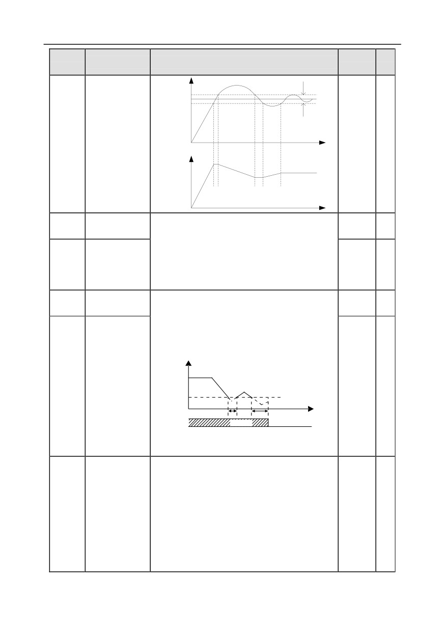
It is the max. allowable deviation of PID system
output value relative to closed-loop reference value.
Limit of PID
Within this limit, PID regulator stops regulation. Set
P09.08
0.0%
○
control deviation
this function code properly to regulate the precision
and stability of PID system.
Setting range: 0.0-100.0%
-176-
Chapter 6
Function
Default
Modi
Name
Detailed parameter description
code
value
fy
Deviation
Feedback
limit
Reference
Time t
Output
frequency f
Time t
Upper limit value
These two function codes are used to set the
P09.09
100.0%
○
of PID output
upper/lower limit value of PID regulator.
100.0% corresponds to max. output frequency
Lower limit value
(P00.03) or max. voltage (P04.31)
P09.10
0.0%
○
of PID output
Setting range of P09.09: P09.10-100.0%
Setting range of P09.10: -100.0%-P09.09
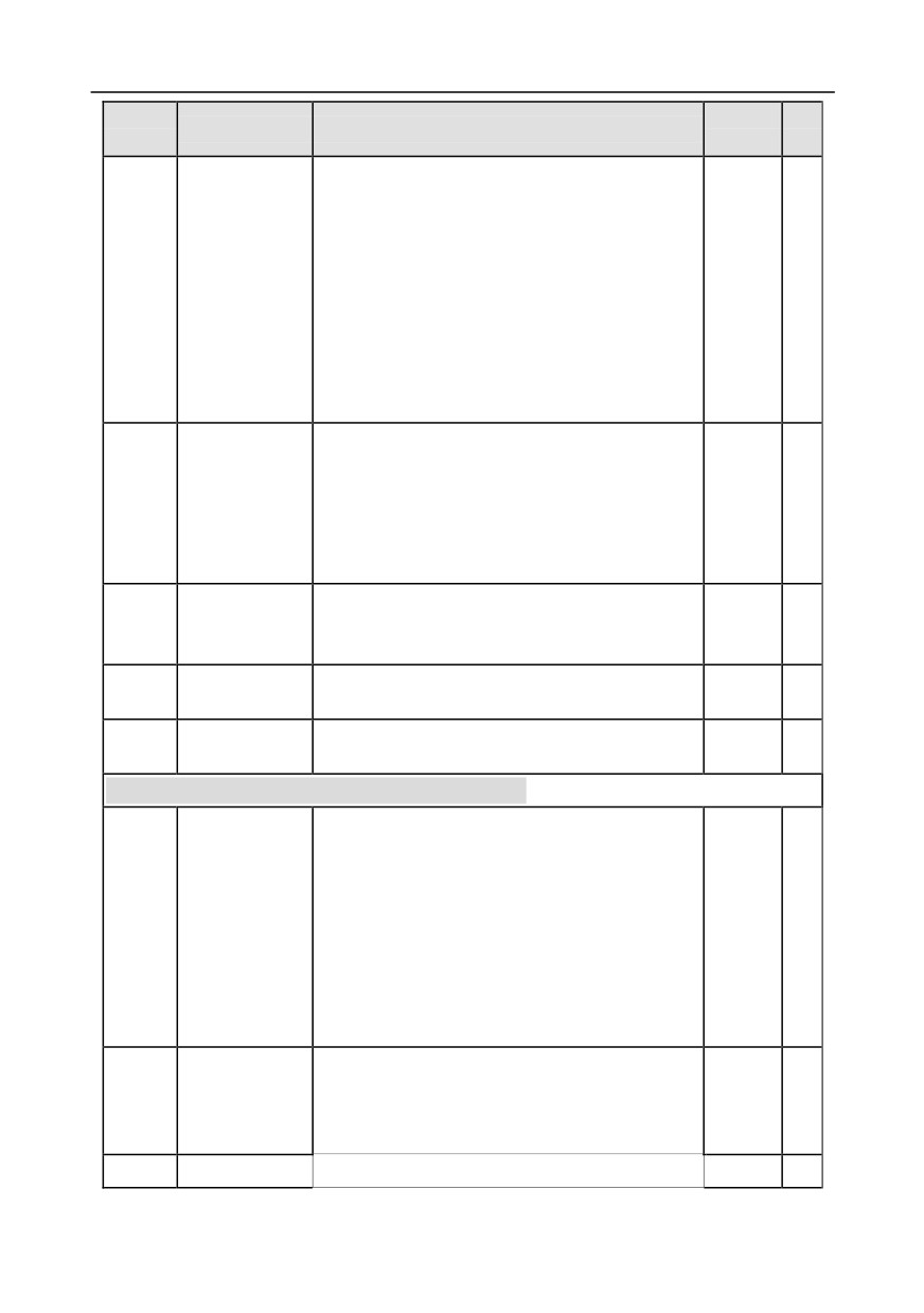
Feedback offline
Set PID feedback offline detection value, when the
P09.11
0.0%
○
detection value
detection value is no more than the feedback offline
detection value, and the duration exceeds the value
set in P09.12, the inverter will report "PID feedback
offline fault", and keypad displays PIDE.
Output frequency
t1<T2, so the inverter
continues running
t2=P09.12
Feedback offline
P09.12
1.0s
○
detection time
PIDE
P09.11
T
t1
t2
Running
Fault output PIDE
Setting range of P09.11: 0.0-100.0%
Setting range of P09.12: 0.0-3600.0s
0x0000-0x1111
Ones:
0: Continue integral control after the frequency
reaches upper/lower limit
PID control
P09.13
1: Stop integral control after the frequency reaches
0x0001
○
selection
upper/lower limit
Tens:
0: The same with the main reference direction
1: Contrary to the main reference direction
-177-
Chapter 6
Function
Default
Modi
Name
Detailed parameter description
code
value
fy
Hundreds:
0: Limit based on the max. frequency
1: Limit based on A frequency
Thousands:
0: A+B frequency, acceleration /deceleration of main
reference A frequency source buffering is invalid
1: A+B frequency, acceleration/ deceleration of main
reference A frequency source buffering is valid,
acceleration and deceleration are determined by
P08.04 (acceleration time 4).
0.00-100.00
Low-frequency
switching
point:
5.00Hz,
Low-frequency
high-frequency switching point:
10.00Hz
(P09.04
P09.14
proportional gain
1.00
○
corresponds to high-frequency parameter), and the
(Kp)
middle is the linear interpolation between these two
points
Acceleration/
P09.15
deceleration time
0.0-1000.0s
0.0s
○
of PID command
Filter time of PID
P09.16
0.000-10.000s
0.000s
○
output
P09.17-
Reserved
0-65536
0
○
P09.28
variables
P10 group Simple PLC and multi-step speed control
0: Stop after running once; the inverter stops
automatically after running for one cycle, and it can
be started only after receiving running command.
1: Keep running in the final value after running once;
Simple PLC
P10.00
The inverter keeps the running frequency and
0
○
mode
direction of the last section after a single cycle.
2: Cyclic running; the inverter enters the next cycle
after completing one cycle until receiving stop
command and stops.
0: No memory after power down
Simple PLC
1: Memory after power down; PLC memories its
P10.01
0
○
memory selection running stage and running frequency before power
down.
P10.02
Multi-step speed 0
Setting range of the frequency in 0th -15th sections
0.0%
○
-178-
Chapter 6
Function
Default
Modi
Name
Detailed parameter description
code
value
fy
Running time of
are
-100.0-100.0%,
100% corresponds to max.
P10.03
0.0s(min)
○
0th step
output frequency P00.03.
P10.04
Multi-step speed 1
Setting range of the running time in 0th -15th sections
0.0%
○
are 0.0-6553.5s (min), the time unit is determined by
Running time of
P10.05
P10.37.
0.0s(min)
○
1st step
When simple PLC operation is selected, it is required
P10.06
Multi-step speed 2
0.0%
○
to set P10.02-P10.33 to determine the running
Running time of
P10.07
frequency and running time of each section.
0.0s(min)
○
2nd step
Note: The symbol of multi-step speed
P10.08
Multi-step speed 3
0.0%
○
determines the running direction of simple PLC,
Running time of
and the negative value means reverse running.
P10.09
Deceleration time P10.28
0.0s(min)
○
3rd step
(two sections)
P10.04
P10.30
P10.10
Multi-step speed 4
0.0%
○
P10.02
P10.32
Running time of
P10.11
Acceleration time
0.0s(min)
○
4th step
(two sections)
P10.06
P10.12
Multi-step speed 5
0.0%
○
Running time of
P10.03
P10.05
P10.07
P10.31
P10.33
P10.13
0.0s(min)
○
5th step
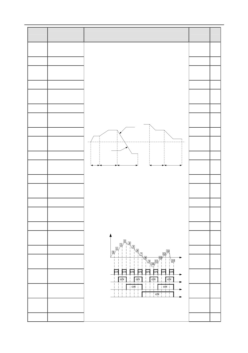
When selecting multi-step speed running, the
P10.14
Multi-step speed 6
multi-step speed is within the range of -fmax-fmax,
0.0%
○
Running time of
and it can be set continuously. The start/stop of
P10.15
0.0s(min)
○
6th step
multi-step stop is also determined by P00.01.
Goodrive350 series inverter can set 16-step speed,
P10.16
Multi-step speed 7
0.0%
○
which are set by combined codes of multi-step
Running time of
P10.17
terminals
1-4 (set by S terminal, correspond to
0.0s(min)
○
7th
step
function code P05.01-P05.06) and correspond to
P10.18
Multi-step speed 8
0.0%
○
multi-step speed 0 to multi-step speed 15.
Running time of
Output frequency
P10.19
0.0s(min)
○
8th step
P10.20
Multi-step speed 9
0.0%
○
t
Running time of
P10.21
0.0s(min)
○
9th step
t
Multi-step speed
Terminal 1
P10.22
0.0%
○
10
t
Terminal 2
Running time of
t
Terminal 3
P10.23
0.0s(min)
○
10th step
t
Terminal 4
Multi-step speed
P10.24
When terminal 1, terminal 2, terminal 3 and terminal
0.0%
○
11
4 are OFF, the frequency input mode is set by
P10.25
Running time of
0.0s(min)
○
-179-
Chapter 6
Function
Default
Modi
Name
Detailed parameter description
code
value
fy
11th step
P00.06 or P00.07. When terminal 1, terminal 2,
terminal
3 and terminal
4 are not all OFF, the
Multi-step speed
P10.26
0.0%
○
frequency set by multi-step speed will prevail, and
12
the priority of multi-step setting is higher than that of
Running time of
P10.27
the keypad, analog, high-speed pulse, PID, and
0.0s(min)
○
12th step
communication settings.
Multi-step speed
P10.28
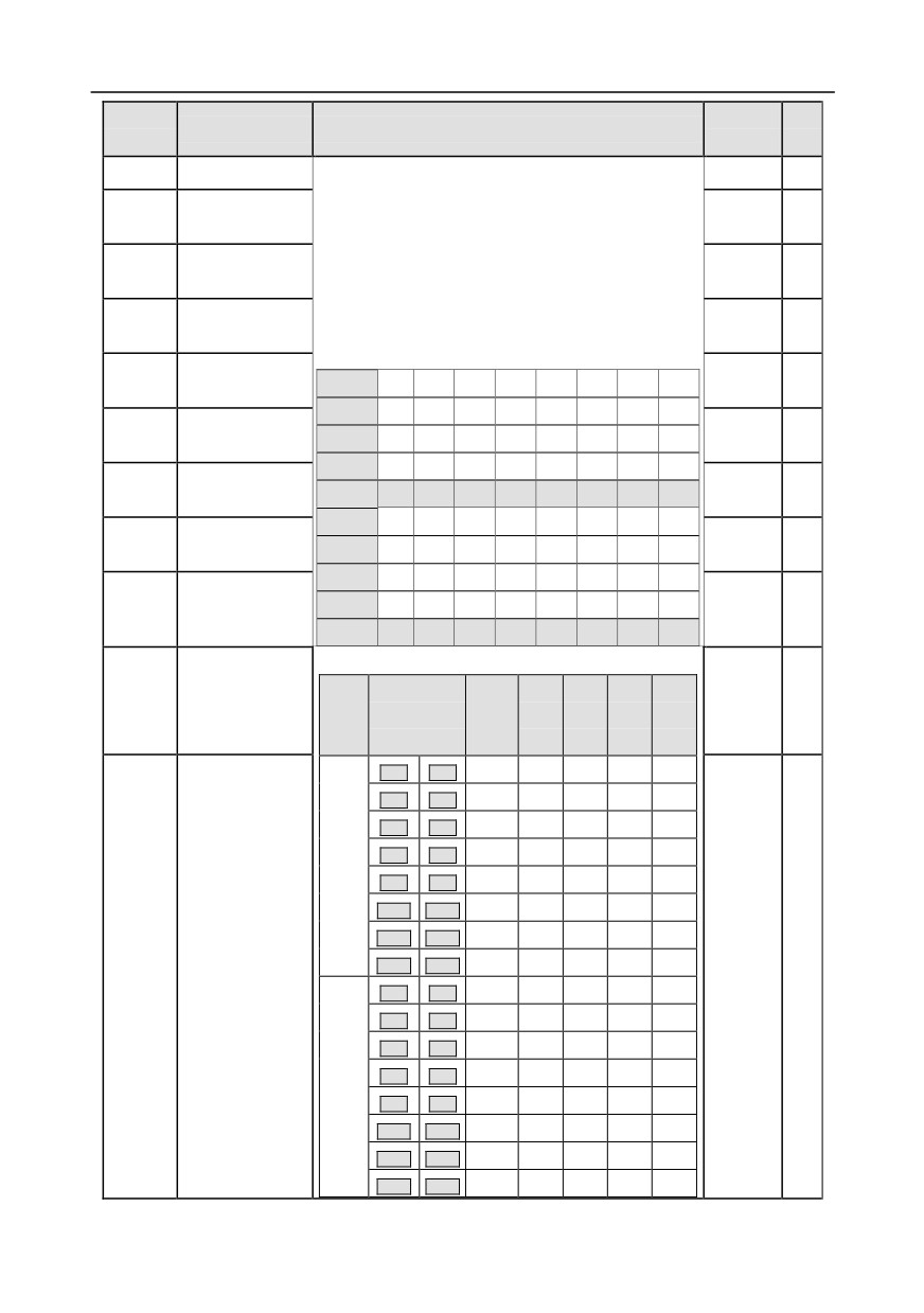
The relation between terminal 1, terminal 2, terminal
0.0%
○
13
3 and terminal 4 are shown in the table below.
Running time of
P10.29
Terminal 1
OFF
ON
OFF
ON
OFF
ON
OFF
ON
0.0s(min)
○
13th step
Terminal 2
OFF
OFF
ON
ON
OFF
OFF
ON
ON
Multi-step speed
P10.30
Terminal 3
OFF
OFF
OFF
OFF
ON
ON
ON
ON
0.0%
○
14
Terminal 4
OFF
OFF
OFF
OFF
OFF
OFF
OFF
OFF
Running time of
P10.31
Step
0
1
2
3
4
5
6
7
0.0s(min)
○
14th step
Terminal 1
OFF
ON
OFF
ON
OFF
ON
OFF
ON
Multi-step speed
P10.32
0.0%
○
Terminal 2
OFF
OFF
ON
ON
OFF
OFF
ON
ON
15
Terminal 3
OFF
OFF
OFF
OFF
ON
ON
ON
ON
Running time of
Terminal 4
ON
ON
ON
ON
ON
ON
ON
ON
P10.33
15th step
0.0s(min)
○
Step
8
9
10
11
12
13
14
15
Acceleration/dec
Detailed illustration is shown in the table below.
eleration time of
ACC/
ACC/
ACC/
ACC/
P10.34
Function
Step
0x0000
○
0th -7th step of
Binary
DEC
DEC
DEC
DEC
code
number
simple PLC
time 1
time 2
time 3
time 4
BIT1
BIT0
0
00
01
10
11
BIT3
BIT2
1
00
01
10
11
BIT5
BIT4
2
00
01
10
11
BIT7
BIT6
3
00
01
10
11
P10.34
BIT9
BIT8
4
00
01
10
11
BIT11
BIT10
5
00
01
10
11
Acceleration/dec
BIT13
BIT12
6
00
01
10
11
eleration time of
BIT15
BIT14
7
00
01
10
11
P10.35
0x0000
○
8th - 15th step of
BIT1
BIT0
8
00
01
10
11
simple PLC
BIT3
BIT2
9
00
01
10
11
BIT5
BIT4
10
00
01
10
11
BIT7
BIT6
11
00
01
10
11
P10.35
BIT9
BIT8
12
00
01
10
11
BIT11
BIT10
13
00
01
10
11
BIT13
BIT12
14
00
01
10
11
BIT15
BIT14
15
00
01
10
11
-180-
Chapter 6
Function
Default
Modi
Name
Detailed parameter description
code
value
fy
Select corresponding acceleration/deceleration time,
and then convert 16-bit binary number into
hexadecimal number, finally, set corresponding
function code.
Acceleration/deceleration time 1 is set by P00.11
and P00.12; Acceleration/deceleration time 2 is set
by P08.00 and P08.01; Acceleration/deceleration
time 3 is set by P08.02 and P08.03; Acceleration
/deceleration time 4 is set by P08.04 and P08.05.
Setting range: 0x0000-0xFFFF
0: Restart from the first step, namely if the inverter
stops during running (caused by stop command,
fault or power down), it will run from the first step
after restart.
1: Continue running from the step frequency when
P10.36
PLC restart mode interruption occurred, namely if the inverter stops
0
◎
during running (caused by stop command or fault),
it will record the running time of current step, and
enters this step automatically after restart, then
continue running at the frequency defined by this
step in the remaining time.
0: s; the running time of each step is counted in
Multi-step time
seconds;
P10.37
0
◎
unit
1: min; the running time of each step is counted in
minutes;
P11 group Protection parameters
0x000-0x111
Ones:
0: Disable software input phase loss protection
1: Enable software input phase loss protection
Phase-loss
Tens:
P11.00
0x110
○
protection
0: Disable output phase loss protection
1: Enable output phase loss protection
Hundreds:
0: Disable hardware input phase loss protection
1: Enable hardware input phase loss protection
Frequency-drop
0: Disable
P11.01
0
○
at transient
1: Enable
-181-
Chapter 6
Function
Default
Modi
Name
Detailed parameter description
code
value
fy
power down
Reserved
P11.02
0-65535
0
○
variables
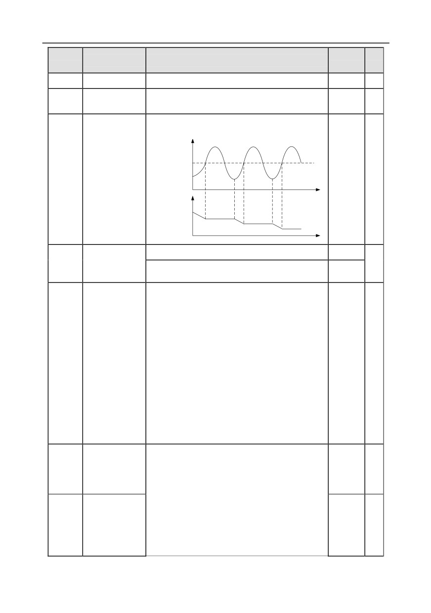
0: Disable
1: Enable
DC bus voltage V
Overvoltage stall
threshold
Overvoltage stall
P11.03
1
○
protection
Time t
Output
frequency
Time t
Overvoltage stall
120-150% (standard bus voltage) (380V)
136%
P11.04
protection
○
120-150% (standard bus voltage) (220V)
120%
voltage
During accelerated running, as the load is too large,
the actual acceleration rate of motor is lower than
that of output frequency, if no measures are taken,
the inverter may trip due to overcurrent during
acceleration.
0x00-0x11
Current-limit
P11.05
Ones: Current-limit action selection
01
◎
selection
0: Invalid
1: Always valid
Tens: Hardware current-limit overload alarm
selection
0: Valid
1: Invalid
Current-limit protection function detects output
G model:
Automatic
current during running, and compares it with the
160.0%
P11.06
◎
current-limit level
current-limit level defined by P11.06, if it exceeds the
P model:
current-limit level, the inverter will run at stable
120.0%
frequency during accelerated running, or run in
Frequency-drop
decreased frequency during constant-speed
10.00
P11.07
rate during
running; if it exceeds the current-limit level
◎
Hz/s
current limit
continuously, the inverter output frequency will drop
continuously until reaching lower limit frequency.
-182-
Chapter 6
Function
Default
Modi
Name
Detailed parameter description
code
value
fy
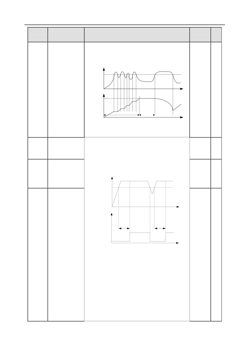
When the output current is detected to be lower than
the current-limit level again, it will continue
accelerated running.
Output current A
Current-limit
threshold
Output frequency f
Time t
Set
frequency
Constant
Acceleration
speed
Time t
Setting range of P11.06: 50.0-200.0%
Setting range of P11.07: 0.00-50.00Hz/s
Inverter or motor
If the inverter or motor output current is larger than
P11.08
overload/underlo
the overload pre-alarm detection level (P11.09), and
0x000
○
ad pre-alarm
the duration exceeds the overload pre-alarm
detection time (P11.10), overload pre-alarm signal
G model:
Overload
will be outputted.
150%
P11.09
pre-alarm
Output current
○
P model:
detection level
Overload pre-alarm
120%
threshold
Time t
Pre-alarm time t
Pre-alarm time t
Y,
RO1, RO2
Time t
Overload
P11.10
pre-alarm
Setting range of P11.08:
1.0s
○
detection time
Enable and define overload pre-alarm function of the
inverter and motor
Setting range: 0x000-0x131
Ones:
0: Motor overload/underload pre-alarm, relative to
rated motor current;
1: Inverter overload/underload pre-alarm, relative to
rated inverter current.
Tens:
-183-
Chapter 6
Function
Default
Modi
Name
Detailed parameter description
code
value
fy
0: The inverter continues running after
overload/underload alarm;
1: The inverter continues running after underload
alarm, and stops running after overload fault;
2: The inverter continues running after overload
alarm, and stops running after underload fault;
3: The inverter stops running after overload/underload
fault.
Hundreds:
0: Always detect
1: Detect during constant-speed running
Setting range of P11.09: P11.11-200%
Setting range of P11.10: 0.1-3600.0s
Underload
Underload pre-alarm signal will be outputted if the
P11.11
pre-alarm
output current of the inverter or motor is lower than
50%
○
detection level
underload pre-alarm detection level (P11.11), and
the duration exceeds underload pre-alarm detection
Underload
time (P11.12).
P11.12
pre-alarm
1.0s
○
Setting range of P11.11: 0- P11.09
detection time
Setting range of P11.12: 0.1-3600.0s
This function code is used to set the action of fault
output terminals during undervoltage and fault reset.
0x00-0x11
Fault output
Ones:
P11.13
terminal action
0: Act during undervoltage fault
0x00
○
during fault
1: Do not act during undervoltage fault
Tens:
0: Act during fault reset
1: Do not act during fault reset
0.0-50.0%
Speed deviation
P11.14
This parameter is used to set the speed deviation
10.0%
○
detection value
detection value.
This parameter is used to set the speed deviation
Speed deviation
detection time.
P11.15
1.0s
○
detection time
Note: Speed deviation protection will be invalid if
P11.15 is set to 0.0.
-184-
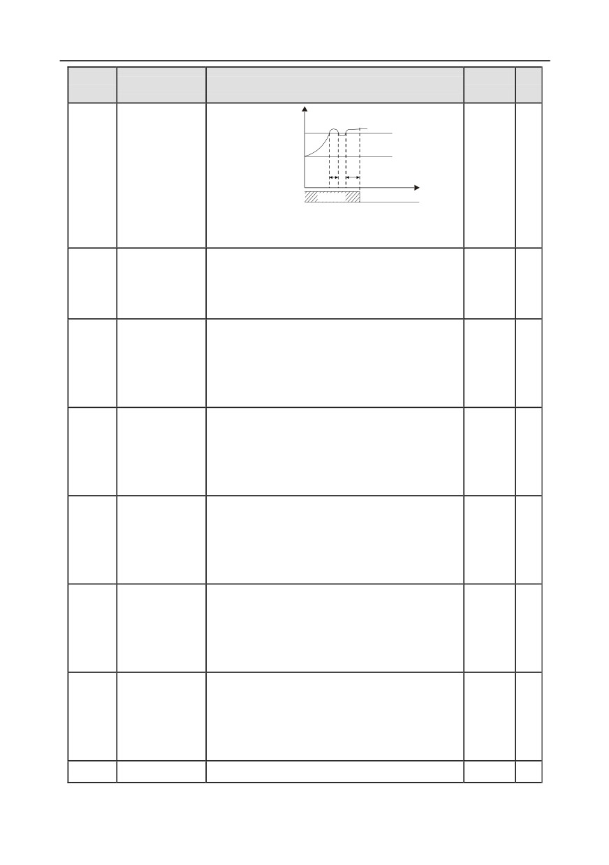
Chapter 6
Function
Default
Modi
Name
Detailed parameter description
code
value
fy
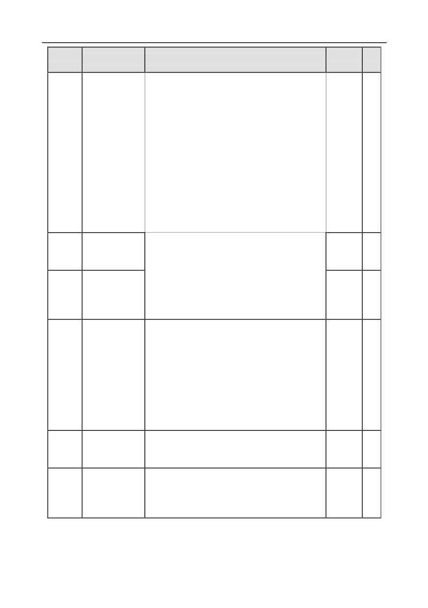
Speed
Actual detection
value
Set detection
value
t1
t2
Time t
Running
Fault outputdEu
t1<t2, so the inverter continues running
t2=P11.15
Setting range: 0.0-10.0s
Automatic
0-1
frequency-reducti
P11.16
0: Invalid
0
○
on during voltage
1: Valid
drop
Proportional
coefficient of
P11.17
voltage regulator
0-1000
100
○
during
undervoltage stall
Integral
coefficient of
P11.18
voltage regulator
0-1000
40
○
during
undervoltage stall
Proportional
coefficient of
P11.19
current regulator
0-1000
25
○
during
undervoltage stall
Integral
coefficient of
P11.20
current regulator
0-2000
150
○
during
undervoltage stall
Proportional
coefficient of
P11.21
voltage regulator
0-1000
60
○
during
overvoltage stall
P11.22
Integral
0-1000
10
○
-185-
Chapter 6
Function
Default
Modi
Name
Detailed parameter description
code
value
fy
coefficient of
voltage regulator
during
overvoltage stall
Proportional
coefficient of
P11.23
current regulator
0-1000
60
○
during
overvoltage stall
Integral
coefficient of
P11.24
current regulator
0-2000
250
○
during
overvoltage stall
Enable inverter
0: Disable
P11.25
0
overload integral
1: Enable
P11.26-
Reserved
0-65536
0
○
P11.27
variables
P12 group Parameters of motor 2
0: Asynchronous motor
P12.00
Type of motor 2
0
◎
1: Synchronous motor
Rated power of
Depend
P12.01
asynchronous
0.1-3000.0kW
◎
on model
motor 2
Rated frequency
P12.02
of asynchronous
0.01Hz-P00.03 (max. output frequency)
50.00Hz
◎
motor 2
Rated speed of
Depend
P12.03
asynchronous
1-36000rpm
◎
on model
motor 2
Rated voltage of
Depend
P12.04
asynchronous
0-1200V
◎
on model
motor 2
Rated current of
Depend
P12.05
asynchronous
0.8-6000.0A
◎
on model
motor 2
Stator resistance
Depend
P12.06
0.001-65.535Ω
○
of asynchronous
on model
-186-
Chapter 6
Function
Default
Modi
Name
Detailed parameter description
code
value
fy
motor 2
Rotor resistance
Depend
P12.07
of asynchronous
0.001-65.535Ω
○
on model
motor 2
Leakage
inductance of
Depend
P12.08
0.1-6553.5mH
○
asynchronous
on model
motor 2
Mutual
inductance of
Depend
P12.09
0.1-6553.5mH
○
asynchronous
on model
motor 2
No-load current
Depend
P12.10
of asynchronous
0.1-6553.5A
○
on model
motor 2
Magnetic
saturation
coefficient 1 of
P12.11
0.0-100.0%
80%
○
iron core of
asynchronous
motor 2
Magnetic
saturation
coefficient 2 of
P12.12
0.0-100.0%
68%
○
iron core of
asynchronous
motor 2
Magnetic
saturation
coefficient 3 of
P12.13
0.0-100.0%
57%
○
iron core of
asynchronous
motor 2
Magnetic
saturation
P12.14
coefficient 4 of
0.0-100.0%
40%
○
iron core of
asynchronous
-187-
Chapter 6
Function
Default
Modi
Name
Detailed parameter description
code
value
fy
motor 2
Rated power of
Depend
P12.15
synchronous
0.1-3000.0kW
◎
on model
motor 2
Rated frequency
P12.16
of synchronous
0.01Hz-P00.03 (max. output frequency)
50.00Hz
◎
motor 2
Number of pole
pairs of
P12.17
1-128
2
◎
synchronous
motor 2
Rated voltage of
Depend
P12.18
synchronous
0-1200V
◎
on model
motor 2
Rated voltage of
Depend
P12.19
synchronous
0.8-6000.0A
◎
on model
motor 2
Stator resistance
Depend
P12.20
of synchronous
0.001-65.535Ω
○
on model
motor 2
Direct-axis
inductance of
Depend
P12.21
0.01-655.35mH
○
synchronous
on model
motor 2
Quadrature-axis
inductance of
Depend
P12.22
0.01-655.35mH
○
synchronous
on model
motor 2
Counter-emf
constant of
P12.23
0-10000V
300
○
synchronous
motor 2
Initial pole
position of
P12.24
synchronous
0-0xFFFF
0x0000
●
motor 2
(reserved)
P12.25
Identification
0%-50% (rated motor current)
10%
●
-188-
Chapter 6
Function
Default
Modi
Name
Detailed parameter description
code
value
fy
current of
synchronous
motor 2
(reserved)
0: No protection
Overload
1: Common motor (with low-speed compensation)
P12.26
protection of
2
◎
2: Frequency-variable motor (without low-speed
motor 2
compensation)
Motor overload multiples M = Iout/(In×K)
In is rated motor current, lout is inverter output
current, K is motor overload protection coefficient.
The smaller the K, the larger the value of M, the
easier the protection.
if M is 116%, protection will be applied when motor
overloads for 1h; if M is 200%, protection will be
Overload
applied when motor overloads for 60s; if M is no less
protection
P12.27
than 400%, protection will be applied immediately.
100.0%
○
coefficient of
Time t
motor 2
1h
1 min
Motor overload multiples
116 %
200 %
Setting range: 20.0%-120.0%
Power display
calibration
P12.28
0.00-3.00
1.00
○
coefficient of
motor 2
0: Display based on the motor type; under this mode,
only parameters related to current motor type will be
Parameter
P12.29
displayed.
0
○
display of motor 2
1: Display all; under this mode, all the parameters
will be displayed.
System inertia of
P12.30
0-30.000kgm2
0.000
○
motor 2
P12.31-
Reserved
0-65535
0
○
P12.32
variables
P13 group Control parameters of synchronous motor
-189-
Chapter 6
Function
Default
Modi
Name
Detailed parameter description
code
value
fy
Reduction rate of
the injection
P13.00
current of
0.0%-100.0% rated motor current
80.0%
○
synchronous
motor
0: Pull-in current
Initial pole
P13.01
1: High-frequency superposition (reserved)
0
◎
detection mode
2: Pulse superposition (reserved)
Pull-in current is the pole position orientation current;
pull-in current 1 is valid within the lower limit of pull-in
current switch-over frequency threshold. If users
P13.02
Pull-in current 1
20.0%
○
need to increase the starting torque, increase the
value of this function code properly.
Setting range: 0.0%-100.0% (rated motor current)
Pull-in current is the pole position orientation current;
pull-in current
2 is valid within the upper limit of
pull-in current switch-over frequency threshold, and
P13.03
Pull-in current 2
10.0%
○
users do not need to change pull-in current 2 under
common situations.
Setting range: 0.0%-100.0% (rated motor current)
Switch-over
P13.04
frequency of
0.00Hz-P00.03 (max. output frequency)
10.00Hz
○
pull-in current
High-frequency
superposition
P13.05
200Hz-1000Hz
500Hz
◎
frequency
(reserved)
High-frequency
P13.06
superposition
0.0-300.0% rated motor voltage
100.0%
◎
voltage
Reserved
P13.07
0-400.0
0.0
○
variables
Control
P13.08
0-0xFFFF
0
○
parameter 1
Control
P13.09
0-655.35
2.00
○
parameter 2
Reserved
P13.10
0-359.9
0
○
variables
-190-
Chapter 6
Function
Default
Modi
Name
Detailed parameter description
code
value
fy
This parameter is used to adjust the responsiveness
of anti-maladjustment function. If the load inertia is
Maladjustment
large, increase the value of this parameter properly,
P13.11
0.5s
○
detection time
however, the responsiveness may slow down
accordingly.
Setting range: 0.0-10.0s
High-frequency
This parameter is valid when the motor speed
compensation
exceeds the rated speed. If motor oscillation
P13.12
coefficient of
0.0
○
occurred, adjust this parameter properly.
synchronous
Setting range: 0.0-100.0%
motor
P13.13-
Reserved
0-65535
0
○
P13.19
variables
P14 group Serial communication function
Setting range: 1-247
When the master is writing frames, and the slave
communication address is set to 0, it is the broadcast
communication address, and all the slaves on the
Local
MODBUS bus will accept this frame, but the slave
P14.00
communication
never responds.
1
○
address
Local communication address is unique in the
communication network, which is the basis for
point-to-point communication between the upper
computer and the inverter.
Note: The slave address cannot be set to 0.
This parameter is used to set the data transmission
speed between upper computer and the inverter.
0: 1200BPS
1: 2400BPS
2: 4800BPS
3: 9600BPS
Communication
P14.01
4: 19200BPS
4
○
baud rate setup
5: 38400BPS
6: 57600BPS
7: 115200BPS
Note: Baud rate of the upper computer must be
the same with the inverter; otherwise,
communication cannot be performed. The larger
-191-
Chapter 6
Function
Default
Modi
Name
Detailed parameter description
code
value
fy
the baud rate, the faster the communication
speed.
The data format of upper computer must be the
same with the inverter; otherwise, communication
cannot be performed.
0: No parity check (N, 8, 1) for RTU
Data bit check
P14.02
1: Even parity (E, 8, 1) for RTU
1
○
setup
2: Odd parity (O, 8, 1) for RTU
3: No parity check (N, 8, 2) for RTU
4: Even parity (E, 8, 2) for RTU
5: Odd parity (O, 8, 2) for RTU
0-200ms
It refers to the time interval from when the data is
received by the inverter to the moment when the
data is sent to the upper computer. If the response
Communication
delay is less than the system processing time, the
P14.03
5
○
response delay
response delay will be subject to system processing
time; if the response delay is longer than the system
processing time, data will be sent to the upper
computer at a delay after data process is done by
system.
0.0 (invalid) -60.0s
This parameter will be invalid if it is set to 0.0;
When it is set to a non-zero value, if the time interval
between current communication and the next
communication exceeds the communication timeout
Communication
P14.04
period, the system will report "485 communication
0.0s
○
timeout period
fault" (CE).
Under common situations, it is set to 0.0. In systems
which have continuous communication, users can
monitor the communication condition by setting this
parameter.
0: Alarm and coast to stop
1: Do not alarm and continue running
Transmission
2: Do not alarm and stop as per the stop mode
P14.05
0
○
error processing
(under communication control mode only)
3: Do not alarm and stop as per the stop mode
(under all control modes)
-192-
Chapter 6
Function
Default
Modi
Name
Detailed parameter description
code
value
fy
0x00-0x11
Ones:
0: Write operation has response
Communication
P14.06
1: Write operation has no response
0x00
○
processing action
Tens:
0: Communication password protection is invalid
1: Communication password protection is valid
P14.07-
Reserved
0-65535
0
●
P14.24
variables
P15 group Functions of communication extension card 1
P15.00-
See the operation manual of communication extension card for details
P15.27
P15.28
Master/slave
0-127
1
◎
CAN
communication
address
P15.29
Master/slave
0: 50Kbps
4
◎
CAN
1: 100 Kbps
communication
2: 125Kbps
baud rate
3: 250Kbps
selection
4: 500Kbps
5: 1M bps
P15.30
Master/slave
0.0 (invalid)-300.0s
0.0s
○
CAN
communication
timeout period
P15.31-
See the operation manual of communication extension card for details
P15.69
P16 group Functions of communication extension card 2
P16.00-
See the operation manual of communication extension card for details
P16.23
Identification
0.0-600.0s
time for the
0.0-
P16.24
If it is set to 0.0, identification fault will not be
0.0
extension card in
600.00
detected
card slot 1
Identification
0.0-600.0s
0.0-
P16.25
time for the
0.0
If it is set to 0.0, offline fault will not be detected
600.00
extension card in
-193-
Chapter 6
Function
Default
Modi
Name
Detailed parameter description
code
value
fy
card slot 2
Identification
time for the
0.0-600.0s
P16.26
/
/
extension card in
If it is set to 0.0, offline fault will not be detected
card slot 3
Communication
timeout period of
0.0-600.0s
P16.27
/
/
extension card in
If it is set to 0.0, offline fault will not be detected
card slot 1
Communication
timeout period of
0.0-600.0s
P16.28
/
/
extension card in
If it is set to 0.0, offline fault will not be detected
card slot 2
Communication
timeout period of
0.0-600.0s
P16.29
/
/
extension card in
If it is set to 0.0, offline fault will not be detected
card slot 3
P16.30-
See the operation manual of communication extension card for details
P16.69
P17 group State-check functions
Display current set frequency of the inverter.
P17.00
Set frequency
50.00Hz
●
Range: 0.00Hz-P00.03
Display current output frequency of the inverter.
P17.01
Output frequency
0.00Hz
●
Range: 0.00Hz-P00.03
Display current ramps reference frequency of the
Ramps reference
P17.02
inverter.
0.00Hz
●
frequency
Range: 0.00Hz-P00.03
Display current output voltage of the inverter.
P17.03
Output voltage
0V
●
Range: 0-1200V
Display the valid value of current output current of
P17.04
Output current
the inverter.
0.0A
●
Range: 0.0-5000.0A
Display current motor speed.
P17.05
Motor speed
0 RPM
●
Range: 0-65535RPM
Display current torque current of the inverter.
P17.06
Torque current
0.0A
●
Range: -3000.0-3000.0A
Display current exciting current of the inverter.
P17.07
Exciting current
0.0A
●
Range: -3000.0-3000.0A
-194-