Goodrive350 Series High-performance Multi-function Inver ter. Operation manual - page 9
Appendix C
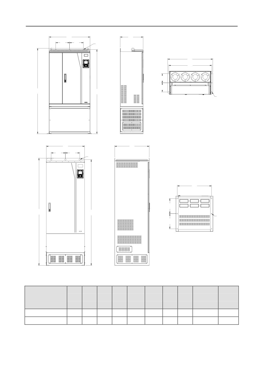
C.4.3 Floor installation dimensions
W4
D1
W2
W2
3- ø13.0
W1
W3
D2
D2
H1
H2
6- ø12.0
Fig C.12 Floor installation diagram of inverters of 380 V, 220 to 315 kW
W1
D1
W2
W2
3- ø22.0
W3
D2
H1
H2
6- ø12.0
D2
Fig C.13 Floor installation diagram of inverters of 380 V, 355 to 500 kW
Table C.3 Floor installation dimensions of 380 V inverters (unit: mm)
Installation
Fixing
Inverter
W1
W2
W3
W4
H1
H2
D1
D2
hole
screw
specification
diameter
220kW-315kW
750
230
714
680
1410
1390
380
150
13\12
M12/M10
355kW-500kW
620
230
572
-
1700
1678
560
240
22\12
M20/M10
-315-
Appendix C
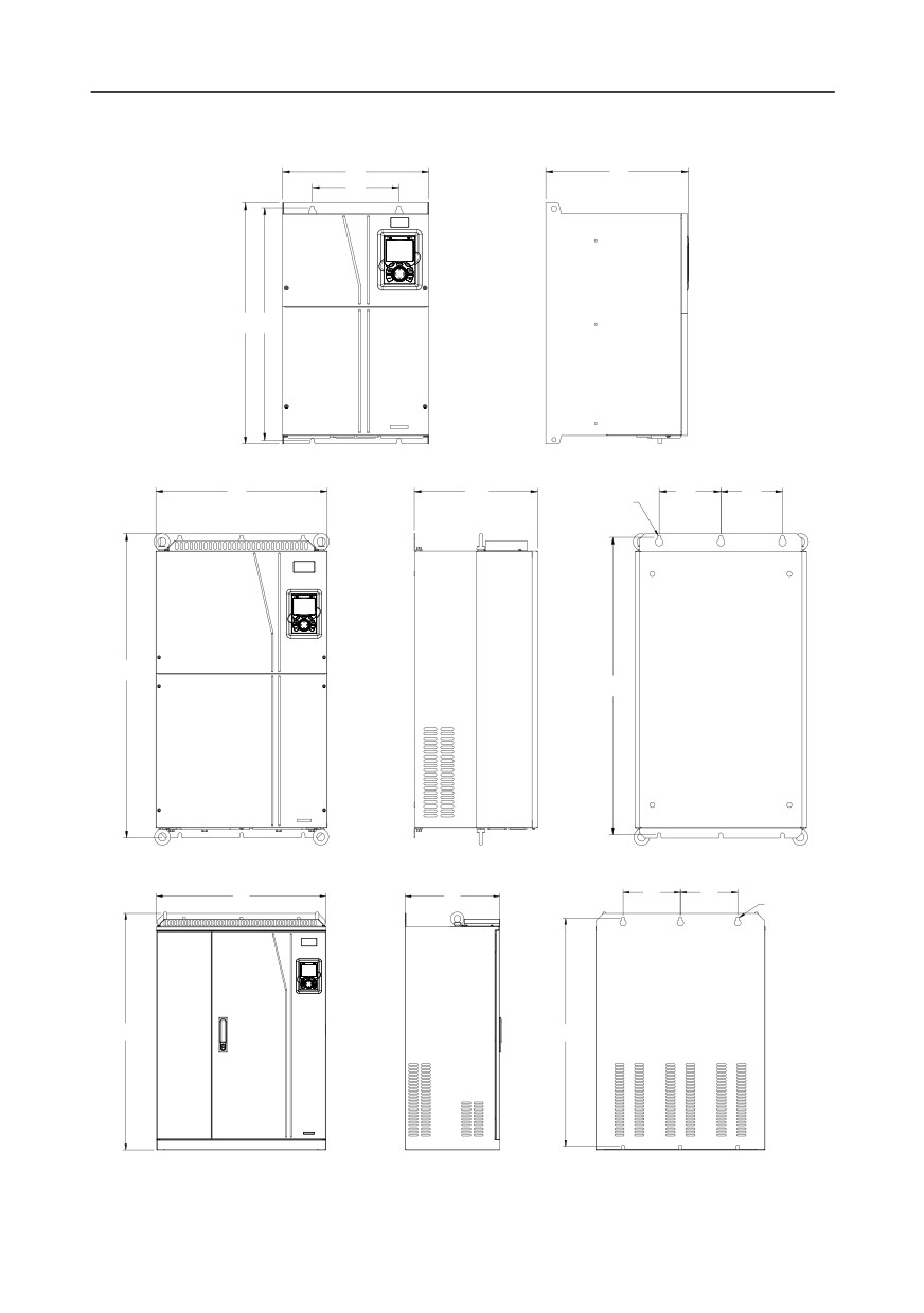
C.5 Dimensions of Inverters of AC 3PH 520V (-15%)-690V (+10%)
C.5.1 Wall-mounting dimensions
W1
D1
W2
H1 H2
Fig C.14 Wall-mounting diagram of inverters of 660 V, 22 to 132 kW
W1
D1
W2
W2
6- ø11.0
H1
H2
Fig C.15 Wall-mounting diagram of inverters of 660 V, 160 to 220 kW
W1
D1
W2
W2
6- ø13.0
H1
H2
Fig C.16 Wall-mounting diagram of inverters of 660 V, 250 to 355 kW
-316-
Appendix C
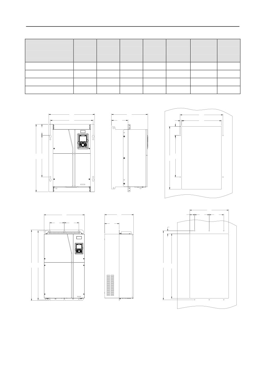
Table C.4 Wall-mounting dimensions of 660 V inverters (unit: mm)
Installation
Fixing
Inverter
W1
W2
H1
H2
D1
hole
screw
specification
diameter
22kW-45kW
270
130
555
540
325
7
M6
55kW-132kW
325
200
680
661
365
9.5
M8
160kW-220kW
500
180
870
850
360
11
M10
250kW-355kW
680
230
960
926
380
13
M12
C.5.2 Flange installation dimensions
W1
D1
W2
W2
D2
W4
W3
98.0
H4
H1
H2
H2
H3
Fig C.17 Flange installation diagram of inverters of 660 V, 22 to 132 kW
W3
W1
D1
W4
W2
W2
W2
W2
D2
H4
H1
H2
H2
H3
Fig C.18 Flange installation diagram of inverters of 660 V, 160 to 220 kW
Table C.5 Flange installation dimensions of 660 V inverters (unit: mm)
-317-
Appendix C
Installation
Fixing
Inverter
W1
W2
W3
W4
H1
H2
H3
H4
D1
D2
hole
screw
specification
diameter
22kW-45kW
270
130
261
65.5
555
540
516
17
325
167
7
M6
55kW-132kW
325
200
317
58.5
680
661
626
23
363
182
9.5
M8
160kW-220kW
500
180
480
60
870
850
796
37
358
178.5
11
M10
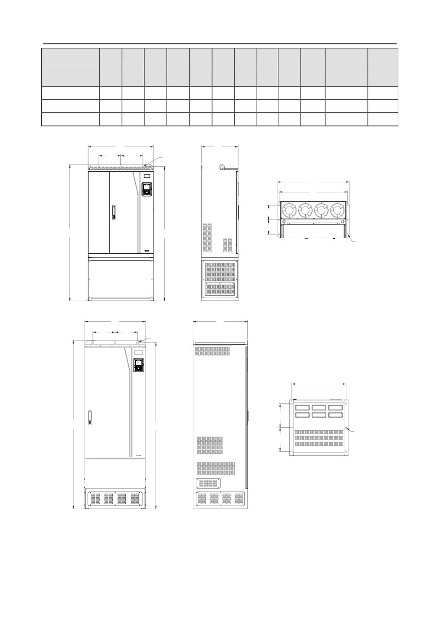
C.5.3 Floor installation dimensions
W4
D1
W2
W2
3- ø13.0
W1
W3
D2
D2
H1
H2
6- ø12.0
Fig C.19 Floor installation diagram of inverters of 660 V, 250 to 355 kW
W1
D1
W2
W2
3- ø22.0
W3
D2
H1
H2
6- ø12.0
D2
Fig C.20 Floor installation diagram of inverters of 660 V, 400 to 630 kW
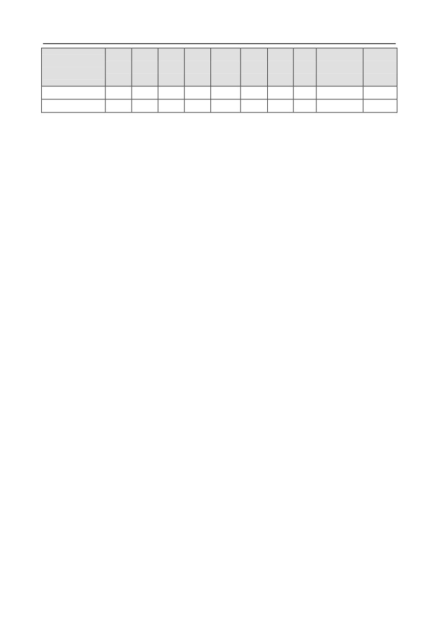
Table C.6 Floor installation dimensions of 660 V inverters (unit: mm)
-318-
Appendix C
Installation
Fixing
Inverter
W1
W2
W3
W4
H1
H2
D1
D2
hole
screw
specification
diameter
250kW-355kW
750
230
714
680
1410
1390
380
150
13\12
M12/M10
400kW-630kW
620
230
572
\
1700
1678
560
240
22\12
M20/M10
-319-
Appendix D
Appendix D Optional peripheral accessories
D.1 What this chapter contains
This chapter describes how to select optional accessories of Goodrive350 series inverters.
D.2 Wiring of peripheral accessories
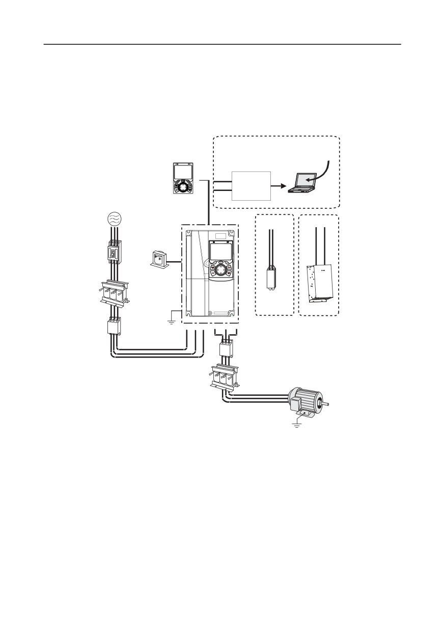
The following figure shows the external wiring of a Goodrive350 series inverter.
Upper PC
LCD keypad
software
485+
RS485-
RS232
485-
converter
Standard
PC
Power supply
PB
+
-
+
Breaker
P1
+
DC reactor
Input reactor
Brake
resistor
Brake unit
Earth
Input filter
Output filter
Output reactor
Motor
Earth
Note:
1. Inverters of 380 V, 37 kW or lower are equipped with built-in brake units, and inverters of 45 kW
to 110 kW can be configured with optional built-in brake units.
2. Inverters of 380 V, 18.5 kW to 110 kW are equipped with built-in DC reactors.
3. P1 terminals are equipped only for inverters of 380 V, 132 kW or higher, which enable the
inverters to be directly connected to external DC reactors.
4. P1 terminals are equipped for all inverters of the 660 V series or higher, which enable the
inverters to be directly connected to external DC reactors.
5. The brake units INVT's DBU series standard brake units. For details, see the DBU operation
-320-
Appendix D
manual.
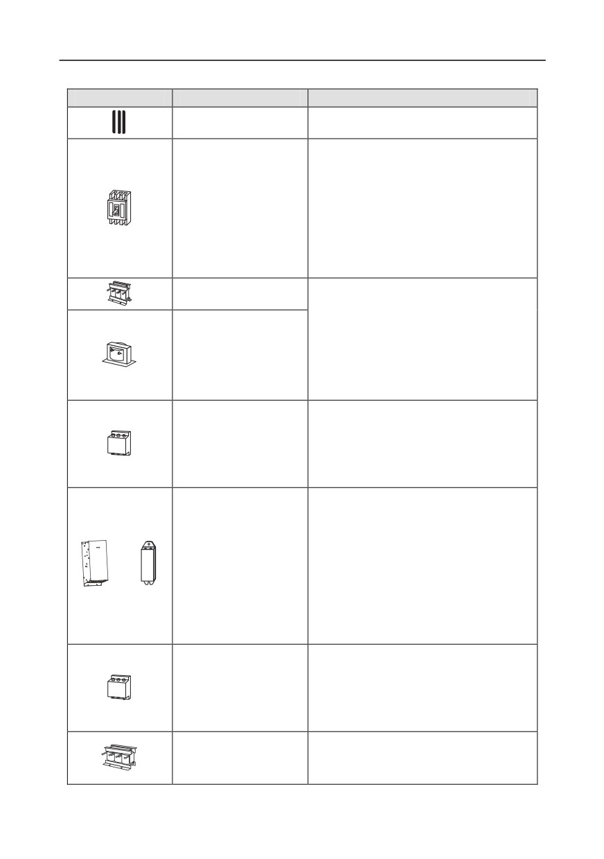
Image
Name
Description
Cable
Accessory for signal transmission
Device for electric shock prevention and
protection against short-to-ground that may
cause current leakage and fire. Select
residual-current circuit breakers
(RCCBs)
Breaker
that are applicable to inverters and can
restrict high-order harmonics, and of which
the rated sensitive current for one inverter is
larger than 30 mA.
Accessories used to improve the current
Input reactor
adjustment coefficient on the input side of
the inverter, and thus restrict high-order
harmonic currents.
DC reactor
Inverters of 380 V, 132 kW or higher and 660
V series can be directly connected to
external DC reactors.
Accessory that restricts the electromagnetic
interference generated by the inverter and
Input filter
transmitted to the public grid through the
power cable. Try to install the input filter near
the input terminal side of the inverter.
Accessories used to consume the
regenerative energy of the motor to reduce
the deceleration time.
Inverters of 380 V, 37 kW or lower need only
Brake unit or brake
to be configured with brake resistors, those
resistor
or
of 380V, 132 kW or higher and 660 V series
also need to be configured with brake units,
and those of 380V, 45 kW to 110 kW can be
configured with optional built-in brake units.
Accessory used to restrict interference
generated in the wiring area on the output
Output filter
side of the inverter. Try to install the output
filter near the output terminal side of the
inverter.
Accessory used to lengthen the valid
Output reactor
transmission distance of the inverter, which
effectively restrict the transient high voltage
-321-
Appendix D
Image
Name
Description
generated during the switch-on and
switch-off of the IGBT module of the inverter.
D.3 Power supply
Refer to the electrical installation.
Ensure that the voltage class of the inverter is consistent with that of the
grid.
D.4 Cables
D.4.1 Power cables
The sizes of the input power cables and motor cables must meet the local regulation.
•
The input power cables and motor cables must be able to carry the corresponding load currents.
•
The maximum temperature margin of the motor cables in continuous operation cannot be lower
than 70°C.
•
The conductivity of the PE grounding conductor is the same as that of the phase conductor, that
is, the cross-sectional areas are the same.
•
For details about the EMC requirements, see Appendix B "Technical data."
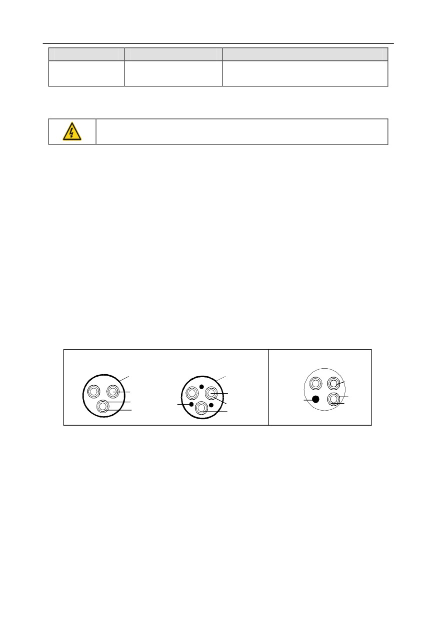
To meet the EMC requirements stipulated in the CE standards, you must use symmetrical shielded
cables as motor cables (as shown in the following figure).
Four-core cables can be used as input cables, but symmetrical shielded cables are recommended.
Compared with four-core cables, symmetrical shielded cables can reduce electromagnetic radiation
as well as the current and loss of the motor cables.
Symmetrical shielded cable
Fo-r-core cable
PE conductor and
shield layer
Shield layer
Conductor
Conductor
Conductor
Jacket
Jacket
PE
Jacket
PE
Insulator
Insulator
Insulator
Note: If the conductivity of the shield layer of the motor cables cannot meet the requirements,
separate PE conductors must be used.
To protect the conductors, the cross-sectional area of the shielded cables must be the same as that of
the phase conductors if the cable and conductor are made of materials of the same type. This
reduces grounding resistance, and thus improves impedance continuity.
To effectively restrict the emission and conduction of radio frequency
(RF) interference, the
conductivity of the shielded cable must at least be 1/10 of the conductivity of the phase conductor.
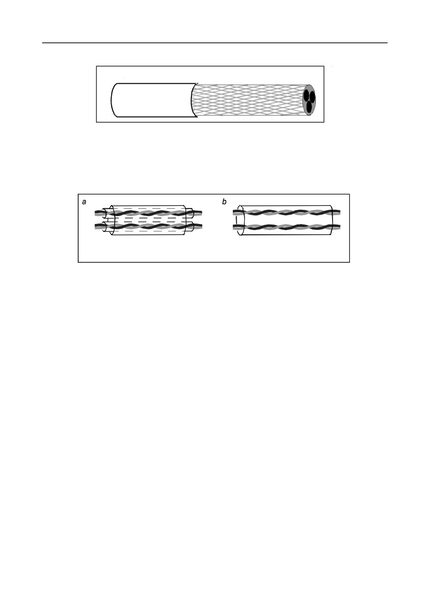
This requirement can be well met by a copper or aluminium shield layer. The following figure shows
the minimum requirement on motor cables of an inverter. The cable must consist of a layer of
spiral-shaped copper strips. The denser the shield layer is, the more effectively the electromagnetic
-322-
Appendix D
interference is restricted.
Insulating layer
Shield layer
Cross-section of the cable
D.4.2 Control cables
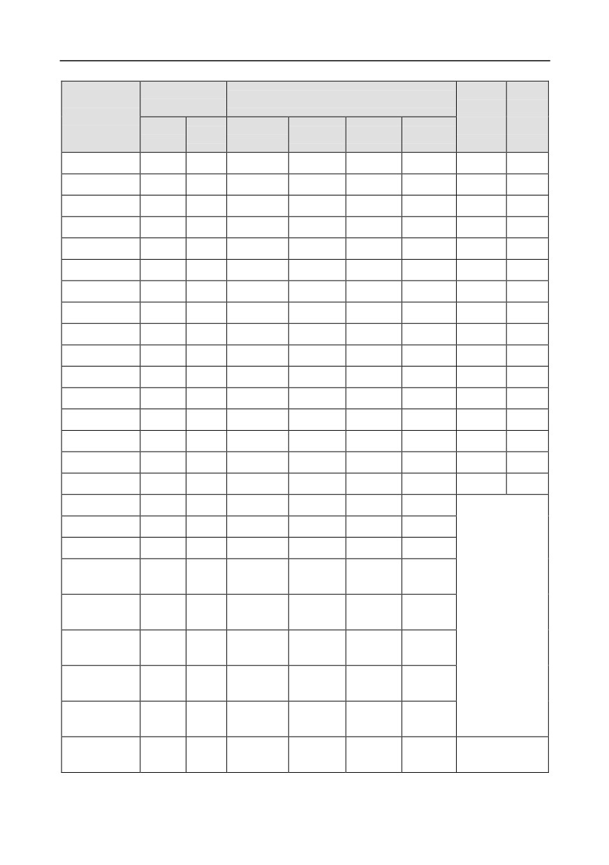
All analog control cables and cables used for frequency input must be shielded cables. Analog signal
cables need to be double-shielded twisted-pair cables (as shown in figure a). Use one separate
shielded twisted pair for each signal. Do not use the same ground wire for different analog signals.
Multiple double-shielded twisted-pair cables
Multiple shielded twisted-pair cables
Power cable arrangement
For low-voltage digital signals, double-shielded cables are recommended, but shielded or unshielded
twisted pairs (as shown in figure b) also can be used. For frequency signals, however, only shielded
cables can be used.
Relay cables need to be those with metal braided shield layers.
Keypads need to be connected by using network cables. In complicated electromagnetic
environments, shielded network cables are recommended.
Note: Analog signals and digital signals cannot use the same cables, and their cables must be
arranged separately.
Do not perform any voltage endurance or insulation resistance tests, such as high-voltage insulation
tests or using a megameter to measure the insulation resistance, on the inverter or its components.
Insulation and voltage endurance tests have been performed between the main circuit and chassis of
each inverter before delivery. In addition, voltage limiting circuits that can automatically cut off the test
voltage are configured inside the inverters.
Note: Check the insulation conditions of the input power cable of an inverter according to the local
regulations before connecting it.
-323-
Appendix D
D.4.2.1 AC 3PH 380V (-15%)-440V (+10%)
Recommended
Terminal
Tighten
Size of connectable cable (mm2)
cable size (mm2)
screw
ing
Inverter model
RST
RST
specifica
torque
PE
P1, (+)
PB, (+), (-)
PE
UVW
UVW
tion
(Nm)
GD350-1R5G-4
2.5
2.5
2.5-6
2.5-6
2.5-6
2.5-6
M4
1.2-1.5
GD350-2R2G-4
2.5
2.5
2.5-6
2.5-6
2.5-6
2.5-6
M4
1.2-1.5
GD350-004G-4
2.5
2.5
2.5-6
2.5-6
2.5-6
2.5-6
M4
1.2-1.5
GD350-5R5G-4
2.5
2.5
2.5-6
2.5-6
2.5-6
2.5-6
M4
1.2-1.5
GD350-7R5G-4
4
4
2.5-6
4-6
4-6
2.5-6
M4
1.2-1.5
GD350-011G-4
6
6
4-10
4-10
4-10
4-10
M5
2.3
GD350-015G-4
6
6
4-10
4-10
4-10
4-10
M5
2.3
GD350-018G-4
10
10
10-16
10-16
10-16
10-16
M5
2.3
GD350-022G-4
16
16
10-16
10-16
10-16
10-16
M5
2.3
GD350-030G-4
25
16
25-50
25-50
25-50
16-25
M6
2.5
GD350-037G-4
25
16
25-50
25-50
25-50
16-25
M6
2.5
GD350-045G-4
35
16
35-70
35-70
35-70
16-35
M8
10
GD350-055G-4
50
25
35-70
35-70
35-70
16-35
M8
10
GD350-075G-4
70
35
35-70
35-70
35-70
16-35
M8
10
GD350-090G-4
95
50
70-120
70-120
70-120
50-70
M12
35
GD350-110G-4
120
70
70-120
70-120
70-120
50-70
M12
35
GD350-132G-4
185
95
95-300
95-300
95-300
95-240
GD350-160G-4
240
120
95-300
95-300
95-300
120-240
GD350-185G-4
95×2P
95
95-150
70-150
70-150
35-95
95×2P
95×2P
95×2P
GD350-200G-4
95×2P
120
120-240
Nuts are used as
-150×2P
-150×2P
-150×2P
terminals, so it is
95×2P -
95×2P -
95×2P -
GD350-220G-4
150×2P
150
150-240
recommended that
150×2P
150×2P
150×2P
you use a wrench
95×4P
95×4P
95×4P
95×2P
GD350-250G-4
95×4P
95×2P
or sleeve.
–150×4P
-150×4P
-150×4P
-150×2P
95×4P
95×4P
95×4P
95×2P
GD350-280G-4
95×4P
95×2P
–150×4P
-150×4P
-150×4P
-150×2P
95×4P
95×4P
95×4P
95×2P
GD350-315G-4
95×4P
95×4P
–150×4P
-150×4P
-150×4P
-150×2P
95×4P
95×4P
95×4P
95×2P
GD350-355G-4
95×4P
95×4P
-150×4P
-150×4P
-150×4P
-150×2P
-324-
Appendix D
Recommended
Terminal
Tighten
Size of connectable cable (mm2)
cable size (mm2)
screw
ing
Inverter model
RST
RST
specifica
torque
PE
P1, (+)
PB, (+), (-)
PE
UVW
UVW
tion
(Nm)
95×4P
95×4P
95×4P
95×2P
GD350-400G-4
150×4P
150×2P
–150×4P
-150×4P
-150×4P
-150×2P
95×4P
95×4P
95×4P
95×2P
GD350-450G-4
150*4P
150*2P
-150×4P
-150×4P
-150×4P
-150×2P
95×4P
95×4P
95×4P
95×2P
GD350-500G-4
150×4P
150×2P
–150×4P
-150×4P
-150×4P
-150×2P
Note:
1.
Cables of the sizes recommended for the main circuit can be used in scenarios where the
ambient temperature is lower than 40°C, the wiring distance is shorter than 100 m, and the
current is the rated current.
2.
The terminals P1, (+), and (-) are used to connect to DC reactors and brake accessories.
D.4.2.2 AC 3PH 520V (-15%)-690V (+10%)
Recommended
cable size
Size of connectable cable (mm2)
Terminal
Tightening
Inverter model
(mm2)
screw
torque
RST
RST
PB, (+),
specification
(Nm)
PE
P1, (+)
PE
UVW
UVW
(-)
GD350-022G-6
10
10
10-16
6-16
6-10
10-16
M8
9-11
GD350-030G-6
10
10
10-16
6-16
6-10
10-16
M8
9-11
GD350-037G-6
16
16
16-25
16-25
6-10
16-25
M8
9-11
GD350-045G-6
16
16
16-25
16-35
16-25
16-25
M8
9-11
GD350-055G-6
25
16
16-25
16-35
16-25
16-25
M10
18-23
GD350-075G-6
35
16
35-50
25-50
25-50
16-50
M10
18-23
GD350-090G-6
35
16
35-50
25-50
25-50
16-50
M10
18-23
GD350-110G-6
50
25
50-95
50-95
25-95
25-95
M10
18-23
GD350-132G-6
70
35
70-95
70-95
25-95
35-95
M10
18-23
GD350-160G-6
95
50
95-150
95-150
25-150
50-150
GD350-185G-6
95
50
95-150
95-150
25-150
50-150
Nuts are used as
GD350-200G-6
120
70
120-300
120-300
35-300
70-240
terminals, so it is
GD350-220G-6
185
95
120-300
120-300
35-300
95-240
recommended that you
use a wrench or sleeve.
GD350-250G-6
185
95
185-300
185-300
35-300
95-240
GD350-280G-6
240
120
240-300
240-300
70-300
120-240
-325-
Appendix D
Recommended
cable size
Size of connectable cable (mm2)
Terminal
Tightening
Inverter model
(mm2)
screw
torque
RST
RST
PB, (+),
specification
(Nm)
PE
P1, (+)
PE
UVW
UVW
(-)
95×2P-
95×2P
95×2P
GD350-315G-6
95×2P
120
120-300
150×2P
-150×2P
-150×2P
95×2P-
95×2P
95×2P
GD350-355G-6
95×2P
150
150-300
150×2P
-150×2P
-150×2P
150×2P-
95×2P
95×2P
GD350-400G-6
150×2P
150
150-300
300×2P
-150×2P
-150×2P
95×4P
95×4P
95×4P
95×2P
GD350-450G-6
95×4P
95×2P
–150×4P -150×4P
-150×4P
-150×2P
95×4P
95×4P
95×4P
95×2P
GD350-500G-6
95×4P
95×2P
–150×4P -150×4P
-150×4P
-150×2P
95×4P
95×4P
95×4P
95×4P
GD350-560G-6
95×4P
95×4P
–150×4P -150×4P
-150×4P
-150×4P
150×4P
150×4P
150×4P
150×4P
GD350-630G-6
150×4P
150×2P
–300×4P -300×4P
-300×4P
-240×4P
Note:
1. Cables of the sizes recommended for the main circuit can be used in scenarios where the
ambient temperature is lower than 40°C, the wiring distance is shorter than 100 m, and the
current is the rated current.
2. The terminals P1, (+), and (-) are used to connect to DC reactors and brake accessories.
D.4.3 Cable arrangement
Motor cables must be arranged away from other cables. The motor cables of several inverters can be
arranged in parallel. It is recommended that you arrange the motor cables, input power cables, and
control cables separately in different trays. The output dU/dt of the inverters may increase
electromagnetic interference on other cables. Do not arrange other cables and the motor cables in
parallel.
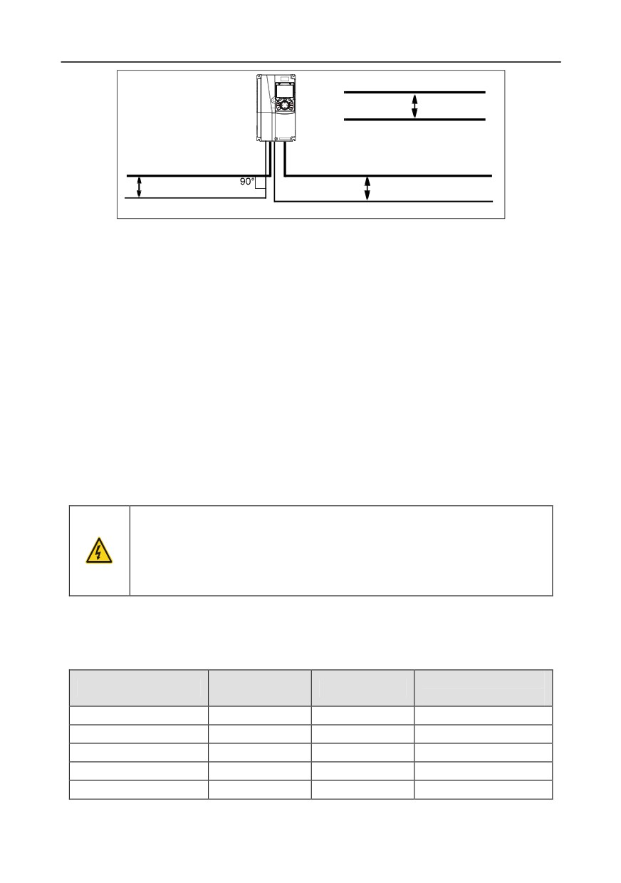
If a control cable and power cable must cross each other, ensure that the angle between them is 90
degrees.
The cable trays must be connected properly and well grounded. Aluminum trays can implement local
equipotential.
The following figure shows the cable arrangement distance requirements.
-326-
Appendix D
Motor cable
Min. distance:
Power cable
300 mm
Input power cable
Motor cable
Min. distance:
Min. distance: 500 mm
200 mm
Control cable
Control cable
Cable arrangement distances
D.4.4 Insulation inspection
Check the motor and the insulation conditions of the motor cable before running the motor.
1. Ensure that the motor cable is connected to the motor, and then remove the motor cable from the
U, V, and W output terminals of the inverter.
2. Use a megameter of 500 V DC to measure the insulation resistance between each phase
conductor and the protection grounding conductor. For details about the insulation resistance of
the motor, see the description provided by the manufacturer.
Note: The insulation resistance is reduced if it is damp inside the motor. If it may be damp, you
need to dry the motor and then measure the insulation resistance again.
D.5 Breaker and electromagnetic contactor
You need to add a fuse to prevent overload.
You need to configure a manually manipulated molded case circuit breaker (MCCB) between the AC
power supply and inverter. The breaker must be locked in the open state to facilitate installation and
inspection. The capacity of the breaker needs to be 1.5 to 2 times the rated current of the inverter.
According to the working principle and structure of breakers, if the
manufacturer's regulation is not followed, hot ionized gases may escape
from the breaker enclosure when a short-circuit occurs. To ensure safe use,
exercise extra caution when installing and placing the breaker. Follow the
manufacturer's instructions.
To ensure safety, you can configure an electromagnetic contactor on the input side to control the
switch-on and switch-off of the main circuit power, so that the input power supply of the inverter can
be effectively cut off when a system fault occurs.
D.5.1 Breakers and electromagnetic contactors for AC 3PH 380V (-15%)-440V (+10%)
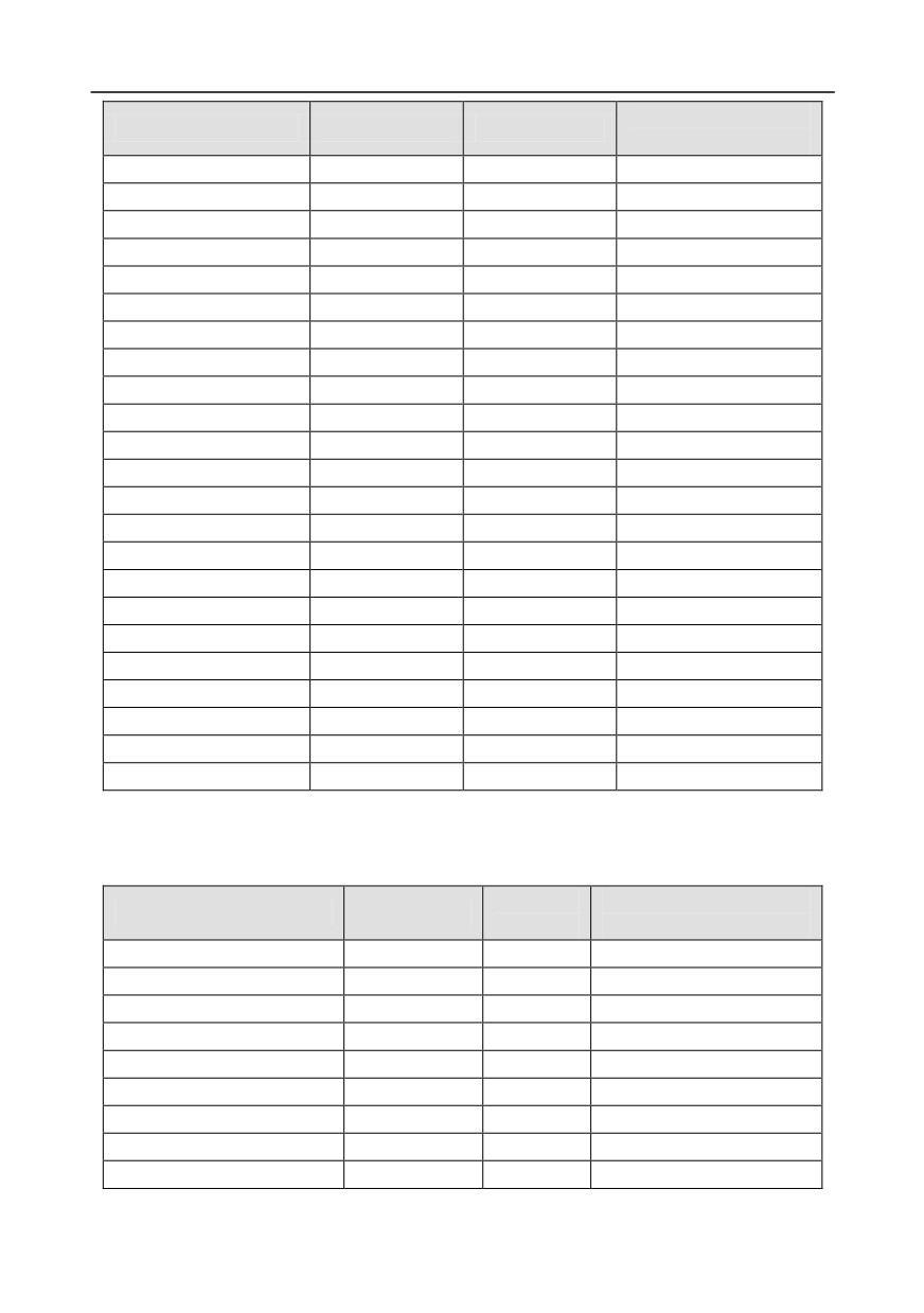
Rated current of the
Inverter model
Fuse (A
Breaker (A)
contactor (A)
GD350-1R5G-4
1
16
10
GD350-2R2G-4
17.4
16
10
GD350-004G-4
30
25
16
GD350-5R5G-4
45
25
16
GD350-7R5G-4
60
40
25
-327-
Appendix D
Rated current of the
Inverter model
Fuse (A
Breaker (A)
contactor (A)
GD350-011G-4
78
63
32
GD350-015G-4
105
63
50
GD350-018G-4
114
100
63
GD350-022G-4
138
100
80
GD350-030G-4
186
125
95
GD350-037G-4
228
160
120
GD350-045G-4
270
200
135
GD350-055G-4
315
200
170
GD350-075G-4
420
250
230
GD350-090G-4
480
315
280
GD350-110G-4
630
400
315
GD350-132G-4
720
400
380
GD350-160G-4
870
630
450
GD350-185G-4
1110
630
580
GD350-200G-4
1110
630
580
GD350-220G-4
1230
800
630
GD350-250G-4
1380
800
700
GD350-280G-4
1500
1000
780
GD350-315G-4
1740
1200
900
GD350-355G-4
1860
1280
960
GD350-400G-4
2010
1380
1035
GD350-450G-4
2445
1630
1222
GD350-500G-4
2505
1720
1290
Note: The accessory specifications described in the preceding table are ideal values. You can select
accessories based on the actual market conditions, but try not to use those with lower values.
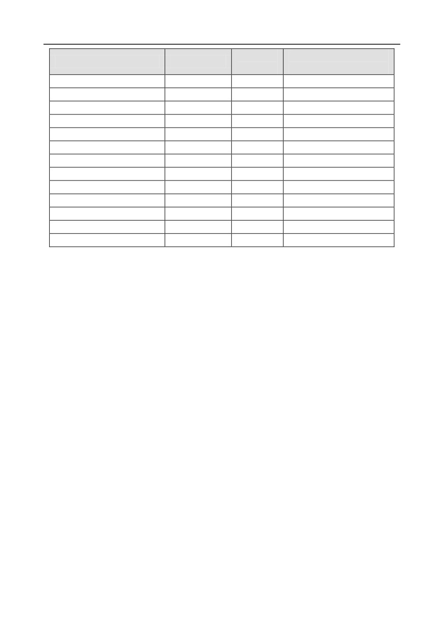
D.5.2 Breakers and electromagnetic contactors for AC 3PH 520V (-15%)-690V (+10%)
Breaker
Rated current of the
Inverter model
Fuse (A
(A)
contactor (A)
GD350-022G-6
105
63
50
GD350-030G-6
105
63
50
GD350-037G-6
114
100
63
GD350-045G-6
138
100
80
GD350-055G-6
186
125
95
GD350-075G-6
270
200
135
GD350-090G-6
270
200
135
GD350-110G-6
315
200
170
GD350-132G-6
420
250
230
-328-
Appendix D
Breaker
Rated current of the
Inverter model
Fuse (A
(A)
contactor (A)
GD350-160G-6
480
315
280
GD350-185G-6
480
315
280
GD350-200G-6
630
400
315
GD350-220G-6
720
400
380
GD350-250G-6
720
400
380
GD350-280G-6
870
630
450
GD350-315G-6
1110
630
580
GD350-350G-6
1110
630
580
GD350-400G-6
1230
800
630
GD350-450G-6
1470
960
735
GD350-500G-6
1500
1000
780
GD350-560G-6
1740
1200
900
GD350-630G-6
2010
1380
1035
Note: The accessory specifications described in the preceding table are ideal values. You can select
accessories based on the actual market conditions, but try not to use those with lower values.
D.6 Reactors
When the voltage of the grid is high, the transient large current that flows into the input power circuit
may damage rectifier components. You need to configure an AC reactor on the input side, which can
also improve the current adjustment coefficient on the input side.
When the distance between the inverter and motor is longer than 50 m, the parasitic capacitance
between the long cable and ground may cause large leakage current, and overcurrent protection of
the inverter may be frequently triggered. To prevent this from happening and avoid damage to the
motor insulator, compensation must be made by adding an output reactor. When an inverter is used
to drive multiple motors, take the total length of the motor cables (that is, sum of the lengths of the
motor cables) into account. When the total length is longer than 50 m, an output reactor must be
added on the output side of the inverter. If the distance between the inverter and motor is 50 m to 100
m, select the reactor according to the following table. If the distance is longer than 100 m, contact
INVT's technical support technicians.
DC reactors can be directly connected to inverters of 380 V, 132 kW or higher and the 660 V series.
DC reactors can improve the power factor, avoid damage to bridge rectifiers caused due to large input
current of the inverter when large-capacity transformers are connected, and also avoid damage to the
rectification circuit caused due to harmonics generated by grid voltage transients or phase-control
loads.
-329-
Appendix D
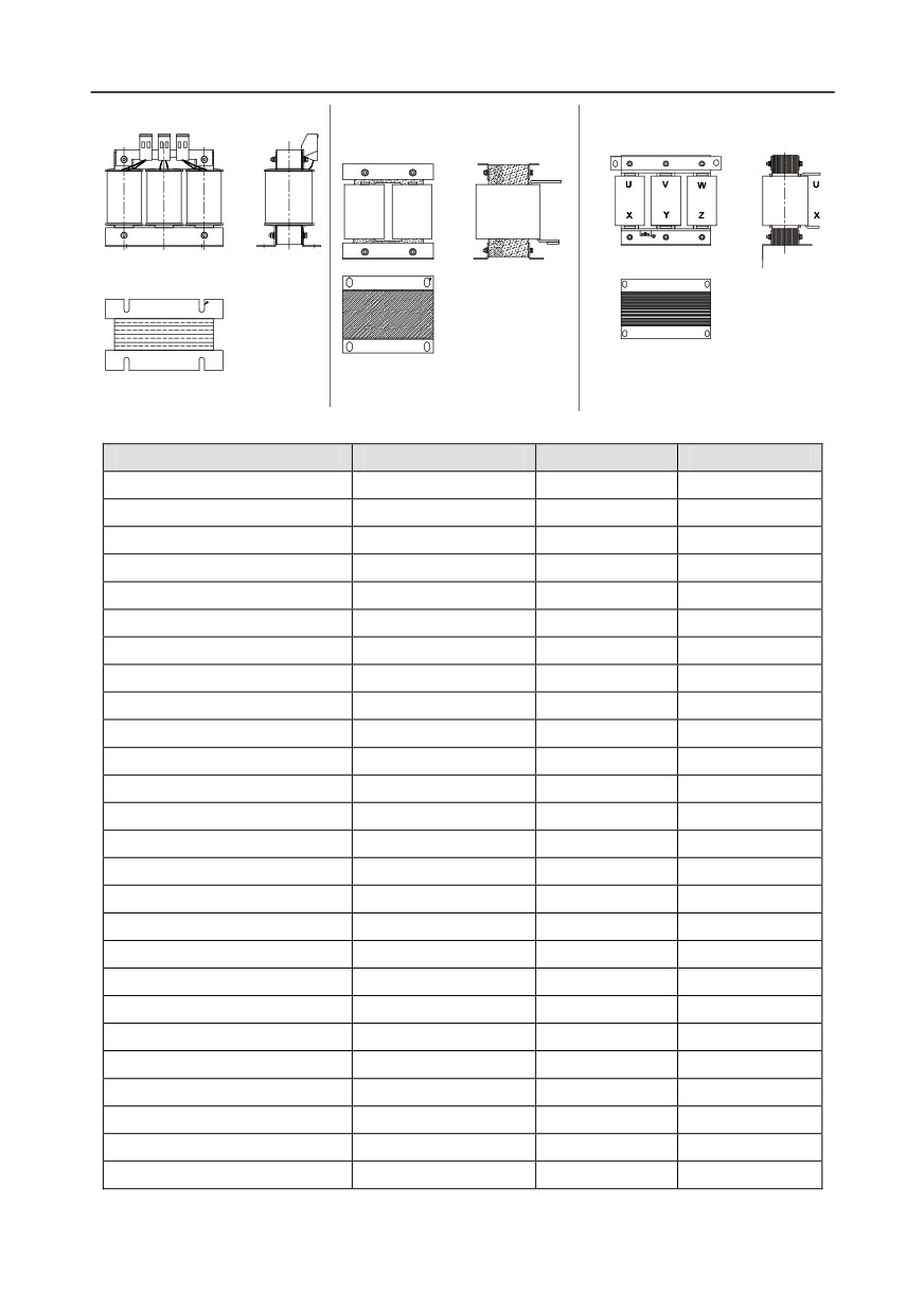
Input reactor
DC reactor
Output reactor
D.6.1 Reactors for AC 3PH 380V (-15%)-440V (+10%)
Inverter model
Input reactor
DC reactor
Output reactor
GD350-1R5G-4
ACL2-1R5-4
/
OCL2-1R5-4
GD350-2R2G-4
ACL2-2R2-4
/
OCL2-2R2-4
GD350-004G-4
ACL2-004-4
/
OCL2-004-4
GD350-5R5G-4
ACL2-5R5-4
/
OCL2-5R5-4
GD350-7R5G-4
ACL2-7R5-4
/
OCL2-7R5-4
GD350-011G-4
ACL2-011-4
/
OCL2-011-4
GD350-015G-4
ACL2-015-4
/
OCL2-015-4
GD350-018G-4
ACL2-018-4
/
OCL2-018-4
GD350-022G-4
ACL2-022-4
/
OCL2-022-4
GD350-030G-4
ACL2-030-4
/
OCL2-030-4
GD350-037G-4
ACL2-037-4
/
OCL2-037-4
GD350-045G-4
ACL2-045-4
/
OCL2-045-4
GD350-055G-4
ACL2-055-4
/
OCL2-055-4
GD350-075G-4
ACL2-075-4
/
OCL2-075-4
GD350-090G-4
ACL2-0110-4
/
OCL2-110-4
GD350-110G-4
ACL2-110-4
/
OCL2-110-4
GD350-132G-4
ACL2-132-4
DCL2-132-4
OCL2-132-4
GD350-160G-4
ACL2-160-4
DCL2-160-4
OCL2-160-4
GD350-185G-4
ACL2-200-4
DCL2-200-4
OCL2-200-4
GD350-200G-4
ACL2-200-4
DCL2-220-4
OCL2-200-4
GD350-220G-4
ACL2-250-4
DCL2-280-4
OCL2-250-4
GD350-250G-4
ACL2-250-4
DCL2-280-4
OCL2-250-4
GD350-280G-4
ACL2-280-4
DCL2-280-4
OCL2-280-4
GD350-315G-4
ACL2-315-4
DCL2-315-4
OCL2-315-4
GD350-350G-4
Standard
DCL2-400-4
OCL2-350-4
GD350-400G-4
Standard
DCL2-400-4
OCL2-400-4
-330-
Appendix D
Inverter model
Input reactor
DC reactor
Output reactor
GD350-450G-4
Standard
DCL2-500-4
OCL2-500-4
GD350-500G-4
Standard
DCL2-500-4
OCL2-500-4
Note:
1. The rated input voltage drop of input reactors is 2%±15%.
2. The current adjustment coefficient on the input side of the inverter is higher than 90% after a DC
reactor is configured.
3. The rated output voltage drop of output reactors is 1%±15%.
4. The preceding table describes external accessories. You need to specify the ones you choose
when purchasing accessories.
D.6.2 Reactors for AC 3PH 520V (-15%)-690V (+10%)
Inverter model
Input reactor
DC reactor
Output reactor
GD350-022G-6
ACL2-030G-6
DCL2-030G-6
OCL2-030G-6
GD350-030G-6
ACL2-030G-6
DCL2-030G-6
OCL2-030G-6
GD350-037G-6
ACL2-055G-6
DCL2-055G-6
OCL2-055G-6
GD350-045G-6
ACL2-055G-6
DCL2-055G-6
OCL2-055G-6
GD350-055G-6
ACL2-055G-6
DCL2-055G-6
OCL2-055G-6
GD350-075G-6
ACL2-110G-6
DCL2110G-6
OCL2-110G-6
GD350-090G-6
ACL2-110G-6
DCL2-110G-6
OCL2-110G-6
GD350-110G-6
ACL2-110G-6
DCL2-110G-6
OCL2-110G-6
GD350-132G-6
ACL2-185G-6
DCL2-185G-6
OCL2-185G-6
GD350-160G-6
ACL2-185G-6
DCL2-185G-6
OCL2-185G-6
GD350-185G-6
ACL2-185G-6
DCL2-185G-6
OCL2-185G-6
GD350-200G-6
ACL2-250G-6
DCL2-250G-6
OCL2-250G-6
GD350-220G-6
ACL2-250G-6
DCL2-250G-6
OCL2-250G-6
GD350-250G-6
ACL2-250G-6
DCL2-250G-6
OCL2-250G-6
GD350-280G-6
ACL2-350G-6
DCL2-350G-6
OCL2-350G-6
GD350-315G-6
ACL2-350G-6
DCL2-350G-6
OCL2-350G-6
GD350-350G-6
ACL2-350G-6
DCL2-350G-6
OCL2-350G-6
GD350-400G-6
Standard
DCL2-400G-6
OCL2-400G-6
GD350-450G-6
Standard
DCL2-560G-6
OCL2-560G-6
GD350-500G-6
Standard
DCL2-560G-6
OCL2-560G-6
GD350-560G-6
Standard
DCL2-560G-6
OCL2-560G-6
GD350-630G-6
Standard
DCL2-630G-6
OCL2-630G-6
Note:
1. The rated input voltage drop of input reactors is 2%±15%.
2. The current adjustment coefficient on the input side of the inverter is higher than 90% after a DC
reactor is configured.
-331-
Appendix D
3. The rated output voltage drop of output reactors is 1%±15%.
4. The preceding table describes external accessories. You need to specify the ones you choose
when purchasing accessories.
D.7 Filters
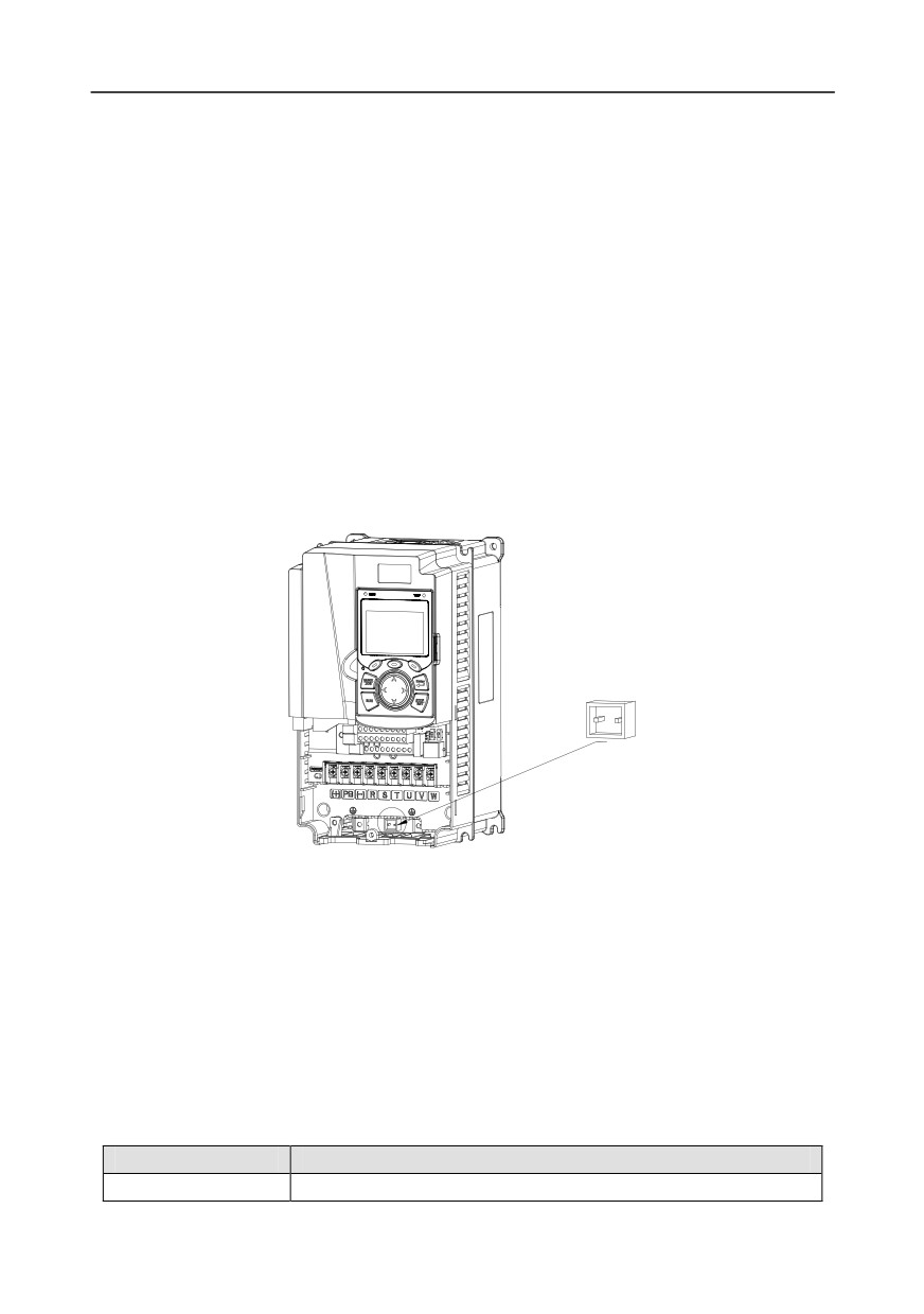
J10 is not connected in factory for inverters of 380V (≤ 110kW). Connect the J10 packaged with the
manual if the requirements of level C3 need to be met;
J10 is connected in factory for inverters of 380V (≥ 132kW), all of which meet the requirements of
level C3.
Note:
Disconnect J10 in the following situations:
1. The EMC filter is applicable to the neutral-grounded grid system. If it is used for the IT grid
system (that is, non-neutral grounded grid system), disconnect J10.
2. If leakage protection occurs during configuration of a residual-current circuit breaker, disconnect
J10.
J10
Note: Do not connect C3 filters in IT power systems.
Interference filters on the input side can reduce the interference of inverters (when used) on the
surrounding devices.
Noise filters on the output side can decrease the radio noise caused by the cables between inverters
and motors and the leakage current of conducting wires.
INVT provides some of the filters for users to choose.
D.7.1 Filter model description
FLT-P 04 045 L-B
A B C
D E F
Field identifier
Field description
A
FLT: Name of the inverter filter series
-332-

Appendix D
Field identifier
Field description
Filter type
B
P: Power input filter
L: Output filter
Voltage class
C
04: AC 3PH 380V (-15%)-440V (+10%)
06: AC 3PH 520V (-15%)-690V (+10%)
3-digit code indicating the rated current. For example, 015 indicates
D
15 A.
Filter performance
E
L: General
H: High-performance
Filter application environment
A: Environment Category I, C1 (EN 61800-3:2004)
F
B: Environment Category I, C2 (EN 61800-3:2004)
C: Environment Category II, C3 (EN 61800-3:2004)
D.7.2 Filters for AC 3PH 380V (-15%)-440V (+10%)
Inverter model
Input filter
Output filter
GD350-1R5G-4
FLT-P04006L-B
FLT-L04006L-B
GD350-2R2G-4
GD350-004G-4
FLT-P04016L-B
FLT-L04016L-B
GD350-5R5G-4
GD350-7R5G-4
FLT-P04032L-B
FLT-L04032L-B
GD350-011G-4
GD350-015G-4
FLT-P04045L-B
FLT-L04045L-B
GD350-018G-4
GD350-022G-4
FLT-P04065L-B
FLT-L04065L-B
GD350-030G-4
GD350-037G-4
FLT-P04100L-B
FLT-L04100L-B
GD350-045G-4
GD350-055G-4
FLT-P04150L-B
FLT-L04150L-B
GD350-075G-4
GD350-090G-4
GD350-110G-4
FLT-P04240L-B
FLT-L04240L-B
GD350-132G-4
GD350-160G-4
GD350-185G-4
FLT-P04400L-B
FLT-L04400L-B
GD350-200G-4
GD350-220G-4
FLT-P04600L-B
FLT-L04600L-B
GD350-250G-4
-333-

Appendix D
Inverter model
Input filter
Output filter
GD350-280G-4
GD350-315G-4
GD350-350G-4
FLT-P04800L-B
FLT-L04800L-B
GD350-400G-4
GD350-450G-4
FLT-P041000L-B
FLT-L041000L-B
GD350-500G-4
Note:
1. The input EMI meets the C2 requirements after an input filter is configured.
2. The preceding table describes external accessories. You need to specify the ones you choose
when purchasing accessories.
D.7.3 Filters for AC 3PH 520V (-15%)-690V (+10%)
Inverter model
Input filter
Output filter
GD350-022G-6
GD350-030G-6
FLT-P06050H-B
FLT-L06050H-B
GD350-037G-6
GD350-045G-6
GD350-055G-6
FLT-P06100H-B
FLT-L06100H-B
GD350-075G-6
GD350-090G-6
GD350-110G-6
GD350-132G-6
FLT-P06200H-B
FLT-L06200H-B
GD350-160G-6
GD350-185G-6
GD350-200G-6
GD350-220G-6
FLT-P06300H-B
FLT-L06300H-B
GD350-250G-6
GD350-280G-6
GD350-315G-6
FLT-P06400H-B
FLT-L06400H-B
GD350-350G-6
GD350-400G-6
GD350-450G-6
GD350-500G-6
FLT-P061000H-B
FLT-P061000H-B
GD350-560G-6
GD350-630G-6
Note:
1. The input EMI meets the C2 requirements after an input filter is configured.
-334-
Appendix D
2. The preceding table describes external accessories. You need to specify the ones you choose
when purchasing accessories.
D.8 Brake system
D.8.1 Brake component selection
When an inverter driving a high-inertia load decelerates or needs to decelerate abruptly, the motor
runs in the power generation state and transmits the load-carrying energy to the DC circuit of the
inverter, causing the bus voltage of the inverter to rise. If the bus voltage exceeds a specific value, the
inverter reports an overvoltage fault. To prevent this from happening, you need to configure brake
components.
The design, installation, commissioning, and operation of the device must be
performed by trained and qualified professionals.
Follow all the "Warning" instructions during the operation. Otherwise, major
physical injuries or property loss may be caused.
Only qualified electricians are allowed to perform the wiring. Otherwise,
damage to the inverter or brake components may be caused.
Read the brake resistor or unit instructions carefully before connecting them
to the inverter.
Connect brake resistors only to the terminals PB and (+), and brake units
only to the terminals (+) and (-). Do not connect them to other terminals.
Otherwise, damage to the brake circuit and inverter and fire may be caused.
Connect the brake components to the inverter according to the wiring
diagram. If the wiring is not properly performed, damage to the inverter or
other devices may be caused.
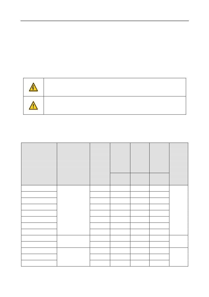
D.8.1.1 Brake units for AC 3PH 380V (-15%)-440V (+10%)
Goodrive350 series inverters of 380 V, 37 kW or lower are equipped with built-in brake units, and
those of 380 V, 45 kW or higher need to be configured with external brake units. Inverters of 45 kW to
110 kW can be configured with optional built-in brake units, and after a built-in brake unit is configured,
the inverter model is added with a suffix "-B", for example, GD350-045G-4-B. Select brake resistors
according to the specific requirements (such as the brake torque and brake usage requirements) on
site.
DissipatedDissipatedDissipated
Resistance
power of
power of
power of
Min.
applicable
brake
brake
brake
allowable
Brake unit
Inverter model
for 100%
resistor
resistor
resistor
brake
model
brake
(kW)
(kW)
(kW)
resistance
torque (Ω)
10% brake
50% brake
80% brake
(Ω)
usage
usage
usage
GD350-1R5G-4
326
0.23
1.1
1.8
170
Built-in brake unit
GD350-2R2G-4
222
0.33
1.7
2.6
130
-335-
Appendix D
DissipatedDissipatedDissipated
Resistance
power of
power of
power of
Min.
applicable
brake
brake
brake
allowable
Brake unit
Inverter model
for 100%
resistor
resistor
resistor
brake
model
brake
(kW)
(kW)
(kW)
resistance
torque (Ω)
10% brake
50% brake
80% brake
(Ω)
usage
usage
usage
GD350-004G-4
122
0.6
3
4.8
80
GD350-5R5G-4
89
0.75
4.1
6.6
60
GD350-7R5G-4
65
1.1
5.6
9
47
GD350-011G-4
44
1.7
8.3
13.2
31
GD350-015G-4
32
2
11
18
23
GD350-018G-4
27
3
14
22
19
GD350-022G-4
22
3
17
26
17
GD350-030G-4
17
5
23
36
17
GD350-037G-4
13
6
28
44
11.7
GD350-045G-4
10
7
34
54
GD350-055G-4
DBU100H-110-4
8
8
41
66
6.4
GD350-075G-4
6.5
11
56
90
GD350-090G-4
5.4
14
68
108
DBU100H-160-4
4.4
GD350-110G-4
4.5
17
83
132
GD350-132G-4
DBU100H-220-4
3.7
20
99
158
3.2
GD350-160G-4
3.1
24
120
192
GD350-185G-4
DBU100H-320-4
2.8
28
139
222
2.2
GD350-200G-4
2.5
30
150
240
GD350-220G-4
2.2
33
165
264
DBU100H-400-4
1.8
GD350-250G-4
2.0
38
188
300
GD350-280G-4
3.6×2
21×2
105×2
168×2
GD350-315G-4
Two sets
3.2×2
24×2
118×2
189×2
2.2×2
GD350-355G-4
DBU100H-320-4
2.8×2
27×2
132×2
210×2
GD350-400G-4
2.4×2
30×2
150×2
240×2
GD350-450G-4
Two sets
2.2×2
34×2
168×2
270×2
1.8×2
GD350-500G-4
DBU100H-400-4
2.0×2
38×2
186×2
300×2
-336-
Appendix D
Note:
1. Select brake resistors according to the resistance and power data provided by our company.
2. The brake resistor may increase the brake torque of the inverter. The preceding table describes
the resistance and power for 100% brake torque, 10% brake usage, 50% brake usage, and 80%
brake usage. You can select the brake system based on the actual operation conditions.
3. When using an external brake unit, set the brake voltage class of the brake unit properly by
referring to the manual of the dynamic brake unit. If the voltage class is set incorrectly, the
inverter may not run properly.
Do not use brake resistors whose resistance is lower than the specified
minimum resistance. Inverters do not provide protection against overcurrent
caused by resistors with low resistance.
In scenarios where brake is frequently implemented, that is, the brake usage
is greater than 10%, you need to select a brake resistor with higher power as
required by the operation conditions according to the preceding table.
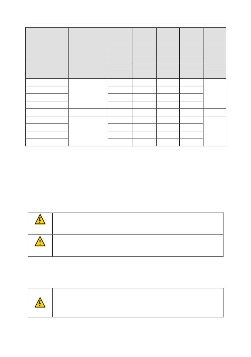
D.8.1.2 Brake units for AC 3PH 520V (-15%)-690V (+10%)
External brake units need to configured for Goodrive350 series inverters of 660 V. Select brake
resistors according to the specific requirements
(such as the brake torque and brake usage
requirements) on site.
Dissipated
DissipatedDissipated
Resistance
power of
power of
power of
Min.
applicable
brake
brake
brake
allowable
Inverter model
Brake unit model
for 100%
resistor
resistor
resistor
brake
brake
(kW)
(kW)
(kW)
resistance
torque (Ω)
10% brake
50% brake
80% brake
(Ω)
usage
usage
usage
GD350-022G-6
55
4
17
27
GD350-030G-6
40.3
5
23
36
GD350-037G-6
32.7
6
28
44
GD350-045G-6
26.9
7
34
54
DBU100H-110-6
10.0
GD350-055G-6
22.0
8
41
66
GD350-075G-6
16.1
11
56
90
GD350-090G-6
13.4
14
68
108
GD350-110G-6
11.0
17
83
132
GD350-132G-6
9.2
20
99
158
DBU100H-160-6
6.9
GD350-160G-6
7.6
24
120
192
GD350-185G-6
6.5
28
139
222
GD350-200G-6
DBU100H-220-6
6.1
30
150
240
5.0
GD350-220G-6
5.5
33
165
264
-337-
Appendix D
Dissipated
DissipatedDissipated
Resistance
power of
power of
power of
Min.
applicable
brake
brake
brake
allowable
Inverter model
Brake unit model
for 100%
resistor
resistor
resistor
brake
brake
(kW)
(kW)
(kW)
resistance
torque (Ω)
10% brake
50% brake
80% brake
(Ω)
usage
usage
usage
GD350-250G-6
4.8
38
188
300
GD350-280G-6
4.3
42
210
336
DBU100H-320-6
3.4
GD350-315G-6
3.8
47
236
378
GD350-355G-6
3.5
53
263
420
GD350-400G-6
DBU100H-400-6
3.0
60
300
480
2.8
GD350-450G-6
5.5×2
34×2
168×2
270×2
GD350-500G-6
Two sets
4.8×2
38×2
188×2
300×2
3.4×2
GD350-560G-6
DBU100H-320-6
4.3×2
42×2
210×2
336×2
GD350-630G-6
3.8×2
47×2
236×2
378×2
Note:
1. Select brake resistors according to the resistance and power data provided by our company.
2. The brake resistor may increase the brake torque of the inverter. The preceding table describes
the resistance and power for 100% brake torque, 10% brake usage, 50% brake usage, and 80%
brake usage. You can select the brake system based on the actual operation conditions.
3. When using an external brake unit, set the brake voltage class of the brake unit properly by
referring to the manual of the dynamic brake unit. If the voltage class is set incorrectly, the
inverter may not run properly.
Do not use brake resistors whose resistance is lower than the specified
minimum resistance. Inverters do not provide protection against overcurrent
caused by resistors with low resistance.
In scenarios where brake is frequently implemented, that is, the brake usage
is greater than 10%, you need to select a brake resistor with higher power as
required by the operation conditions according to the preceding table.
D.8.2 Brake resistor cable selection
Brake resistor cables need to be shielded cables.
D.8.3 Brake resistor installation
All resistors need to be installed in places with good cooling conditions.
The materials near the brake resistor or brake unit must be non-flammable.
The surface temperature of the resistor is high. Air flowing from the resistor is
of hundreds of degrees Celsius. Prevent any materials from coming into
contact with the resistor.
Installation of brake resistors
-338-
Appendix D
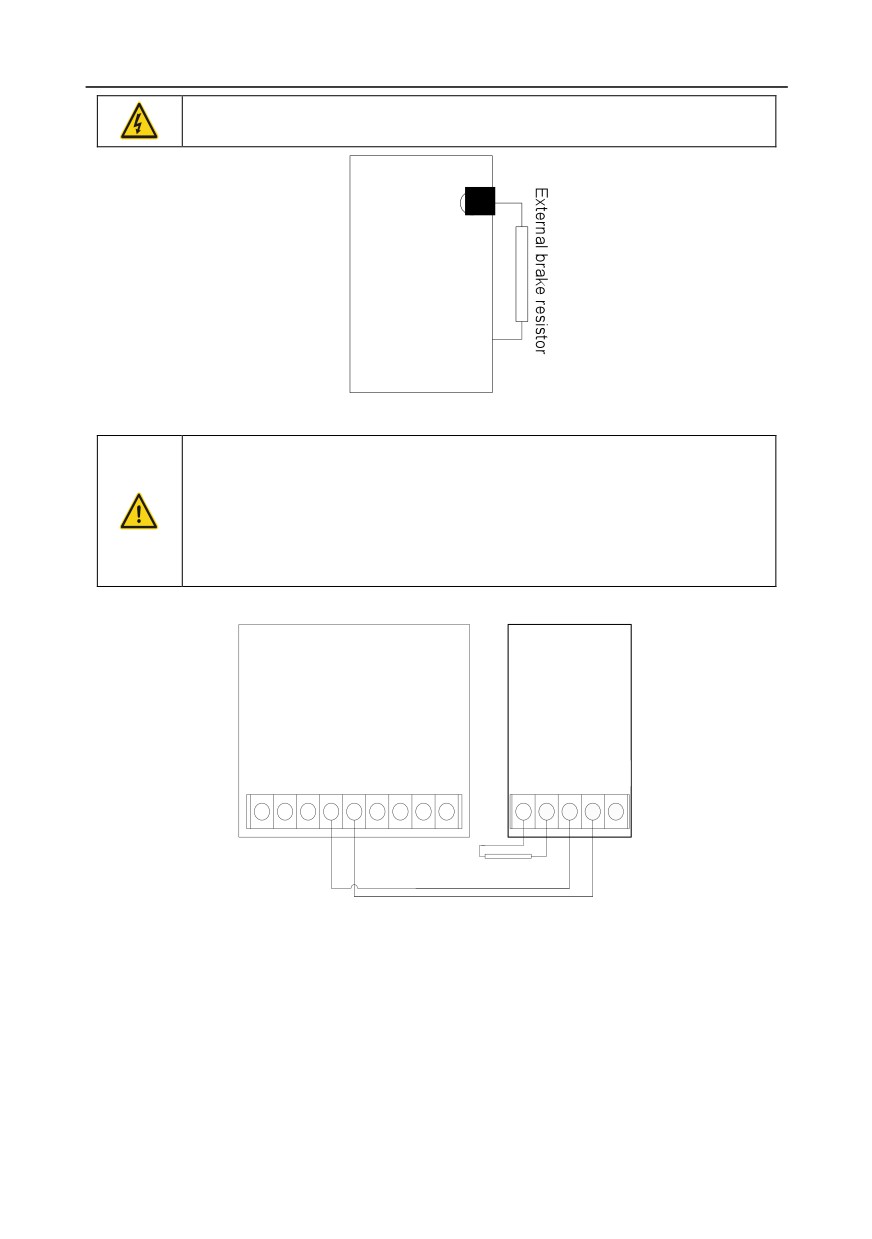
Inverters of 380 V, 37 kW or lower need only external brake resistors.
PB and (+) are the terminals for connecting brake resistors.
Goodrive350
PB
Installation of brake units
All inverters of the 660 V series need external brake units.
(+) and (-) are the terminals for connecting brake units.
The connection cables between the (+) and (-) terminals of an inverter and
those of a brake unit must be shorter than 5 m, and the connection cables
between the BR1 and BR2 terminals of a brake unit and the terminals of a
brake resistor must be shorter than 10 m.
The following figure shows the connection of one inverter to a dynamic brake unit.
DBU
Goodrive350
brake unit
(+)
(-)
DC+
DC-
BR1 BR2
(+)
(-)
PE
+
+
+
+
+
+
+
+
+
+
+
+
+
+
External brake
resistor RB
-339-
Appendix E
Appendix E STO function description
Reference standards: IEC 61508-1, IEC 61508-2, IEC 61508-3, IEC 61508-4, IEC 62061, ISO
13849-1, and IEC 61800-5-2
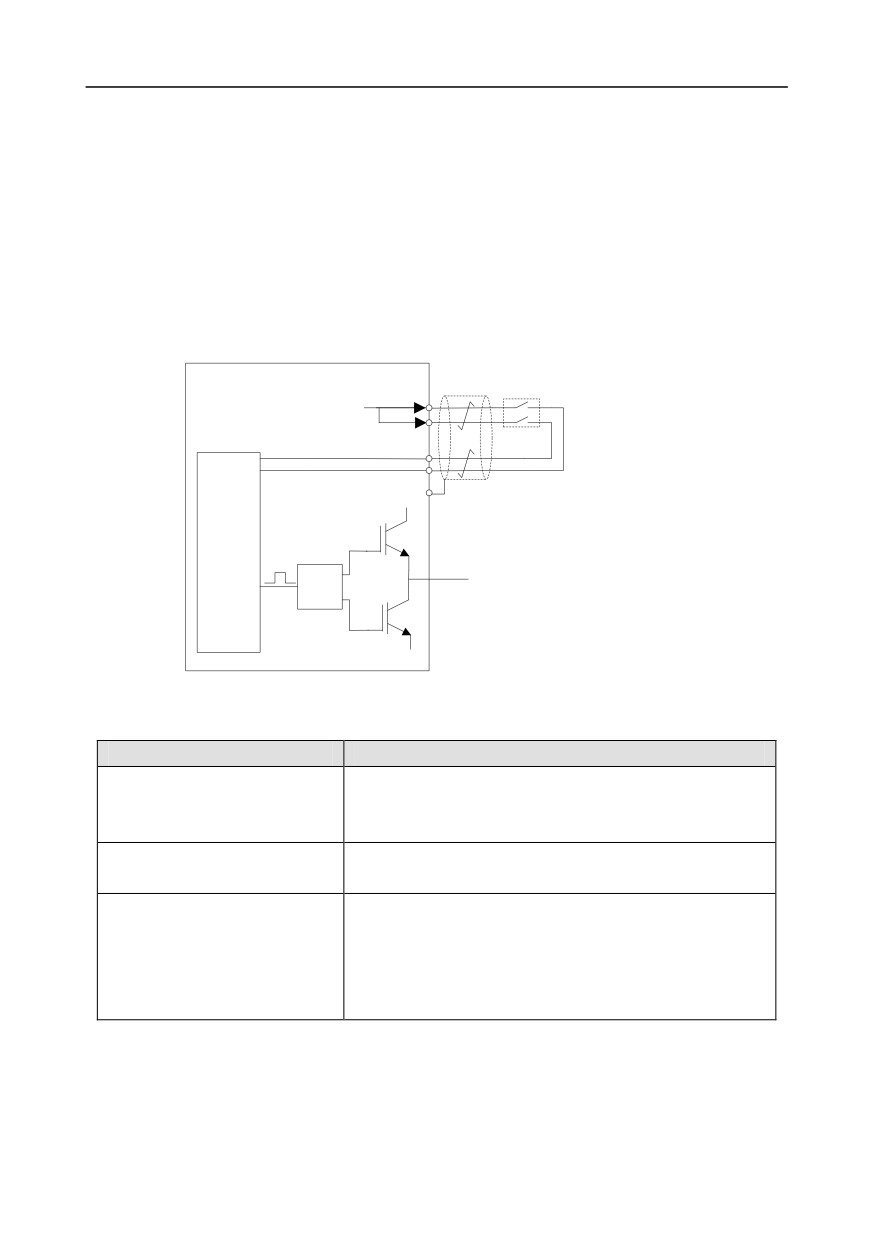
You can enable the safe torque off (STO) function to prevent unexpected startups when the main
power supply of the drive is not switched off. The STO function switches off the drive output by turning
off the drive signals to prevent unexpected startups of the motor (see the following figure). After the
STO function is enabled, you can perform some-time operations (such as non-electrical cleaning in
the lathe industry) and maintain the non-electrical components of the device without switching off the
drive.
Switch, relay, etc.
+24V
H1
H2
COM
UDC+
Control
circuit
PWM+
U/V/W
Drive
circuit
Note:
The contacts of the safety switch must be opened
PWM-
or closed within 250 ms; and the cable that
connects the inverter to the safety switch cannot be
longer than 25 m.
UDC-
E.1 STO function logic table
The following table describes the input states and corresponding faults of the STO function.
STO input state
Corresponding fault
The STO function is triggered, and the drive stops running.
H1 and H2 opened
Fault code:
simultaneously
40: Safe torque off (STO)
H1 and H2 closed
The STOP function is not triggered, and the drive runs
simultaneously
properly.
The STL1, STL2, or STL3 fault occurs.
Fault code:
One of H and H2 opened, and
41: Channel H1 exception (STL1)
the other closed
42: Channel H2 exception (STL2)
43: Channel H1 and H2 exceptions (STL3)
E.2 STO channel delay description
The following table describes the trigger and indication delay of the STO channels.
-340-

Appendix E
STO mode
STO trigger and indication delay1, 2
Trigger delay < 10 ms
STO fault: STL1
Indication delay < 280 ms
Trigger delay < 10 ms
STO fault: STL2
Indication delay < 280 ms
Trigger delay < 10 ms
STO fault: STL3
Indication delay < 280 ms
Trigger delay < 10 ms
STO fault: STO
Indication delay < 100 ms
1. STO function trigger delay: Time interval between trigger the STO function and switching off the
drive output
2. STO instruction delay: Time interval between trigger the STO function and STO output state
indication
E.3 STO function installation checklist
Before installing the STO, check the items described in the following table to ensure that the STO
function can be properly used.
Item
□
Ensure that the drive can be run or stopped randomly during commissioning.
Stop the drive (if it is running), disconnect the input power supply, and isolate the drive
□
from the power cable through the switch.
□
Check the STO circuit connection according to the circuit diagram.
Check whether the shielding layer of the STO input cable is connected to the +24 V
□
reference ground COM.
□
Connect the power supply.
Test the STO function as follows after the motor stops running:
•
If the drive is running, send a stop command to it and wait until the shaft of the
motor stops rotating.
□
•
Activate the STO circuit and send a start command to the drive. Ensure that the
motor does not start.
•
Deactivate the STO circuit.
□
Restart the drive, and check whether the motor is running properly.
Test the STO function as follows when the motor is running:
•
Start the drive. Ensure that the motor is running properly.
•
Activate the STO circuit.
□
•
The drive reports an STO fault (for details, see section 7.5 "Inverter faults and
corresponding solutions"). Ensure that the motor coasts to stop rotating.
•
Deactivate the STO circuit.
□
Restart the drive, and check whether the motor is running properly.
-341-

Appendix F
Appendix F Acronyms and abbreviations
This chapter describes the acronyms and abbreviations of the terms or words that are displayed on
the interfaces of the keypad.
Acronym/
Acronym/
Term/word
Term/word
abbreviation
abbreviation
Accumulated/
Accum
Inverter
Inv
accumulation
Address
Addr
Leakage
Lkge
Amplitude
Amp
Lower limit
LowLim
Bridge
Brdg
Low-frequency
LwFreq
Coefficicent
Coeff
Low-speed
LwSp
Combination
Comb
Master/slave
M/S
Command
Cmd
Operation/operate/operator
Oper
Communication
Comm
Output
Outp
Compensation
Comp
Parameter
Param
Component
Cmpt
Password
Pwd
Consumption
Consume
Position
Pos
Control
Ctrl
Power
Pwr
Current
Cur
Proportional
Prop
Detection/detect
Det
Protect/protection
Prot
Differential
Diff
Quantity
Qty
Digital
Digi
Reference
Ref
Display
Disp
Resistance
Resis
Dynamic
Dyn
Reverse
REV
Eelectromotive force
Emf
Saturation
Satur
Emergency
Emer
Short-circuit
S/C
Error
Err
Source
Src
Factor
Fac
Speed
Spd
Feedback
Fdbk
Spindle
Spdl
Filter/filtering
Filt
Switch
Swt
Forward
FWD
System
SYS
Frequency
Freq
Temperature
Temp
Frequency point
FreqPnt
Terminal
Trml
Friction
Frict
Threshold
Thr
High-speed
HiSp
Torque
Trq
Identification/identity
ID
Upper limit
UpLim
Inductance
Ind
Value
Val
Initial
Init
Version
Ver
Input
Inp
Vibration
Vib
Instance
Inst
Voltage
Volt
Integral
Intg
Voltage point
VoltPnt
Interval
Intvl
-342-
Appendix G
Appendix G Further information
G.1 Product and service queries
Should you have any queries about the product, contact the local INVT office. Provide the model and
offices.
G.2 Feedback on INVT Inverter manuals
personnel or choose Contact Us to obtain contact information.
G.3 Documents on the Internet
You can find manuals and other product documents in the PDF format on the Internet. Visit
-343-