ENC EN500 / EN600 series inverter (ver. 2.0). Service manual - page 6
7 Detailed function specification
7.20 Protective Relevant Function Parameters Group:F19
Range: 0.0~20.0s
Power off restart waiting
F19.00
(0 indicates disabled this
0.0s
time
function)
When the power is off, then power-on, whether this inverter will start
automatically after a waiting time.
When F19.00=0.0s, after the power off then power-on, inverter will not start
automatic. F19.00
0.0s, after the power off then power-on again, if all is ready,
inverter will run automatically with the start method defined by F02.00 after
waiting the time defined by F19.00.
Conditions for repower-on after power-off: it should be in the
running status before power-off; there’s no fault and running signal
maintained when power-on again; there’s no other factors which
Note
affect normal starting.
Range: 0~10
F19.01
Fault self-recovery times
(0 indicates no self-recovery
0
function)
Fault self-recovery interval
F19.02
Range: 0.5~20.0s
5.0s
time
When the inverter is running, because of fluctuation of load, faults may happen in
some case and it will top to output. In order not to stop the operation of equipment,
choosing the recovery functions No alarm, stop in stopping mode. Inverter will
recovery to run with speed-checking restart style, within the setting time, if inverter
cannot run, then fault protection will begin, stop running. No alarm, when the self
recovery times of fault are set to 0, self recovery function stops.
1.When using fault self recovery function, and make sure the
equipment is permitted and inverter do not enter fault.
2.Self recovery function have the effect on power-on terminal
protection, clock fault. overload and over-heated, output
!
short-circuit, short circuit to ground ,and the lack-voltage when
running of fault Protection is disabled.
3.When F19.00 0,open stop and restart function. We can start this
equipment without operators, so be careful to use this function.
Motor overload protection
F19.03
Range: 0~2
2
action selection
When the AC motors is overloaded , this mode of Protection will happen.
195
7 Detailed function specification
0: Alarm, continue operation; It happens with only warning, no motor
overload Protection characteristic (used cautiously, at this time, inverter has nothing to
do with load motor for overload protection;
1: Alarm, Stop according to the stop mode;
2: Fault, Free stop. When it is overloaded , the output of inverter is block , this
AC motor free stop .
Motor overload protection
Range: 20.0~200.0%
F19.04
150.0%
coefficient
(Motor rated current)
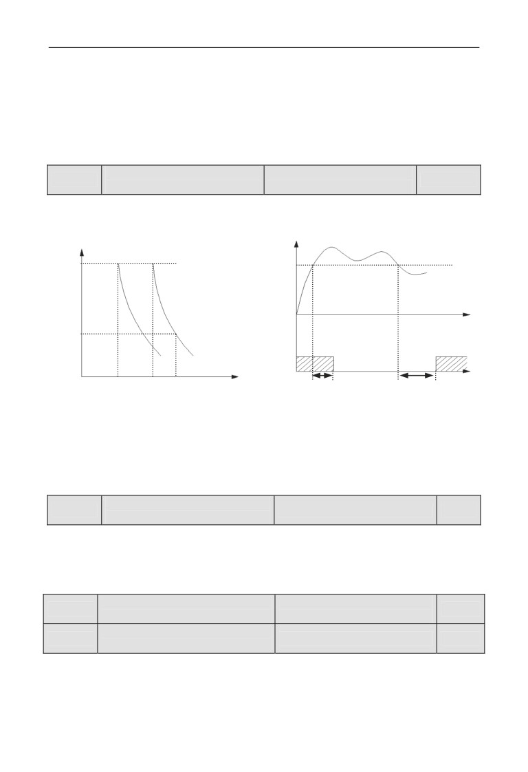
In order to apply effective overload protection to different kinds of motors, the
Max output current of the drive should be adjusted as shown in Fig. 7-44.
Time
Warning level
Output current
60Min
(F19.06)
F19.04=50%
F19.04=100%
Yi
1Min
valid
valid
Current
Time
55%
110%
150%
(G)
F19.07
F19.07
105%
120%
(P)
Fig.7-44 Electronic thermal relay protection Fig.7-45 Overload alarm
This adjustable value can base on the user’s setting. In the same condition, if the
AC motor is overloaded and need the fast protection, then decrease F19.04, or else
increase.
Inverter overload pre-alarm
F19.05
Range: 0,1
0
detection selection
0: Detection all the time. during the working process of inverter , it still
work after detecting overload situation.
1: Enable only constant speed detection. Only the inverter work in a
constant speed mode, it still works after detecting overload situation.
Inverter overload pre-alarm
Range: 20~180%
F19.06
130%
detection level
(Inverter rated current)
Inverter overload pre-alarm
F19.07
Range: 0.0~20.0s
5.0s
delay time
If output current higher parameter F19.06,the set electrical level will go though
delay time of F19.07,open collector will output enabled signal (please refer to
fig7-45 and parameter list F09.00~F09.03).
196
7 Detailed function specification
Motor underload
Range: 0.0~120.0%
F19.08
50.0%
alarm detection level
(Motor rated current)
Motor underload
F19.09
Range:0.1~60.0s
2.0s
alarm detection time
The output current Inverter will lower than Underload alarm detection level
F19.08 (definite the value, comparing to motor rating current ) , and the last time
will over motor underload alarm detection level time F19.09,then Yi will output
underload alarm Signal .
Motor underload
Range: units digit: 0~2
F19.10
00
alarm detection action
tens digit: 0~2
Units digit: detection selection.
0: No detection.
1: The operation has been detected all the time. This detection is enabled
during the running process of inverter.
2: Detect in constant speed mode only. This detection is enabled during the
constant speed mode only.
Tens digit: action selection.
0: when it’s in alarm, continue operation. inverter will only warn when
detecting motor is underload alarm
1: Alarm, Stop according to the stop mode
2: Fault, Free stop .The inverter will detect motor is in underload alarm, and
it will lock PWM output, the motor will stop with free rotation.
Range: units digit: 0,1
Input & output phase loss,
tens digit: 0,1
F19.11
short circuit detection
1111
hundreds digit: 0,1
action
thousands digit: 0,1
Units digit: input phase failure protect
0: No detection.
1: Fault, Free stop .When inverter detect that the input is lacked one phase,
alarm in input lacked, alarm, and free stop.
Tens digit: output phase failure protection
0 : No detection.
1:Fault, Free stop .When inverter detect that the output is lacked one phase,
alarm in input lacked, then Free stop.
Hundreds digit: power-on will detect Short circuit protection.
0: No detection.
1: Fault, Free stop. When inverter is power-on, the output to earth is
short-circuiting. At this time, the fault of short-circuiting to earth while power on
is alarmed, the inverter freely stops.
Thousands digit: The detection to earth Short circuit protection in the running
197
7 Detailed function specification
mode.
0: No detection.
1: Fault, Free stop. When inverter is power-on, the output to earth is
short-circuiting during the running process. At this time, the fault of
short-circuiting to earth while running is alarmed, the inverter freely stops.
F19.12
Overvoltage stall selection
Range: 0,1
1
0: Disabled.
1: Enabled
Overvoltage stall protection
F19.13
Range: 120~150%
125%
voltage
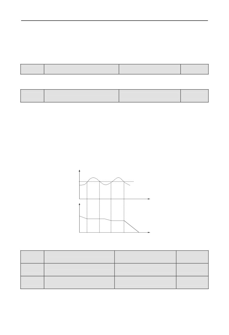
During deceleration, the motor’s decelerate rate may be lower than that of drive’s
output frequency due to the load inertia. At this time, the motor will feed the
energy back to the drive, resulting in the voltage rise on the drive's DC bus. If no
measures taken, the drive will trip due to over voltage.
During the deceleration, the drive detects the bus voltage and compares it with the
over voltage point at stall defined by F19.13. If the bus voltage exceeds the stall
over-voltage point, the output frequency of the inverter will stop decreasing.
When the bus voltage become lower than the point, then run slowly, as shown in
Fig. 7-46.
Overvoltage
point at stall
Time
Output freq.
Time
Fig. 7-46 Over-voltage at stall
Automatic current limit
F19.14
Range: 110~230%
170%
level
Frequency decline rate of
F19.15
Range: 0.00~99.99Hz/s
10.00Hz/s
automatic current limit
Automatic current limit
F19.16
Range: 0,1
0
action selection
0: Constant speed disabled.
1: Constant speed enabled.
Auto current limiting function is used to limit the load current smaller than the
198
7 Detailed function specification
value defined by F19.14 in real time. Therefore the drive will not trip due to surge
over-current. This function is especially useful for the applications with big load
inertia or big change of load.
F19.14 defines the threshold of auto current limiting. It is a percentage of the
drive’s rated current.
F19.15 defines the decrease rate of output frequency when the drive is in auto
current limiting status.
If F19.15 is set too small, overload fault may occur. If it is set too big, the
frequency will change too sharply and therefore, the drive may be in generating
status for longtime, which may result in overvoltage protection.
Auto current limiting function is always active in Acc or Dec process. Whether
the function is active in constant speed operating process is decided by F19.16.
F19.16=0 Auto current limiting function is disabled inconstant speed operating
process;
F19.16=1 Auto current limiting function is enabled inconstant speed operating
process;
In auto current limiting process, the drive’s output frequency may change;
therefore, it is recommended not to enable the function when the drive’s output
frequency is required stable.
F19.17
Rapid current-limiting coefficient
Range: 150%~250%
230%
The rapid current limit function can reduce the AC drive's over-current faults at
maximum, guaranteeing uninterrupted running of the AC drive. If the AC drive is
in a rapid current limit state for a long time, the AC drive may be overheated or
overloaded for further protection.
The lower the setting of the F19.17, the more sensitive the rapid current limit is.
When the F19.17 equals 250%, the rapid current limit function is invalid.
Motor run section selection
F19.18
Range: 0,1
0
when instant power off
0: disabled
1: enabled
Frequency droop rate when
F19.19
Range: 0.00~99.99Hz/s
10.00Hz/s
instant power off
Voltage rebound estimate
F19.20
Range: 0.00~10.00s
0.10s
time when instant power off
Action estimate voltage
F19.21
Range: 60~100%
80%
when instant power off
Allowed the longest off time
F19.22
Range: 0.30~5.00s
2.00s
when instant power off
199
7 Detailed function specification
Bus voltage
F19.20
F19.21
Time
Run freq.
DecelerationAcceleration
Time
time
time
Run freq
F19.22
Time
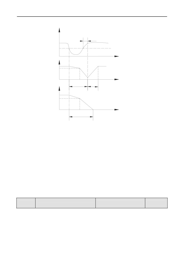
Fig 7-47 AC drive action diagram upon instantaneous power failure
Upon instantaneous power failure or sudden voltage dip, the DC bus voltage of
the AC drive reduces. This function enables the AC drive to compensate the DC
bus voltage reduction with the load feedback energy by reducing the output
frequency so as to keep the AC drive running continuously.
If F19.18 = 1, upon instantaneous power failure or sudden voltage dip, the AC
drive decelerates. Once the bus voltage resumes to normal, the AC drive
accelerates to the set frequency. If the bus voltage remains normal for the time
exceeding the value set inF19.20, it is considered that the bus voltage resumes to
normal.
When instantaneous power failure happens, if the time is exceed the time of
F19.22 definite, inverter No alarm, stop in stopping mode Free stop.
Terminal external device
F19.23
Range: 0~2
2
fault action selection
0: Alarm, continue operation .When inverter checked that Terminal of the
external is no alarm, stop in stopping mode enabled, it will alarm, then run
continue. Under this mode, the inverter will do nothing with Terminal of the
external in No alarm, stop in stopping mode, so please cautiously use.
1: Alarm, Stop according to the stop mode. When Inverter detect terminal
outside fault is enabled, alarm, and then press Stop in stopping mode.
2: Fault, Free stop .When inverter detect terminal external fault is enabled,
200
7 Detailed function specification
alarm for external equipment fault, and free stop.
Power on terminal protection
F19.24
Range: 0,1
0
selection
0: Disabled.
1: Enabled.
When setting power down and then restart function is enabled, this function is
disabled. When the running command channel is terminal command, and when
power-on and detection run the command is enabled, it will get terminal
protection with faults, this function only is enabled for terminal FWD/REV
function.
F19.25
Provide lost detection value
Range: 0~100%
0%
F19.26
Provide lost detection time
Range: 0.0~20.0s
0.5s
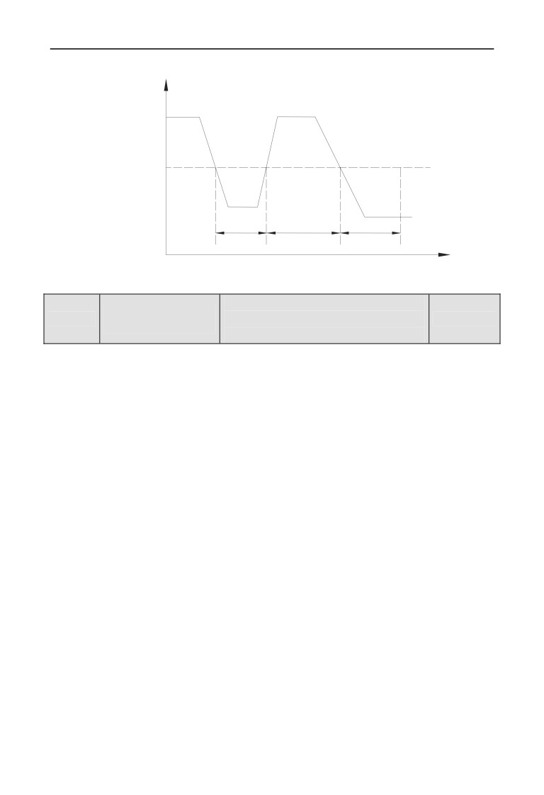
When setting PID is lower than F19.25 definition continuous(setting the Max. as
base), and the constant time is over than the time that F19.26 definition detected,
then PID setting will lost, inverter will run base on F19.31 Units place
set.PID
loss detection show on fig 7-48.
F19.27
Feedback lost detection value
Range: 0~100%
12%
F19.28
Feedback lost detection time
Range: 0.0~20.0s
0.5s
When the feedback value of PID is lower than F19.27 definite(setting the input as
base, and the constant time is over than the time that F19.28 definition detected,
then PID setting will lost.
Inverter will run base on F19.31 Tens place set.PID loss detection show on fig
7-48.
Deviation magnitude
F19.29
Range: 0~100%
50%
abnormal detection value
Deviation magnitude
F19.30
Range: 0.0~20.0s
0.5s
abnormal detection time
When the Error amount of PID is higher than F19.29 definite(setting the input as
base, and the constant time is over than the time that F19.30 definition detected,
then PID setting will lost. inverter will run base on F19.31 hundred’s place
set.PID loss detection show on fig 7-48.
201
7 Detailed function specification
Close loop value
(setting, feedback, error value)
The detection
value
Less than detection timeNo detection
more than detection time
No alarm when detection
Failure alarm when detection
Time
Fig. 7-48 Closed loop detection timing diagram
Range: units digit: 0~3
Protection action
F19.31
tens digit: 0~3
000
selection 1
hundreds digit: 0~3
This parameter definite the Internal PID controls the action selection of the setting
loss and the fault Error amount. When it’s set as 0 OR 1, inverter will have no
response. And with no protection selection, users should set this parameter basing
on the actual applications.
Units digit: setting PID lost motion detection.
0: no detection.
1: Alarm, continue operation
2: Alarm, Stop according to the stop mode
3: Fault, Free stop.
Tens digit: PID feedback for lost motion detection.
0: no detection.
1: Alarm, continue operation.
2: Alarm, Stop according to the stop mode.
3: Fault, Free stop.
Hundreds digit: The amount of error fault for PID detection operation
0: no detection.
1: Alarm, continue operation
2: Alarm, Stop according to the stop mode
3: Fault, Free stop.
202
7 Detailed function specification
Range: units digit: 0~2
Protection action
tens digit: 0~2
F19.32
1200
selection 2
hundreds digit: 0~2
thousands digit: 0,1
This parameter definite the communication fault, E2PROM fault, Contactor fault
and lack-voltage when it’s in No alarm, stop in stopping mode for the action
selection of inverter. When it’s set as 0, during the fault situation, inverter will
only alarm. And with no protection selection, users should set this parameter
basing on the actual applications.
Units digit: communication fault action, including communication replay and
fault.
0: Alarm, continue operation
1: Alarm, Stop according to the stop mode
2: Fault, free stop .
Tens digit: E2PROM fault action selection.
0: Alarm, continue operation
1: Alarm, stop according to the stop mode
2: Fault, free stop.
Hundreds digit: Contactor fault action selection.
0: Alarm, continue operation
1: Alarm, stop according to the stop mode
2: Fault, free stop.
Thousands digit: running lack-Voltage fault display action selection.
0: no detection.
1: Fault, free stop.
F19.33
Reserved
F19.34
Reserved
Fault indication and clock
Range: units digit: 0,1
F19.35
00
during the period of recovery
tens digit: 0,1
Units digit: During automatic reset of fault display selection.
0: Action. During automatic reset, Yi and Relay of will update display the
Signal based on the internal state.
1: No action. During automatic reset, Yi and Relay display Signal No action.
Tens digit: Lock function selection, to realize display before power-off.
0: disabled.
1: enabled. When this function is enabled, if the inverter shows the fault
before the last time power down, then the inverter will display the fault last time
203
7 Detailed function specification
fault state, make sure that users will know about the inverter’s potential faults.
Continuous run frequency
F19.36
Range: 0~3
0
selection when alarm
This parameter defines the run frequency when users choose “Alarm, continues to
run” for the inverter’s failure.
0: running at the current setting frequency.
1: running at the upper limiting frequency.
2: running at the lower limit frequency.
3: running at the fault Alternate frequency.
Abnormal standby
Range: 0.00Hz~upper limit
F19.37
10.00Hz
frequency
frequency
This parameter definite the alternative running frequency when inverter fault ,
user can use it along with parameterF19.36.
Disconnection testing
Range: 0.0~8.0s
F19.38
0.0s
time of encoder
(No detection while at 0)
When the inverter runs with the closed-loop vector mode,the detection starts
while the run frequency is higher than 1Hz, when the A,B-phase signal of the
encoder continues for the time set in F19.38, and no feedback has been received,
then the inverter alarms the fault of E-37 and freely stop.
Overspeed detection
Range: 0.0~120.0%
F19.39
120.0%
value
(equals upper limit frequency)
Overspeed detection
Range: 0.00~20.00s
F19.40
0.00s
time
(no detection while at 0)
Under the open-loop or the closed-loop vector mode, when it was detected that the
motor rotational speed is higher than the setting value of F19.39, and after the
continue time of F19.40’s setting value, the inverter alarms fault of E-38 and
freely stop. No detection when F19.40 equals 0, but detection is still available
when F19.39 equals 0.
Detection value of too
Range: 0.0~50.0%
F19.41
10.0%
large speed deviation
(equals upper limit frequency)
Detection time of too
Range: 0.00~20.00s
F19.42
0.00s
large speed deviation
(no detection while at 0)
Under the open-loop or the closed-loop vector running mode, when it was
detected that the difference of motor rotational speed and setting rotational speed
equals the setting value of F19.41, and after the continue time of F19.42’s setting
value, the inverter alarms fault of E-39 and freely stop. No detection when F19.42
equals 0, but detection is still available when F19.41 equals 0.
204
7 Detailed function specification
Overvoltage suppression
F19.43
Range: 0.0~100.0%
90.0%
coefficient
The bigger value of F19.43, the more obvious the suppression will be, but the load
response will be slow, the parameter is available when F00.24=1 or 2.
When the load fluctuation is strong, the devices like crusher, punch, pipe file
machine and the equipment with clutch will be over-voltage easily, so increasing
the parameter is needed.
F19.44
Reserved
205
7 Detailed function specification
7.21 Internal Virtual Input Output Node Parameter Group: F20
F20.00
Virtual input VDI1 function selection
Range: 0~90
0
F20.01
Virtual input VDI2 function selection
Range: 0~90
0
F20.02
Virtual input VDI3 function selection
Range: 0~90
0
F20.03
Virtual input VDI4 function selection
Range: 0~90
0
F20.04
Virtual input VDI5 function selection
Range: 0~90
0
VDI1 to VDI5 have the same functions as Xi terminals on the control board and
can be used for digital input. For more details, see description of F08.18 to F08.25.
The realization of the function set by internal virtual terminal must be based on
the available terminal function.
F20.05
Virtual output VDO1 function selection
Range: 0~60
0
F20.06
Virtual output VDO2 function selection
Range: 0~60
0
F20.07
Virtual output VDO3 function selection
Range: 0~60
0
F20.08
Virtual output VDO4 function selection
Range: 0~60
0
F20.09
Virtual output VDO5 function selection
Range: 0~60
0
VDO functions are similar to the Yi functions on the control board. The VDO can
be used together with VDIx to implement some simple logic control.
If VDO function is set to non-0, the function setting and use of VDOx are the
same as the output of parameter of Yi. Please refer to descriptions in group F09.
Virtual output VDO1 open
F20.10
Range: 0.00~600.00s
0.00s
delay time
Virtual output VDO2 open
F20.11
Range: 0.00~600.00s
0.00s
delay time
Virtual output VDO3 open
F20.12
Range: 0.00~600.00s
0.00s
delay time
Virtual output VDO4 open
F20.13
Range: 0.00~600.00s
0.00s
delay time
Virtual output VDO5 open
F20.14
Range: 0.00~600.00s
0.00s
delay time
Virtual output VDO1 close
F20.15
Range: 0.00~600.00s
0.00s
delay time
Virtual output VDO2 close
F20.16
Range: 0.00~600.00s
0.00s
delay time
Virtual output VDO3 close
F20.17
Range: 0.00~600.00s
0.00s
delay time
Virtual output VDO4 close
F20.18
Range: 0.00~600.00s
0.00s
delay time
206
7 Detailed function specification
Virtual output VDO5 close
F20.19
Range: 0.00~600.00s
0.00s
delay time
F20.10~ F20.19 definite the time of open up and shut down terminal
VDO1~VDO5 definite is the delay time of internal level from open up to shut
down.
F20.20
Virtual input VDI enable control
Range: 00~FF
00
Parameter F20.20 is to control VDI1~VDI5 is enable. F20.20(BIT0-BIT4) is
according to the enable unit VDI1~VDI5,0 stands for disabled , 1 stands for
enable. The relations are below:
tens
units
BIT0: VDI1 enable control unit
BIT1: VDI2 enable control unit
BIT2: VDI3 enable control unit
BIT3: VDI4 enable control unit
BIT0:VDI5 enable control unit
F20.21
Virtual input VDI status digital setup
Range: 00~FF
00
Virtual input terminal VDI state is determined by the VDI F20.21 definite virtual
input VDI state Digital and virtual output terminal VDO state, the relation
between them is logical OR.
Parameter F20.21 BIT0-BIT4 is according to VDI1-VDI5 state, 0 stands for
disabled state, 1 stands for enabled state.
F20.22
Virtual input: output connection
Range: 00~FF
00
Bit0 : The connection of VDI1 and VDO1
0 : positive logic.
1 : negative logic.
Bit1 : The connection of VDI2 and VDO2
0 : positive logic.
1 : negative logic.
Bit2 : The connection of VDI3 and VDO3
0 : positive logic.
1 : negative logic.
Bit3 : The connection of VDI4 and VDO4
0 : positive logic.
1 : negative logic.
Bit4 : The connection of VDI5 and VDO5
207
7 Detailed function specification
0 : positive logic.
1 : negative logic.
Parameter F20.22 definite logical relation if the virtual output terminal, Bit0~Bit4
is according to logical relation setting of VDI1~VDI5 and VDO1~VDO5 , 0
stands for positive logic , 1 stands for negative logic.
Parameter F20.21 definition VDI state , the Digital setting will not
influence by F20.22.
Note
208
7 Detailed function specification
7.22 Reserved parameter group 2:F21
F21.00
~
Reserved
F21.21
7.23 Reserved parameter group 3:F22
F22.00
~
Reserved
F22.17
7.24 Reserved parameter group 4:F23
F23.00
~
Reserved
F23.17
7.25 Reserved parameter group 5:F24
F24.00
~
Reserved
F24.13
209
7 Detailed function specification
7.26 User Definition Display Parameter Group: F25
F25.00
User function code 1
Range: F00.00~F25.xx
25.00
F25.01
User function code 2
Range: F00.00~F25.xx
25.00
F25.02
User function code 3
Range: F00.00~F25.xx
25.00
F25.03
User function code 4
Range: F00.00~F25.xx
25.00
F25.04
User function code 5
Range: F00.00~F25.xx
25.00
F25.05
User function code 6
Range: F00.00~F25.xx
25.00
F25.06
User function code 7
Range: F00.00~F25.xx
25.00
F25.07
User function code 8
Range: F00.00~F25.xx
25.00
F25.08
User function code 9
Range: F00.00~F25.xx
25.00
F25.09
User function code 10
Range: F00.00~F25.xx
25.00
F25.10
User function code 11
Range: F00.00~F25.xx
25.00
F25.11
User function code 12
Range: F00.00~F25.xx
25.00
F25.12
User function code 13
Range: F00.00~F25.xx
25.00
F25.13
User function code 14
Range: F00.00~F25.xx
25.00
F25.14
User function code 15
Range: F00.00~F25.xx
25.00
F25.15
User function code 16
Range: F00.00~F25.xx
25.00
F25.16
User function code 17
Range: F00.00~F25.xx
25.00
F25.17
User function code 18
Range: F00.00~F25.xx
25.00
F25.18
User function code 19
Range: F00.00~F25.xx
25.00
F25.19
User function code 20
Range: F00.00~F25.xx
25.00
F25.20
User function code21
Range: F00.00~F25.xx
25.00
F25.21
User function code 22
Range: F00.00~F25.xx
25.00
F25.22
User function code 23
Range: F00.00~F25.xx
25.00
F25.23
User function code 24
Range: F00.00~F25.xx
25.00
F25.24
User function code 25
Range: F00.00~F25.xx
25.00
F25.25
User function code 26
Range: F00.00~F25.xx
25.00
F25.26
User function code 27
Range: F00.00~F25.xx
25.00
210

7 Detailed function specification
F25.27
User function code 28
Range: F00.00~F25.xx
25.00
F25.28
User function code 29
Range: F00.00~F25.xx
25.00
F25.29
User function code 30
Range: F00.00~F25.xx
25.00
This parameter is the User-defined parameter, user can choose the at most 30 from
F0 to F30 that are reflect into F25, in order to check and alter more convenient.
Use F25.00 setting the first function code parameter that users plan to. then use
F25.01 setting the second function code parameter that users plan to, so after the
maximum 30 User-defined parameter that can define is finished, then setting
F00.00=3(user list view, press
.If users want to drop out user-defined
parameter mode, setting F00.00 3,then press.
For example: user plan to set three User-defined parameter :F02.01,F03.02 和
F04.00 , following the steps below :
⑴Use F25.00 to set the first function code parameter02.01, press
;
⑵Use F25.01 to set the second function code parameter03.02, press
;
⑶Use F25.02 to set the third function code parameter04.00, press
⑷Set F00.00=3(user list view, press
).
After the setting is finished , if users do not change F00.00 function code, when
enter function code display state, the operation panel will display
F00.00,F02.01,F03.02 and F04.00 only, if the user do not want to display
User-defined parameter, setting F00.00 to the display expected mode.
1. xx represent function code.
2.F25.xx represent no reflection.
Note
When the setting function parameter is not available into the
range of EN500/EN600 permit, setting the User-defined parameter
Note
will not make effective.
211
7 Detailed function specification
7.27 Fault Record Function Parameter Group: F26
F26.00
The last fault record
Range: 0~50
0
F26.01
The last two fault records
Range: 0~50
0
F26.02
The last three fault records
Range: 0~50
0
F26.03
The last four fault records
Range: 0~50
0
0:No fault.
1~26: E-01~E-26 fault.
27~29: Reserved.
30~39: E-30~E-39 fault.
40~50: Reserved.
F26.00~F26.03 definite the four times previous four code of faults and the two
times previous fault for the voltage, current terminal and etc of inverter , users
base on fault code and refer to fault function& fault handle process, then getting
the results for different types of fault and reasons.
Setup frequency at the
Range:0.00Hz~upper limit
F26.04
0.00Hz
last one fault
frequency
Output frequency at the
Range:0.00Hz~upper limit
F26.05
0.00Hz
last one fault
frequency
Output current at the last
F26.06
Range: 0.0~6553.5A
0.0A
one fault
DC bus voltage at the last
F26.07
Range: 0.0~6553.5V
0.0V
one fault
Module temperature at
F26.08
Range: 0~125℃
0℃
the last one fault
Input terminal status at
F26.09
0
the last one fault
Accumulated run time at
F26.10
Range: 0~65535min
0min
the last one fault
Setup frequency at the
Range:0.00Hz~upper limit
F26.11
0.00Hz
last two fault
frequency
Output frequency at the
Range:0.00Hz~upper limit
F26.12
0.00Hz
last two fault
frequency
Output current at the last
F26.13
Range: 0.0~6553.5A
0.0A
two fault
DC busbar voltage at the
F26.14
Range: 0.0~6553.5V
0.0V
last two fault
Module temperature at the
F26.15
Range: 0~125℃
0℃
last two fault
Input terminal status at
F26.16
0
the last two fault
212
7 Detailed function specification
Accumulated run time at
F26.17
Range: 0~65535min
0min
the last two fault
F26.04~F26.17 record the running state of fault for the first and second time
before, when Input terminal state at the fault, the terminal state is the whole
terminal state after the time delay, including the standard input terminal state and
expanded input terminal state .When Virtual terminal communication is set as the
terminal panel point , the standard Input terminal state is determined by the actual
physical input terminal and Virtual terminal communication .please refer to the
details of the Input terminal state :
Bit0:X1(Standard input terminal 1). 1: valid;0: invalid
Bit1:X2(Standard input terminal 2). 1: valid;0: invalid
Bit2:X3(Standard input terminal 3). 1: valid;0: invalid
Bit3:X4(Standard input terminal 4). 1: valid;0: invalid
Bit4:X5(Standard input terminal 5). 1: valid;0: invalid
Bit5:X6(Standard input terminal 6). 1: valid;0: invalid
Bit6:X7(Standard input terminal 7). 1: valid;0: invalid
Bit7:X8(Standard input terminal 8). 1: valid;0: invalid
Bit8:EX1(Extended input terminal 1). 1: valid;0: invalid
Bit9:EX2(Extended input terminal 2). 1: valid;0: invalid
Bit10:EX3(Extended input terminal 3). 1: valid;0: invalid
Bit11:EX4(Extended input terminal 4). 1: valid;0: invalid
Bit12:EX5(Extended input terminal 5). 1: valid;0: invalid
BIT13:EX6(Extended input terminal 6). 1: valid;0: invalid
213
7 Detailed function specification
7.28 Password and Manufacturer Function Parameter Group:
F27
F27.00
User password
Range: 00000~65535
00000
User password setting function is used for preventing unauthorized persons from
checking and modifying the functional parameters.
Set F27.00 to 00000 if the user password function is unnecessary.
If user password function is necessary, input a 5-digitnone-zero figure, and press
to confirm. The password is effective at once.
To change the password:
Press
and input the primary password, selectF27.00 (F27.00=00000 at the
moment), then input new password and press
to confirm. The password is
effective at once.
To cancel the password:
Press
into the state of verification, and enter the original correct 5-digit
password into the state of parameter editing, then select F27.00 (F27.00=00000 at
the moment), and directly press
to confirm, the password can be canceled
Please memorize the password. Seeking advice from manufacturer
in case it is lost.
Note
F27.01
Manufacturer password
Range: 00000~65535
00000
Factory setting function, the user can't modify.
214
8 Troubleshooting
8 Troubleshooting
8.1 Failure and countermeasure
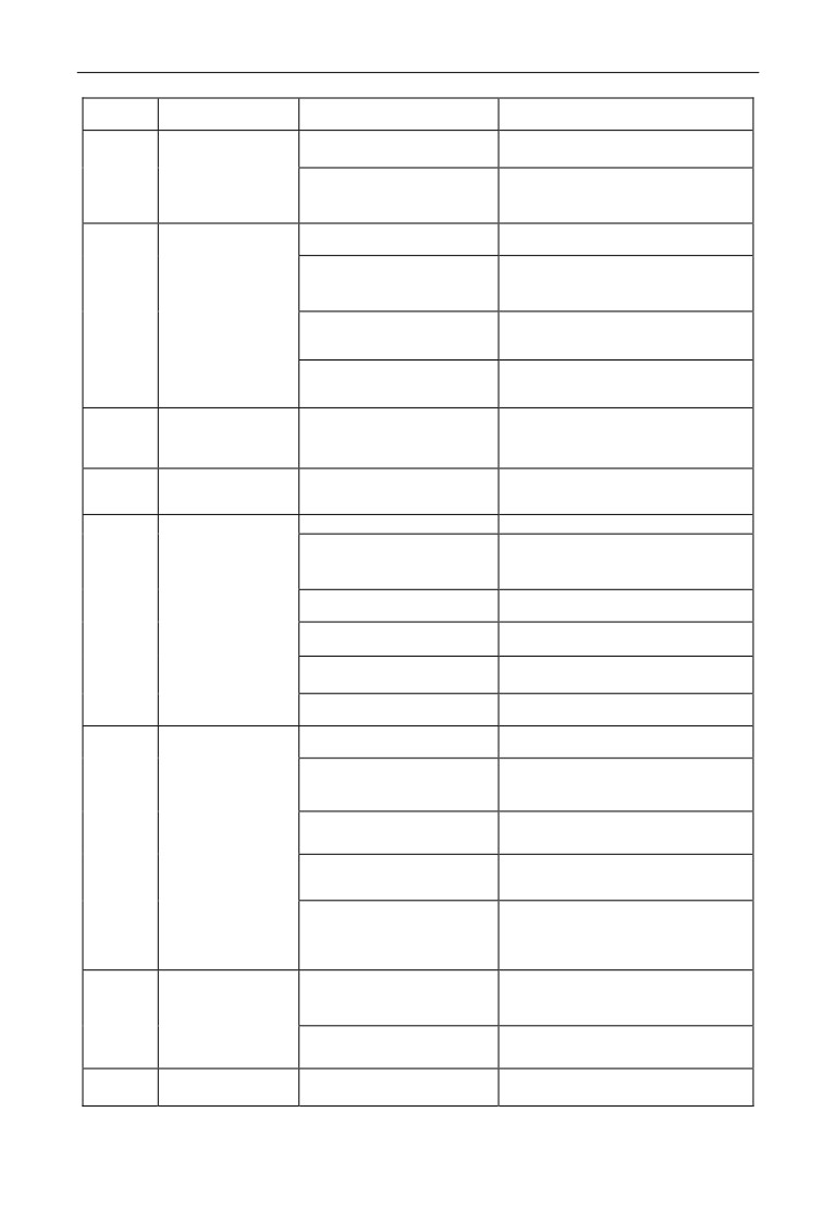
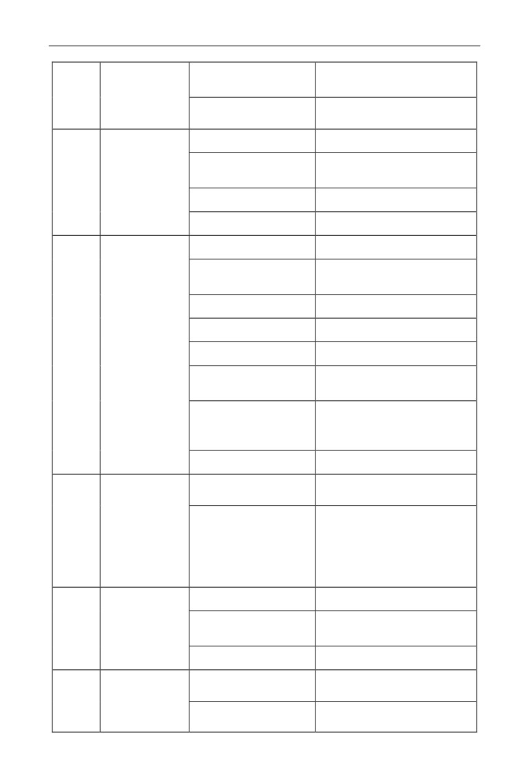
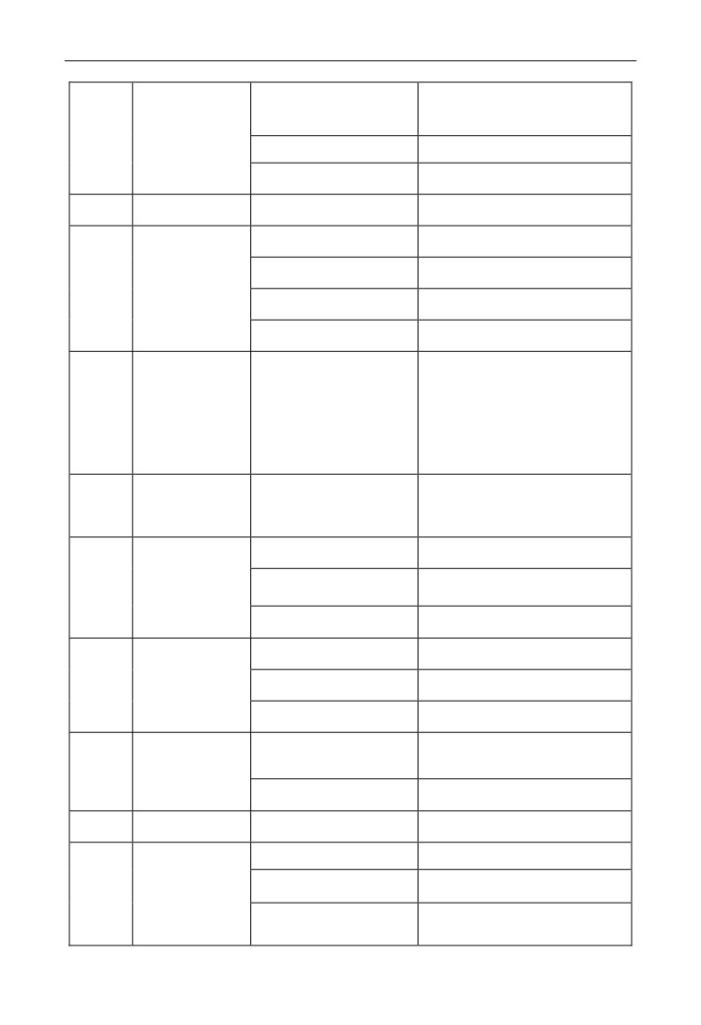
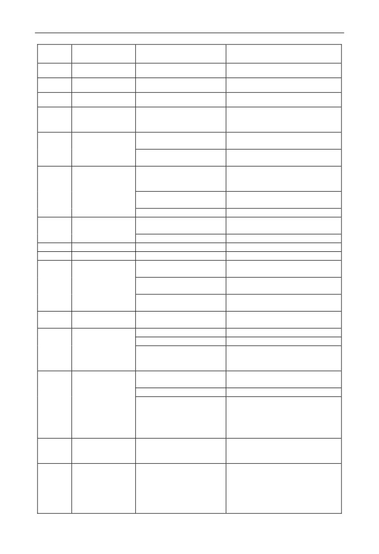
Possible failure types in EN500/EN600 are shown in Table 8-1, the fault types
including fault and alarm two kinds. Such as if inverter fault display E-XX, while
the corresponding alarm is displayed in A-XX. Once the inverter failure , fault types
are stored in the F26 fault recording parameter group, and if alarm, alarm status has
been revealed, until the alarm source release, alarm status are not logged to the F26
parameter group. Some failure code is reserved for intelligent automatic diagnosis
function which will be executed continuously in future. When failure takes place in
the inverter, the user should check according to note of these table first and record
failure phenomena detailedly. Please contact our after-sale service and technical
support Department or agent in your local place when technical service is needed.
Table 8-1 Failure type and the countermeasure
Failure
Failure type
Possible reason
Countermeasure
code
Accelerating time is too
Prolong accelerating time
short
Adjust V/F curve setting,adjust
Improper V/F curve
manual torque boost or change to
automatic torque boost
Overcurrent during
Restart rotating motor
Set speed checking restart function
E-01
accelerating
process
Low power source voltage
Check input power supply
Too small power of the
Choose inverter with high-power
inverter
Output phase lose under
Check whether the motor wiring is
vector control
in good condition
Decelerating time is too
Prolong decelerating time
short
Increase braking power of external
Overcurrent during
Have potential energy load
energy consumption braking
E-02
decelerating
or big Inertia load
subassembly
process
Power of inverter is a bit
Choose inverter with high-power
small
Load change suddenly or
Check or reduce saltation of the
have unwonted phenomena
load
Acc./Dec. time is set to too
Prolong accelerating /decelerating
Overcurrent during
short
time properly
E-03
constant
speed
process
low power source voltage
Check input power supply
Power of inverter is a bit
Choose inverter with high-power
small
E-04
Overvoltage
Unwonted input voltage
Check input power supply
during accelerating
process
Acc. time is set to too short
Prolong accelerating time properly
215
8 Troubleshooting
Restart rotating motor
Set speed checking restart function
Decelerating time is too
Prolong decelerating time
Overvoltage during
short
E-05
decelerating
Increase braking power of external
Have potential energy load
process
energy consumption braking
or big inertia load
subassembly
Unwonted input voltage
Check input power supply
Acc/Dec time is set to too
Prolong accelerating decelerating
Overvoltage during
short
time properly
E-06
constant
speed
Input voltage change
process
Assemble reactor
abnormally
Use energy consumption
Load inertia is a bit big
subassembly
Inverter control
Check input power supply or look
E-07
power supply
Unwonted input voltage
for service
overvoltage
Low-voltage when
E-08
Input voltage is too low
Check the input voltage
running
Acc time is set to too short Prolong accelerating time
DC injection braking is too
Reduce DC injection braking
big
current,prolong braking time
Inverter overload
improper V/F curve
Adjust V/F curve and torque boost
E-09
protection
Restart rotating motor
Set speed checking restart function
power source voltage is too
check power source voltage
low
Load is too big
Choose inverter with high-power
Improper V/F curve
Adjust V/F curve and torque boost
Power source voltage is too
check power source voltage
low
General motor run at low
Can choose frequency conversion
E-10
Motor overload
speed with big load
motor for long time low speed run
(A-10)
protection
Motor overload protection
to set motor overload protection
factor set incorrectly
factor correctly
Motor blocked up or load
change too suddenly and
Check the load
quickly
The operating current of
Confirm whether the parameters
inverter less than underload
F19.08,
F19.09 setting
are
E-11
Motor underload
threshold
reasonable
(A-11)
protection
Checking whether the load divorced
load divorced from motor
from motor
The input phase
The three-phase input
Check the three-phase input power
E-12
lose
power supply is abnormal
line is off or poor contact
216
8 Troubleshooting
Power
supply
board
Look for service from manufacturer
anomaly
or agent
Look for service from manufacturer
The control board anomaly
or agent
Anomaly wire between
Check the motor wire
motor and inverter
When the motor runs
Check whether the motor
inverter three-phase output
The output
three-phase winding is balance
E-13
unbalanced
phase lose
Power
supply
board
Look for service from manufacturer
anomaly
or agent
Look for service from manufacturer
The control board anomaly
or agent
Transient overcurrent of the
Refer to countermeasure for
inverter
overcurrent
phase to phase short circuit or
earthing short circuit of
wiring again
output 3 phase
Air-path blocked or fan
To clear air-path or replace the fan
damaged
Ambient temperature is too
Lower ambient temperature
high
Inverting module
Connecting wire or insert
E-14
Check and connect the wire again
protection
on control board loose
Unwonted current wave
caused by missing output
Check wiring
phase etc.
Assistant power supply
Look for service from manufacturer
damaged and drive voltage
or agent
lacking
Look for service from manufacturer
Unwonted control board
or agent
Motor short circuit to
The replacement of cable or motor
ground
Short circuit to
E-15
ground when
Hall component is damaged
operation
or the hall wiring is poor or
Look for service from manufacturer
the current detection circuit
or agent
is abnormal
Motor short circuit to
Change the cable or motor
ground
Short circuit to
The power supplier of the
E-16
ground when
inverter and the motor
Change the cable or motor wiring
power on
wiring are reversed
Hall component is damaged
Look for service from manufacturer
or the hall wiring is poor
or agent
E-17
Continuous alarm on A-17
Cleaning or to improve the
Inverter overheat
(A-17)
for more than 30 minutes
ventilation duct
Cleaning or to improve the
Duct blockage
ventilation duct
217
8 Troubleshooting
To improve the ventilation
The ambient temperature is
conditions, decreasing the carrier
too high
frequency
Fan damage
Change new one
External fault emergency
Open external failure terminal after
stop terminal closed
external failure is settled
E-18
External device
Sudden stop terminal for
Open external failure terminal after
(A-18)
failure
external failure closed
external failure is settled
Connecting wire or insert
Check and connect the wire again
on control board loose
Assistant power supply
Look for service from manufacturer
Current detecting
damaged
or agent
E-19
circuit failure
Look for service from manufacturer
Hall component damaged
or agent
Unwonted
amplifying
Look for service from manufacturer
circuit
or agent
The interruption protection
of CPU is triggered, but
Press "STOP/RESET" button to
External
none of
the
actual
E-20
reset or add external power supply
interference failure
overcurrent,
overvoltage
filter from power input side
and short circuit signals
have been detected
Power off and restart, if the failure
Internal
E-21
Internal disturbance serious
persists, seek the manufacturer or
interference failure
dealer service
PID given loss threshold
To reset the relevant parameters
setting is not reasonable
E-22
External
given
PID given loss
Check external given wiring
(A-22)
disconnection
Look for service from manufacturer
The control board anomaly
or agent
PID feedback loss threshold
To reset the relevant parameters
setting is not reasonable
E-23
Feedback signal
Check external feedback signal
PID feedback loss
(A-23)
disconnection
wiring
Look for service from manufacturer
The control board anomaly
or agent
PID
error
abnormal
detection threshold setting
To reset the relevant parameters
E-24
PID error
is not reasonable
(A-24)
amount abnormal
Look for service from manufacturer
The control board anomaly
or agent
Start terminal
Terminal
command
Check the external input terminal
E-25
protection
effective when power on .
state
E-26
Communication
Baud rate set improperly
set Baud rate properly
(A-26)
failure
Serial port communication
Press “STOP/RESET” key to reset,
error
look for service
Failure warning parameter
Modify F05.04, F05.05
set improperly
218
8 Troubleshooting
Check if upper device work and
Upper device doesn’t work
wiring is correct
E-27
Reserved
E-28
Reserved
E-29
Reserved
E2PROM read
Mistake take place when
Reset by pressing “STOP/RESET”
E-30
and write
read or write control
Look for service from manufacturer
(A-30)
wrongly
parameter
or agent
Look for service from manufacturer
Temperature
Temperature sensor fault
or agent
E-31
detecting
The temperature detection
Look for service from manufacturer
disconnection
circuit anomaly
or agent
Parameter
setting
not
set parameter correctly according
according to the motor
to the motor nameplate
nameplate
E-32
Self tuning failure
current
anomaly when
Select inverter match the motor
tuning
Motor wiring error
Check the motor three-phase wiring
Look for service from manufacturer
E-33
Power board anomaly
Contactor anomaly
or agent
(A-33)
Contactor anomaly
Replace contactor
E-34 The factory fault 1
Debugging use in factory
E-35 The factory fault 2
Debugging use in factory
Improve
the
inverter
heat
Poor cooling environment
dissipation environment
The bus
E-36
The inverter capacity is too
capacitor
Select inverter match motor
(A-36)
small
overheating
Bus capacitance cooling fan
Replace the bus capacitor cooling
is damaged
fan
Encoder
Damaged encoder or poor
E-37
Check the wiring or the encoder
disconnection
wiring
Short acceleration time
Prolong the acceleration time
Low inverter power
Select high-power inverter
Overspeed
E-38
Overspeed detect parameter
protection
Set the parameter properly
F19.39 and F19.40 is set
according to the situation
improperly
Short Acceleration/
Prolong the acceleration time
deceleration time
Low inverter power
Select high-power inverter
Large speed
E-39
deviation
Over velocity
protection
misalignment. Parameter
Set the parameter properly
F19.41 and F19.42 is set
according to the situation
improperly
E-40
~
Reserved
E-50
The main and
auxiliary
F01.00 and F01.03 cannot be set to
given frequency
A-51
Parameter setting error
the same channel
(9: terminal
channel
encoder given except)
exclusiveness
alarm
219
8 Troubleshooting
Terminal
Terminal
function
function
A-52
parameters
Check the terminal function settings
exclusiveness
setting repeatedly
alarm
The details, see 5.2.6 keypad lock
LOCH1.
Keypad lock
Keypad lock
operation
8.2 Failure record lookup
This series inverter can record latest 4 failure code and inverter run parameter of the
last 2 times failure, refer to these information can redound to finding out reason of
the failure.
Failure information is all stored in F26 group parameter,please enter into F26 group
parameter to see about information by referring to keypad operation method.
Code
Content
Code
Content
Input terminal state at previous
F26.00
Previous one failure record
F26.09
failure
F26.01
Previous two failure record
F26.10
Running time at previous failure
F26.02
Previous three failure record
F26.11
Set freq. at previous 2 failure
F26.03
Previous four failure record
F26.12
Output freq. at previous 2 failure
Output current at previous 2
F26.04
Set freq. at previous failure
F26.13
failure
F26.05
Output freq. at previous failure
F26.14
DC bus volt. at previous 2 failure
Module temp. at previous 2
F26.06
Output current at previous failure
F26.15
failure
F26.1
Input terminal state of previous 2
F26.07
DC bus volt. at previous failure
6
failure
F26.1
Running time of previous 2
F26.08
Module temp. at previous failure
7
failure
8.3 Failure reset
1. Before reset you must find out reason of failure downright and
eliminate it,
otherwise may cause permanent damage to the inverter.
2. If can’t reset or failure takes place again after resetting, should
look for reason and continuous resetting will damage the inverter.
3. Reset should take place 5 minutes later after overload, overheat
!
protection action.
4. For the fault of E-14, the reset is invalid, the motor wiring should
be checked after power off, and restart the inverter.
5. When there is a fault of E-16 after power on, do not directly run
the inverter after reset, and need to check whether the input,out
wiring are reversed.
220

8 Troubleshooting
To resume normal running when failure takes place in the inverter, you can choose
following any kind of operation:
(1) After you set any terminal of X1~X8 to be inputted by external RESET, it
will be reset after connected to COM.
(2) When failure code is displayed,press
key after confirmed that it
can be restoration.
(3) Communication reset. Please refer to annex description.
(4) Cut off power supply.
8.4 Alarm reset
When an alarm occurs, must eliminate alarm source which cause alarm, otherwise
the alarm cannot be eliminated, also cannot be reset by reset button.
221
9 Maintenance
9 Maintenance
9.1 Routine maintenance
When you use this series you must assemble and operate it according to demand
listed in this “service manual” strictly. During run state, temperature, humidity,
vibration and aging parts will affect it, which may cause failure of the inverter. To
avoid this, it is recommended to perform routine inspections and maintenance.
Table 9-1 Daily inspection and maintenance items
Period
Inspection item
Daily
Periodic
Daily cleaning:
(1)Inverter should be maintained in a clean state
√
(2)Clean up the dust on the surface of inverter, prevent the dust into the
inverter internal (especially metal dust).
(3)Clean up the oil stain of cooling fan
√
Check the air duct, and regularly clean.
√
Check whether the screws is loose
√
Check whether the inverter is corrode
√
Whether inverter installation environment changes
√
Whether the inverter cooling fan is working properly
√
Whether the inverter is overheating
√
When running whether voice of motor abnormal change.
√
Whether occur abnormal vibration when motor running
√
Check wiring terminals have arc trace
√
The main circuit insulation test
Recommend to inspect with following instrument:
Input voltage: electric voltmeter;output voltage: rectifying voltmeter;input output
current: pincers ammeter.
9.2 Inspection and replacement of damageable parts
Some component parts in the inverter will be abraded or bear descending
performance for long-term usage,to assure that the inverter can run stably and
reliably, it is recommended to perform defending maintenance and replace
corresponding parts if necessary.
222
9 Maintenance
(1) Cooling fan
Abnormal noise, even oscillation may take place if the fan have wearing bearing,
aging blade, here replacement of the fan should be considered.
(2) Filter electrolyte capacitance
When frequent-changing load causes increasing pulsant current and aging
electrolyte under high ambient temperature, the electrolyte capacitance may be
damaged and here should replace it.
9.3 Repair guarantee
(1) We provide the free maintenance within warranty time if any failure or
damage under normal usage, the warranty time can be seen in the warranty card,
we will charge some when exceed warranty time.
(2) We will take some upkeep if one of following situations takes place within
period of repair guarantee.
a. If did not use the inverter according to service manual strictly or did not use it
under ambient demanded in service manual, which cause failure.
b. Failure caused by applying the inverter to non-normal function;
c. Failure caused by self-repair, refit which is not already allowed;
d. Damage caused by bad keeping, falling down from high place or other extrinsic
factor after purchasing the inverter;
e. Failure caused by natural disaster or its reason such as unwonted voltage,
thunderbolt, water fog, fire, salt corroding, gas corroding, earthquake and storm
etc.;
f. Make bold to tear up product logo (such as: nameplate etc.); Body serial number
don’t accord with that in repair guarantee card.
(3) We calculate service fee based on actual cost, which is subject to contract if
any.
(4) You can contact the agent and also our company directly if you have questions.
After repair guarantee period, we shall also provide lifetime charged repair service
for our products.
Our company will also provide lifetime repair service with fee for
inverter which is not within period of repair guarantee.
Note
223
9 Maintenance
9.4 Storage
The user must pay attention to following points for temporary storage and
long-term storage after purchasing the inverter:
(1) Avoid storing the inverter in high temperature, moist place and place of dust,
metal powder and assure good ventilation.
(2) Longtime storage will cause low quality of electrolyte capacitance, so must
assure that it’s electrified for one time within 1 year and electrification time is not
shorter than 1 hour and input voltage must be increased to rated value gradually
by voltage regulator of 250w, meanwhile the inverter should be cut off from the
motor.
224
Appendix A Modbus communication protocol
Appendix A Modbus communication protocol
A.1 Summary
We provide general RS485 communication interface in our inverters for the user.
Through this communication interface upper device (such as HMI, PC, PLC
controller and etc.) can perform centralized monitor to the inverter (such as to set
inverter parameter, control run of inverter, read work state of the inverter).
This communication protocol is interface criterion file designed for realizing
above-mentioned function, please read it earnestly and program according to it so
that realize long-distance and network control to the inverter.
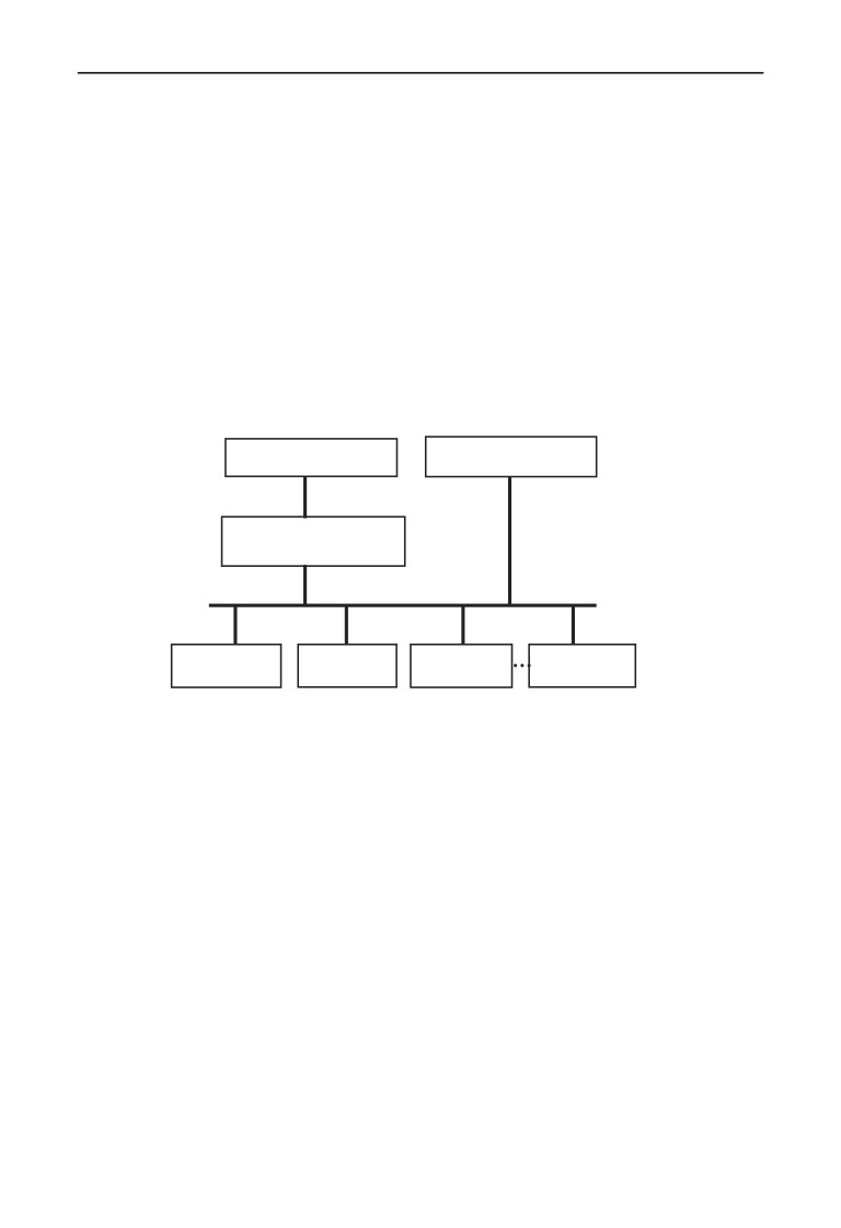
A.2 Communication net buildup mode
mainframe is PC
or
mainframe is PLC
RS232
232-485 conversion
module
RS485
EN600
EN600
EN500
EN500
Fig.A-1 net buildup graph
A.3 Communication mode
At present, EN500/EN600 inverter can be used only as Slave device in RS485 net.
Can realize communication between inverters through PC, PLC or HMI if it’s
needed. Specific communication mode is as mentioned below:
(1) PC or PLC as mainframe,inverter as Slave device, point-to-point
communication between mainframe and Slave device.
(2) Slave device don’t response when mainframe send out command by broadcast
address.
(3) User can set local address, baud rate and data format of the inverter through
Slave device keypad or serial communication mode.
(4) EN500/EN600 provides the RS485 interface.
(5) Default mode: Asynchronous serial,semiduplex transport mode. There are
RTU and ASII two mode . Default format and transport rate: 8-N-1, 9600bps.
225
Appendix A Modbus communication protocol
A.4 Transmission mode
Asynchronous serial, semiduplex transport mode. Default format and transport
rate: 8-N-1, 9600bps. The detail setting parameter, please refer to the F05 group
function mode.
(Remark: the parameter is valid under the Modbus communication, the other
parameter comply with the original service manual)
F05.00
Protocol
0:Modbus protocol
1
0
×
selection
1:Reserved
2:Profibus protocol(expansion is valid)
3:CanLink protocol(expansion is valid)
4:CANopen protocol(expansion is valid)
5:free protocol 1(revision all the parameter of
EN500 is valid)
6: free protocol 2(only revising part parameter
of EN500 is valid)
Remark: expansion card is needed when select
2,3,4 communication
F05.01
Baud rate
The unit digital: free protocol and Modbus
1
005
×
setting
Baud rate selection
0:300BPS
1:600BPS
2:1200BPS
3:2400BPS
4:4800BPS
5:9600BPS
6:19200BPS
7:38400BPS
8:57600BPS
F05.02
Data format
LED the unit digital: free protocol and Modbus
00
×
protocol Data format
0:1-8-1 format,no checkout,RTU
1:1-8-1 format,Odd Parity,RTU
2:1-8-1 format,Even Parity,RTU
3:1-7-1 format,no checkout,ASCII
4:1-7-1 format,Odd Parity,ASCII
5:1-7-1 format,Even Parity,ASCII
F05.03
Local address
0~247,00 is broadcast address
1
1
×
A.5 Data communication structure
A.5.1 Data frame format
Using RTU mode, messages are sent at least 3.5 character time interval pause.
The first transmitted field is device address, the character you can transfer is
hexadecimal 0x00 ~ 0xFF. Network equipment Continuously monitor the bus,
including pauses. When the address field is received, all equipment determine
whether it is sent to their own. when the last character of the packet transfer is
complete, at least a 3.5 character times pause mean the end of the message. A new
226
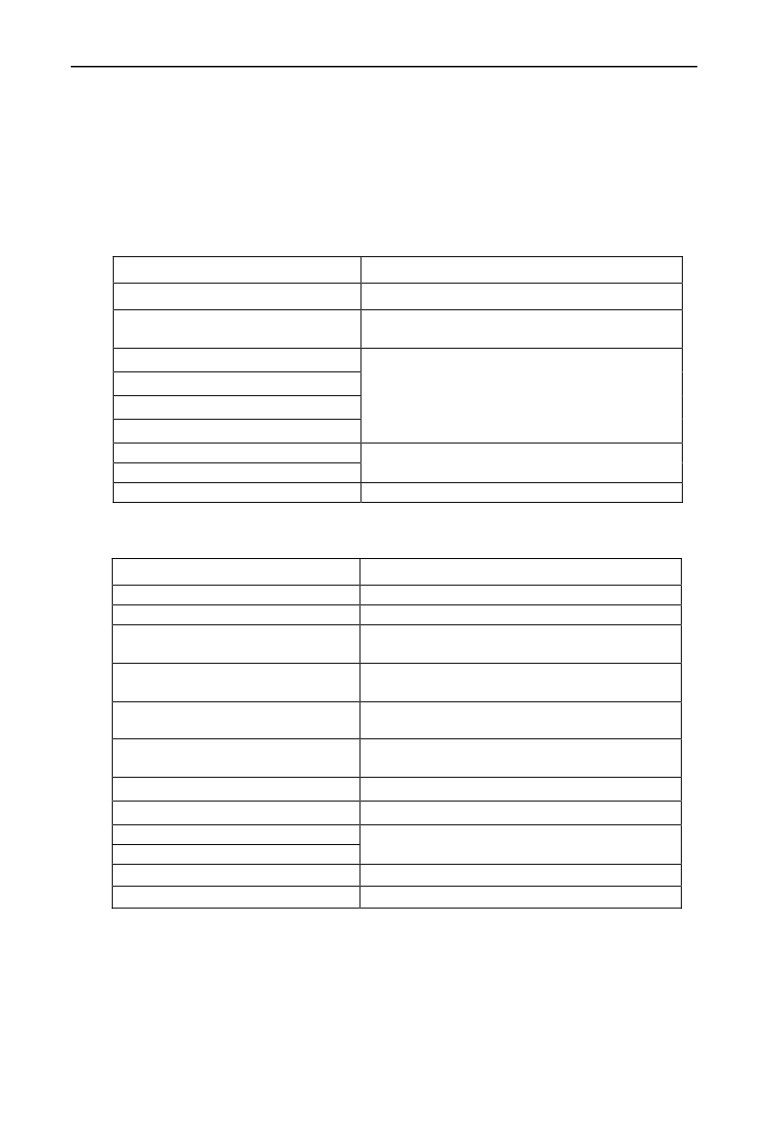
Appendix A Modbus communication protocol
message can begin after this pause.
The entire message frame must be transmitted as a continuous flow. If a new
message start transmitting in less than 3.5 character times after a message and
then receiving device will consider it a continuation of the previous message. This
will cause an error, because in the final CRC field value can not be right.
RTU frame format as the table below:
Frame Header
3.5 characters time pause
Slave address
Slave address:0~247
03H:read slave parameter
Communication command code
06H:write slave parameter
Data content DATA
The contents of packet:
Parameter address(16bit);
Data content DATA
Number of parameter or bytes of parameter
……
value;
……
Parameter value(16bit)
CRC check value low byte
16bit Unsigned check value
CRC check value high byte
Closing Flag
3.5 characters time pause
Regarding generation method of CRC check value, please refer to Section A.9.
ASCII frame format as the table below:
Frame Header
‘:’(0x3A)
Slave address Hi
Slave address: Combined by 2 ASCII code
Slave address Lo
8 bit slave address 0~247
Command code: 8 bit command code
Command code Hi
combined by 2 ASCII code
03H:read slave parameter
Command code Lo
06H:write slave parameter
Data content DATA
The contents of data packet:
N pieces of 8bit data content combined by 2*N
Data content DATA
pieces of ASCII code
……
……
LRC CHK Hi
LRC check value includes 2 pieces of ASCII
LRC CHK Lo
code
Closing Flag Hi
Closing Flag Hi = CR(0x0D)
Closing Flag Lo
Closing Flag Lo = LF(0x0A)
A.5.2 Host read slave parameter
Command code 03H. Host can read one or more parameter( up to ten) by
initiating a communication transaction .
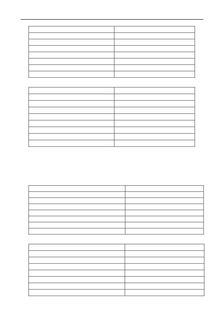
E.g., read 2 contiguous inverter parameter values from the address 0000H of
inverter whose address is 01, the contents of host command :
227
Appendix A Modbus communication protocol
ADR
01H
CMD
03H
Parameters initial address high byte
00H
Parameters initial address low byte
00H
Number of parameter high byte
00H
Number of parameter low byte
02H
CRC check value low byte
C4
CRC check value high byte
OB
The contents of slave reply:
ADR
01H
CMD
03H
Parameter value bytes
04H
Address 0000H content high byte
00H
Address 0000H content low byte
00H
Address 0001H content high byte
00H
Address 0001H content low byte
03H
CRC check value low byte
BA
CRC check value high byte
F2
A.5.3 Host write slave parameter
Command code 06H. Host can write an parameter by initiating a
communication transaction .
E.g.,The decimal system 5000 (1388H) written to the inverter 0101H address
whose slave address is 02,host command including:
ADR
02H
CMD
06H
Parameter address high byte
01H
Parameter address low byte
01H
Parameter value high byte
13H
Parameter value low byte
88H
CRC check value low byte
D4
CRC check value high byte
93
The contents of slave reply:
ADR
02H
CMD
06H
Parameter address high byte
01H
Parameter address low byte
01H
Address 0101H content high byte
13H
Address 0101H content low byte
88H
CRC check value low byte
D4
CRC check value high byte
93
228
Appendix A Modbus communication protocol
A. 6 Data communication address allocation
A.6.1 Function code F00-F26 group communication address
Inverter function parameter’s MODBUS communication address addressing
process follows PPnn way: PP means high byte of the address, corresponding to
function parameter’s group number; nn means low byte of the address,
corresponding to function code parameter’s group internal code. For example:
F3.21 function code’s communication address is 0315H, 03H is the hex form of
group number 3, 15H is the hex form of group internal code 21.
F00.00~F26.17 communication address is 0000H~1A11H, F26 group fault record
parameter start address is 1A00H.
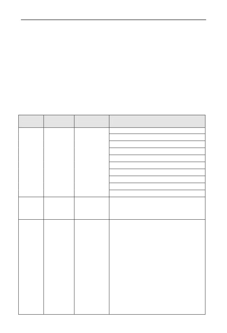
A.6.2 control command and status word communication address
Variable
Communicat
Reading-writin
Command data or response value meaning
Name
ion address
g attribute
1: reserved
2: reserved
3: forward JOG run
4: reversal JOG run
Run
Reading and
5: run
command
1 E 00H
writing
6: stop
word
7: forward run
8: reversal run
9: fault reset
10: reserved
Serial
port
Reading and
1E 01H
0~10000(0~max)
value
writing
setting
BIT0: bus voltage set
BIT1: the ordinary run command effectively
BIT2: JOG command effectively
BIT3: Running
BIT4: the current running direction is reverse
BIT5: the operating instructions is reverse
direction
BIT6: deceleration braking
Inverter
1E 02H
Reading only
BIT7: acceleration
status
BIT8: deceleration
BIT9: alarm
BIT10: fault
BIT11: current limit
BIT12: fault self recovery
BIT13: self tuning
BIT14: Free stop State
BIT15: speed tracking start
229
Appendix A Modbus communication protocol
Alarm
0: no alarm
1E 03H
Reading only
code
1 ~ 50: the current alarm code
Modbus communication address 1E01(frequency given)can be
torque setting and pressure setting address
Note
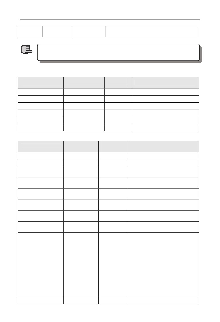
A.6.3 Monitor parameter communication address
Communication
read-write
Variable name
Command data or response value
address
attribute
C-00
1C00H
Reading
Monitoring parameters 1
C-01
1C01H
Reading
Monitoring parameters 2
C-02
1C02H
Reading
Monitoring parameters 3
C-03
1C03H
Reading
Monitoring parameters 4
C-04
1C04H
Reading
Monitoring parameters 5
C-05
1C05H
Reading
Monitoring parameters 6
A.6.4 Inside hidden parameters
Communicatio
read-write
means of command data or response
Variable name
n address
attribute
value
Reserved
1D00H
/
Reserved
1D01H
/
Communication AO1
1D02H
read-write
Range: 0~4000
given value
Communication AO2
1D03H
read-write
Range: 0~4000
given value
Communication
1D04H
read-write
Range: 0~4000
EAO1 given value
Communication
1D05H
read-write
Range: 0~4000
EAO2 given value
Communication
1D06H
read-write
Range: 0~4000
DO given value
Communication
1D07H
read-write
Range: 0~4000
EDO given value
BIT0:Y1
BIT1:Y2
BIT2:Y3
BIT3: Y4
The communication
BIT4: RLY
output terminal given
1D08H
read-write
BIT5: EY1
value
BIT6: EY2
BIT7: EY3
BIT8: EY4
BIT9: ERLY1
BIT10: ERLY2
Communication
1D09H
read-write
BIT0:CX1
230
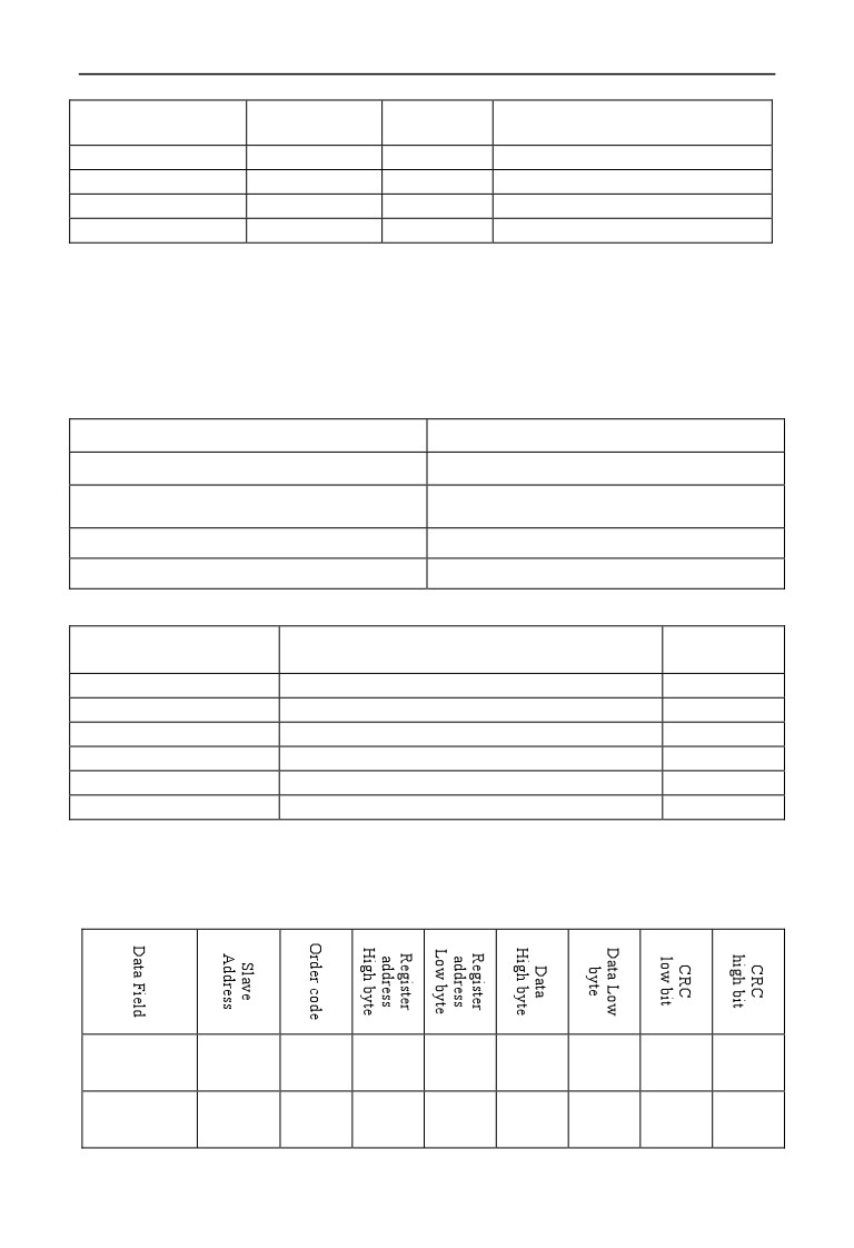
Appendix A Modbus communication protocol
virtual input terminal
…
given value
BIT7: CX8
Reserved
1D0AH
/
Reserved
1D0BH
/
Reserved
1D0CH
/
Reserved
1D0DH
/
A.7 Communication error processing
Inverter receiving data packet detection error, it finds reading&writing parameter
address or parameter value invalid, so reply to the host with communication error
response packet. Communication error response packet (host command code
+80H) as command code, with 1 byte error code.
Format for communication error response packet as follows:
ADR
01H
CMD
83H/86H
01H~06H (for details, please check below
Communication error code
table)
Low byte of CRC checksum
Obtain by calculating
High byte of CRC checksum
Obtain by calculating
Meaning for each communication error code value as follows:
Communication error
Communication error type
Priority
code value
0x01
CRC checksum error
1
0x02
Command code illegal
2
0x03
Register address visited illegal
3
0x04
Value to register illegal
4
0x05
Not allow to modify parameters
5
0x06
Register number read illegal
6
A.8 Data frames examples
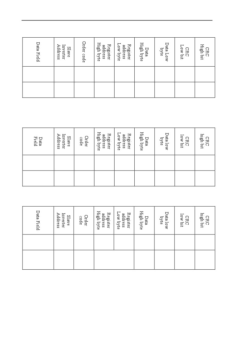
A.8.1 RTU Mode
1. Start #1 inverter running
host
command
01
06
1E
00
00
05
4F
E1
frames
Slave
respond
01
06
1E
00
00
05
4F
E1
frames
231
Appendix A Modbus communication protocol
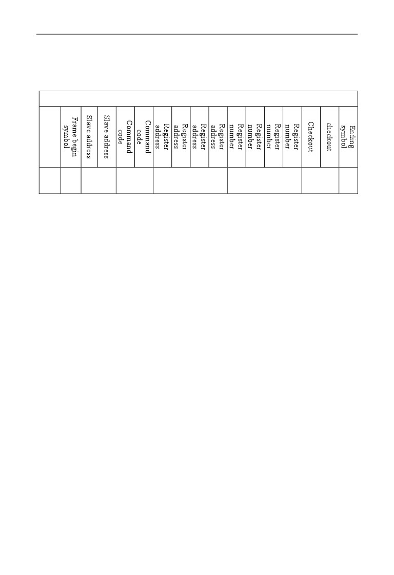
2. Stop #1 inverter running
host
command
01
06
1E
00
00
06
0F
E0
frames
Slave
respond
01
06
1E
00
00
06
0F
E0
frames
3. Set #1 inverter given value to 25Hz (the upper limitation frequency is
50Hz)
host
command
01
06
1E
01
13
88
D3
74
frames
Slave
respond
01
06
1E
01
13
88
D3
74
frames
4. Read #1 inverter running state
host
command
01
03
1E
02
00
01
23
E2
frames
Slave
(Respond value
respond
01
03
byte quantity)
00
01
79
84
frames
02
232
Appendix A Modbus communication protocol
A.8.2 ACSII Mode
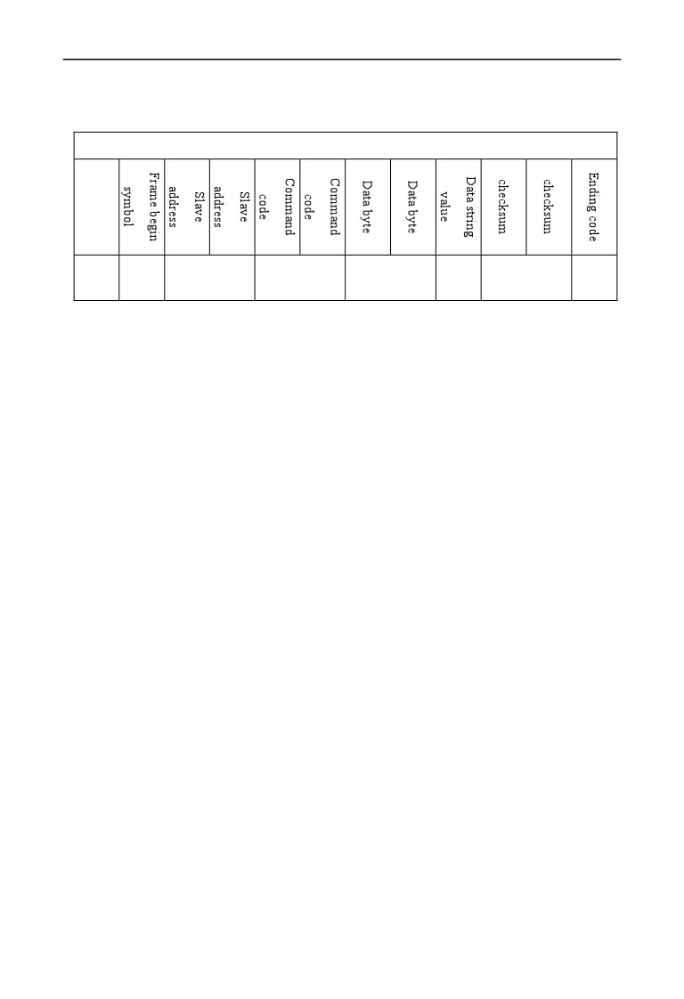
Host read Slave,command code: 03
The host frame
The host frame format
Send
1
2
2
4
4
2
2
byte
Remark:
¾ Begin symbol:
The lower computer judge the frame header of ASCII based on this.
It is:’:’
¾ Slave address:
Single inverter ID code,range:0~247.
Thereinto, 0 is broadcast address. Broadcast address can control all
the lined Slave simultaneously,and the Slave will not send back
any Data to the host. That means the Slave only accept and do not
send.
Modbus protocol without host address.
¾ Command code:
Reading the command of parameter or data from inverter ,the
value is:’0’’3’.
¾ Register address:
The internal memory address of inverter function parameter is of 4
byte, which is ASCII mode transformed from Hexadecimal.
Corresponding relation between specific parameters and
memory address can be seen in the later table.
¾ Register number:
The number of parameters read by a frame, it is 4 byte. It is ASCII
mode transformed from Hexadecimal.
¾ Checksum:
From “slave address” to the character before checksum, the LRC
checksum of the character string. Function terminal can be seen on
the end of the text.
233
Appendix A Modbus communication protocol
¾ Ending code: enter,line break. is:0x0D,0x0A
Response frame
Response frame format
Send
1
2
2
2
N*2
2
2
byte
remark:
¾
Begin code:
The lower computer judge the frame of ASCII frame. This is :’:’
¾
Slave address:
Single inverter ID code,range:0~247.
Thereinto, address 0 is broadcast address. Broadcast address can
control all the lined Slave simultaneously,and the Slave will not
send back any Data to the host. That means the Slave only accept
and do not send.
Modbus protocol is without host address.
¾
Command code:
The command of reading parameter or data from inverter, the value
is:’0’’3’.
¾
Data byte:
The number of parameters read by a frame. It is 4 byte, which is
ASCII mode transformed from hexadecimal.
¾
Data string value:
The detail return Data,the length of Data string is the register
address
“Data byte”, which is ASCII mode transformed from
hexadecimal. Range: 4~40 byte
¾
Checksum:
From “slave address” to the character before checksum, the LRC
checksum of the character string.
The function terminal can be seen in the later text.
¾ Ending symbol: enter, line break. Is 0x0D,0x0A
The followings are the example of command frame and return frame,
all the Data are ASCII character.
234