ENC EN500 / EN600 series inverter (ver. 2.0). Service manual - page 7
Appendix A Modbus communication protocol
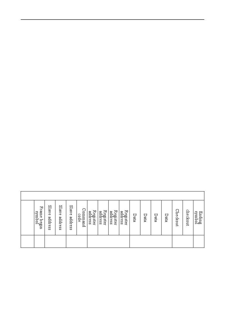
¾ Inquiry frame:
: 0 1 0 3 0 0 0 1 0 0 0 1 F A \n\r
(The detail introduction of every byte)
“:”: beginning symbol
0 1: Slave address
0 3:read the command
0 0 0 1:storage address of reading parameter
0 0 0 1:the number of reading the parameter
F A:{ 0 1 0 3 0 0 0 1 0 0 0 1} for LRC checksum.
0xFA
=
0x100 - (0x01 + 0x03 + 0x00 + 0x01 + 0x00 + 0x01)
¾ Response frame:
: 0 1 0 3 0 2 0 0 3 3 C 7 \n\r
(The detail introduction of every byte)
“:”: beginning symbol
0 1: Slave address
0 3:read the command
0 2:The byte length of return parameter Data.
0 0 3 3:return parameter,current storage value
C 7:{ 0 1 0 3 0 2 0 0 3 3} for LRC checksum.
0xC7 = 0x100 - (0x01 + 0x03 + 0x02 + 0x00 + 0x33)
The main frame writes slave address single register, command code: 06
The host frame
The host frame format
Send
1
2
2
4
4
2
2
byte
Remark:
¾ Slave address:
Single inverter ID code,range:0~247.
Thereinto, address 00 is broadcast address.
¾ Command code:
Read parameter from inverter or command of Data, the value is:06
¾ Register address:
The storage address of inverter function parameter, is double byte.
235
Appendix A Modbus communication protocol
The high byte is in the front and the low byte is in the back.
The detail relation between parameter and storage address can be
seen in the later excel.
¾ Data:
The new value of revised parameter.
¾ Checksum:
From “slave address” to the character before checksum, the LRC
checksum of the character string.
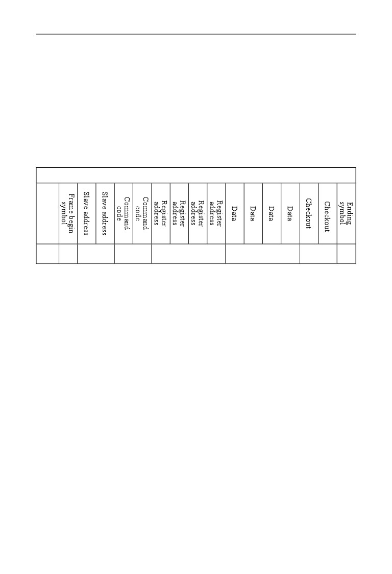
Response frame
Response frame format
Send
1
2
21
4
4
2
2
byte
Remark:
¾ Slave address:
Single inverter ID code,range:0~247.
Thereinto, address 00 is broadcast address.
¾ Command code:
Read parameter from inverter or command of Data, the value is:06
¾ Register address:
The storage address of inverter function parameter, is double byte.
The high byte is in the front and the low byte is in the back.
The detail relation between parameter and storage address can be
seen in the later excel.
¾ Data:
The new value of revised parameter.
¾ Checksum:
From “slave address” to the character before checksum, the LRC
checksum of the character string.
The followings are the example of command frame and return frame, all the
Data are ASCII character.
¾ Inquiry frame:
: 0 1 0 6 0 1 0 1 1 3 8 8 5 C \n\r
236
Appendix A Modbus communication protocol
(The detail introduction of every byte)
“:”: beginning symbol
0 1: Slave address
0 6:write command
0 1 0 1:storage address of writing parameter
1 3 8 8:the value of writing parameter
5 C:{ 0 1 0 6 0 1 0 1 1 3 8 8} for LRC checksum.
0x5C
=
0x100 - (0x01 + 0x06 + 0x01 + 0x01 + 0x13 + 0x88)
¾ Response frame:
: 0 1 0 6 0 1 0 1 1 3 8 8 5 C \n\r
(Detail introduction of every byte)
“:”: beginning symbol
0 1: Slave address
0 6:write command
0 1 0 1:storage address of writing parameter
1 3 8 8:the value of writing parameter
5 C:{ 0 1 0 6 0 1 0 1 1 3 8 8} for LRC checksum.
0x5C
=
0x100 - (0x01 + 0x06 + 0x01 + 0x01 + 0x13 + 0x88)
1. ASCII frame realizes transform by that 8Bit hexadecimal is
divided as different 2 character of 4, and then grouped ashexadecimal
of one 8Bit when reaching the destination.
2. Frame header, add“:”, frame footer adds“\n\r” the enter line
break character.
3. The valid character in the protocol is: :, 0,1,2,3,4,5,6,7,8,9,A,B,C,
D,E,F and hexadecimal 0DH, lower case ASCII letter a, b, c, d, e, f is
Note
invalid
4. The subject data volume is the 2 times as RTU, checksum adopt
LRC check.
5.For the other information, please refer to the official standard
protocol when need.
237
Appendix A Modbus communication protocol
A.9 CRC checkout mode
CRC checkout value calculating function written by C language is as follows:
unsigned int cal_crc_value (unsigned char *pval, unsigned char len)
{
unsigned int crc_value=0xFFFF;
unsigned int i;
while(len--)
{
crc_value ^= *pval++;
for(i=0; i<8; i++)
{
if(crc_value & 0x0001)
{
crc_value >>= 1;
crc_value ^= 0xA001;
}
else
{
crc_value >>= 1;
}
}
}
return(crc_value);
}
238
Appendix B Free-port communication protocol
Appendix B Free-port communication protocol
B. 1 Summarization
We provide the customer with general RS485/RS232 communication interface in
our EN500/EN600 series frequency inverter. For the users, through the
communication interface upper device (such as PC, PLC controller etc.) can
perform centralized monitor to the inverter (such as setting inverter parameter,
controlling run of inverter, reading work state of the inverter) and also
long-distance control keypad can be connected to realize diverse operating
requirement of the user.
This communication protocol is interface criterion file designed for realizing
above-mentioned function, please read it earnestly and program according to it so
that realize long-distance and network control to the inverter.
B. 2 Protocol content aord description
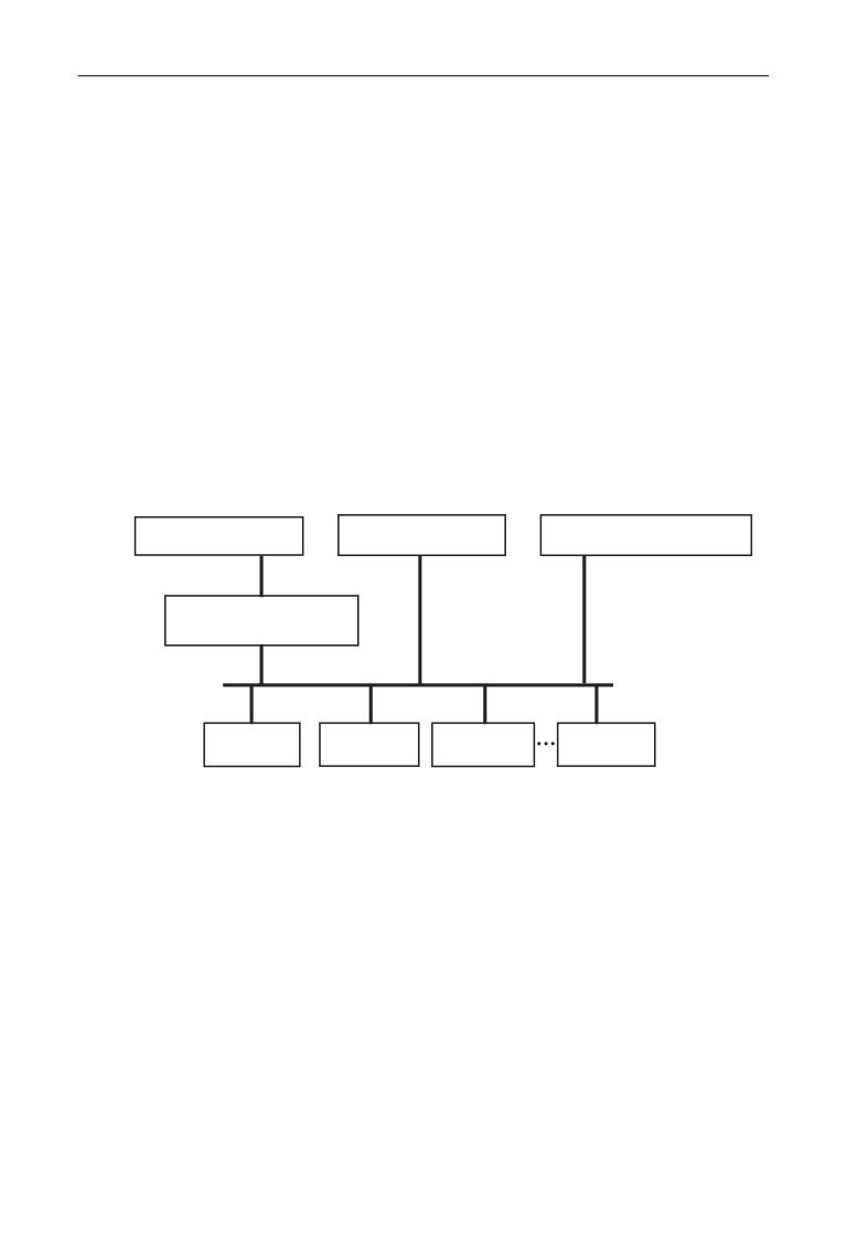
B.2.1 Communication net buildup mode
Mainframe is PC
Mainframe is PC
EN500/EN600 mainframe
or
or
RS232
232-485
conversion module
RS485
EN600
EN600
EN500
EN500
Fig.B-1 net buildup graph
B.2.2 Communication mode
At present, EN500/EN600 inverter can be used as not only auxiliary device but
also mainframe device in RS485, if the inverter is used as auxiliary device,
master device can be completed by PC, PLC or human interface, and if used as
mainframe device, the main- auxiliary control of the inverter can be complement
by it, Specific communication mode is as mentioned below:
(1) PC or PLC as mainframe, inverter as auxiliary device, point-to-point
communication between mainframe and auxiliary device.
(2) Auxiliary device don’t response when mainframe send out command by
broadcast address.
(3) User can set local address, baud rate and data format of the inverter through
auxiliary device keypad.
239

Appendix B Free-port communication protocol
(4) Auxiliary device report current failure information to mainframe in the last
response frame.
(5) EN500/EN600 provides RS485 interface.
B.2.3 Transport mode
Asynchronous serial, semiduplex transport mode. Default format and transport
rate: 8-N-1, 9600bps.For specific parameter setting please see description for F05
group function code.
(Remark: The definition for this parameter is only effective under free -port
communication mode, and definition for other parameters are the same
as
original)
F05.00
Protocol
0:Modbus protocol
1
0
×
selection
1:reserved
2:Profibus protocol(extension effective)
3:CanLink protocol(extension effective)
4:CANopen protocol(extension effective)
5:freedom protocol 1(can modify all function
parameters of EN500/EN600)
6:freedom protocol 2 (can only modify part of
function parameter of EN500/EN600)
Remark: expansion card is needed if select protocol
2,
3,
4
F05.01
Baud rate
LED first bit: freedom protocol and Modbus baud
1
005
×
configuration
rate selection
0:300BPS
1:600BPS
2:1200BPS
3:2400BPS
4:4800BPS
5:9600BPS
6:19200BPS
7:38400BPS
8:57600BPS
F05.02
00
×
Data format
LED first bit: freedom protocol and Modbus protocol
data format
0:1-8-1 format, no checkout, RTU
1:1-8-1 format, even checkout, RTU
2:1-8-1 format, odd checkout, RTU
3:1-7-1 format, no checkout, ASCII
4:1-7-1 format, even checkout, ASCII
5:1-7-1 format, odd checkout, ASCII
F05.03
Local address
0~247, 00 is master station address
1
1
×
240
Appendix B Free-port communication protocol
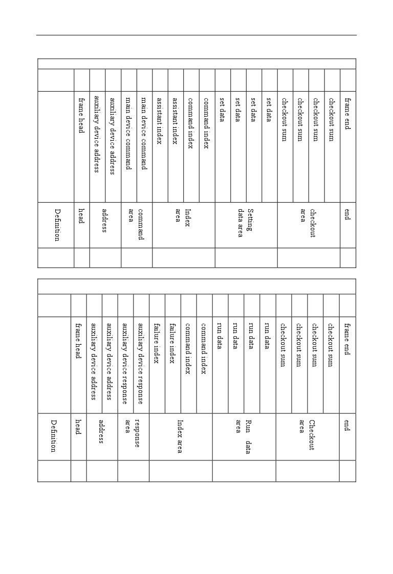
B.2.4 Data command frame format
Main device command frame format
Sending
1
2
3
4
5
6
7
8
9
10
11
12
13
14
15
16
17
18
order
Sending
1
2
2
4
4
4
1
byte
Auxiliary device response frame format
Sending
1
2
3
4
5
6
7
8
9
10
11
12
13
14
15
16
17
18
order
Sending
1
2
2
4
4
4
1
byte
Fig.B-2 command/response frame format
241
Appendix B Free-port communication protocol
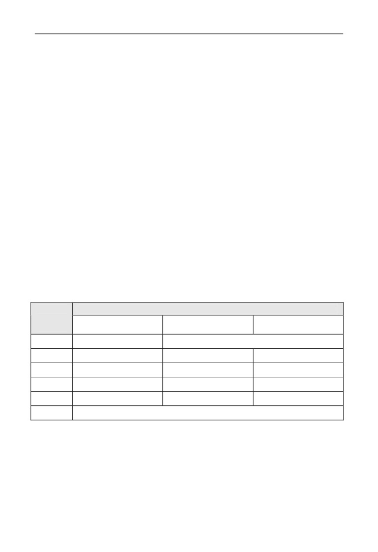
Remark:
(1) “Setting data area” and “run data area” may not be existent in some
command/data frame format, so in protocol command list it’s marked with
“nothing”.
(2) In protocol effective character set is: ~,
1,
2,
3,
4,
5,
6,
7,
8,
9,
A, B, C, D, E, F and hex data 0DH, ASCII lowercase a, b, c, d,
e, f are invalid.
(3) Effective command frame length is 14 or 18 byte.
B.2.5 Explanation and description for format
(1) Frame head
It’s character“~” (namely hex 7E), single byte.
(2) Auxiliary device address
Data meanings: local address of auxiliary device, double byte. ASCII format.
Inverter factory default is 01.
(3) Mainframe command/auxiliary device respond
Data meanings: mainframe send out command and auxiliary device respond to the
command. Double byte, ASCII format.
Response code function classification:
Species 1>: command code=“10”, mainframe ask auxiliary device to report
current preparation state and control situation.
Table B-1 Command code meanings for response frame response area
Response
Meanings
code
Preparation state of
Control from mainframe
To set frequency is
ASCII
auxiliary device
is allowed
allowed
10
Haven’t get ready
No meaning
11
Get ready
Allow
Allow
12
Get ready
Allow
Allow
13
Get ready
Don’t allow
Don’t allow
14
Get ready
Don’t allow
Don’t allow
20
Frame error
Species 2>: command code=“11”~“15”,
5 kinds of function command which
mainframe send to auxiliary device, for detail please see protocol command list.
242

Appendix B Free-port communication protocol
Table B-2 Response code meanings for response frame command index area
Response
code
Meanings of response code
Description
ASCII
Auxiliary device communication and
control is normal ; function code
00
modification is effective;password is
correct.
(1) frame checkout error;
(2)“command area” data overrun;
When this response code is reported,
(3)“index area” data overrun;
data of “command area”,
“index area”
20
(4)frame length error/non ASCII byte
and
“running data area” are not
exist in area except frame head, frame
reported.
end.
(1) control to auxiliary device is
Whether report this response code relate
ineffective;
to current set state of auxiliary device.
(2) ineffective function code parameter
When report data of area”,
“index
30
modification;
area” and “run data area” are reported
(3)“setting/running data” area data
according to protocol
overrun.
requirement.
(4) password error.
(4) Auxiliary index/command index/failure index
Data meanings: include auxiliary index byte and command index byte.
For mainframe, auxiliary index, command index are used for cooperating
mainframe command in realizing specific function.
For auxiliary device, auxiliary index, command index are used for reporting
failure state code, command index are reported without modification
Data type: hex, 4 byte, ASCII format.
Command index occupy 2 low byte, data range: “00”~“FF”.
Auxiliary index occupy 2 high byte, data range: “00”~“FF”.
Auxiliary device failure state occupy “auxiliary index’’ byte, see table B-3.
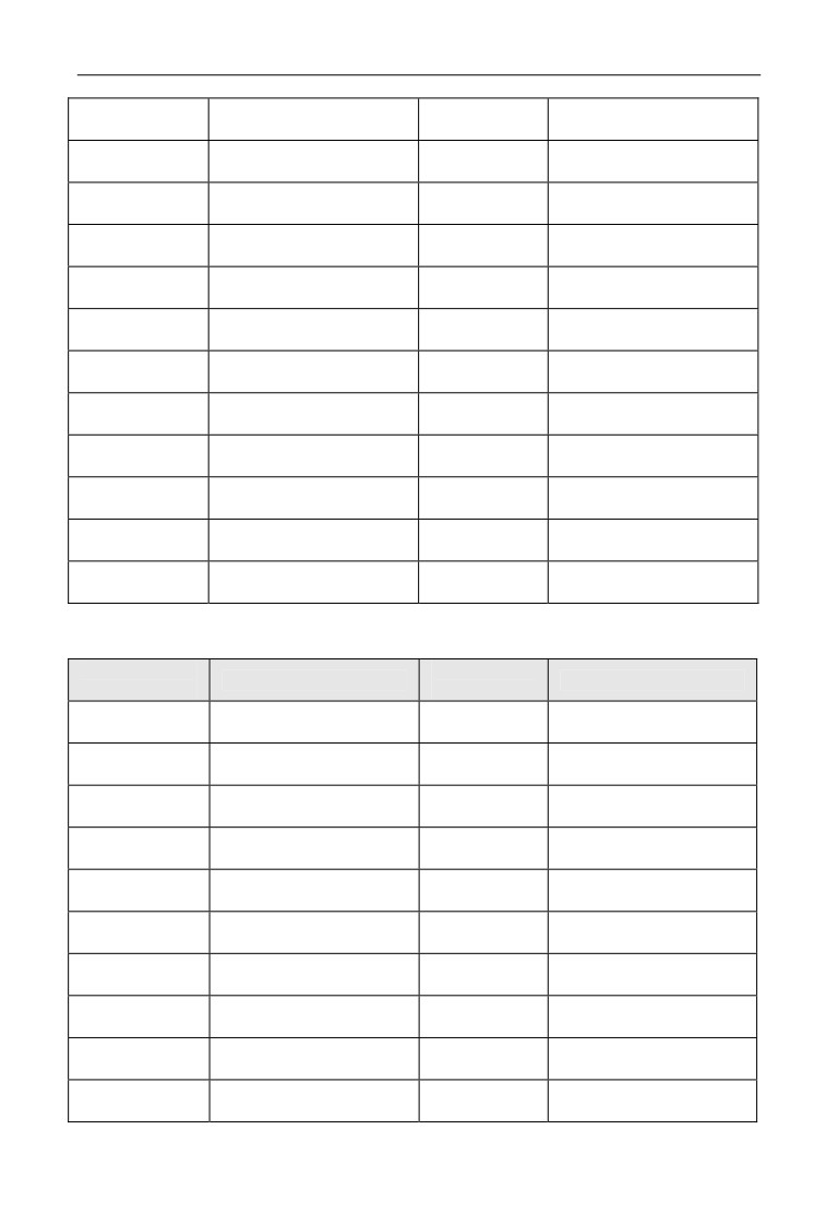
Table B-3 Free-port1 failure type description
Failure
Failure
Description
Description
code(decimal)
code(decimal)
Overcurrent during
Current detecting circuit
1
19
accelerating process
failure
Overcurrent during
External interference
2
20
decelerating process
failure
Overcurrent during
Internal interference
3
21
constant speed process
failure
Overvoltage during
4
22
PID provision loss
accelerating process
Overvoltage during
5
23
PID feedback loss
decelerating process
Overvoltage during
PID error amount
6
24
constant speed process
exception
243
Appendix B Free-port communication protocol
7
Overvoltage while halting
25
Startup terminal protection
Under voltage during
RS485 communication
8
26
running process
failure
Inverter overload
9
27
Reserved
protection
10
Motor overload protection
28
Reserved
Motor underload
11
29
Reserved
protection
E2PROM read and write
12
Input phase missing
30
wrongly
Temperature detection
13
Output phase missing
31
breakage
Inverting module
14
32
Self-tuning failure
protection
Short circuit to earth
15
33
Contactor exception
during running process
Short circuit to earth
16
34
Interior failure 1
during electrifying process
17
Inverter over heating
18
External device failure
Free-port 2 failure type description
Failure
Failure
Description
Description
code(decimal)
code(decimal)
Overcurrent during
Inverting module
1
13
accelerating process
protection
Overcurrent during
2
14
External device failure
decelerating process
Overcurrent during
Current detecting circuit
3
15
constant speed process
failure
Overvoltage during
RS485 communication
4
16
accelerating process
failure
Overvoltage during
5
17
Reserved
decelerating process
Overvoltage during
6
18
Reserved
constant speed process
Control power supply
7
19
Under voltage
overvoltage
8
Inverter overload
20
System interference
9
Motor overload
21
Reserved
10
Inverter over heating
22
Reserved
244
Appendix B Free-port communication protocol
E2PROM read and write
11
Reserved
23
wrongly
12
Reserved
(5) Checkout sum
Data meanings: frame checkout, 4 byte, ASCII.
Calculation method: accumulative sum of ASCII code value of all byte from
“auxiliary device address ”to“ run data”.
(6) Frame end
Hex 0D, single byte.
B.2.6 Protocol command list
Frame 7E and frame end 0D, address, checkout sum, ASCII character format
are omitted in following description.
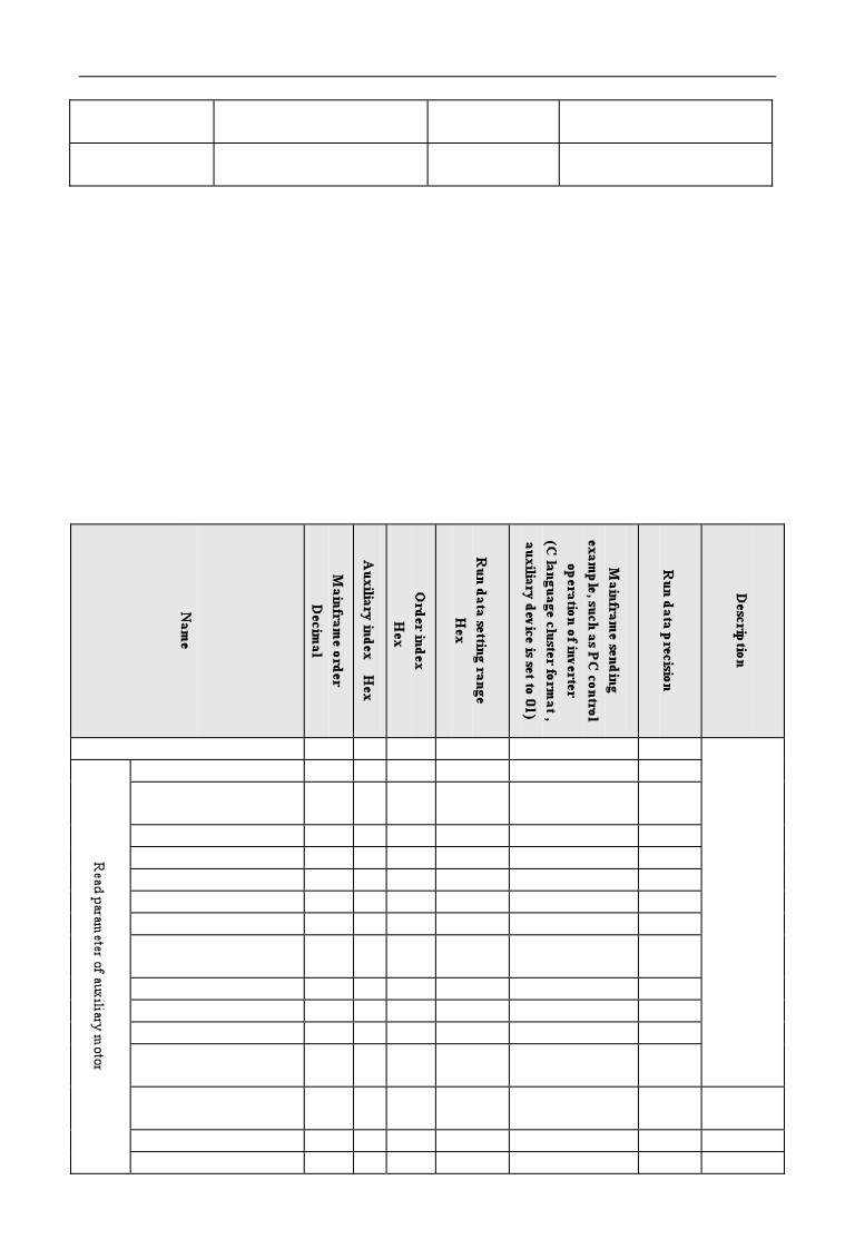
Table B-4 Free-port 1 protocol command table
Look up auxiliary motor state
10
00
00
no
~010A00000192\r
1
Main setting frequency
11
00
00
no
~010B00000193\r
0.01Hz
Auxiliary setting
11
00
01
no
~010B00010194\r
0.01Hz
frequency
Setting frequency
11
00
02
no
~010B00020195\r
0.01Hz
Output frequency
11
00
03
no
~010B00030196\r
0.01Hz
Output current
11
00
04
no
~010B00040197\r
0.1A
Output voltage
11
00
05
no
~010B00050198\r
1V
DC bus-bar voltage
11
00
06
no
~010B00060199\r
0.1V
Load motor revolving
11
00
07
no
~010B0007019A\r
1RPM
speed
Load motor linear speed
11
00
08
no
~010B0008019B\r
no
Inverter temperature
11
00
09
no
~010B0009019C\r
1℃
Runtime
11
00
0A
no
~010B000A01A4\r
0.1min
Current accumulative
11
00
0B
no
~010B000B01A5\r
1h
runtime
Current accumulative
11
00
0C
no
~010B000C01A6\r
1h
power-on time
Inverter state
11
00
0D
no
~010B000D01A7\r
no
Input terminal state
11
00
0E
no
~010B000E01A8\r
no
245

Appendix B Free-port communication protocol
Output terminal state
11
00
0F
no
~010B000F01A9\r
no
Expand output terminal state
11
00
10
no
~010B00100194\r
no
Expanding input terminal state
11
00
11
no
~010B00110195\r
no
Communicational virtual input
11
00
12
no
~010B00120196\r
no
terminal state
Internal virtual input node state
11
00
13
no
~010B00130197\r
no
Analog input AI1
11
00
14
no
~010B00140198\r
no
Analog input AI2
11
00
15
no
~010B00150199\r
no
Expanding analog input
11
00
16
no
~010B0016019A\r
no
EAI1
Expanding analog input
11
00
17
no
~010B0017019B\r
no
EAI2
Analog AO1
11
00
18
no
~010B0018019C\r
no
output
Analog AO2 output
11
00
19
no
~010B0019019D\r
no
Expanding analog EAO1
11
00
1A
no
~010B001A01A5\r
no
output
Expanding analog EAO2
11
00
1B
no
~010B001B01A6\r
no
output
External pulse input
11
00
1C
no
~010B001C01A7\r
1Hz
frequency
Reserved
Process PID provision
11
00
1E
no
~010B001E01A9\r
0.01V
Process PID feedback
11
00
1F
no
~010B001F02AA\r
0.01V
Process PID error
11
00
20
no
~010B00200195\r
0.01V
Process PID output
11
00
21
no
~010B00210196\r
0.01Hz
Simple PLC current
11
00
22
no
~010B00220197\r
no
segments
External multi-section
11
00
23
no
~010B00230198\r
no
speed current segments
Provision pressure for
0.001Mp
11
00
24
no
~010B00240199\r
constant pressure water
a
Feedback pressure for
0.001Mp
11
00
25
no
~010B0025019A\r
constant pressure water
a
Relay state for constant
11
00
26
no
~010B0026019B\r
no
pressure water
Current length
11
00
27
no
~010B0027019C\r
no
Accumulative length
11
00
28
no
~010B0028019D\r
no
Current internal count
11
00
29
no
~010B0029019E\r
no
Current internal time
11
00
2A
no
~010B002A01A6\r
no
Setting channel for run
11
00
2B
no
~010B002B01A7\r
no
command
Main frequency provision
11
00
2C
no
~010B002C01A8\r
no
channel
Auxiliary frequency
11
00
2D
no
~010B002D01A9\r
no
provision channel
Inverter rated current
11
00
2E
no
~010B002E01AA\r
0.1A
Inverter rated voltage
11
00
2F
no
~010B002F01AB\r
1V
Inverter rated power
11
00
30
no
~010B00300196\r
0.1KW
246

Appendix B Free-port communication protocol
Reserved
Reserved
Frequency after
acceleration and
11
00
33
no
~010B00330199\r
0.01Hz
deceleration
Motor rotor frequency
11
00
34
no
~010B0034019A\r
0.01Hz
Current provision torque
11
00
35
no
~010B0035019B\r
0.1%
Current output torque
11
00
36
no
~010B0036019C\r
0.1%
Current torque current
11
00
37
no
~010B0037019D\r
0.1A
Current flux current
11
00
38
no
~010B0038019E\r
0.1A
Auxiliary device run
12
00
00
no
~010C00000194\r
no
command
Set current run frequency
Set freq.
0Hz~high
~010C00010FA002
provision of auxiliary
12
00
01
0.01Hz
=40.00Hz
limit freq
7C\r
device
Auxiliary
Auxiliary device run with
0Hz~high
~010C00020FA002
device run
12
00
02
0.01Hz
run frequency provision
limit freq
7D\r
Set freq.
=40.00Hz
Auxiliary device forward
12
00
03
no
~010C00030197\r
no
run
Auxiliary device reverse
12
00
04
no
~010C00040198\r
no
run
Forward run
Auxiliary device forward
0Hz~ high
~010C00050FA002
boot-strap
run with run frequency
12
00
05
0.01Hz
limit freq
80\r
Set freq.
provision
=40.00Hz
Reverse run
Auxiliary device reverse
0Hz~ high
~010C00060FA002
boot-strap
run with run frequency
12
00
06
0.01Hz
limit freq
81\r
Set freq.
provision
=40.00Hz
Auxiliary device stop
12
00
07
no
~010C0007019B\r
no
Auxiliary device jog run
12
00
08
no
~010C0008019C\r
no
Auxiliary device forward
12
00
09
no
~010C0009019D\r
no
jog run
Auxiliary device reverse
12
00
0A
no
~010C000A01A5\r
no
jog run
Auxiliary device stop run
12
00
0B
no
~010C000B01A6\r
no
Auxiliary device failure
12
00
0C
no
~010C000C01A7\r
no
restoration
Query auxiliary device
15
00
00
no
~010F00000197\r
1
software version
247

Appendix B Free-port communication protocol
Free-Port 2 protocol command table
look up auxiliary motor state
10
00
00
no
~010A00000192\r
1
Auxiliary device run
12
00
00
no
~010C00000194\r
no
command
Set current run freq. of
0Hz~
auxiliary device
12
00
01
high limit
~010C00010FA0027C\r
0.01Hz
freq
Auxiliary device run
0Hz~
with run frequency
12
00
02
high limit
~010C00020FA0027D\r
0.01Hz
provision
freq
Auxiliary device
12
00
03
no
~010C00030197\r
no
forward run
Auxiliary device reverse
12
00
04
no
~010C00040198\r
no
run
Run
Auxiliary device
0Hz~
control
forward run with run
12
00
05
high limit
~010C00050FA00280\r
0.01Hz
and
frequency provision
freq
adjusting
Auxiliary device reverse
0Hz~
function
run with run frequency
12
00
06
high limit
~010C00060FA00281\r
0.01Hz
provision
freq
Auxiliary device stop
12
00
07
no
~010C0007019B\r
no
Auxiliary device jog run
12
00
08
no
~010C0008019C\r
no
Auxiliary device
12
00
09
no
~010C0009019D\r
no
forward jog run
Auxiliary device reverse
12
00
0A
no
~010C000A01A5\r
no
jog run
Auxiliary device stop
12
00
0B
no
~010C000B01A6\r
no
run
Auxiliary device failure
12
00
0C
no
~010C000C01A7\r
no
restoration
Query auxiliary device
15
00
00
no
~010F00000197\r
1
software version
248

Appendix B Free-port communication protocol
Table B-5 read auxiliary device function code parameter
Read auxiliary device function code parameter: all function code parameter except user
Function
password and manufacturer password
definition
except user password and manufacturer password
Frame
Order
Checkout
Frame
Meanings
Address
Order
Run data
head
index
sum
end
Mainframe
See
7EH
ADDR
13
4
BCC
0DH
order
remark
Byte quantity
1
2
2
4
0
4
1
Auxiliary
Function
See
device
7EH
ADDR
06
code
BCC
0DH
remark
respond
parameter
Byte quantity
1
2
2
4
4
4
1
Command index=combination of function code group number and hex code of function
code number. For instance:
If want to read parameter of F0.05 function code, order index=0005;
If want to read parameter of F2.11 function code, order index =020B;
If want to read parameter of F2.15 function code, order index =020F;
If want to read parameter of F2.13 function code, order index =020D;
Corresponding relation between decimal and hex value of function code group No.
Function code
Function code
Decimal
Hex
Decimal
Hex
group No
group No
F00
0
00H
F0E
14
0EH
F01
1
01H
F0F
15
0FH
F02
2
02H
F10
16
10H
F03
3
03H
F11
17
11H
remark
F04
4
04H
F12
18
12H
13H
F05
5
05H
F13
19
F06
6
06H
F14
20
14H
F07
7
07H
F15
21
15H
F08
8
08H
F16
22
16H
F09
9
09H
F17
23
17H
F0A
10
0AH
F18
24
18H
F0B
11
0BH
F19
25
19H
F0C
12
0CH
F1A
26
1AH
F0D
13
0DH
F1B
27
1BH
Virtual data
0~FFFF (namely 0~65535)
Please input correct “user password” before you set user function code parameter.
249

Appendix B Free-port communication protocol
Table B-6 set auxiliary device function code parameter
Function
Set auxiliary device function code parameter: all function code parameter except user password
definition
and manufacturer password
Frame
Order
Checkout
Meanings
Address
Order
Run data
Frame end
head
index
sum
Mainframe
7EH
ADDR
14
See remark
4
BCC
0DH
order
Byte quantity
1
2
2
4
4
4
1
Auxiliary
Function
device
7EH
ADDR
06
See remark
code
BCC
0DH
respond
parameter
Byte quantity
1
2
2
4
4
4
1
Command index=combination of function code group number and hex code of function code
number. For instance:
If want to read parameter of F00.05 function code, order index=0005;
If want to read parameter of F02.11 function code, order index =020B;
If want to read parameter of F02.15 function code, order index =020F;
If want to read parameter of F02.13 function code, order index =020D;
Corresponding relation between decimal and hex value of function code group No.
Function code
Function code
Decimal
Hex
Decimal
Hex
group No
group No
F00
0
00H
F0E
14
0EH
F01
1
01H
F0F
15
0FH
F02
2
02H
F10
16
10H
Remark
F03
3
03H
F11
17
11H
F04
4
04H
F12
18
12H
F05
5
05H
F13
19
13H
F06
6
06H
F14
20
14H
F07
7
07H
F15
21
15H
F08
8
08H
F16
22
16H
F09
9
09H
F17
23
17H
F0A
10
0AH
F18
24
18H
F0B
11
0BH
F19
25
19H
F0C
12
0CH
F1A
26
1AH
F0D
13
0DH
F1B
27
1BH
Virtual data
0~FFFF(namely 0~65535)
250
Appendix C Keyboard
Appendix C Keyboard
C.1 Keyboard selection:
NO.
Type
Details
Remark
1
EN-LED1
Local LED single-display keyboard
Standard
2
EN-LED2
Local LED double-display keyboard
Optional
3
EN-LCD1
Local LCD Keyboard
Optional
4
EN-LCD2
Remote Control LCD Keyboard
Optional
Local LED single-display digital potentiometer
5
EN-LED3-D
Optional
keyboard(with the function of parameter copy)
At present, Our has 4 kinds of optional keyboards for our customers’ selection,
they are EN-LED2, EN-LCD1, EN-LCD2 and EN-LED3-D. Their outer
dimension and installation size are the same as the standard keyboard
EN-LED1 .For more detailed dimension, please refer to “Keyboard Operation and
Outer Size of Keyboard installing box” in Chapter 2.
1. EN-LCD1、EN-LCD2、EN-LED3-D are three kinds of keyboard
that with the function of parameter copy
2. Using the function of parameter copy could through operating
Note
parameter F00.27
C.2 LED double display keyboard
Local LED double display keyboard type: EN-LED2
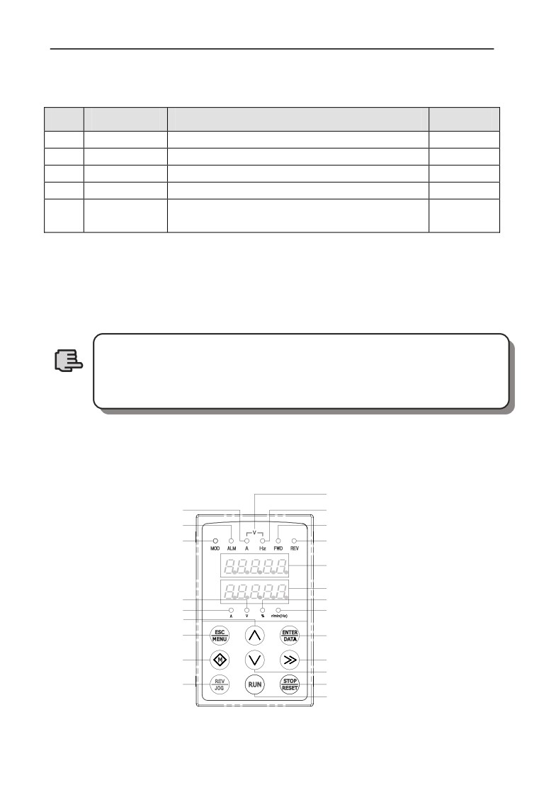
C.2.1 Keyboard Layout
Voltage indicator light(LED1)
Current indicator light(LED1)
Frequency indicator light(LED1)
Failure alarm indicator light
Forward run indicator light
Mode indicator light
Reverse run indicator light
Digital display(LED1)
Digital display(LED2)
Voltage indicator light(LED2)
Parameter percent(%)
Current indicator light(LED2)
Speed(r/min)/Freq(Hz)indicator
Increase key
Exit/Program key
Confirm/Data key
Multiple function key
Shift/Supervision key
Decrease key
Reverse/Jog key
Stop/Reset key
Forward run key
Fig.C-1 EN-LED2 Operating Keyboard Layout
251
Appendix C Keyboard
C.2.2 Description for keyboard functions, LED digital tubes and indicator
lights
Double-display keyboard consists of two 5-digit digital tube screens,9 buttons and
10 indicator lights.
If need more details about function definition of the 9 buttons, LED digital tubes
and specification of the indicator lights, then please refer to “Keyboard Function
Specifications” in Chapter 5.
LED2 digital tube supervision is set by parameter F00.25.
Note
C.3 LCD keyboard
C.3.1 LCD keyboard series:
(1) Local LCD keyboard type: EN-LCD1
(2) Remote control LCD keyboard type: EN-LCD2
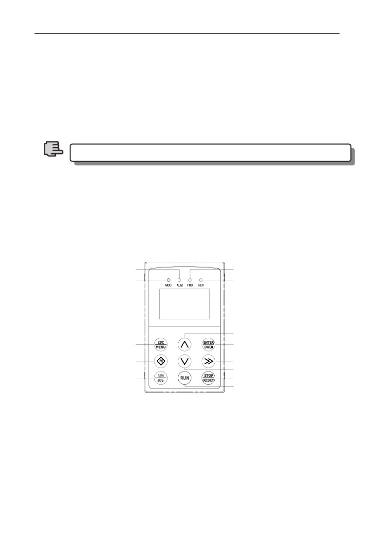
C.3.2 Keyboard Layout
Failure alarm indicator light
Forward run indicator light
Mode indicator light
Reverse run indicator light
LCD screen
Increase key
Exit/Program key
Confirm/Data key
Multiple function key
Shift/Supervision key
Decrease key
Reverse/Jog key
Stop/Reset key
Forward run key
Fig.C-2 Keyboard Layout Sketch (EN-LCD1, EN-LCD2)
C.3.3 Keyboard Function, LCD Display and Spec. of Indicator Lights
LCD keyboard consists of a LCD screen, 9 buttons and 4 indicator lights
LCD screen: To display Function Setting, Running Supervision, Failure
Supervision Code and Parameter.
For more details about function definition of the 9 buttons and specification of the
indicator lights, please refer to “Keyboard Function Specifications” in Chapter 5.
252
Appendix C Keyboard
C.3.4 Operating Spec. of LCD Display Keyboard
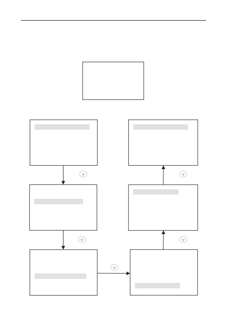
⑴ Initialization status of LCD keyboard when power on
When the keyboard is power on, “Key Board” is displayed in the form of
animation:
Keyboard
Fig.C-3 Initialization Display when Power On
⑵ Operation of switching to firstly menu (Fig. C-4):
F00:System Parameter Group
F00:System Parameter Group
F01:Basic Running Group
F01:Basic Running Group
F02:Start Stop Brake Group
F02: Start Stop Brake Group
F03: V/F Control Group
F03: V/F Control Group
Press
Press
F00:System Parameter Group
F26:Fault Record Group
F01:Basic Running Group
F02: Start Stop Brake Group
F03: V/F Control Group
Press
Press
F00:System Parameter Group
F00:System Parameter Group
F01:Basic Running Group
F01:Basic Running Group
Press
F02:Start Stop Brake Group
F02: Start Stop Brake Group
F03: V/F Control Group
F03: V/F Control Group
Fig.C-4 Power on initialized display
253
Appendix C Keyboard
When set F00.00=2, Senior Menu parameters F00~F27 can be displayed, 28
groups in total. Operation methods are shown as Fig. C-4.
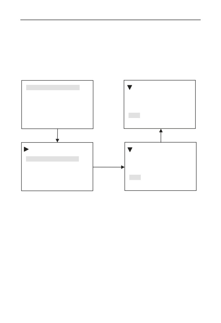
⑶ Display and operation of secondary menu:
When you are in the Firstly Menu, choose a parameter group, then press
“ENTER/DATA” key and you will enter into the Secondary Menu. Take
Parameter F00.00 for example:
F00:System Parameter Group
Parameter Group Display
F01:Basic Running Group
F0000=2
F02:Start Stop Brake Group
2:Senior List Mode
F03: V/F Control Group
Range
0~3
ENTER/DATA
Press increase button
F00:System Parameter Group
Parameter Group Display
00: Parameter Group Display
F0000=0
ENTER/DATA
01:C00 display when operation
0:Basic List Mode
02: C01 display when operation
Range
0~3
Fig.C-5 Example of Secondary Menu Operation
254
Appendix C Keyboard
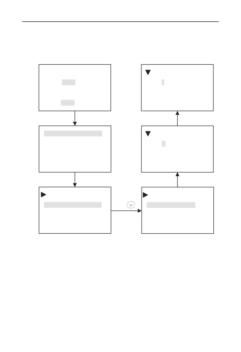
⑷ Function Parameter Operation
Function parameter operation includes the parameter checking, revise and storage
of parameters. Before the operating the inverter, parameters should be set
correctly. Operation methods are shown as Fig. C-6:
Frequency Setting
Motor Control Mode
C00
050.00 Hz
F0024=1
Frequency Setting
1:Speedless Vector Control
050.00 Hz
Range:
0~2
ESC/MENU
Press increase button
F00:System Parameter Group
Motor Control Mode
F01:Basic Running Group
F0024= 0
F02:Start Stop Brake Group
0:V/F Control
F03: V/F Control Group
Range:
0~2
ENTER/DATA
ENTER/DATA
F00:System Parameter Group
F00:System Parameter Group
00: Parameter Group Display
Press
24: Motor Control Mode
01:C00 display when operation
25:Supervision
2 selection
02:C01 display when operation
26:Busbar voltage coefficient
Fig.C-6 Example of function parameter editing
255
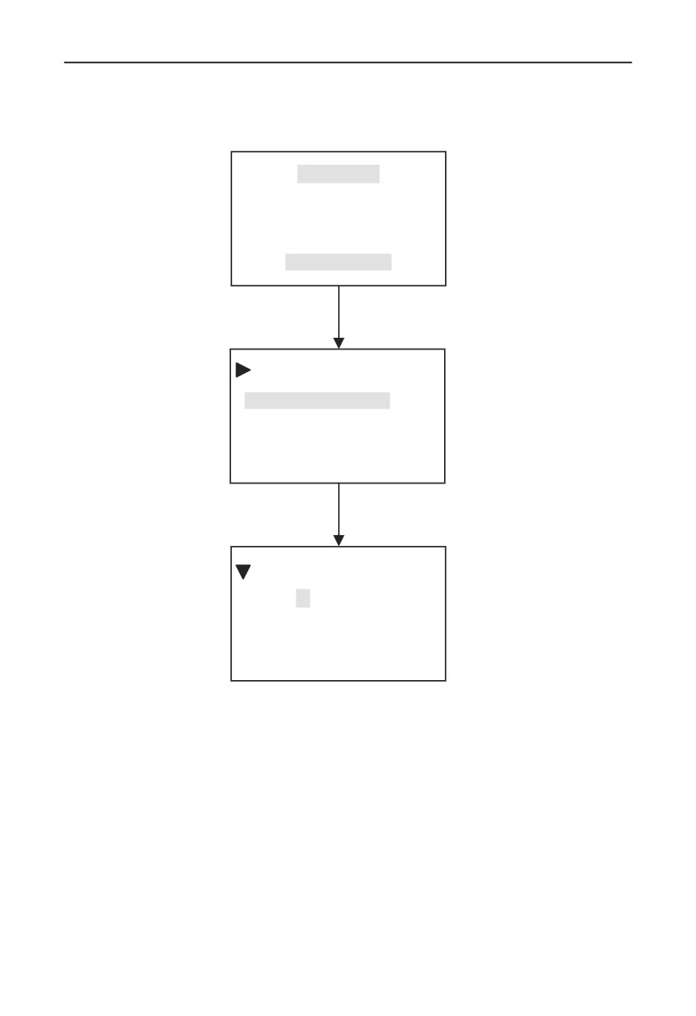
Appendix C Keyboard
⑸ Fault query status
When fault alarm occurs, customers can enter the fault query status:
Fault Alarm!
E13
Output Phase Loss
ESC/MENU
F26:Fault Record Parameter
00:The Last Fault Record
01:The Last Two Fault Record
02: The Last Three Fault Record
ENTER/DATA
The Last Fault Record
F2600=13
13:Output Phase Loss
Range
00~50
Fig.C-7 Fault query status
256
Appendix C Keyboard
C.4 LED single-display digital potentiometer keyboard
The type of local single-display digital potentiometer keyboard:EN-LED3-D。
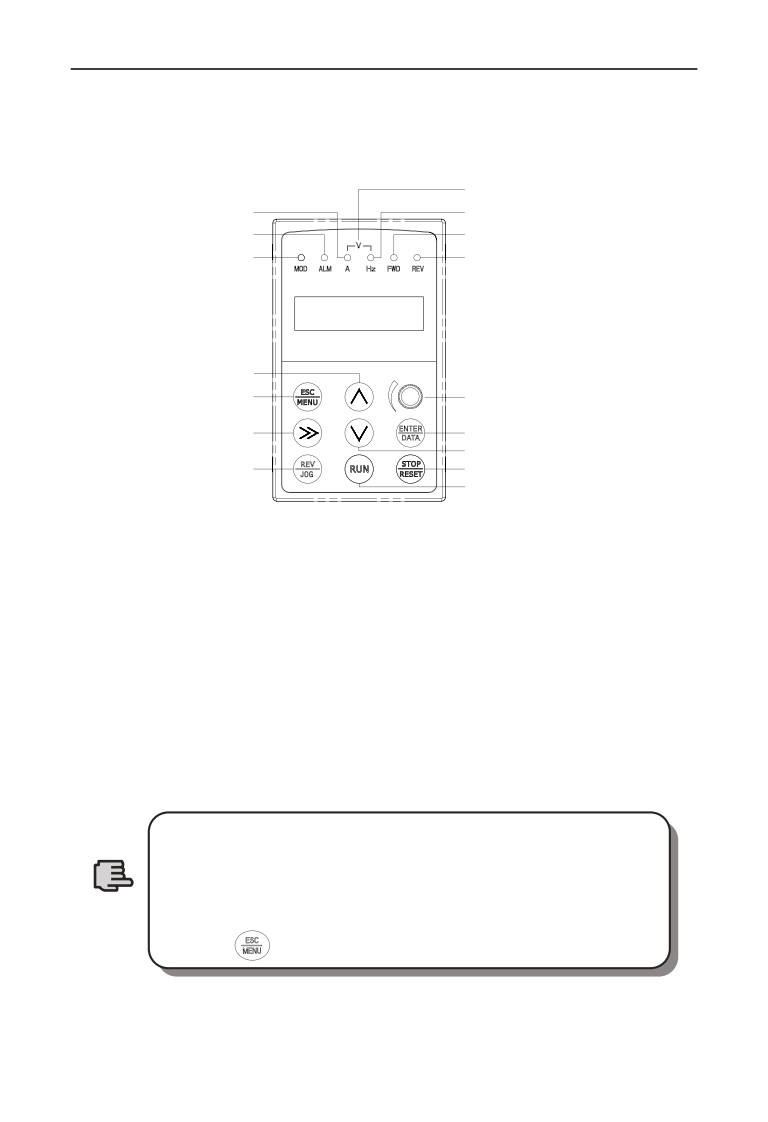
C.4.1 Keyboard Layout
Voltage indicator light
Current indicator light
Frequency indicator light
Failure alarm indicator light
Forward run indicator light
Mode indicator light
Reverse run indicator light
Increase key
Exit/Program key
Digital potentiometer
Shift/Supervision key
Confirm/Data key
Decrease key
Reverse/Jog key
Stop/Reset key
Forward run key
Fig.C-8 EN-LED3-D Operation keyboard layout
C.4.2 Keyboard function、LED Nixie tube and indicator light description
LED single-display digital potentiometer keyboard is composed of a 5-digit nixie
tube display、8 keys and a digital potentiometer.
For the function definition of 8 keys in operation keyboard、LED nixie tub and
indicator light description, please see also the keyboard function description in
chapter 5.
Digital potentiometer function description:it is the same as the function of
increase and decrease key,rotate to the left means decrease,rotate to the right
means increase.
1.EN-LED3-D operation keyboard is different with the
standard configured EN-LED1 in the key site, please pay
attention to the key site when using EN-LED3-D
2.EN-LED3-D keyboard is different with other keyboards in
Note
unlocking way, unlocking way of EN-LED3-Dkeyboard is
pressing
key for more than 2 seconds.
257
Appendix C Keyboard
C.5 Communication Component
The maximum electric distance between keyboard EN-LED1, EN-LED2,
EN-LCD1, EN-LED3-D and local inverter is 2m.
RS485 communication mode is adopted between inverter and remote keyboard
EN-LCD2, only an ordinary cable is needed to connect each other, and their
maximum electric distance can be 1000m. When the communication with each
other is main-auxiliary mode, namely take remote keyboard as main device and
inverter as auxiliary device. The terminals of the connection cable are made by
crystal ends, so it is easy to maintain. Power needs customers’ outer leading,the
voltage range is from 10V to 24V,the demand current is 150mA,1mm2 of PVC
insulate copper wire is suggested to connect.
Following function can be realized by remote keyboard:
(1) Can control run, stop, jog, failure reset, change setting frequency, modify
function parameter and run direction of auxiliary device.
(2) Can identify the type of auxiliary device. Can monitor the running frequency,
setting frequency, output voltage, output current, analog closed loop feedback,
analog closed loop setting and exterior counting value of auxiliary device.
258
Appendix D Communication extension card
Appendix D Communication extension card
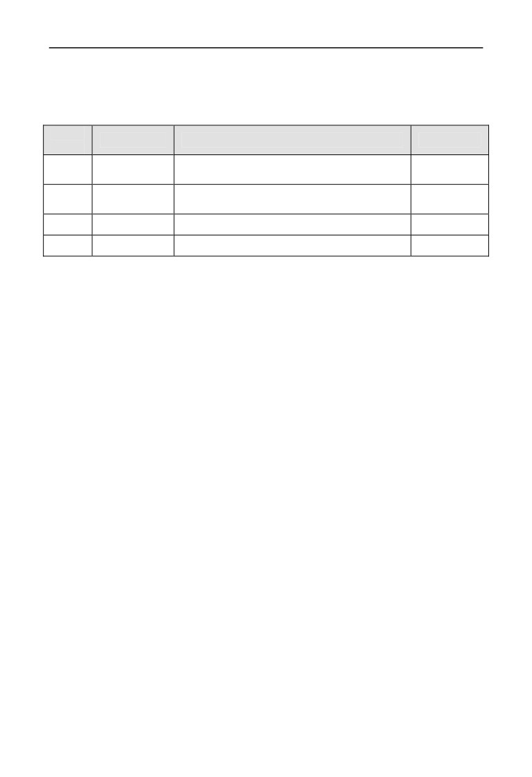
D.1 Communication card selection:
At the present, there are four kinds of communication card can be selected for.
Serial
Type
Description
Remark
No.
PROFIBUS-DP communication card (use
1
EN-PR01
Optional
in 15KW and the below )
PROFIBUS-DP communication card (use
2
EN-PR02
Optional
in 15KW the above)
3
EN-CAN1
CANopen communication card
Optional
4
EN-CAN2
CANlink communication card
Optional
D.2 PROFIBUS-DP communication card
D.2.1 PROFIBUS introduction
(1)PROFIBUS (short for Process Field Bus ),PROFIBUS is an international and
open field bus standard independent with manufacturer. It can be support for
many equipment manufacturers, with good compatibility. It’s widely used in
Manufacturing Automation, automation of process industry, and other buildings,
transportation, electric power automation field.
(2)PROFIBUS can realize exchanging the data between all kinds of element of
automation, all of this equipment can exchange the information though the same
port. But the transmission rate is different .all the automatic equipment can
exchange the information though the same port, but with the different rates, so
PROFIBUS should offer different types for the speed rates selection. it is made up
with PROFIBUS-DP(Distributed peripheral ),
PROFIBUS-PA,PROFIBUS-FMS.
(3)PROFIBUS (RS485), the first layer realize the balanced data transmission,
wire a bus segment one Bus segment is shielded twisted pair cable, both ends of
the segments have a terminating resistor. Transmission mode to half duplex,
asynchronous, synchronous gap-free data exchange basis, the physical layer
supports fibre, the data frame 11, and the transfer rate: 9.6Kbit / sec-12Mbit / sec.
Bus length range from 100 to 1200 meters
(4)Between same-level controller and PC communications
(token passing
procedure), to ensure adequate opportunity to deal with their communication tasks
in a determined time. Complex PLC and PC with a simple division formula I / O
communications, you must quickly and with minimal protocol overhead (master -
slave program)
259
Appendix D Communication extension card
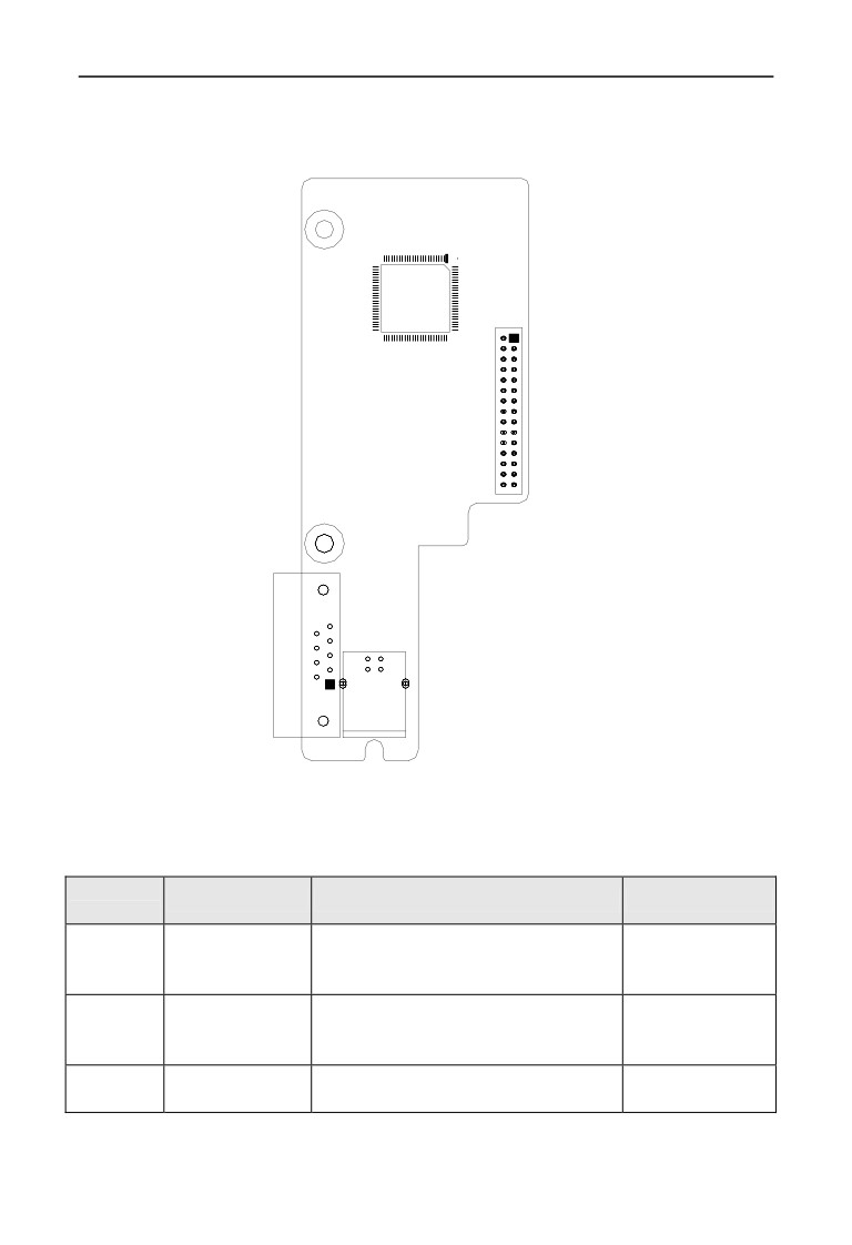
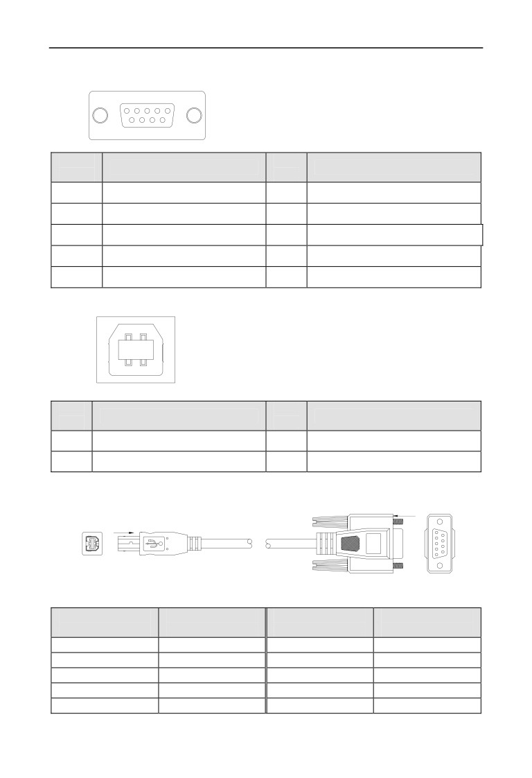
D.2.2 The external form of PROFIBUS-DP and terminal definition
description
JP2
J2
J3
Fig D-1 PROFIBUS-DP outline dimensional drawing
Table D-1 Terminal function description
Terminal
Name
Description
Remark
date
Use it on 15KW
USB form adapter
USB connection factory and distribution to
J2
frequency inverter or
plugs
DB9 adapter cable
below
Use it on 15KW
DB9
communication signal connection
J3
frequency inverter or
communication port
interface,9-pin DB9 female.
the above
Board-level
When you install this plug docking with the
JP2
docking connector
main control board CN2
260
Appendix D Communication extension card
(1)J3 Plug pin definition :
5
1
9
6
PIN
PIN
Definition
Definition
data
data
1
bit bare
6
VCC
2
bit bare
7
bit bare
3
Communication signal A
8
communication signal B
4
bit bare
9
bit bare
5
GND
-
-
(2)J2 Plug pin definition :
2
4
1
3
PIN
PIN
Definition
Definition
data
data
1
Communication signal A
3
GND
2
Communication signal B
4
VCC
(3)J2 switch wiring
Direction B
Right plug
Direction B
A向
Direction A
Left plug
Direction A
1
6
3
4
1
2
5
9
Table D-2 The left end plug and The right end plug PIN data
The left end plug
The right end plug
The left end plug
The right end plug
PIN data
PIN data
PIN data
PIN data
-
1
4
6
-
2
-
7
1
3
2
8
-
4
-
9
3
5
-
-
261
Appendix D Communication extension card
D.3 CANopen communication card
D.3.1 CANopen introduction
CANopen is an architecture in the control area network (Controller Area Network,
CAN) on the high-level communication agreements, including communication
equipment sub-sub-agreements and agreements, often used in embedded systems,
industrial control is a commonly used fieldbus. CANopen implements the network
layer and above the agreement OSI model. CANopen standard includes
addressing scheme, several small communication sub-agreements
D.3.2 Equipment model
Communication agreement on other modules communication processing and
network communication unit needed to start and reset the device has a state
machine control. State machine include: Initialization, Pre-operational,
Operational, Stopped.
D.3.3 Object Dictionary
Object Dictionary (OD: Object Dictionary) is an ordered group of objects; each
object using an index value of 16 is addressed, in order to allow access to the data
structure of a single element, while the definition of an eight sub-indexes.
D.3.4 Communication
(1)Communication objects: Management packets, Service Data Objects (SDO),
process data objects (PDO), the pre-definition packet or special function object
(2)Communication model: master/slave model, client/server model,
producer/consumer model
D.3.5 Agreement
(1) NMT Agreement
(network management, network management): Status
Agreement definition of the state machine change commands (such as starting or
stopping the equipment), to detect remote device bootup and failure scenarios.
(2) Heartbeat Agreement: nodes in the network to monitor and confirm it is
working properly.
(3) SDO agreement: between devices used to transfer large low-priority data,
typically used to configure devices on the CANopen network.
(4) PDO Agreement: 8 bytes or less used to transmit data, no other agreement
preset (which means data has been pre-definition).
262
Appendix D Communication extension card
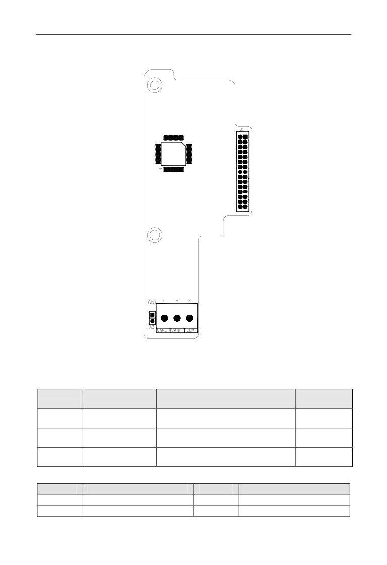
D.3.6 CANopen form and terminal definition description
Fig D-2 CANopen outline dimensional drawing
Table D-3 Terminal function description
Terminal
Name
Description
Remark
number
Communication
By the client device connected to the CAN
CN1
wiring terminal
bus communication
When you install this plug docking with
J1
Signal port
the main control board CN2
Terminal resistor
Connect J2, then terminal resistor connect
J2
access entry
to bus
(1)CN1 pin definition
PIN data
Definition
PIN data
Definition
1
signal CANL
3
COM
2
signal CANH
-
-
263
Appendix D Communication extension card
D.4 CANlink communication card
D.4.1 CANlink introduction
The physical layer CANlink card is CAN bus, only supports CAN2.0B extended
frame. Since the control signal CANlink card connected directly to the main board,
compared with CANOPEN card, with high transmission efficiency, real-time,
stability and other characteristics, the maximum transfer rate of 1Mbps. CAN bus
data transmission using a differential signal, with strong anti-interference,
transmission distance and other characteristics, the communication rate 5Kbps
below, the farthest reach 10Km, at 1Mbps baud rate up to 30m.
CANlink protocol is self-definition protocols, support for modifications and
inverter terminal parameters monitoring.
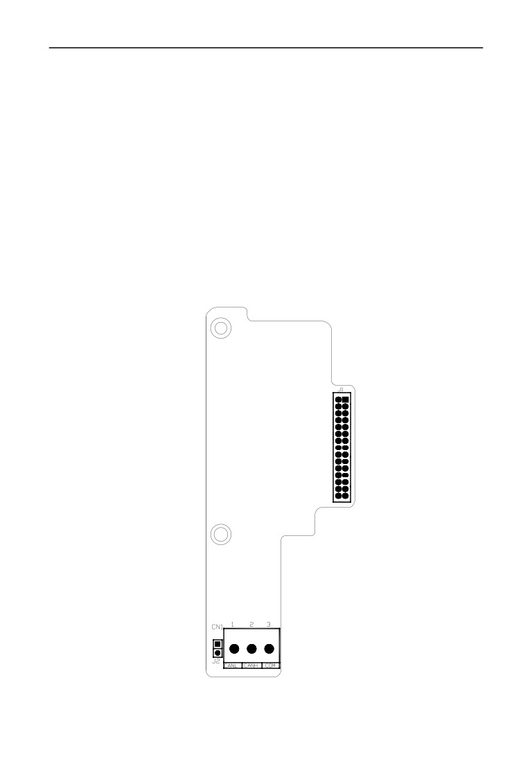
D.4.2 CANlink card figure and terminal definition description
Fig D-3 CANlink Dimensions
264
Appendix D Communication extension card
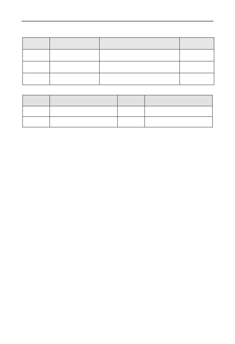
Table D-4 Terminal function description
Terminal
Name
Description
Remark
Number
Communication wiring
By the client device connected to the
CN1
terminal
CAN bus communication
When you install this plug docking with
J1
Signal port
the main control board CN2
Terminal resistor access
Connect J2, then terminal resistor
J2
entry
connect to bus
(1) The definition of CN1 pin.
PIN data
Definition
PIN data
Definition
1
Signal CANL
3
COM
2
Signal CANH
-
-
265
Appendix E Universal encoder expansion card
Appendix E Universal encoder expansion card
E.1 The selection of encoder expansion card:
Universal encoder expansion card (PG card), As an option to use, it is the
necessary option for closed loop vector control inverter.
No.
Model
Description
Remark
Differentiator input PG card, encoder
1
EN-PG01
input signal not isolated (suitable for all
Optional
series machine)
Differentiator input PG card, encoder
input signal through the optocoupler
2
EN-PG02
Optional
isolation, stronger anti-interference ability
(suitable for all series machine)
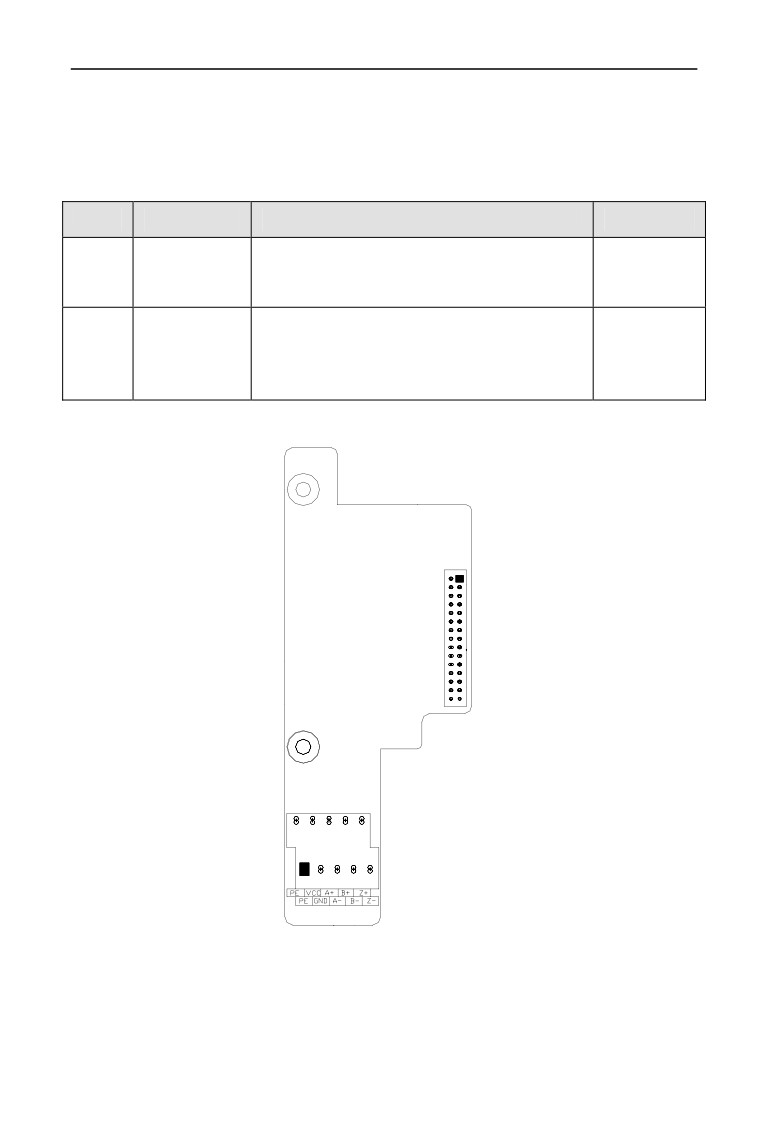
E.2 PG card shape and terminal definitions
CN1
CN2
2
4
6
8
10
1
3
5
7
9
Fig.E-1 EN-PG01, EN-PG02 Outline dimension drawing
266
Appendix E Universal encoder expansion card
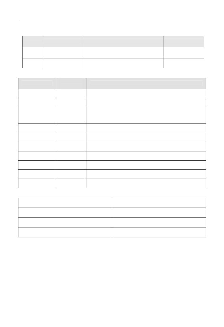
Table E-1 Terminal function description
Terminal
Name
Description
Remark
number
Board and board
When installing the plug and the main
CN1
Butt socket
control board CN2 docking
CN2
The user interface
The encoder uses
(1) CN2 Terminal definitions
Terminal
PIN data
Description
labeling
1
PE
Shielding terminal
2
PE
Shielding terminal
Power supply (GND of EN-PG01 and GND of control panel
3
GND
is connect. GND of EN-PG02 and GND of control panel
isolation)
4
VCC
Provide 5V/300mA current toward outside
5
A-
Encoder output signal A negative
6
A+
Encoder output signal A positive
7
B-
Encoder output signal B negative
8
B+
Encoder output signal B positive
9
Z-
Encoder output signal Z negative
10
Z+
Encoder output signal Z positive
(2) PG card specification:
The user interface
Terminal table
Spacing
3.81mm
The maximum rate
500kHz
Differentiator input signal amplitude
≤7V
267

Appendix F Braking unit and braking resistance
Appendix F Braking unit and braking resistance
F.1 Braking unit and braking resistance
The motor’s electric potential energy will charge inverter’s capacitance up
reversely if speed of the motor descends too quickly or load of the motor wobbles
too quickly while the inverter is running, which will increase the voltage upon
power modules suddenly and is easy to make the inverter damaged. The inverter
will control it according to load size and performance. You only need to connect
external braking resistance to realize timely energy discharge when the braking
function is needed. To connect external resistance is a kind of energy consumption
braking mode, as all the energy is consumed by the braking resistance.
EN600-2S0037, EN600-4T0007G/0015P ~ EN600-4T0150G/0185P has been
configured the built-in braking unit for EN600-2S0004 ~ EN600-2S0022,
EN600-4T0185G/0220G~EN600-4T0550G/0750P, the built-in braking unit is
optional.
When braking function needed, please connect external braking resistance
according to below table.
Configuration table of braking unit and braking resistor configuration as
well as circumscribed braking resistor
Built-in
Built-in
Add
Power of braking
Power of braking
Frequency inverter type
braking
braking
braking
Quantity
resistor(50%
resistor(10%
unit
resistor
resistor
braking rate)
braking rate)
EN600-2S0004
Optional
无
≥150Ω
1PCS
≥1KW
≥200W
EN600-2S0007
Optional
无
≥100Ω
1PCS
≥1.5KW
≥250W
EN600-2S0015
Optional
无
≥70Ω
1PCS
≥2KW
≥400W
EN600-2S0022
Optional
无
≥50Ω
1PCS
≥3KW
≥600W
EN600-2S0037
Built-in
无
≥30Ω
1PCS
≥5KW
≥1KW
EN600-4T0007G/0015P
Built-in
No
≥300Ω
1PCS
≥1KW
≥250W
EN600-4T0015G/0022P
Built-in
No
≥300Ω
1PCS
≥1KW
≥250W
EN600-4T0022G/0037P
Built-in
No
≥300Ω
1PCS
≥1KW
≥250W
EN600-4T0037G
Built-in
No
≥125Ω
1PCS
≥2KW
≥400W
EN600-4T0055P
Built-in
No
≥125Ω
1PCS
≥2KW
≥400W
EN600-4T0055G/0075P
Built-in
No
≥80Ω
1PCS
≥3.8KW
≥750W
EN600-4T0075G/0110P
Built-in
No
≥80Ω
1PCS
≥3.8KW
≥750W
EN600-4T0110G/0150P
Built-in
No
≥50Ω
1PCS
≥5KW
≥1KW
EN600-4T0150G/0185P
Built-in
No
≥40Ω
1PCS
≥7.5KW
≥1.5KW
EN600-4T0185G/0220P
Optional
No
≥27Ω
1PCS
≥9KW
≥1.8KW
268
Appendix F Braking unit and braking resistance
EN600-4T0220G/0300P
Optional
No
≥22Ω
1PCS
≥11KW
≥2.2KW
EN600-4T0300G/0370P
Optional
No
≥19Ω
1PCS
≥15KW
≥3KW
EN600-4T0370G/0450P
Optional
No
≥16.8Ω
1PCS
≥18.5KW
≥3.7KW
EN600-4T0450G/0550P
Optional
No
≥13Ω
1PCS
≥22KW
≥4.5KW
EN600-4T0550G/0750P
Optional
No
≥11Ω
1PCS
≥28KW
≥5.5KW
269