ENC EN500 / EN600 series inverter (ver. 2.0). Service manual - page 5
7 Detailed function specification
Parameter F09.10, F09.11 defines the zero frequency output control function.
When the output frequency is within the zero-frequency signal detection range, if
Yi output function selects 11, then the output of Yi is indication signal.
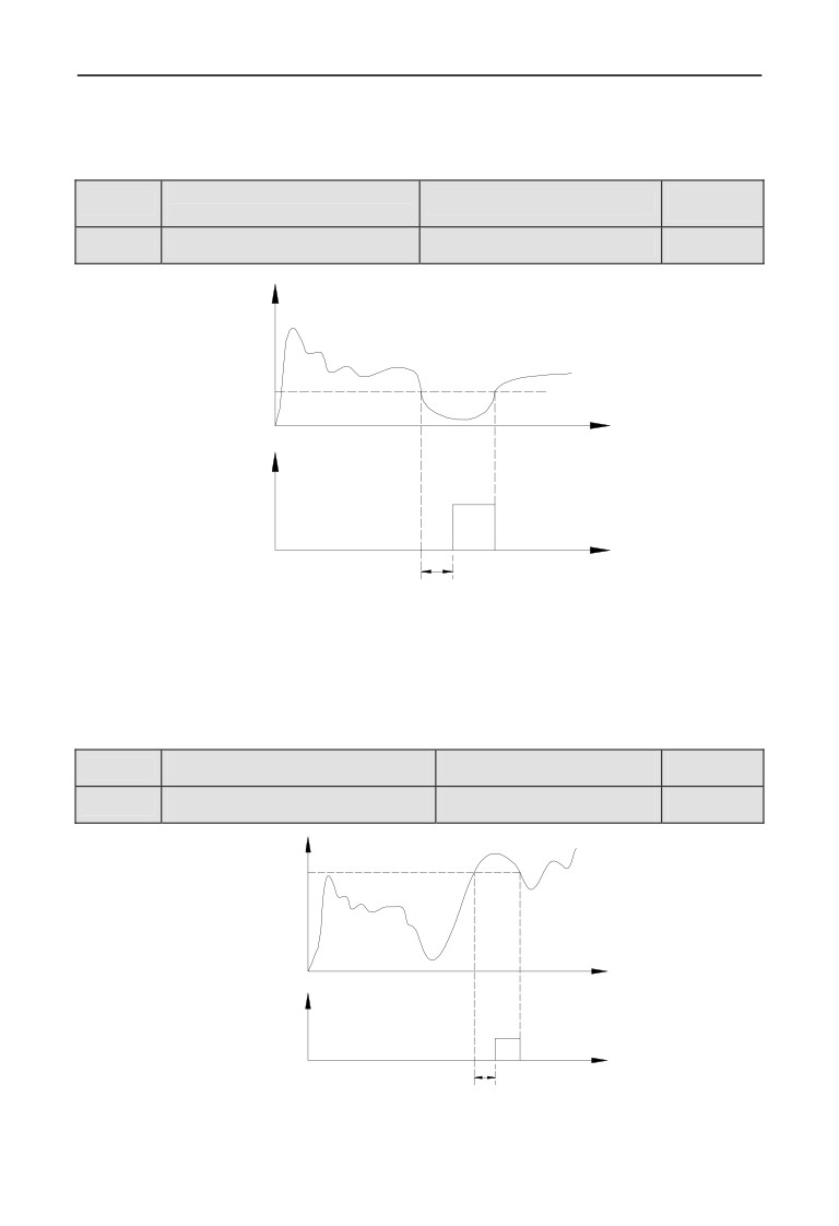
Zero current detection
F09.12
Range: 0.0~50.0%
0.0%
amplitude
F09.13
Zero current detection time
Range: 0.00~60.00s
0.1s
Output current
Zero current
detection amplitude
(F09.12)
Time
Zero current
detection signal
Time
Zero current
detection time
(F09.13)
Fig.7-26 Zero current detection diagram
When the output current of the inverter is less than or equal to zero current
detection level, and lasts longer than the zero current detection time, then the
output of frequency inverter multifunction Yi is indication signal. Figure 7-26 is
the schematic of zero current detection.
F09.14
Over-current detection value
Range: 0.0~250.0%
160.0%
F09.15
Over-current detection time
Range: 0.00~60.00s
0.00s
Output current
Output over
current detection
value(F09.14)
Time
Output over
current induction
signal
ON
Time
Output over
current detection
time(F09.15)
Fig.7-27 Output over-current detection diagram
155
7 Detailed function specification
When the output current of the inverter is greater than the over-current detection
points, and lasted longer than the over-current detection time, frequency inverter
multifunction Yi output indication signal, Figure 7-27 is the schematic of output
over-current detection.
Current 1 arriving the
F09.16
Range: 0.0~250.0%
100.0%
detection value
F09.17
Current 1 width
Range: 0.0~100.0%
0.0%
Current 2 arriving the
F09.18
Range: 0.0~250.0%
100.0%
detection value
F09.19
Current 2 width
Range: 0.0~100.0%
0.0%
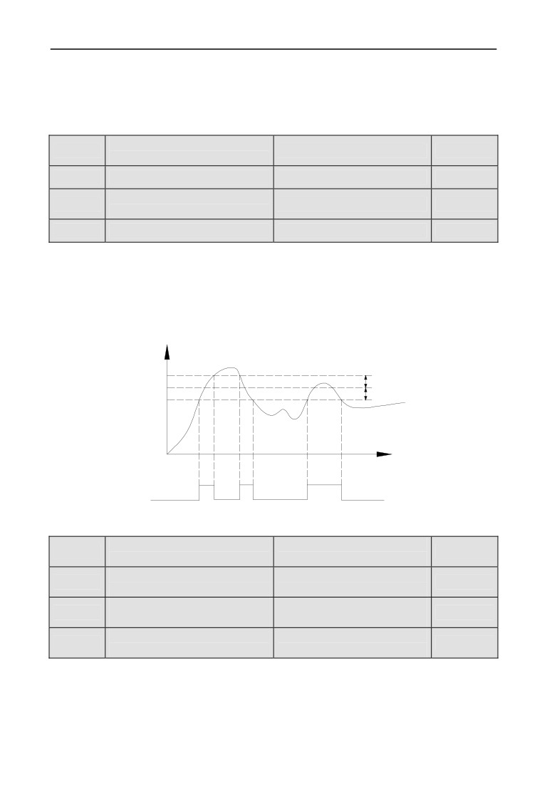
When the output current of frequency inverter is within the positive and negative
detection width of setting current arrival, then the output of frequency inverter
multifunction Yi is indication signal.
EN500/EN600 provides two current arrival and detection width parameters, table
7-28 is the function schematic diagram.
Output current
Current I arriving
Current I arriving detection width
detection value
Current I arriving detection width
Time
Current I arriving
ON
ON
ON
induction signal
OFF
OFF
OFF
Fig.7-28 Current arriving detection diagram
Frequency 1 arriving
Range:0.00Hz~upper
F09.20
50.00Hz
detection value
limit frequency
Frequency 1 arriving
Range:0.00Hz~upper
F09.21
0.00Hz
detection width
limit frequency
Frequency 2 arriving
Range:0.00Hz~upper
F09.22
50.00Hz
detection value
limit frequency
Frequency 2 arriving
Range:0.00Hz~upper
F09.23
0.00Hz
detection width
limit frequency
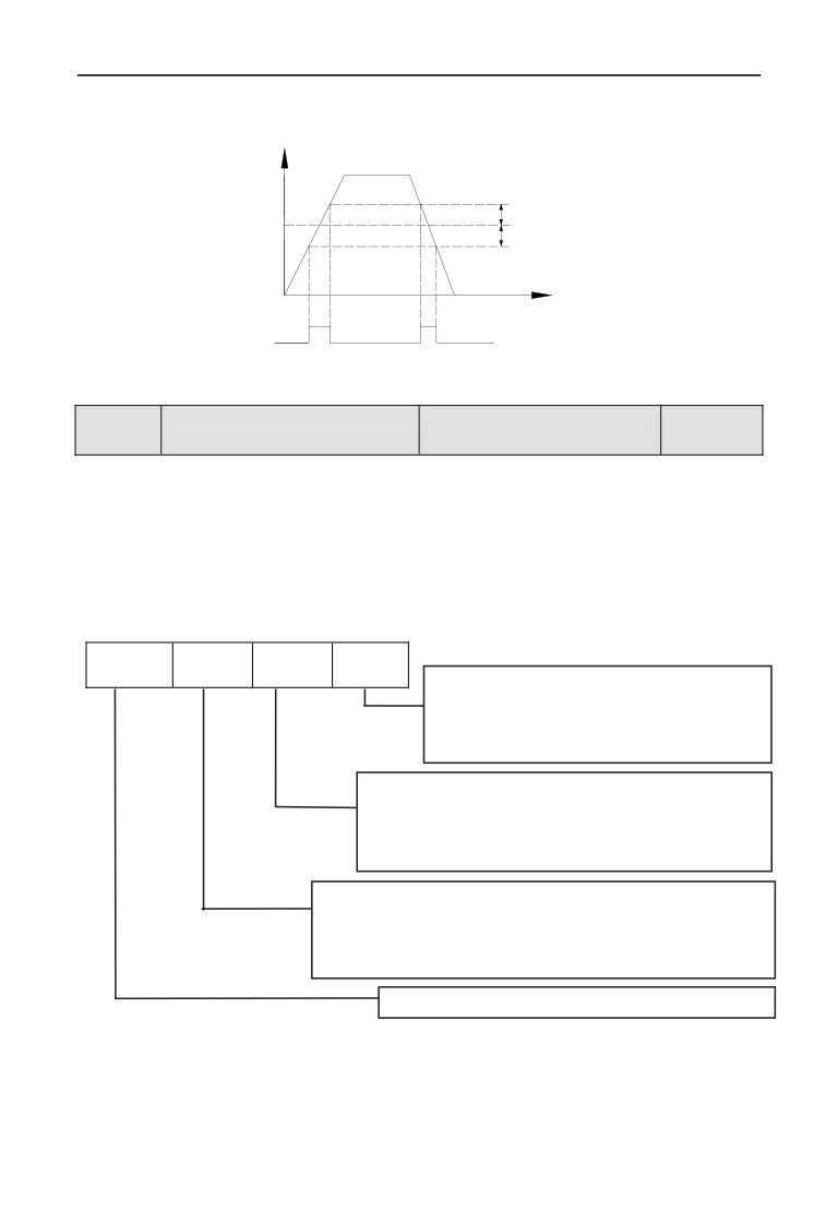
When the output frequency of frequency inverter reaches detecting value of the
positive and negative detecting width range, then the output of multifunctional Yi
is indication signal.
EN500/EN600 provides two sets of frequency arrival detecting parameters, which
have set frequency value and frequency detecting width respectively. Table 7-29
156
7 Detailed function specification
is the diagram of this function.
Operating freq.
Frequency I arriving detection width
Frequency I arriving
detection value
Frequency I arriving detection width
Time
Frequency I arriving
ON
ON
induction signal
OFF
OFF
OFF
Fig.7-29 Frequency arriving detection diagram
Positive and negative logic
F09.24
Range: 0000~FFFF
0000
setting of output terminal
This parameter defines the output logic of the standard output terminal Yi, relay
RLY and expand output terminal EYi, relays ERIY1, ERLY2.
0: positive logic, output terminal and the common terminal close to the valid
state, disconnect invalid state
1: reverse logic, output terminal and the common terminal close to the
invalid state, disconnect valid state
thousands
hundreds
The tens
the units
BIT0:Y1 positive and negative logic definition
BIT1:Y2 positive and negative logic definition
BIT2:Y3 positive and negative logic definition
BIT3:Y4 positive and negative logic definition
BIT0: fault relay 1 positive and negative logic definition
BIT1:expand OC1 positive and negative logic definition
BIT2:expand OC2 positive and negative logic definition
BIT3:expand OC3 positive and negative logic definition
BIT0:expand OC4 positive and negative logic definition
BIT1:expand fault relay1 positive and negative logic definition
BIT2:expand fault relay2 positive and negative logic definition
BIT3: reserved
BIT0~BIT3: reserved
157
7 Detailed function specification
F09.25
Y1 output closed delay time
Range: 0.000~50.000s
0.000s
Y1 output disconnected
F09.26
Range: 0.000~50.000s
0.000s
delay time
F09.27
Y2 output closed delay time
Range: 0.000~50.000s
0.000s
Y2 output disconnected
F09.28
Range: 0.000~50.000s
0.000s
delay time
F09.29
Y3 output closed delay time
Range: 0.000~50.000s
0.000s
Y3 output disconnected
F09.30
Range: 0.000~50.000s
0.000s
delay time
F09.31
Y4 output closed delay time
Range: 0.000~50.000s
0.000s
Y4 output disconnected
F09.32
Range: 0.000~50.000s
0.000s
delay time
Relay output closed delay
F09.33
Range: 0.000~50.000s
0.000s
time
Relay output disconnected
F09.34
Range: 0.000~50.000s
0.000s
delay time
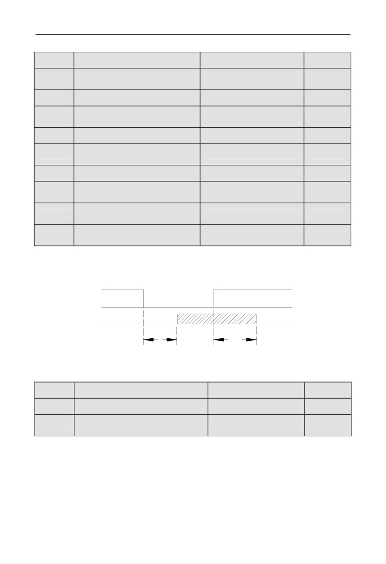
Parameter F09.25 ~ F09.34 defines the corresponding delay time from connect or
disconnect to frequency level of the multifunction output terminals. Table 7-30 is
the schematic of multi-function output terminal operation.
Yi level
Invalid
Valid
Invalid
Yi Valid
close delay
Disconnect delay
Setting rang:0.000~50.000s
Fig.7-30 Multifunction output terminal action diagram
F09.35
Analog output (AO1) selecting
Range: 0~25
0
F09.36
Analog output (AO2) selecting
Range: 0~25
0
DO function selecting(reuse
F09.37
Range: 0~25
0
with Y4)
0:output frequency before slip compensation(0.00Hz~ upper limit
frequency)
1:output frequency after slip compensation(0.00Hz~ upper limit
frequency)
2: setup frequency(0.00Hz~ upper limit frequency)
3:master setup frequency(0.00Hz~ upper limit frequency)
4:auxiliary setup frequency(0.00Hz~ upper limit frequency)
158
7 Detailed function specification
5:current output 1(0~2×rated current of frequency inverter)
6:current output 1(0~3×rated current of frequency inverter)
7:output voltage(0~1.2×rated voltage of load motor)
8: bus voltage (0~1.5×Rated bus voltage)
9:motor speed(0~3 ×rated speed)
10:PID given(0.00~10.00V)
11:PID feedback(0.00~10.00V)
12:AI1(0.00~10.00V or 4~20mA)
13:AI2(-10.00~10.00V or 4~20mA)
14: communication given(AO output is controlled by communication,
please refer to the related communication protocol for details.)
15:motor rotate speed (0.00Hz~upper limit frequency)
16:current given torque (0~2 times of rated torque)
17:current output torque(0~2 times of rated torque)
18:current torque current(0~2 times of rated motor current)
19:current flux current(0~1 times of rated motor flux current)
20~25:reserved
1.Terminal AO1 and AO2 are optional output terminal of 0~10V
or 4~20mA which can satisfy the variety needs of customer.
2.By disposing F00.21 analog output,output of terminal AO1 and
AO2 can be 0~10V or 4~20mA to satisfy the variety needs of
customer.
Note
3.The unit’s place of F00.22 is set to 1 when DO output pulse signal.
4.Rated flux current=current value of F15.11 parameter.
Rated torque current=sqrt (rated motor current×rated motor
Current-rated flux current×rated flux current)
F09.38
Reserved
F09.39
Analog output (AO1) filter time
Range: 0.0~20.0s
0.0s
F09.40
Analog output (AO1) gain
Range: 0.00~2.00
1.00
F09.41
Analog output (AO1) bias
Range: 0.0~100.0%
0.0%
Parameter F09.39 defines the filter time of A01 output, its reasonable setting can
improve stability of analog output. But a higher setting will influence the rate of
change, which can not reflect the instantaneous value of corresponding physical
quantity.
159
7 Detailed function specification
If users want to change the display range or error correction table headers, you can
achieve it by adjusting the output gain and bias of AO1.
When AO1 output voltage, the adjustment is as follows:
Analog output AO1(after revise)=output gain(F09.40)×analog output AO1(before
revise)+output bias(F09.41)×10V
When AO1 output current, the adjustment is as follows:
Analog output AO1(after revise)=output gain(F09.40)×analog output AO1(before
revise)+output bias(F09.41)×20mA
This function code will influence analog output during modify
processes.
Note
F09.42
Analog output (AO2) filter time
Range: 0.0~20.0s
0.0s
F09.43
Analog output (AO2) gain
Range: 0.00~2.00
1.00
F09.44
Analog output (AO2) bias
Range: 0.0~100.0%
0.0%
Please refer to the function introduce of parameters F09.39~F09.41
F09.45
DO filter time
Range: 0.0~20.0s
0.0s
F09.46
DO output gain
Range: 0.00~2.00
1.00
DO maximum pulse output
F09.47
Range: 0.1~20.0KHz
10.0KHz
frequency
Please refer to the function introduce of parameters F09.39~F09.41.
Maximum pulse output frequency of terminal DO corresponds to maximum select
value of F09.37. For example, F09.31=0, terminal DO’s function is: output
frequency before slip compensation, which means Maximum pulse output
frequency corresponds to upper frequency.
F09.48
Reserved
F09.49
Reserved
F09.50
Reserved
160
7 Detailed function specification
7.11 Simple PLC/Multi-speed function parameters Group:F10
Range: unitdigit: 0~3
tens digit: 0~2
F10.00
Simple PLC operate setting
0000
hundreds digit: 0,1
thousands digit: 0,1
The simple PLC operation mode, re-start mode after interruption, unit of running
time and the storage mode when power off can be set in different bit of parameter
F10.00, details as follows:
Unit digit: simple PLC operation mode.
0:No action.PLC operation mode is disabled.
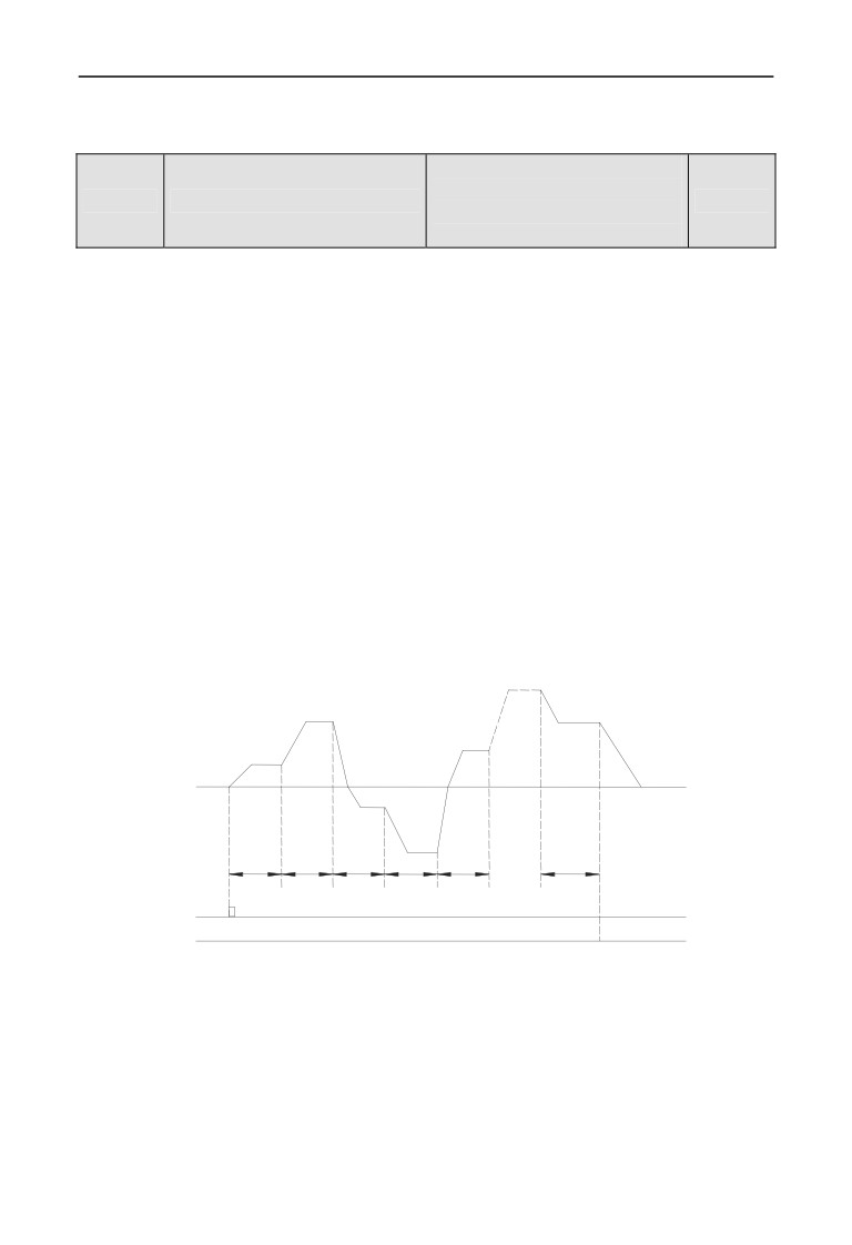
1:Stop after single cycle. as show in Fig.7-31, the drive stops automatically
after one cycle of operation and will not start only when receiving RUN command
again.
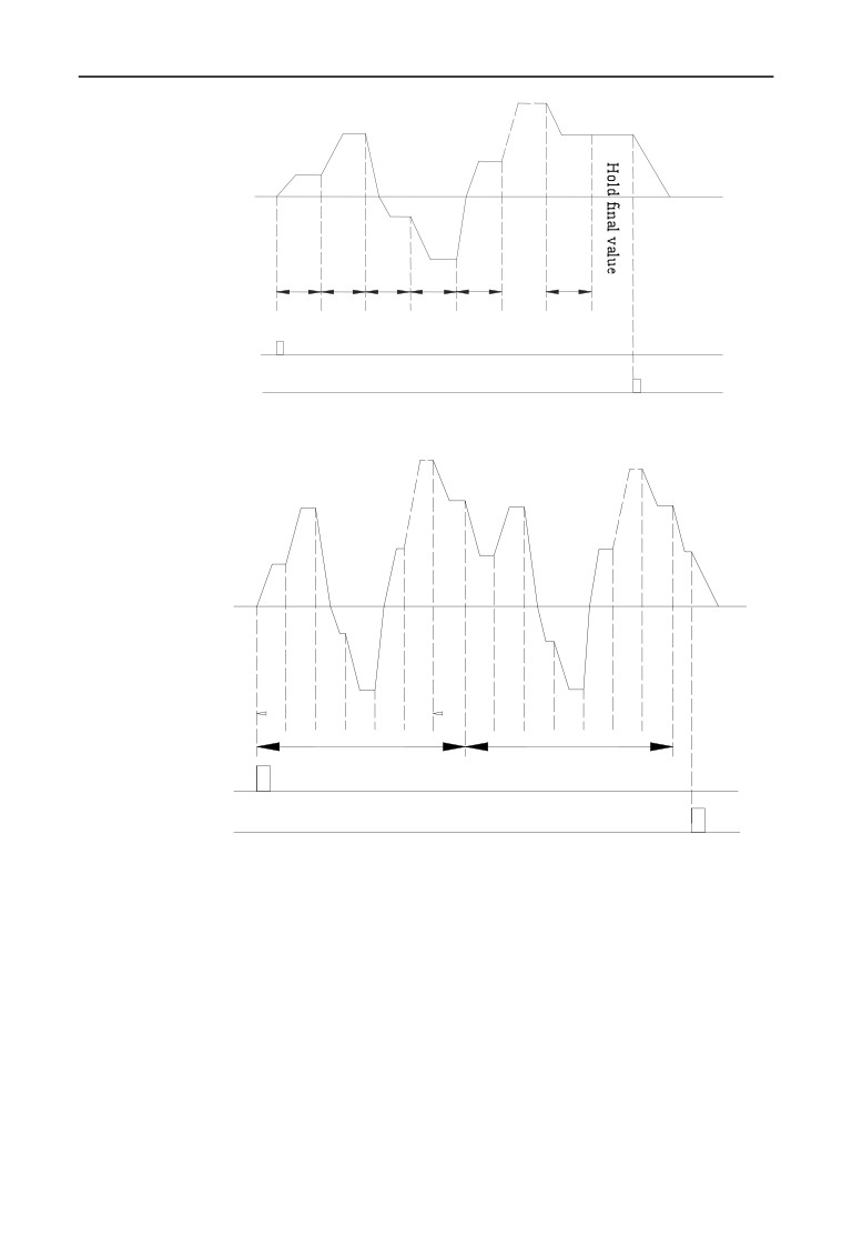
2: Maintain final value after one cycle, as show in Fig.7-32, the drive will
keep running with the final value and the direction after complete one cycle
operation, the drive won’t stop according to the set stop mode until the stop
command is available.
3: Continuous operation, as show in Fig.7-33, the drive will start next cycle
of operation automatically after completing one cycle of operation until receiving
STOP command then stop according the set stop mode.
15
d
f
2
f
15
a
2
f
5
f
1
d
3
a
1
a
5
a
3
f
3
a4
d
5
f
4
T15
T1
T2
T3
T4
T5
RUN Command
STOP Command
Fig.7-31 PLC stop operating after one cycle mode
161
7 Detailed function specification
d15
f
2
f15
a
2
f
5
f
1
d
3
a
1
a5
a3
f3
5
d
a
4
f4
T1
T2
T3
T4
T5
T15
RUN Command
STOP Command
Fig.7-32 PLC holds the final value after one cycle mode
d15
d
15
f2
f15
f2
f15
a2
d1
a2
d1
f5
f5
d2
f1
f1
f1
d3
a5
a5
a1
PLC Operation
a3
a3
f3
f3
d4
d4
a4
a4
f4
f4
T1 T2 T3 T4 T5
T15 T1 T2 T3 T4 T5
T15
The first cycle
The second cycle
RUN Command
STOP Command
Fig7-33 PLC continuous operation mode
a1~a15:The Acc time of different steps
d1~d15:The Dec time of different steps
f1~f15:The frequency of different steps
There are 15 steps can set in Fig.7-31,7-32,7-33.
Tens digit: Restart mode after interruption.
0: Restart from the first step.
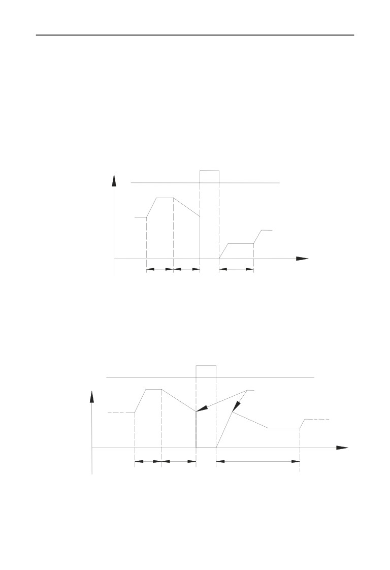
If the drive stops during PLC operation due to receiving STOP commands, fault
alarm or power failure, it will run from the first step after restarting.
1: Restart from the interruption step;
If the drive stops during PLC operation due to receiving STOP command or fault
162
7 Detailed function specification
alarm, the drive will record the operating time of the current step and will
continue from the step where the drive stops after restart at the frequency defined
for this step with the remained time, as show in Fig.7-34.If the drive stops due to
power off, it will not record the state and from the first step operate when restart.
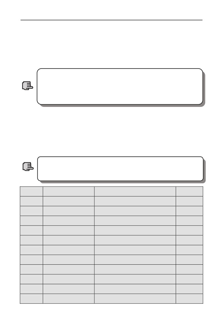
2: Restart from the interrupted Frequency
If the drive stops during PLC operation due to receiving STOP command or fault
alarm, the drive will record the operating time and the current frequency of the
interrupt step, it will operating with the record time and record frequency when
restart, as show in Fig7-35
Output Freq. Hz
Pause signal
f1
d
2
a1
f3
a 3
f2
a2
Time t
Step1
Step2
Operated time
Step2 remain time
a1:Acc time of the 1st step
a2:Acc time of the 2nd step
a3:Acc time of the 3rd step
d2:Dec time of the 1st step
f1:Frequency of the 1st step
f2:Frequency of the 2nd step
f3:Frequency of the 3rd step
Fig.7-34 simple PLC restart mode 1
Pause signal
f1
Output Freq Hz
Same freq.
a1
d2
f3
d2
a
a2
f2
3
Time t
Step1
Step2
Step 2 remain time
Operated time
a1:Acc time of the 1st stepa2:Acc time of the 2nd step
a3:Acc time of the 3rd step
d2:Dec time of the 1st step
f1:Frequency of the 1st step
f2:Frequency of the 2nd step
f3:Frequency of the 3rd step
Fig.7-35 PLC Restart mode 2
163
7 Detailed function specification
Hundreds digit: PLC unit of running time.
0: Seconds;
1: Minutes;
The unit is effective for the running time of different steps only, during the operation
of PLC, the unit of Acc time and Dec time is defined by parameter F01.19.
1. The step is ineffective if the time of this step of PLC operation is
set as 0 thereafter operate the next step.
2.Control the PLC process a pause
,ineffective, operate via
Note
terminal ,for details please refer to parameters in F8 Group that
relative with terminal function.
Thousands digit: the storage mode when power off.
0: No storage. No record the running state when power off, it will restart
from the first step when power on again.
1: Storage. Records the running status which include the step, running
frequency and running time when power off, it restart with the mode that set in
hundreds digit after power on again.
No matter power-off storage in stop status or running status, you
should set thousands digit as 1 thereafter set tens digit as 1 or
Note
2,otherwise power-off storage function is ineffective.
F10.01
Step 1 setting
Range: 000H~E22H
000
F10.02
Step 2 setting
Range: 000H~E22H
000
F10.03
Step 3 setting
Range: 000H~E22H
000
F10.04
Step 4 setting
Range: 000H~E22H
000
F10.05
Step 5 setting
Range: 000H~E22H
000
F10.06
Step 6 setting
Range: 000H~E22H
000
F10.07
Step 7 setting
Range: 000H~E22H
000
F10.08
Step 8 setting
Range: 000H~E22H
000
F10.09
Step 9 setting
Range: 000H~E22H
000
F10.10
Step 10 setting
Range: 000H~E22H
000
F10.11
Step 11 setting
Range: 000H~E22H
000
F10.12
Step 12 setting
Range: 000H~E22H
000
164
7 Detailed function specification
F10.13
Step 13 setting
Range: 000H~E22H
000
F10.14
Step 14 setting
Range: 000H~E22H
000
F10.15
Step 15 setting
Range: 000H~E22H
000
F10.01~F10.15 are used to configure the operating frequency, direction and
Acc/Dec time of each PLC operating step. These functions are all selected by
digits on different place of parameters. Details as below:
Unit digit: Frequency setting
0:select multi-frequency i. i=1~15,please refer to F10.31~F10.45 for
definitions of multi-frequency.
1:the frequency is determined by the combination of the main frequency
and the auxiliary frequency.
2: Reserved.
Tens digit: Direction choosing
0: Forward.
1: Reversed.
2: Determined by operating commands (FWD, REV)
Hundreds digit: Acc/Dec time choose
0: Acc/Dec time 1
1: Acc/Dec time 2
2: Acc/Dec time 3
3: Acc/Dec time 4
4: Acc/Dec time 5
5: Acc/Dec time 6
6: Acc/Dec time 7
7: Acc/Dec time 8
8: Acc/Dec time 9
9: Acc/Dec time 10
A: Acc/Dec time 11
B: Acc/Dec time 12
C: Acc/Dec time 13
D: Acc/Dec time 14
E: Acc/Dec time 15
Accelerate time1~15 defined by F01.17,F01.18,F04.16~F04.43
F10.16
Step 1 running time
Range: 0~6000.0
10.0
F10.17
Step 2 running time
Range: 0~6000.0
10.0
F10.18
Step 3 running time
Range: 0~6000.0
10.0
165
7 Detailed function specification
F10.19
Step 4 running time
Range: 0~6000.0
10.0
F10.20
Step 5 running time
Range: 0~6000.0
10.0
F10.21
Step 6 running time
Range: 0~6000.0
10.0
F10.22
Step 7 running time
Range: 0~6000.0
10.0
F10.23
Step 8 running time
Range: 0~6000.0
10.0
F10.24
Step 9 running time
Range: 0~6000.0
10.0
F10.25
Step 10 running time
Range: 0~6000.0
10.0
F10.26
Step 11 running time
Range: 0~6000.0
10.0
F10.27
Step 12 running time
Range: 0~6000.0
10.0
F10.28
Step 13 running time
Range: 0~6000.0
10.0
F10.29
Step 14 running time
Range: 0~6000.0
10.0
F10.30
Step 15 running time
Range: 0~6000.0
10.0
Parameters F10.16~F10.30 defined Running time of each PLC Step from Step 1
to Step 15.
Each step running time include Acc time and Dec time.
Note
F10.31
Multi-Frequency 1
Range:0.00Hz~upper limit Freq.
5.00Hz
F10.32
Multi-Frequency 2
Range:0.00Hz~upper limit Freq.
10.00Hz
F10.33
Multi-Frequency 3
Range:0.00Hz~upper limit Freq.
20.00Hz
F10.34
Multi-Frequency 4
Range:0.00Hz~upper limit Freq.
30.00Hz
F10.35
Multi-Frequency 5
Range:0.00Hz~upper limit Freq.
40.00Hz
F10.36
Multi-Frequency 6
Range:0.00Hz~upper limit Freq.
45.00Hz
F10.37
Multi-Frequency 7
Range:0.00Hz~upper limit Freq.
50.00Hz
F10.38
Multi-Frequency 8
Range:0.00Hz~upper limit Freq.
5.00Hz
F10.39
Multi-Frequency 9
Range:0.00Hz~upper limit Freq.
10.00Hz
F10.40
Multi-Frequency 10
Range:0.00Hz~upper limit Freq.
20.00Hz
F10.41
Multi-Frequency 11
Range:0.00Hz~upper limit Freq.
30.00Hz
F10.42
Multi-Frequency 12
Range:0.00Hz~upper limit Freq.
40.00Hz
166
7 Detailed function specification
F10.43
Multi-Frequency 13
Range:0.00Hz~upper limit Freq.
45.00Hz
F10.44
Multi-Frequency 14
Range:0.00Hz~upper limit Freq.
50.00Hz
F10.45
Multi-Frequency 15
Range:0.00Hz~upper limit Freq.
50.00Hz
Frequency will be used in Multi-speed operation mode and Simple PLC operation
mode. More details please refer to the Multi-speed terminal operation function in
Parameters Group F08 and Simple PLC operation function in Parameters Group
F10.
167
7 Detailed function specification
7.12 Closed-Loop PID operation Parameters Group:F11
Analog feedback control system:
Pressure reference is input through the terminal AI1,and water pressure sensor
send a 4-20mA to the terminal AI2 of inverter as a feedback signal, all of them
make up of analog closed-loop control system via build-in PID adjuster ,as shown
in Fig.7-36
QF
Three
EN500/EN600
Output
R
U
phase
S
V
M
P
380V
T
W
Xi (Defined as FWD)
COM
4~20mA
AI2
+10V
GND
Provision
AI1
1~3K
GND
Fig.7-36 Build-in PID adjuster control system diagram
Setting the value of F11.01 can choose the channel of pressure
reference.
Note
Operating principle of built-in PID function of EN500/EN600 is shown in
Fig.7-37 as below:
Proportion
gain
(F11.07)
+
e
Reference
Offset limit
+
Closed-loop
Closed-loop
Integral gain
regulation
output
Closed-loop
reference
(F11.03)
_
(F11.11)
(F11.08)
regulation
output
+
Differential
gain
Feedback
(F11.09)
regulation
Closed-loop feedback
(F11.04,F11.14)
Fig.7-37 PID block control principle diagram
In above diagram ,the definition of closed-loop reference ,feedback error limit and
PI parameters are similar with the general PID adjuster,the relationship between
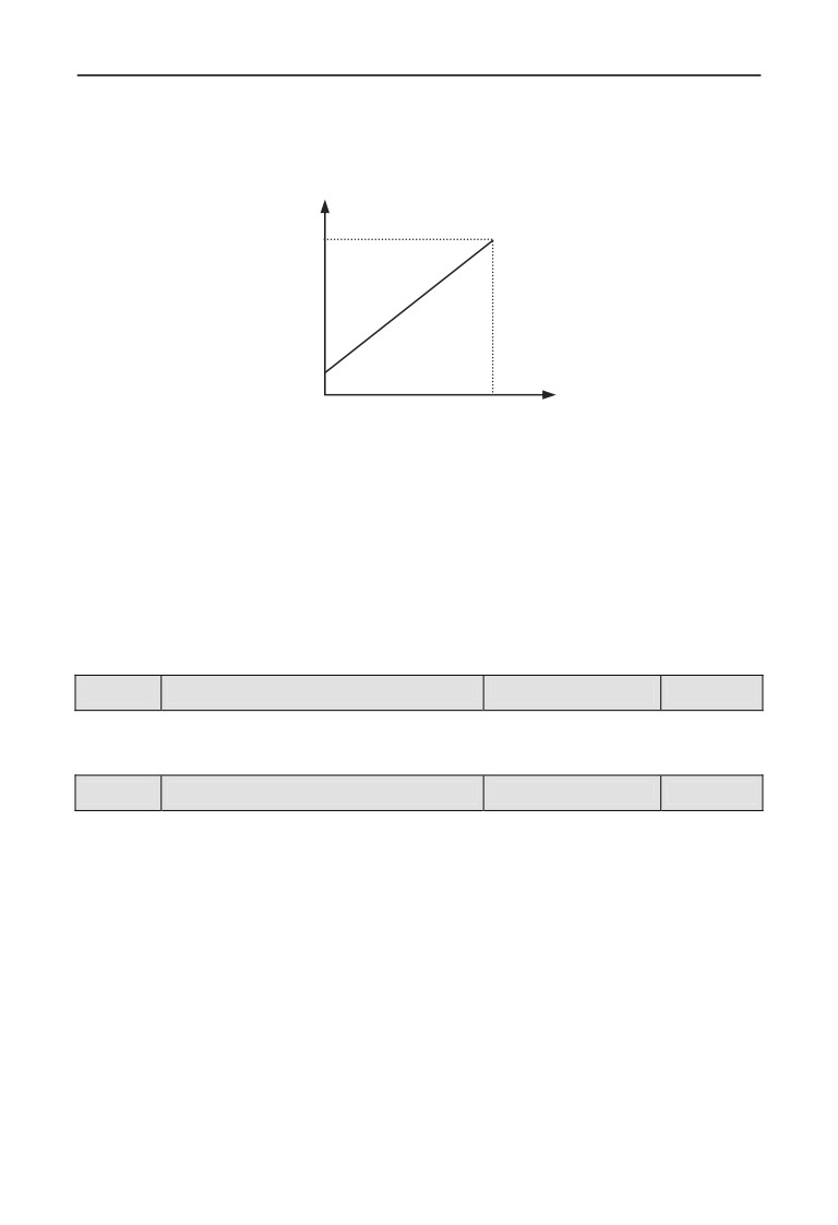
reference and expected feedback is shown in Fig.7-38.The reference and feedback
168
7 Detailed function specification
are converted and based on 10.00V.
In Fig.7-37, the real values of closed-loop reference and feedback can be
regulated in Group F06 and F07, so that can reach a good performance.
Expected Value eedback
20mA
4mA
Pressure reference
0
10V
Fig.7-38 Reference and expected feedback value
After the system control mode is confirmed, follow the procedures below to set
the closed-loop parameters:
(1)Determine the closed-loop reference and feedback channel (F11.01F11.02).
(2)The relationship between the closed-loop reference and feedback should be
defined for closed-loop control (the Group F6).
(3) Set up the closed-loop frequency presetting function (F11.19,F11.20).
(4) Adjust the proportion gain, integral gain, differential gain, sampling cycle and
error limit(F11.07~F11.11).
F11.00
Closed-loop control function
Range: 0,1
0
0:PID closed-loop function disabled
1:PID closed-loop function enabled
F11.01
Reference channel choose
Range: 0~7
0
0: Digital provision
1:AI1 analog 0-10V or 4-20mA provision
2:AI2 analog provision
3:EAI1 analog provision (Extensible)
4:EAI2 analog provision (Extensible)
5: Pulse provision
6: Communication provision(Please refer to the chapter of Modbus
communication)
7: Reserved
169
7 Detailed function specification
Except the above provision channels, Multi-Closed-loop provision
is available. Connecting different terminal to choose different
Note
provision value which with a highest priority.
F11.02
Feedback channel selection
Range: 0~8
0
0:AI1 analog input
1:AI2 analog input
2:EAI1 analog input(Extensible)
3:EAI2 analog input(Extensible)
4:AI1+AI2
5:AI1-AI2
6:Min{AI1,AI2}
7:Max{AI1,AI2}
8: Pulse input
F11.03
Provision channel filtering time
Range: 0.01~50.00s
0.20s
F11.04
Feedback channel filtering time
Range: 0.01~50.00s
0.10s
F11.05
PID output filtering time
Range: 0.00~50.00s
0.00s
The external reference signal and feedback signal usually carry some noise. those
noise signal can be filtered by setting the time constant of filter in F11.03 and
F11.04.The bigger the time constant is, the better the immunity capability, but
with a slow response. The shorter the time constant is, the faster the response, but
the immunity capability became weak.
The PID output filter time is the time of the filter for output frequency or torque,
the bigger time, the slower the response output.
F11.06
Provision digital setting
Range: 0.00~10.00V
1.00V
This function can realize digital setting of reference via keypad.
When the PID function is enabled, Setting F18.14 as 1 can adjust
pressure reference by press
, otherwise the
keys
Note
are invalid for adjusting reference in monitoring mode.
F11.07
Proportion Gain Kp
Range: 0.000~9.999
0.100
F11.08
Integral Gain Ki
Range: 0.000~9.999
0.100
F11.09
Differential Gain Kd
Range: 0.000~9.999
0.000
170
7 Detailed function specification
F11.10
Sampling cycle T
Range: 0.01~1.00s
0.10s
The bigger of the proportion gain of Kp, the faster the response, but oscillation
may easily occur.
If only proportion gain Kp is used in regulation, the offset cannot be eliminated
completely. To eliminate the offset, please use the integral gain Ki to form a PI control
system. The bigger Ki is, the faster the response, but oscillation may easily occur if Ki is
big enough.
The sampling cycle T refers to the sampling cycle of feedback value. The PI D
regulator calculates once in each sampling cycle. The bigger the sampling cycle is,
the slower the response.
F11.11
Deviation limit
Range: 0.0~20.0%
2.0%
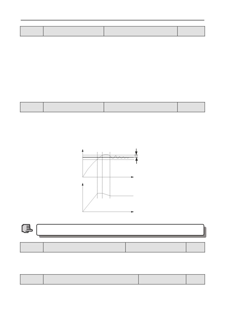
If defines the max. Deviation of the output from the reference, as shown in Fig.7-39,
the PID adjuster stops operation when the feedback value within this range. Setting
this parameter correctly will improve the moderation of the accuracy and stability of
the system
Feedback
Reference
Offset limit
Time
Output Freq.
Time
Fig.7-39 Offset limit
Offset limit is the percentage refer to the value of reference.
Note
F11.12
PID differential amplitude limit
Range: 0.00~100.00%
0.10%
In the PID regulator, the effect of differential is too sensitive too easy to cause
system oscillation, therefore limit the effect of differential PID in a smaller range,
F11.12 the parameter that used to set the output range of PID differential.
F11.13
Closed-loop regulation characteristic
Range: 0,1
0
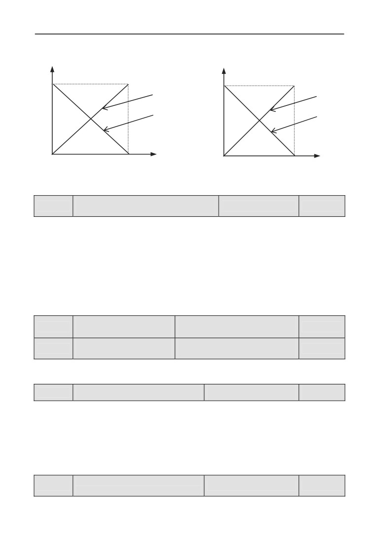
0: Positive effect. When the provision increases, select while requiring speed
of motor increase.
1: Negative effect. When the provision increases, select while requiring
171
7 Detailed function specification
speed of motor decrease.
Value after
converted
Speed
10V
Positive Effect
Positive Effect
Negative Effect
Negative Effect
Reference
Feedback
0
10V
0
10V
Fig.7-40 Closed-loop characteristic
Fig.7-41 Feedback characteristic
Feedback channel positive-negative
F11.14
Range: 0,1
0
characteristic
0: Positive characteristic. The relationship between reference and feedback
is positive
1: Negative characteristic. The relationship between reference and feedback
is negative
This parameter is used to change the feedback characteristic of the feedback
signal. After input into inverter through the feedback channel, the feedback
pressure will compare with the reference after regulated by the positive and
negative characteristic regulation, as shown in Fig.7-41
PID regulation upper
Range: 0.00Hz~upper limit
F11.15
50.00Hz
limit frequency
Frequency
PID regulation lower
Range: 0.00Hz~upper limit
F11.16
0.00Hz
limit frequency
Frequency
User can set up the parameters F11.15 and F11.16 to define the output lower limit
and upper limit frequency of the PID regulator.
F11.17
Integral regulation selection
Range: 0,1
0
0: Stop integral regulating when the comparison value of the reference and
feedback reaches the range of threshold for integral separation
1: Keep integral regulating even thought the comparison value of the
reference and feedback reach the range of threshold integral separation
Adjusting this parameter can avoid integral saturation and improve the response
of the system.
PID threshold of the integral
F11.18
Range: 0.0~100.0%
100.0%
separation
PID integral separated function: there is no integral regulating just proportion
regulating during closed-loop control when the comparison value that between
172
7 Detailed function specification
reference and feedback is bigger than this threshold. When the comparison is
smaller than this threshold, the integral regulating will be active, and can adjust
the response speed of system by adjusting this parameter.
Preset Closed-loop
Range: 0.00Hz~upper
F11.19
0.00Hz
frequency
limit frequency
Holding time of preset
F11.20
Range: 0.0~6000.0s
0.0s
Closed-loop frequency
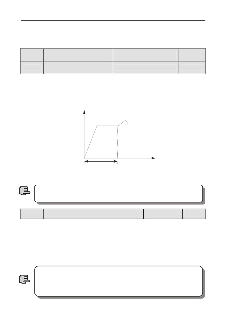
This function can make the closed-loop adjuster into the stable status quickly.
When the closed-loop function start,the output frequency will ramp up to the preset
closed-loop frequency(F11.19) within the Acc time, and keep running the time that set
in F11.20 then start the closed-loop operation as shown is Fig.7-42
Output Freq.
Preset Freq.
Time
Hold time of Preset Freq.
Fig.7-42 Preset closed-loop operating
Preset closed-loop Function is ineffective when set F11.19 and
F11.20 as 0.
Note
F11.21
Closed-loop output reversion selection
Range: 0~2
2
0: The inverter will runs with the low limit frequency when the closed-loop
output value is negative
1:The inverter will reverse running when the value of the closed-loop output
is negative(be opposite of the initial direction )
2: determined by running demand. The motor running direction is
determined by demand direction.
The comparison value can be display in the PID monitor
parameters, it’s positive when the reference bigger than the
feedback value, and negative when reference smaller than
Note
feedback value.
173
7 Detailed function specification
Closed-loop output
Range: 0.00Hz~upper limit
F11.22
reversion frequency
50.00Hz
Frequency
upper limit
The PID regulator is a kind of bipolar adjustment. By setting F11.21 and F11.22,
can choose whether the inverter reverse run in some degree frequency or not.
F11.23
Multiple closed-loop provision 1
Range: 0.00~10.00V
0.00V
F11.24
Multiple closed-loop provision 2
Range: 0.00~10.00V
0.00V
F11.25
Multiple closed-loop provision 3
Range: 0.00~10.00V
0.00V
F11.26
Multiple closed-loop provision 4
Range: 0.00~10.00V
0.00V
F11.27
Multiple closed-loop provision 5
Range: 0.00~10.00V
0.00V
F11.28
Multiple closed-loop provision 6
Range: 0.00~10.00V
0.00V
F11.29
Multiple closed-loop provision 7
Range: 0.00~10.00V
0.00V
Among the closed-loop reference channel, besides the 7 channels defined by
F11.01,the closed-loop reference can also be defined in F11.23~F11.29. The
priority of multi-closed-loop reference control is higher than the reference
channels that defined by F11.01.
Multi-closed-loop reference 1~7 can be selected by external terminals. Please
refer to the terminal function 19~21 of introductions to F08.18~F08.25.When the
function of Constant water supply is enable, the reference of constant water
pressure is decided by the multi-closed-loop reference which selected by external
terminals.
Computational formula: constant pressure reference = F12.06 × Multi-closed-loop
reference/10.00V.By using this functions can realize different times with a
different constant water pressure.
174
7 Detailed function specification
7.13 Constant pressure water supply function parameters Group: F12
Constant pressure water supply mode
F12.00
Range: 0~4
0
selection
0: disabled.
1: Inverter works in one-drive-two-pump mode.
2: Choose extensible constant pressure board acts in one-drive-two-pump
mode.
3: Choose extensible constant pressure board acts in one-drive-three-pump
mode.
4: Choose extensible constant pressure board acts in one-drive-four-pump
mode.
This function can be used to choose different kinds of constant pressure water
supply mode, and you should choose an extensible constant pressure board to
realize one-drive-three mode and one-drive-four mode and F00.19 should be set to
2.
1. The function of Group F11 will be effective automatically when
the constant pressure supply function is enabled.
2. Except for the related parameters in Group F11 and F12 for
Closed-loop, the function of Yi should be enabled in F9 for the
inverter works in one-drive-two-pump mode without an extend
Note
board.
3. Output terminal Y4/DO should be set to Y4.
4. When one inverter drive one pump with constant pressure water
supply, the parameter F09.00~F09.03
(Y1~Y4) can not be set
37~38.
Range: 0.000~the range of
F12.01
Target pressure setting
0.200Mpa
long-distance manometer
This parameter defined the target pressure of the constant pressure supply system.
The channels of the pressure reference and feedback are defined by F11.01 and
F11.02.
Range: 0.00Hz~upper
F12.02
Sleep frequency threshold
30.00Hz
limit frequency
Range: 0.000~F12.06
F12.03
Revival pressure threshold
0.150Mpa
Mpa
The function of Sleep frequency threshold: To save energy and protect the motor,
when the water feedback pressure within the offset limit
(F11.11), and the
operating frequency is under in the sleep frequency threshold (F12.02), after a
sleep delay time (F12.04), the system will enter a sleep mode and the operating
frequency will drop to 0.00Hz
175
7 Detailed function specification
Revival function: When the system is in the sleep mode, if the feedback water
pressure keep less than F12.03 (the revival pressure) a delay time (F12.05), the
system will revival from the sleep mode.
F12.04
Sleep delay time
Range: 0.0~6000.0s
0.0s
This parameter is the delay time that from the feedback pressure meets the sleep
conditions to the system enter in sleep mode.
Within the sleep delay time, if the feedback pressure does not meet the sleep
conditions, the system will not enter into sleep mode
Sleep function is disabled when F12.04=0.
F12.05
Revival delay time
Range: 0.0~6000.0s
0.0s
When the constant pressure supply system in the sleep state, if the feedback
pressure of system less than F12.11 which defined the revival pressure
threshold ,the system will revival and get out of sleep mode after the revival delay
time.
The range of long-distance
F12.06
Range: 0.001~9.999Mpa
1.000Mpa
manometer
This parameter defines the range of long-distance manometer. Setting this
parameter can correspond to the maximum feedback pressure with the analog
feedback signal 10V or 20mA
Allowed deviation of upper
limit frequency or lower limit
F12.07
Range: 0.1~100.0%
1.0%
frequency when add or
reduce pump
When output frequency reaches the deviation range of upper limited frequency
and the feedback is less than given value, adding pumps judge is available. When
output frequency reaches the deviation range of lower limited frequency and the
feedback is more than given value, decreasing pumps judge is available.
When F12.07=0.0%, output frequency reach upper or lower limitation frequency
and the pressure meets the requirement, then decrease pumps is available.
F12.08
Pump switch judging time
Range: 0.0~999.9s
5.0s
When the output frequency up to the upper limit frequency (F11.15) but the
pressure still not meeting the requirement, the system will add pump after the
judging time.
When the output frequency down to the lower limit frequency (F11.16) but the
pressure still not meeting the requirement, the system will reduce pump after the
judging time.
Electromagnetic contactor
F12.09
Range: 0.1~10.0s
0.5s
switching delay time
176
7 Detailed function specification
This parameter defines the action delay time of magnetic control conductor when
it’s switch from power source supply to variable or from variable frequency
control to power source supply.
Automatic switching time
F12.10
Range: 0000~9999Mins
0
interval
By setting this parameter can avoid the rust of motor when it’s not work long time.
The inverter will switch the work status of the working pump and static pump
automatically and smartly under the switch interval.
The automatic switch function is disabled when set the parameter as 0000. The
system will switch one time when each restart of system as this parameter is 0001.
If the value of this parameter is bigger than
0002, the system will switch
automatically according the switch interval.
F12.11
Revival mode selection
Range: 0,1
1
F12.12
Revival pressure coefficient
Range: 0.01~0.99
0.75
When F12.11=0, the revival pressure of the constant pressure supply is the value
of F12.03.
WhenF12.11=1, the revival pressure is the calculating value of F12.12*F12.01
F12.13
Reserved
F12.14
Reserved
177
7 Detailed function specification
7.14 Traverse, Fixed-length control Function Parameters Group:
F13
F13.00
Traverse function selection
Range: 0,1
0
0: Disabled
1: Enabled
Range: unit digit: 0,1
tens digit: 0,1
F13.01
Traverse operating mode
0000
hundreds digit: 0,1
thousands digit: 0,1
Unit digit: Start mode 1st
0: Auto start. The drive operates at the preset frequency of traverse for a
certain time thereafter enter traverse mode automatically.
1: Terminal manual mode. Choosing multi-function terminal(Xi= X1~
X8)as 56 function, when the terminal is enabled, the drive will enter traverse
mode. The drive will exit traverse operation and operate at the pre-set traverse
frequency when it’s disabled.
Tens digit: Traverse amplitude AW mode choosing
0: Variable swing. Amplitude AW changes with the central frequency and
the change rate relate to the definition of F13.02.
1: Fixed swing. Traverse operating amplitude AW is determined by Upper
limit Frequency and F13.02.
Note: The traverse central frequency is set by the main frequency.
Hundreds digit: Restart mode
0: Restart at the initial state.
1: Restart at the memorized state before stopping
Thousands digit: Traverse state saving when power off.
This function is effective when the start mode is Restarting from the reserved
memory state, and saving operating state when power off.
0: Not save
1: Save
When in variable amplitude mode, the channel of central
frequency is confirmed by F01.06.During the traverse frequency
operation, the Acc and Dec time are controlled only by traverse
Note
frequency circle F13.04 when adjusting the central frequency.
178
7 Detailed function specification
F13.02
Traverse frequency swing value
Range: 0.0~50.0%
10.0%
Variable amplitude: AW= the central frequency ×F13.02
Fixed amplitude: AW=Upper limit frequency ×F13.02
The traverse operating frequency is restricted by the upper and
lower limit of frequency. Incorrectly setting the frequency will lead
Note
to abnormal of traverse operation.
F13.03
Sudden-jump frequency
Range:0.0~50.0%
2.0%
As shown in Fig.7-43, there is not a jitter frequency when F13.03=0.
F13.04
Traverse cycle
Range:0.1~999.9s
10.0s
F13.04 defines a complete cycle of traverse operation which including rising and
falling processed.
Triangular wave rising
Range:0.0~98.0%(Traverse
F13.05
50.0%
time
cycle)
Definition traverse rising time=F13.04×F13.05
(s), the traverse falling time=
F13.04×(1-F13.05)(s).
Please refer to Fig.7-43
F13.06
Preset frequency of Traverse
Range:0.00~400.00Hz
0.00Hz
F13.06 defines the operating frequency of the Drive before entering traverse
operation.
Traverse preset frequency
F13.07
Range:0.0~6000.0s
0.0s
waiting time
F13.07 defines the operating time of Preset frequency before entering Traverse
operation when auto-start mode is enabled.
If manual start mode is available, F13.07 is disabled.
Please refer to Fig.7-43 as below.
179
7 Detailed function specification
Hz Operating Fre.
Traverse amplitude
AW=Fset*F13.02
Upper Limit Freq
+AW
Central
Freq
-AW
Lower limit Freq
a1
Preset Freq
Jitter Freq
=AW*F13.03
a1
Time t
Rising time
Accelerate
Traverse waiting
Decelerate
Traverse Cycle
time=F13.07
according the Dec time
Run
Stop
Fig.7-43 Traverse operation
F13.08
Setting length
Range: 0~65535m
0m
Number of pulses for axis
F13.09
Range: 1~10000
1
per circle
F13.10
Perimeter of shaft
Range: 0.01~100.00cm
10.00cm
F13.11
Reserved
Correction coefficient of
F13.12
Range: 0.001~1.000
1.000
length
Set length, Actual length and Numbers of pulses per cycle are used for fixed
length control.
The Actual length is calculated by the number of pulses collected by terminal
Xi(i=1~8).
Allocate corresponding Xi terminal with 62(Length count input).
Actual length=(The number of Pulses×F13.10×F13.12)/ F13.09.
When the actual length (F00.02 = 39)exceeds the set length (F13.08),the drive
can output a “Length reached” signal via Yi or relay.
When F00.02=39,Actual length can be monitored by C-01 in
running state, Count length function is available both V/F control
Note
mode and Vector Control mode.
180
7 Detailed function specification
Processes when reaching the set
F13.13
Range: 0,1
1
length
0: Reset
When reaching the set length, the counter reset automatically.
Restart counting with the coming of next pulse.
1: Keep the record
When reaching the set length,the counter keep the record at present.
F13.14
Processes of length record when stop
Range: 0,1
1
0: Reset
The counter reset automatically when stop the drive.
1: Keep the record.
When stop the drive, the counter keep the record at present.
181
7 Detailed function specification
7.15 Vector Control parameters Group: F14
F14.00
Speed/Torque control selection
Range: 0,1
0
0: Speed control mode
1: Torque control mode (this parameter is effective when set F00.24 as 1 or
2).
When the control mode is vector control with PG or without PG, the user can
select torque control or speed control by setting the parameter of F14.00 or
through control multi-function terminal which selected as No.65 function.
Speed loop high speed
Range:0.1~40.0(Valid when
F14.01
20.0
proportional Gain
F00.24=1 or 2)
Speed loop high speed
Range:0.001~10.000s(Valid
F14.02
0.040s
integral time
when F00.24=1 or 2)
Speed loop low speed
Range:0.1~80.0(Valid when
F14.03
20.0
proportional Gain
F00.24=1 or 2)
Speed loop low speed
Range:0.001~10.000s(Valid
F14.04
0.020s
integral time
when F00.24=1 or 2)
Speed loop parameter
Range:0.00Hz~20.00Hz(Valid
F14.05
5.00Hz
switching frequency
when F00.24=1 or 2)
Through F14.01 to F14.05, you can set the proportional gain and integral time of
Speed loop regulator, so as to change the speed response characteristic under
vector control mode.
The system dynamic response of speed loop can be faster if the proportional gain
is increased or the integral time is decreased. However, if the proportional gain is
too large or the integral time is too small, the system tends to oscillate.
The suggested adjusting way as below:
When the default parameter is not suitable, please fine adjust the parameters based
on the default value. Proportional gain is usually adjusted first. Under the
condition that the system is immune from oscillation, proportional gain can be
increased as big as possible. Then adjust integral time so that the system responds
fast and will not be over adjusted.
The above parameters are valid for Closed-loop or Open-loop speed control mode,
invalid for V/F control and torque control mode.
Stable coefficient of low
Range: 0~50(Valid when
F14.06
16
frequency generating
F00.24=1 or 2)
When the motor connected to frequency inverter under a low frequency
generating status, Please adjusting this parameter appropriately.
For example, the frequency inverter will be unstable when drives a potential load
which is declining gradually. Increasing F14.06 will improve the stability of the
system.
182
7 Detailed function specification
Current loop proportional
Range: 1~500(Valid when
F14.07
70
gain
F00.24=1 or 2)
Range: 0.1~100.0ms(Valid
F14.08
Current loop integral time
4.0ms
when F00.24=1 or 2)
F14.07 and F14.08 are the PI regulator parameters of Current loop.
The system torque dynamic response can be faster if the Current loop proportional
gain P is increased or Current loop integral time constant Ti is decreased.
The system stability can be improved if the Current loop proportional gain P is
decreased or integral time constant Ti is increased.
In general, the above parameters don’t need change.
Motor-driven torque
Range: 0.0~250.0%(Valid
F14.09
180.0%
current limit value
when F00.24=1 ,2 and 3)
Braking torque
Range: 0.0~250.0%(Valid
F14.10
180.0%
current limit value
when F00.24=1 or 2)
It is the range of output torque of speed loop defined by the positive torque and
negative torque limit. When the application needs quick acceleration and
deceleration, this parameter can be appropriately increased to meet the specific
requirements. However, if it’s too large, the drive tends to over-current.
In torque control mode, the range of actual torque output is restricted to the above
limit too.
Asynchronous motor
Range: 20.0~100.0%(Valid
F14.11
flux-weakening control
80.0%
when F00.24=1 or 2)
coefficient
Asynchronous motor
Range: 10.0~80.0%(Valid
F14.12
10.0%
Min. flux coefficient
when F00.24=1 or 2)
Parameters of F14.11, F14.12 Used to correcting the weakening curve in
weakening field. The correction of the curve will improve the precision of speed
control during weakening field. The minimum field reference is the minimum
value of weakening field. And F14.12 is just available for Closed-loop vector
control mode.
F14.13
Torque provision channel selection
Range: 0~8
0
0: Digital setting
1:AI1 analog provision(0-10V or 4-20mA corresponds to 0~200.0% Rated
torque current of the motor)
2:AI2 analog provision
3: Terminal UP/DOWN adjusting
4:Communication provision(0~10000 corresponds to 0~200.0% Rated
torque current of the motor )
5:EAI1 analog provision (Extensible)
6:EAI2 analog provision (Extensible)
183
7 Detailed function specification
7: High speed Pulse provision (Please choose the related function of X8)
8: Terminal width provision (Please choose the related function of X8)
The range of the above channels which from the Min value to the Max value
corresponds to 0.0~200% Rated torque current of motor.
F14.14
Torque polarity setting
Range: 00~11
00
Unit digit: Polarity of Torque reference
0: Positive
1: Negative
Tens digit: Polarity of Torque compensation
0: Same direction with torque reference
1: Opposite direction with torque reference
F14.14 defines the polarity of torque compensation and torque reference. When
select AI2, EAI1, EAI2 as provision channels and set as bipolar mode, the polarity
of torque provision depends on the polarity of the analog. At this time, the units
digit of F14.14 is invalid.
It’s available changing the direction of torque provision through multi-function
key.
Range:0.0~200.0%(Valid
F14.15
Torque digital setting value
0.0%
when F00.24=1 or 2)
When F14.13=0,the value of torque provision is set by F14.15. A 100.0% value
of F14.15 corresponds to the rated current of motor. The actual output torque will
be decreased when the motor under a weaken field status. When choosing digital
setting, press up and down keypad can revise the torque value.
Forward speed limit channel
F14.16
Range: 0~8
0
selection in torque control mode
Reverse frequency limit channel
F14.17
Range: 0~8
0
selection in torque control mode
0: Digital setting
1:AI1 analog provision
2:AI2 analog provision
3: Terminal UP/DOWN adjusting
4: Communication provision
5:EAI1 analog provision (Extensible)
6:EAI2 analog provision (Extensible)
7: High speed Pulse provision (Please choose the related function of X8)
8: Terminal width provision (Please choose the related function of X8)
When positive torque provided, if the load torque is smaller than the output torque,
the motor’s rotational speed will rise forward continuously to the forward
184
7 Detailed function specification
frequency limit defined by limit channel (F14.16),so as to avoiding runaway of
the motor.
When negative torque provided, if the load torque is smaller than the output
torque, the motor’s rotational speed will rise reverse continuously to the reverse
frequency limit defined by limit channel (F14.17),so as to avoiding runaway of
the motor.
Forward Speed
Range: 0.00Hz~Upper limit
F14.18
limit in Torque
50.00Hz
freq.(Valid when F00.24=1 or 2)
control mode
Reverse Speed limit
Range: 0.00Hz~Upper limit
F14.19
in Torque control
50.00Hz
freq.(Valid when F00.24=1 or 2)
mode
When F14.16=0,F14.17=0,the related limit frequency of the positive torque or
negative torque are confirmed by F14.18 and F14.19.
Acc and Dec time of
Range: 0.000~60.000s Valid
F14.20
0.100s
torque provision
when F00.24=1 or 2)
The torque provision from the provision channel will form the final torque
provision after the Acc and Dec time of F14.20.Suitable value of F14.20 can avoid
vibration of the motor which caused by saltation of torque provision.
Range: 0.0~100.0% Valid
F14.21
Torque compensation
0.0%
when F00.24=1 or 2)
Tens digit of F14.14 and F14.21 define the characteristic and value of torque
compensation. When Large torque losing which caused by mechanical losing of
motor, Setting torque compensation is needed.100% of F14.21 corresponds to the
rated torque current of motor.
Positive torque gain
Range: 50.0~150.0% Valid
F14.22
100.0%
regulation coefficient
when F00.24=1 or 2)
Negative torque gain
Range: 50.0~150.0% Valid
F14.23
100.0%
regulation coefficient
when F00.24=1 or 2)
When choosing positive torque provision, adjusting F14.22 will correct the
matching of the actual output torque and the torque provision if they are
unmatched.
When choosing negative torque provision, adjusting F14.23 will correct the
matching of the actual output torque and the torque provision if they are
unmatched.
Range: 0.0~300.0% (Valid
F14.24
Flux braking coefficient
0.0%
when F00.24=1 or 2)
Under open-loop and closed-loop speed control mode, increasing the strength of
the field can realize fast decreasing of the motor when stop. The energy generated
during the field braking process will be consumed in a form of heat inside of the
motor. As a result, the temperature of motor inside will increase when field
185
7 Detailed function specification
braking frequently. Please care about the temperature of the motor not over the
allowed maximum value. If an operation command be given during the process of
field braking, the field braking function will be canceled and the frequency
inverter will operate to the set frequency again. Please disable the field braking
function when using braking resistor.
Pre-excitation start-up
Range: 0.1~3.0(Valid when
F14.25
0.5
time constant
F00.24=1)
In SVC control mode, decrease the value of F14.25 appropriately will decrease
the start time of the motor, realizing fast start performance.
Speed loop proportional
Range: 0.010~6.000(Valid
F14.26
0.500
gain
when F00.24=3)
Speed loop integral time
Range: 0.010~9.999(Valid
F14.27
0.360
constant
when F00.24=3)
Adjusting F14.26 and F14.27 will change the responsive characteristic of Vector
control.
Motor stabilization
Range: 10~300(Valid when
F14.28
100
coefficient
F00.24=3)
When the motor which connected to the drive is vibration and not stable,
increasing F14.28 will get rid of the vibration.
Compensation gain of
Range: 100.0~130.0%(Valid
F14.29
100.0%
vibration restrain
when F00.24=3)
The compensation is 0 when F14.29=100%.Large enough of this value will lead
to over-current when start operation.
Torque compensation
Range: 0.00Hz~Upper limit
F14.30
0.00Hz
limit frequency
Freq(Valid when F00.24=1,2)
When the output frequency is bigger than the value of F14.30, the torque
compensation defined by F14.21 is 0.And the actual torque compensation will
linear decrease from 0Hz to the frequency of F14.30.
186
7 Detailed function specification
7.16 Motor parameters Group: F15
F15.00
Reserved
Asynchronous motor
Depend on
F15.01
Range: 0.1~999.9KW
rated power
type
Asynchronous motor
Depend on
F15.02
Range: 1~690V
rated voltage
type
Asynchronous motor
Depend on
F15.03
Range: 0.1~6553.5A
rated current
type
Asynchronous motor
Depend on
F15.04
Range: 0.00~400.00Hz
rated frequency
type
Asynchronous motor
Depend on
F15.05
Range: 0~60000r/min
rated rotational speed
type
Asynchronous motor
F15.06
Range: 1~7
2
Poles No.
Set the parameters according to the motor nameplate no matter whether V/F
control mode or vector control mode is adopted, otherwise it may be abnormal.
To achieve better V/F or vector control performance, motor auto-tuning is
required.
The motor auto-tuning accuracy depends on the correct setting of motor
nameplate parameters.
Range: 0.001~65.535ȍ(AC
Asynchronous
drive power<7.5KW)
Depend on
F15.07
motor Stator
type
resistance
Range: 0.0001~6.5535ȍ(Ac
drive power≥7.5KW)
Range: 0.001~65.535ȍ(AC
Asynchronous
drive power<7.5KW)
Depend on
F15.08
motor Rotor
type
resistance
Range: 0.0001~6.5535ȍ(Ac
drive power≥7.5KW)
Range: 0.01~655.35mH(AC
Asynchronous
drive power<7.5KW)
Depend on
F15.09
motor leakage
type
inductance
Range: 0.001~65.535mH (AC
drive power≥7.5KW)
Range: 0.1~6553.5mH
(AC
Asynchronous
drive power<7.5KW)
Depend on
F15.10
motor mutual
type
inductance
Range: 0.01~655.35mH (AC
drive power≥7.5KW)
Asynchronous
Depend on
F15.11
motor no-load
Range: 0.01~655.35A
type
current
187
7 Detailed function specification
F15.07~F15.11 is the characteristic parameters of asynchronous motor, not
display on the nameplate, which need detected by auto-tuning. To achieved a
good control performance, please let the motor unload before start rotating
auto-tuning. For the asynchronous motor that cannot be disconnected from the
load, you can choose static auto-tuning or input the motor parameters manually.
Another way is just set F15.01 and used the default parameters in F15.01~
F15.11.Meantime,Choosing different type of G and P will also change the default
parameters in F15.01~F15.11.
F15.12
~
Reserved
F15.18
F15.19
Motor parameter auto-tuning selection
Range: 0~3
0
0: No action
1: Static auto-tuning
It is applied to applications where the motor cannot be disconnected from the load
or the process is complicated. Values on the motor’s nameplate should be input
correctly before staring auto-tuning(F15.01-F15.06),Set F15.11 as
1 and
press
,back to monitoring mode, then press
to start auto-tuning
which with a “tune” symbol on the keyboard.
After auto-tuning, the Drive will exit process automatically and the detected
values of the stator’s resistance, rotor’s resistance and the leakage inductance will
be saved in F15.07-F15.09.
In static auto-tuning mode, the value of No-load current and mutual inductive
reactance will not be detected. The user can input the related values with the
reference of the Motor factory data or the data on the motor test report. Without
related value, please adopt the Default value. Otherwise it may cause negative
influence on the performance of motor.
During the process of auto-tuning, any abnormal please press
to stop
auto-tuning.
2: Rotating auto-tuning of Asynchronous motor
Rotating auto-tuning function is suitable for the applications which the load of
motor is lighter than 30% of the rated load or some kind of small inertia load.
Please try your best to disconnect the load of your motor and make the motor in
static or unload state so that auto-tuning the value of motor exactly.
Values on the motor’s nameplate should be input correctly before staring
auto-tuning(F15.01-F15.06),Set F15.19 as 2 and press
,back to monitoring
mode, then press
to start auto-tuning which with a “tune” symbol on the
188
7 Detailed function specification
keyboard.
After auto-tuning, the Drive will exit process automatically and the detected
values of the stator’s resistance, rotor’s resistance, the leakage inductance,
No-load current and mutual inductive reactance will be saved in F15.07-F15.11.
During the process of auto-tuning, any abnormal please press
to stop
auto-tuning.
3: Reserved
F15.20
~
Reserved
F15.22
189
7 Detailed function specification
7.17 Closed-loop encoder parameters Group: F16
F16.00
Reserved
F16.01
Encoder line number
Range: 0~10000
1024
This parameter should be set as same as the value of encoder installed on the axis
of motor, or it will lead to an offset between the monitor speed and the actual
speed of the motor.
Range: units digit:0,1
F16.02
Direction of encoder
00
tens digit: reserved
Units digit: Phase sequence of AB phase
0: Forward
1: Reverse
Tens digit: Reserved
The above parameters define the Encoder pulses per revolution and AB phase
sequence of encoder, wrong phase sequence will lead to over-current alarm of the
drive.
Encoder fractional frequency
F16.03
Range: 0.001~60.000
1.000
coefficient
This parameter can correct the actual speed of the motor when the encoder not
installed on the axis of motor.
For example, when the encoder installed on a reduction gears with a 10:1 ratio,
you should set F16.02 as 10.000 so that get a correct feedback of actual motor
speed.
Because of encoder usually install on the axis of motor in closed-loop vector
control mode, so there is no need setting this parameters in this mode.
F16.04
Encoder filtering coefficient
Range: 5~100
15
In some occasion with strong interference, increasing the value of F16.04 properly
will weaken the vibration of the motor which because of the interference of the
encoder signal. Meantime, a too big and too small value of F16.04 will lead to the
vibration of the system.
Except for correct setting of F16 parameters Group, Correct
setting of F00.19 is also needed for a normal Closed-loop vector
Note
control.
F16.05
~
Reserved
F16.13
190
7 Detailed function specification
7.18 Reserved parameters Group1:F17
F17.00
~
Reserved
F17.20
191
7 Detailed function specification
7.19 Enhanced Control Functions Parameters Group: F18
Operation panel control
F18.00
Range: 0~15
0
frequency binding
F18.00 can bundle operation panel with frequency reference channels, to achieve
synchronous switching.
0: No bundling
1: Keyboard digital provision
2:AI1 analog provision
3:AI2 analog provision
4: Terminal UP/DOWN adjust setting
5: Communication provision (MODBUS and FieldBus used a same
storage registers)
6:EAI1 analog provision (Extensible)
7:EAI2 analog provision (Extensible)
8: High speed Pulse provision (Please choose the corresponding functions
of X8)
9: Terminal pulse-width provision
(Please choose the corresponding
functions of X8)
10: Terminal encoder provision (Defined by X1 and X2)
11~15:Reserved
Different control command channels can be bundled to the same frequency
reference channel. After success bundled, the bundled frequency reference
channel have a highest priority and just available for Main frequency bundling.
Terminal control frequency
F18.01
Range: 0~15
0
binding
Please refer to the description of F18.00
Communication control
F18.02
Range: 0~15
0
frequency binding
Please refer to the description of F18.00
Digital frequency integral
Range: units digit: 0,1
F18.03
00
function selection
tens digit: 0,1
Units digit: Keyboard UP/DOWN Integration control
0: Integral function enabled
1: Integral function disabled
Tens digit: Terminal UP/DOWN Integration control
0: Integral function enabled
1: Integral function disabled
This function should cooperate with
16 and 17 functions of multi-function
192
7 Detailed function specification
terminal.
Keyboard UP/DOWN
F18.04
Range: 0.01~50.00Hz
0.10Hz
integral rate
When the keyboard UP/DOWN Integration is enabled, if keep adjusting the
frequency in the same direction, the Integration effect will be effective, and the
Integration rate is determined by F18.04.
This function is suitable for the applications that need adjusting frequency
quickly.
Keyboard no integral single
F18.05
Range: 0.01~10.00Hz
0.01Hz
step’s size setup
When the keyboard UP/DOWN integral function disabled, the rate of adjusting
frequency fixed by the value of F18.05.
Terminal UP/DOWN
F18.06
Range: 0.01~50.00Hz
0.20Hz
Integral rate
Terminal no integral single
F18.07
Range: 0.01~10.00Hz
0.10Hz
step’s size setup
Please refer to the functions of F18.04 and F18.05 for the functions of F18.06 and
F18.07.
F18.08
Droop control decline frequency
Range: 0.00~10.00Hz
0.00Hz
When several drivers drive one load, the function can make the drives share the
load equally. When the load of one drive is heavier, the drive will reduce its
output frequency to shed part of the load.
This function is suitable for the share of several motors which with a common
load. The value of F18.08 is the maximum reduced frequency when the drive
reaches the rated power.
F18.09
Setup accumulate power on time
Range: 0~65535h
0
F18.10
Setup accumulate run time
Range: 0~65535h
0
When the actual accumulate operation time reach to the set accumulated operation
time (F18.10), the drive will output an indication signal. Please refer to the
description of F09.00~F09.03.
F18.09 defined the expected accumulated time of power on from Ex factory.
Power-on time and accumulated run time can be checked by
monitoring parameters group C.
Note
F18.11
Timing run function enable
Range: 0,1
0
0: Disabled
1: Enabled
193
7 Detailed function specification
F18.12
Timing run stop time
Range: 0.1~6500.0Min
2.0Min
When F18.11 Timing operation function enabled, the driver will start the timer
with inverter start.
The drive will stop automatically and the multi-function Yi (Set Yi as the 33
function) will output an indicator signal when reach to the set stop time.
The timer of inverter start form
0 every times, the user can
monitor the current operation time through the F0 Group.
Note
F18.13
Currently run arrival time
Range: 0.0~6500.0Min
1.0Min
When the actual operation time reach to this time, the multi-function Yi (choose
Yi as 34 function) will output an indicator signal of “Currently operation time
reached”.
Keyboard UP/DOWN selection
F18.14
Range: 0~6
0
under monitor mode
0: Keyboard frequency provision frequency adjusting
1: PID digital reference value adjusting
2~6:Reserved
When F18.14 =1, UP/DOWN is used to adjust the PID digital reference value in
Monitor Mode merely.
When F18.14 =0, UP/DOWN is used to adjust the frequency value not only in
Monitor Mode when choose frequency digital reference channel.
V/F vibration restrain end
Range: 0.00Hz~upper
F18.15
50.00Hz
frequency
limit frequency
In V/F Control mode, when the output frequency of inverter is bigger than the
limit frequency,the suppression of F03.12 will be disabled. Adjusting F18.15 can
restrain the shake phenomenon of motor in a large range.
Torque closed loop control
Range: 0,1(when
F18.16
1
selection
F00.24=1 or 2)
When F18.16=0,torque open loop control is available
When F18.16=1,torque close loop control is available, which can increase the
precision of torque control
F18.17
~
Reserved
F18.24
194