ENC EN500 / EN600 series inverter (ver. 2.0). Service manual - page 3
6 Function parameter schedule graph
F12.10
Automatic switching time
0000~9999 minute
1
0
×
interval
F12.11
Revival mode selection
0: Awake by the value of F12.03
1
1
ż
1: Awake by the value of F12.12*F12.01
F12.12
Revival pressure
0.01~0.99
0.01
0.75
ż
coefficient
F12.13
Reserved
F12.14
Reserved
F13-Traverse/ Fixed Length Control Function Parameter Group
Function
Min.
Factory
Modifi
Name
Set Range
Code
Unit
Default
-cation
F13.00
Traverse function
0:traverse invalid
1
0
×
selection
1:traverse valid
F13.01
Traverse operating
Units digit: enter mode
1
0000
×
mode
0:automatically enter
1:terminal enter manually
Tens digit:
0:variable swing
1:fixed swing
Hundreds digit: traverse halt start mode selection
0:restart
1:start as previous halt record
Thousands digit: traverse status reserve selection
0:no reserve
1:reserve
Traverse frequency
0.0~50.0%
0.1%
10.0%
ż
F13.02
swing value
Sudden-Jump
0.0~50.0%
0.1%
2.0%
ż
F13.03
frequency
F13.04
Traverse cycle
0.1~999.9s
0.1s
10.0s
ż
F13.05
Triangular wave rising
0.0~98.0% (traverse cycle)
0.1%
50.0%
ż
time
preset frequency of
0.00~400.00Hz
0.01Hz
0.00Hz
ż
F13.06
Traverse
F13.07
Traverse preset
0.0~6000.0s
0.1s
0.0s
ż
frequency waiting
time
F13.08
Setting length
0~65535m
1m
0m
ż
F13.09
Number of pulses for
1~10000
1
1
ż
axis per circle
F13.10
Axis perimeter
0.01~100.00cm
0.01cm
10.00cm
ż
F13.11
Reserved
F13.12
Length correction
0.001~1.000
0.001
1.000
ż
coefficient
F13.13
After length arrival:
0:automatically reset
0
1
ż
record length manage
1:no change
F13.14
Process of length
0:automatically reset
0
1
ż
record when stop
1:no change
75
6 Function parameter schedule graph
F14-Vector Control Parameter Group
Function
Min.
Factory
Modifi
Name
Set Range
code
Unit
Default
-cation
F14.00
Speed/torque control
0: speed control
1
0
ż
selection
1: torque control(This parameter is valid when
F00.24=1 or 2)
Speed loop high speed
0.1 ~ 40.0 ( This parameter is valid when
0.1
20.0
ż
F14.01
proportional gain
F00.24=1 or 2)
Speed loop high speed
0.001~10.000s(This parameter is valid when
0.001s
0.040s
ż
F14.02
integral time
F00.24=1 or 2)
Speed loop low speed
0.1 ~ 80.0 ( This parameter is valid when
0.1
20.0
ż
F14.03
proportional gain
F00.24=1 or 2)
Speed loop low speed
0.001~10.000s(This parameter is valid when
0.001s
0.020s
ż
F14.04
integral time
F00.24=1 or 2)
Speed loop parameter
0.00Hz~20.00H(This parameter is valid when
0.01Hz
5.00Hz
ż
F14.05
switching frequency
F00.24=1 or 2)
Low frequency power
0 ~ 50
( This parameter is valid when
1
16
ż
F14.06
generation stability
F00.24=1 )
coefficient
Current loop
1~500(This parameter is valid when F00.24=1
1
70
ż
F14.07
proportional gain
or 2)
Current loop integral
0.1~100.0ms(This parameter is valid when
0.1ms
4.0ms
ż
F14.08
time
F00.24=1 or 2)
Motor-driven torque
0.0~250.0% (This parameter is valid when
0.1%
180.0%
×
F14.09
current limit value
F00.24=1 or 2 or 3)
Braking torque current
0.0~250.0% (This parameter is valid when
0.1%
180.0%
×
F14.10
limit value
F00.24=1 or 2)
Asynchronous motor
20.0~100.0%(This parameter is valid when
0.1%
80.0%
ż
F14.11
flux-weakening control
F00.24=1 or 2)
coefficient
Asynchronous motor
10.0~80.0% (This parameter is valid when
0.1%
10.0%
ż
F14.12
Min. flux coefficient
F00.24= 2)
F14.13
Torque provision
0: Digital setting
1
0
×
channel selection
1: AI1 Analog setting
2: AI2 Analog setting
3: Terminal UP/DOWN adjustment setting
4: communication provision
5: EAI1 Analog setting(expansion effective)
6: EAI2 Analog setting(expansion effective)
7: rapid pulse setting(X8 terminal needs to
choose the corresponding function)
8: terminal pulse width setting(X8 terminal
needs to choose the corresponding function)
Note:This parameter is valid when F00.24=1 or
2.
F14.14
Torque polarity setting
00~11
1
00
ż
Units digit:torque setting polarity
0: positive
1: negative
Tens digit:torque compensation polarity
0: The same as setting direction of torque
1: opposite the setting direction of torque
Note: This parameter is valid when F00.24=1 or
2.
Torque digital setting
0.0~200.0% (This parameter is valid when
0.1%
0.0%
ż
F14.15
value
F00.24=1 or 2)
76
6 Function parameter schedule graph
F14.16
Forward speed limit
0: Digital setting
1
0
×
channel selection in
1: AI1 Analog setting
Torque control mode
2: AI2 Analog setting
3: Terminal UP/DOWN adjustment setting
4: communication provision
5: EAI1 Analog setting(expansion effective)
6: EAI2 Analog setting(expansion effective)
7: rapid pulse setting(X8 terminal needs to
choose the corresponding function)
8: terminal pulse width setting(X8 terminal
needs to choose the corresponding function)
Note:This parameter is valid when F00.24=1 or
2.
F14.17
Reverse speed limit
0: Digital setting
1
0
×
channel selection in
1: AI1 Analog setting
Torque control mode
2: AI2 Analog setting
3: Terminal UP/DOWN adjustment setting
4: Communication provision
5: EAI1 Analog setting(expansion effective)
6: EAI2 Analog setting(expansion effective)
7:Rapid pulse setting(X8 terminal needs to
choose the corresponding function)
8: Terminal pulse width setting(X8 terminal
needs to choose the corresponding function)
Note:This parameter is valid when F00.24=1 or
2.
F14.18
Forward speed limit
0.00Hz~upper limit frequency(This parameter
0.01Hz
50.00Hz
ż
value in Torque control
is valid when F00.24=1 or 2.)
mode
F14.19
Reverse speed limit
0.00Hz~upper limit frequency(This parameter
0.01Hz
50.00Hz
ż
value in Torque control
is valid when F00.24=1 or 2.)
mode
F14.20
Torque
0.000~60.000s(This parameter is valid when
0.001s
0.100s
ż
Accelerate/Decelerate
F00.24=1 or 2.)
time setting
F14.21
Torque compensation
0.0~100.0% (This parameter is valid when
0.1%
0.0%
ż
F00.24=1 or 2.)
F14.22
Positive torque gain
50.0~150.0%(This parameter is valid when
0.1%
100.0%
ż
regulation coefficient
F00.24=1 or 2.)
F14.23
Negative torque gain
50.0~150.0%(This parameter is valid when
0.1%
100.0%
ż
regulation coefficient
F00.24=1 or 2.)
F14.24
Flux braking coefficient
0.0~300.0% (This parameter is valid when
0.1%
0.0%
ż
F00.24=1 or 2.)
F14.25
Pre-excitation start-up
0.1 ~ 3.0 ( This parameter is valid when
0.1
0.5
×
time constant
F00.24=1)
F14.26
Speed loop proportional
0.010~6.000(This parameter is valid when
0.001
0.500
ż
gain
F00.24=3)
F14.27
Speed loop integral
0.010~9.999(This parameter is valid when
0.001
0.360
ż
time constant
F00.24=3)
F14.28
Motor stabilization
10 ~ 300 ( This parameter is valid when
1
100
ż
coefficient
F00.24=3)
F14.29
Compensation gain of
100.0~130.0%(This parameter is valid when
0.1%
100.0%
ż
vibration restrain
F00.24=3)
F14.30
Torque compensation
0.00Hz~upper limit frequency(This parameter
0.01Hz
0.00Hz
ż
limit frequency
is valid when F00.24=1 or 2.)
77
6 Function parameter schedule graph
F15-Asynchronous Motor Parameter Group
Function
Min.
Factory
Modifi
Name
Set Range
code
Unit
Default
-cation
F15.00
Reserved
F15.01
Asynchronous motor rated
0.1~999.9KW
0.1KW
Base on
×
power
motor
type
F15.02
Asynchronous motor rated
1~690V
1V
Base on
×
voltage
motor
type
F15.03
Asynchronous motor rated
0.1~6553.5A
0.1A
Base on
×
current
motor
type
F15.04
Asynchronous motor rated
0.00~400.00Hz
0.01Hz
Base on
×
frequency
motor
type
F15.05
Asynchronous motor rated
0~60000r/min
1r/min
Base on
×
rotational speed
motor
type
F15.06
Asynchronous motor poles
1~7
1
2
×
No.
F15.07
Asynchronous motor stator
0.001~65.535ȍ (inverter power<7.5KW)
0.001ȍ
Base on
×
resistance
motor
0.0001~6.5535ȍ(inverter power≥7.5KW)
0.0001ȍ
type
F15.08
Asynchronous motor rotor
0.001~65.535ȍ (inverter power<7.5KW)
0.001ȍ
Base on
×
resistance
motor
0.0001~6.5535ȍ(inverter power≥7.5KW)
0.0001ȍ
type
F15.09
Asynchronous motor
0.01~655.35mH
(inverter power<7.5KW)
0.01mH
Base on
×
leakage inductance
motor
0.001~65.535mH (inverter power≥7.5KW)
0.001mH
type
F15.10
Asynchronous motor
0.1~6553.5mH
(inverter power<7.5KW)
0.1mH
Base on
×
mutual inductance
motor
0.01~655.35mH
(inverter power≥7.5KW)
0.01mH
type
F15.11
Asynchronous motor no
0.01~655.35A
0.01A
Base on
×
load current
motor
type
F15.12
Reserved
F15.13
Reserved
F15.14
Reserved
F15.15
Reserved
F15.16
Reserved
F15.17
Reserved
F15.18
Reserved
F15.19
Motor parameter
0: Inaction
1
0
×
self-tuning selection
1: asynchronous motor stop to self-adjusting
2: asynchronous motor rotate no-load to
self-adjusting
3: Reserved
Note:
① Before adjustment , The nameplate data
should be setting directly.
② Motor parameter group can have special
default values, or can be modified by users, or
can be self-adjusted.
③ when parameter F15.01 is modified, the
78
6 Function parameter schedule graph
other parameters of the motor will turn into
default values automatically.
F15.20 Reserved
F15.21 Reserved
F15.22 Reserved
F16-Closed loop encoder parameter group
Function
Min.
Factory
Modifi
Name
Set Range
code
Unit
Default
-cation
F16.00
Reserved
F16.01
Encoder line number
1~10000
1
1024
ż
F16.02
Direction of encoder
Units digit:AB phase sequence
1
00
×
0: Forward direction
1:Reverse direction
Tens digit:Reserved
F16.03
Encoder fractional
0.001~60.000
0.001
1.000
ż
frequency coefficient
F16.04
Encoder filtering
5~100
1
15
ż
coefficient
F16.05
Reserved
F16.06
Reserved
F16.07
Reserved
F16.08
Reserved
F16.09
Reserved
F16.10
Reserved
F16.11
Reserved
F16.12
Reserved
F16.13
Reserved
F17-Reserved Parameter Group 1
Function
Min.
Factory
Modifi
Name
Set Range
code
Unit
Default
-cation
F17.00
Reserved
~
F17.20
F18-Enhance Control Parameter Group
Function
Min.
Factory
Modifi
Name
Set Range
code
Unit
Default
-cation
F18.00
Operation panel control
0:no binding
1
0
ż
frequency binding
1:operation keyboard digital setup
2:AI1 analog setup
3:AI2 analog setup
4:terminal UP/DOWN adjusting setup
5:communication provide(Modbus and
external bus use the same main
frequency storage)
6:EAI1 analog setup(extension valid)
7:EAI2 analog setup(extension valid)
8:high speed pulse setup( X8 terminal
need choose the relative function)
9:terminal pulse width setup(X8 terminal
79
6 Function parameter schedule graph
need choose the relative function)
10:terminal encoder provide(decide by
X1,X2)
11~15:Reserved
F18.01
Terminal control
Same as above
1
0
ż
frequency binding
F18.02
Communication
Same as above
1
0
ż
control frequency
binding
F18.03
Digital frequency
Units digit: keyboard UP/DW integral control
1
00
ż
integral function
0:integral function
selection
1:no integral function
Tens digit: terminal UP/DW integral control
0:integral function
1:no integral function
F18.04
Keyboard UP/DOWN
0.01~50.00Hz
0.01Hz
0.10Hz
ż
integral rate
F18.05
Keyboard no integral
0.01~10.00Hz
0.01Hz
0.01Hz
ż
single step’s size setup
F18.06
Terminal UP/DOWN
0.01~50.00Hz
0.01Hz
0.20Hz
ż
integral rate
F18.07
Terminal no integral
0.01~10.00Hz
0.01Hz
0.10Hz
ż
single step’s size setup
F18.08
Droop control decline
0.00~10.00Hz
0.01Hz
0.00Hz
ż
frequency
F18.09
Setup accumulate power
0~65535 hours
1
0
ż
on time
F18.10
Setup accumulate run
0~65535 hours
1
0
ż
time
F18.11
Timing run function
0:invalid
1
0
ż
enable
1:valid
F18.12
Timing run stop time
0.1~6500.0Min
0.1Min
2.0Min
ż
F18.13
Currently run arrival
0.0~6500.0Min
0.1Min
1.0Min
ż
time
F18.14
Keyboard UP/DOWN
0:keyboard frequency provide value adjusting
1
0
ż
selection under monitor
1:PID digital provide value adjusting
mode
2~6:Reserved
F18.15
V/F vibration restrain
0.00Hz~upper limit frequency
0.01Hz
50.00Hz
ż
end frequency
F18.16
Torque closed loop
0:Torque open-loop control
1
1
ż
control selection
1:Torque closed-loop control
Note:This parameter is valid when F00.24=1 or
2
F18.17
Reserved
F18.18
Reserved
F18.19
Reserved
F18.20
Reserved
F18.21
Reserved
F18.22
Reserved
F18.23
Reserved
F18.24
Reserved
80
6 Function parameter schedule graph
F19-Protective Relevant Function Parameter Group
Function
Min.
Factory
Modifi
Name
Set Range
code
Unit
Default
-cation
F19.00
Power off restart waiting
0.0~20.0s(0 means no start function)
0.1s
0.0s
×
time
F19.01
Fault self-recovery times
0~10(0 means no automatic reset function)
1
0
×
F19.02
Fault self-recovery
0.5~20.0s
0.1s
5.0s
×
interval time
F19.03
Motor overload
0:alarm: continuous run
1
2
×
protection action
1:alarm,stop run as halt mode
selection
2:fault,free halt
F19.04
Motor overload
20.0~200.0%(motor rated current)
0.1%
150.0%
×
protection coefficient
F19.05
Inverter overload
0:detection all the time
1
0
×
pre-alarm detection
1:detection as constant velocity
selection
F19.06
Inverter overload
20~180%(inverter rated current)
1%
130%
ż
pre-alarm detection
level
F19.07
Inverter overload
0.0~20.0s
0.1s
5.0s
ż
pre-alarm delay time
F19.08
Motor underload
0.0~120.0%(motor rated current)
0.1%
50.0%
ż
alarm detection level
F19.09
Motor underload
0.1~60.0s
0.1s
2.0s
ż
alarm detection time
F19.10
Motor underload
Units digit: detection selection
1
00
ż
alarm detection action
0:no detection
1:detection all the time when run
2:detection only when constant velocity
Tens digit: action selection
0:alarm,continuous run
1:alarm,stop run as halt mode
2:fault,free halt
F19.11
Input& output phase
Units digit: input phase loss
1
1111
ż
loss, short circuit
0:no detection
detection action
1:fault,free halt
Tens digit: output phase loss
0:no detection
1:fault,free halt
Hundreds digit: power-on on earth short circuit
protect detection enable
0:no detection
1:fault,free halt
Thousands digit: operation on earth short circuit
protect detection enable
0:no detection
1:fault,free halt
F19.12
Over voltage stall
0:forbid
1
1
×
selection
1:allowed
F19.13
Over voltage stall
120~150%(rated busbar voltage)
1%
125%
×
protection voltage
F19.14
Automatic current limit
110~230%(G type rated current)
1%
170%
×
level
F19.15
Frequency decline rate
0.00~99.99Hz/s
0.01Hz/s
10.00Hz/s
×
of automatic current
limit
81
6 Function parameter schedule graph
F19.16
Automatic current limit
0:constant velocity invalid
1
0
×
action selection
1:constant velocity valid
F19.17
Rapid current-limiting
150%~250%(G type rated current)
1%
230%
×
coefficient
F19.18
Motor run section
0:forbid
1
0
×
selection when instant
1:allowed
power off
F19.19
Frequency droop rate
0.00~99.99Hz/s
0.01Hz/s
10.00Hz/s
×
when instant power off
F19.20
Voltage rebound
0.00~10.00s
0.01s
0.10s
×
estimate time when
instant power off
F19.21
Action estimate voltage
60~100%(rated busbar voltage)
1%
80%
×
when instant power off
F19.22
Allowed the longest off
0.30~5.00s
0.01s
2.00s
×
time when instant power
off
F19.23
Terminal external device
0:alarm,continuous run
1
2
×
fault action selection
1:alarm,stop run as halt mode
2:fault,free halt
F19.24
Power on terminal
0:invalid
1
0
×
protection selection
1:valid
F19.25
Provide lost detection
0~100%
1%
0%
ż
value
F19.26
Provide lost detection
0.0~20.0s
0.1s
0.5s
ż
time
F19.27
Feedback lost detection
0~100%
1%
12%
ż
value
F19.28
Feedback lost
0.0~20.0s
0.1s
0.5s
ż
detection time
F19.29
Deviation magnitude
0~100%
1%
50%
ż
abnormal detection
value
F19.30
Deviation magnitude
0.0~20.0s
0.1s
0.5s
ż
abnormal detection time
F19.31
Protection action
Units digit: PID provide loss detection act
1
000
ż
selection
1
0:no detection
1:alarm, continue run
2:alarm, stop run as halt mode
3:fault, free halt
Tens digit: PID feedback loss detection act
0:no detection
1:alarm, continue run
2:alarm, stop run as halt mode
3:fault,free halt
Hundreds digit: PID error value abnormal detect
action
0:no detection
1:alarm, continue run
2:alarm, stop run as halt mode
3:fault, free halt
F19.32
Protection action
Units digit: communication abnormal
1
1200
×
selection
2
action: include communication time out
and error
0:alarm, continue run
1:alarm, stop run as halt mode
2:fault, free halt
82
6 Function parameter schedule graph
Tens digit: E2PROM abnormal action
selection
0:alarm, continue run
1:alarm, stop run as halt mode
2:fault, free halt
Hundreds digit: contactor abnormal action
0:alarm,continue run
1:alarm,stop run as halt mode
2:fault,free halt
Thousands digit: running lack-Voltage fault
display action selection.
0:no detection
1:fault,free halt
F19.33
Reserved
F19.34
Reserved
F19.35
Fault indication and
Units digit: fault indication selection during the
1
00
×
clock during the period
period of fault reset automatically
of recovery
0:action
1:no action
Tens digit: fault clock function selection: to
achieve fault display before power down: etc.
0:forbid
1:open
F19.36
Continuous run
Match up with protect action
1
0
×
frequency selection
0:run at the frequency setup by now
when alarm
1:run at the frequency of upper limit
2:run at the frequency of low limit
3:run at the frequency of abnormal for standby
F19.37
Abnormal standby
0.00Hz~upper limit frequency
0.01Hz
10.00Hz
×
frequency
F19.38
Encoder disconnection
0.0~8.0s(No detection when value is 0)
0.1s
0.0s
ż
detection time
F19.39
Over speed (OS)
0.0~120.0%(equals upper limit frequency)
0.1%
120.0%
ż
detection time
F19.40
Over speed (OS)
0.00~20.00s(No detection when value is 0)
0.01s
0.00s
ż
detection time
F19.41
Detection value when
0.0~50.0%(equals upper limit frequency)
0.1%
10.0%
ż
speed deviation is too
large
F19.42
Detection time when
0.00~20.00s(No detection when value is 0)
0.01s
0.00s
ż
speed deviation is too
large
F19.43
Overvoltage suppression
0.0~100.0%
0.1%
90.0%
ż
coefficient
F19.44
Reserved
F20-Internal Virtual Input Output Node Parameter Group
Function
Min.
Factory
Modifi
Name
Set Range
code
Unit
Default
-cation
F20.00
Virtual input VDI1 function
0~90
1
0
ż
selection
F20.01
Virtual input VDI2 function
0~90
1
0
ż
selection
F20.02
Virtual input VDI3 function
0~90
1
0
ż
selection
83
6 Function parameter schedule graph
F20.03
Virtual input VDI4 function
0~90
1
0
ż
selection
F20.04
Virtual input VDI5 function
0~90
1
0
ż
selection
F20.05
Virtual output VDO1 function
0~60
1
0
ż
selection
F20.06
Virtual output VDO2 function
0~60
1
0
ż
selection
F20.07
Virtual output VDO3 function
0~60
1
0
ż
selection
F20.08
Virtual output VDO4 function
0~60
1
0
ż
selection
F20.09
Virtual output VDO5 function
0~60
1
0
ż
selection
F20.10
Virtual output VDO1
0.00~600.00s
0.01s
0.00s
ż
open delay time
F20.11
Virtual output VDO2
0.00~600.00s
0.01s
0.00s
ż
open delay time
F20.12
Virtual output VDO3
0.00~600.00s
0.01s
0.00s
ż
open delay time
F20.13
Virtual output VDO4
0.00~600.00s
0.01s
0.00s
ż
open delay time
F20.14
Virtual output VDO4
0.00~600.00s
0.01s
0.00s
ż
open delay time
F20.15
Virtual output VDO1
0.00~600.00s
0.01s
0.00s
ż
close delay time
F20.16
Virtual output VDO2
0.00~600.00s
0.01s
0.00s
ż
close delay time
F20.17
Virtual output VDO3
0.00~600.00s
0.01s
0.00s
ż
close delay time
F20.18
Virtual output VDO4
0.00~600.00s
0.01s
0.00s
ż
close delay time
F20.19
Virtual output VDO5
0.00~600.00s
0.01s
0.00s
ż
close delay time
F20.20
Virtual input VDI enable
00~FF
1
00
ż
control
F20.21
Virtual input VDI status
00~FF
1
00
ż
digital setup
F20.22
Virtual input/output
00~FF
1
00
ż
connection
Bit0:VDI1 and VDO1 connection
0:positive logic
1:negative logic
Bit1:VDI2 and VDO2 connection
0:positive logic
1:negative logic
Bit3:VDI3 and VDO3 connection
0:positive logic
1:negative logic
Bit4:VDI4 and VDO4 connection
0:positive logic
1:negative logic
Bit4:VDI5 and VDO5 connection
0:positive logic
1:negative logic
84
6 Function parameter schedule graph
F21-Reserved Parameter Group 2
Function
Min.
Factory
Modifi
Name
Set Range
code
Unit
Default
-cation
F21.00~
Reserved
F21.21
F22-Reserved Parameter Group 3
Function
Min.
Factory
Modifi
Name
Set Range
code
Unit
Default
-cation
F22.00~
Reserved
F22.17
F23-Reserved Parameter Group 4
Function
Min.
Factory
Modifi
Name
Set Range
code
Unit
Default
-cation
F23.00~
Reserved
F23.17
F24-Reserved Parameter Group 5
Function
Min.
Factory
Modifi
Name
Set Range
code
Unit
Default
-cation
F24.00~
Reserved
F24.13
F25-User Definition Display Parameter Group
Function
Min.
Factory
Modifi
Name
Set Range
code
Unit
Default
-cation
F25.00
User Function Code 1
F00.00~F25.xx
0.01
25.00
ż
F25.01
User Function Code 2
F00.00~F25.xx
0.01
25.00
ż
F25.02
User Function Code 3
F00.00~F25.xx
0.01
25.00
ż
F25.03
User Function Code 4
F00.00~F25.xx
0.01
25.00
ż
F25.04
User Function Code 5
F00.00~F25.xx
0.01
25.00
ż
F25.05
User Function Code 6
F00.00~F25.xx
0.01
25.00
ż
F25.06
User Function Code 7
F00.00~F25.xx
0.01
25.00
ż
F25.07
User Function Code 8
F00.00~F25.xx
0.01
25.00
ż
F25.08
User Function Code 9
F00.00~F25.xx
0.01
25.00
ż
F25.09
User Function Code 10
F00.00~F25.xx
0.01
25.00
ż
F25.10
User Function Code 11
F00.00~F25.xx
0.01
25.00
ż
F25.11
User Function Code 12
F00.00~F25.xx
0.01
25.00
ż
F25.12
User Function Code 13
F00.00~F25.xx
0.01
25.00
ż
F25.13
User Function Code 14
F00.00~F25.xx
0.01
25.00
ż
F25.14
User Function Code 15
F00.00~F25.xx
0.01
25.00
ż
F25.15
User Function Code 16
F00.00~F25.xx
0.01
25.00
ż
F25.16
User Function Code 17
F00.00~F25.xx
0.01
25.00
ż
F25.17
User Function Code 18
F00.00~F25.xx
0.01
25.00
ż
F25.18
User Function Code 19
F00.00~F25.xx
0.01
25.00
ż
F25.19
User Function Code 20
F00.00~F25.xx
0.01
25.00
ż
85
6 Function parameter schedule graph
F25.20
User Function Code 21
F00.00~F25.xx
0.01
25.00
ż
F25.21
User Function Code 22
F00.00~F25.xx
0.01
25.00
ż
F25.22
User Function Code 23
F00.00~F25.xx
0.01
25.00
ż
F25.23
User Function Code 24
F00.00~F25.xx
0.01
25.00
ż
F25.24
User Function Code 25
F00.00~F25.xx
0.01
25.00
ż
F25.25
User Function Code 26
F00.00~F25.xx
0.01
25.00
ż
F25.26
User Function Code 27
F00.00~F25.xx
0.01
25.00
ż
F25.27
User Function Code 28
F00.00~F25.xx
0.01
25.00
ż
F25.28
User Function Code 29
F00.00~F25.xx
0.01
25.00
ż
F25.29
User Function Code 30
F00.00~F25.xx
0.01
25.00
ż
F26-Fault Record Function Parameter Group
Function
Min.
Factory
Modifi
Name
Set Range
Code
Unit
Default
-cation
F26.00
The last fault record
0:no fault
1
0
1:overcurrent at acceleration
2:overcurrent at deceleration
3:overcurrent at constant speed
4:overvoltage at acceleration
5:overvoltage at deceleration
6:overvoltage at constant speed
7:overvoltage at motor halt
8:undervoltage at run
9:drive overload protection
10:motor overload protection
11:motor underload protection
12:input phase loss
13:output phase loss
14:inverter module protection
15:short circuit to earth at run
16:short circuit to earth when power on
17:drive overheat
18:external device fault
19:current detect circuit fault
20:external interference
21:internal interference—main clock etc
22:PID provide lost
23:PID feedback lost
24:PID error value abnormal
25:terminal protection activate
26:communication fault
27~29:reserve
30:EEROM read-write error
31:temperature detection disconnection
32:auto-tunning fault
33:contactor abnormal
34:factory fault 1
35:factory fault 2
36:capacitor overheat(few mode with overheat
protection)
37:encoder disconnection
38:over-speed protection
39:protection when speed deviation is too large
40~50:Reserved
F26.01
The last two fault
Same as above
1
0
*
86
6 Function parameter schedule graph
records
F26.02
The last three fault
Same as above
1
0
records
F26.03
The last four fault
Same as above
1
0
records
F26.04
Setup frequency at the
0.00Hz~upper limit frequency
0.01Hz
0.00Hz
last one fault
F26.05
Output frequency at the
0.00Hz~upper limit frequency
0.01Hz
0.00Hz
last one fault
F26.06
Output current at the last
0.0~6553.5A
0.1A
0.0A
one fault
F26.07
DC busbar voltage at the
0.0~6553.5V
0.1V
0.0V
last one fault
F26.08
Module temperature at
0~125℃
1℃
0℃
the last one fault
F26.09
Input terminal status at
0
the last one fault
F26.10
Accumulated run time at
0~65535min
1min
0min
the last one fault
F26.11
Setup frequency at the
0.00Hz~upper limit frequency
0.01Hz
0.00Hz
last two fault
F26.12
Output frequency at the
0.00Hz~upper limit frequency
0.01Hz
0.00Hz
last two fault
F26.13
Output current at the last
0.0~6553.5A
0.1A
0.0A
two fault
F26.14
DC busbar voltage at the
0.0~6553.5V
0.1V
0.0V
last two fault
F26.15
Module temperature at the
0~125℃
1℃
0℃
last two fault
F26.16
Input terminal status at
0
the last two fault
F26.17
Accumulated run time at
0~65535min
1min
0min
the last two fault
F27-Password and Manufacturer Function Parameter Group
Function
Min.
Factory
Modifi
Name
Set Range
Code
Unit
Default
-cation
F27.00
User password
00000~65535
1
00000
ż
F27.01
Manufacturer password
00000~65535
1
00000
ż
87
6 Function parameter schedule graph
C-Monitor Function Parameter Group
Function
Min.
Factory
Modifi
Name
Set Range
Code
Unit
Default
-cation
Display the parameter of
C-00
F00.01,F00.07 definition
Display the parameter of
C-01
F00.02,F00.08 definition
Display the parameter of
C-02
F00.03,F00.09 definition
Display the parameter of
C-03
F00.04,F00.10 definition
Display the parameter of
C-04
F00.05,F00.11 definition
Display the parameter of
C-05
F00.06,F00.12 definition
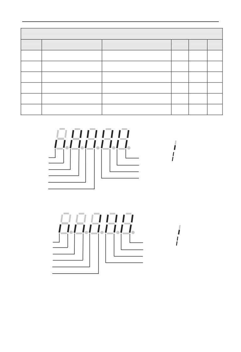
⑴corresponding relationship of input terminal status as below:
:terminal input invalid
Reserved
X1 terminal status
:terminal input valid
Reserved
X2 terminal status
X8 terminal status
X3 terminal status
X7 terminal status
X4 terminal status
X6 terminal status
X5 terminal status
⑵Corresponding relationship of standard output terminal status as below:
:terminal input invalid
Reserved
Y1 terminal status
:terminal input valid
Reserved
Y2 terminal status
Reserved
Y3 terminal status
Reserved
Y4 terminal status
Reserved
RLY terminal status
88
6 Function parameter schedule graph
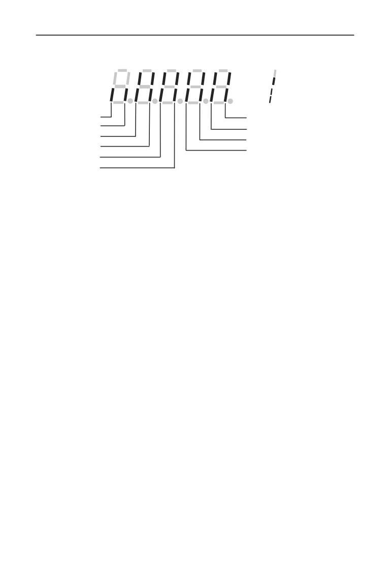
⑶Corresponding relationship of communication virtual input terminal status as below:
:terminal input invalid
:terminal input valid
Reserved
CX1 terminal status
Reserved
CX2 terminal status
CX8 terminal status
CX3 terminal status
CX7 terminal status
CX4 terminal status
CX6 terminal status
CX5 terminal status
⑷Drive status:
BIT0:1=busbar voltage setup
BIT1:1=common run command valid
BIT2:1=jog run command valid
BIT3:1=drive run period
BIT4:1=current run direction to reverse
BIT5:1=run command direction to reverse
BIT6:1=deceleration brake period
BIT7:1=motor acceleration period
BIT8:1=motor deceleration period
BIT9:1= drive alarm
BIT10:1= drive fault
BIT11:1= current limited period
BIT12:1= fault self-recovery period
BIT13:1= self-adjusting period
BIT14:1= free halt status
BIT15:1= speed tracking start
89
7 Detailed function specification
7 Detailed function specification
The parameter function code of this chapter listed content as below:
Code
Factory
Description
Setup Range/Explanation
No.
Default
7.1 System Parameter Group: F00
F00.00
Parameter group display control
Range: 0~3
0
0: Basic list mode. Display only F00, F01, F02, F03 basic control parameter
group and F26 fault record parameter group.
1: Middle list mode. Display all parameter except for extension: virtual and
reserve parameter group.
2: Senior list mode. All parameter groups can be displayed.
3: User list mode. Display parameter defined by user: and monitor
parameter: F00.00 display all the time.
F00.00 display all the time. Under intermediate menu mode:
irrelevant parameter group can be covered according to different
Note
control mode.
C-00 display parameter
F00.01
Range: 0~65
51
selection when operation
C-01 display parameter
F00.02
Range: 0~65
2
selection when operation
C-02 display parameter
F00.03
Range: 0~65
4
selection when operation
C-03 display parameter
F00.04
Range: 0~65
5
selection when operation
C-04 display parameter
F00.05
Range: 0~65
6
selection when operation
C-05 display parameter
F00.06
Range: 0~65
9
selection when operation
The above parameter display when inverter run by C-00~C-05 parameter groups,
pressing
to switch between these parameters.
Pressing
and then return to C-00 parameter monitor.
For example: pressing
parameter switch from C-00 to C-01: continuous
pressing the same button: parameter switch from C-01 to C-02: then pressing
return to C-00 parameter monitor.
90
7 Detailed function specification
0: Main setup frequency (0.01Hz)
1: Auxiliary setup frequency (0.01Hz)
2: Setup frequency (0.01Hz)
3: Output frequency (0.01Hz)
4: Output current(0.1A)(display 0.01A below 11KW)
5: Output voltage (1V)
6: DC busbar voltage (0.1V)
7: Motor speed (1 circle/min)
8: Motor line velocity (1 circle/min)
9: Inverter temperature (1℃)
10: Run time already this time (0.1min)
11: Current accumulate run time (1h)
12: Current accumulate power-on time (1h)
13:Inverter status (displays the working state of inverter, show it with
decimalism, after change it into binary, the definition is on the parameter
details.)
14: Input terminal status
15: Output terminal status
16: Extension output terminal status
17: Extension input terminal status
18: Communication virtual input terminal status
19: Internal virtual input node status
20: Analog input AI1 (before checkout)(0.01V / 0.01mA)
21: Analog input AI2 (before checkout)(0.01V / 0.01mA)
22: Extension analog input EAI1 (before checkout)(0.01V / 0.01mA)
23: Extension analog input EAI2 (before checkout)(0.01V / 0.01mA)
24: Analog AO1 output (after correction) (0.01V /0.01mA)
25: Analog AO2 output(after correction
(0.01V or 0.01mA)
26: Extension analog EAO1 output (0.01V /0.01mA)
27: Extension analog EAO2 output (0.01V /0.01mA)
28: External pulse input frequency (1Hz)
29: Reserved
30: Process PID provide (0.01V)
31: Process PID feedback (0.01V)
32: Process PID deviation (0.01V)
33: Process PID output (0.01Hz)
34: Simple PLC current segment No.
35: External multi-speed current segment No.
91
7 Detailed function specification
36: Constant pressure water supply provide pressure (0.001Mpa)
37: Constant pressure water supply feedback pressure (0.001Mpa)
38: Constant pressure water supplies relay status
39: Current length (1M)
40: Accumulate length (1M)
41: Current internal count value
42: Current internal time value (0.1s)
43: Run command setup channel (0: keyboard 1: terminal
2: communication)
44: Main frequency provide channel
45: Auxiliary frequency provide channel
46: Rated current (0.1A)
47: Rated voltage (1V)
48: Rated power (0.1KW)
49, 50: Reserved
51: The frequency after deceleration(0.01Hz)
52: Motor rotator frequency(0.01Hz)(the frequency estimate on the
open-loop ,actual measurement for close-loop)
53 :Present provide torque(relative to rated torque, it has direction)
54: Present output torque(relative to rated torque, it has direction)
55: Present torque current (0.1A)
56: The present flux current
(0.1A)
57~65: Reserved
C-00 display parameter
F00.07
Range: 0~65
2
selection when stop
C-01 display parameter
F00.08
Range: 0~65
6
selection when stop
C-02 display parameter
F00.09
Range: 0~65
48
selection when stop
C-03 display parameter
F00.10
Range: 0~65
14
selection when stop
C-04 display parameter
F00.11
Range: 0~65
20
selection when stop
C-05 display parameter
F00.12
Range: 0~65
9
selection when stop
The above parameter display when inverter stop by C-00~C-05 parameter group,
pressing
to switch between these parameters. Pressing
and then
92
7 Detailed function specification
return to C-00 parameter monitor. For example: pressing
parameter switch
from C-00 to C-01, continuous pressing the same button: parameter switch from
C-01 to C-02: then pressing
return to C-00 parameter monitor. Monitor
contents various as different monitor parameter: refer to parameter F00.01.
Monitor parameter group C-00~C-05 have run and stop modes.
For example C-00 display different physical value under run and
Note
stop two modes.
Power-on fault monitor
F00.13
Range: 0~5
0
parameter selection
When the parameter power on first time: C monitor parameter group display
under drive run or stop status, For example F00.13=1, power on or stop to monitor,
display parameter setup by C-01;when F00.02=3, F00.08=6, power on, inverter
stops, busbar voltage display; inverter runs, output frequency and keypad display.
Pressing
monitor C-00 for the setting motor value.
Range: units digit: 0~2
Parameter operation
F00.14
tens digit: 0~5
000
control
hundreds digit: 0~4
Units digit: To define which parameters will be allowed to modify.
0: All parameters are allowed to modification.
1: Excerpt this parameter, the other parameter is not allowed to
modification.
2: Except F01.01, F01.04 and this parameter, the others parameter are
not allowed to modification.
Tens digit: To define which parameters will be resumed factory default value
0: No action.
1: All parameters return to default.(not include fault record parameter
group(F26 group) parameter).
2: Except for motor parameter: all parameters return to default. (not
include F15 and F26 group parameter).
3: Extension parameter return to default.(only F21~F24 group parameter
return to default).
4: Virtual parameter return to default.(only F20 group parameter return to
default).
5: Fault record return to default. (Only fault record parameter group (F26
group) restores factory default).
Hundreds digit: Locked key that definite the keypad when locking function is
valid.
0: All locked.
93
7 Detailed function specification
1: Except
button: the others locked.
2: Except
,
button: the others locked
3: Except
,
button: the others locked
4: Except
,
button: the others locked
1. In factory status, the unit of this function code parameter is 0,
and it is default and allowed to change all the other function code
parameters: when user finish: and want to change the function
code setup: this function code parameter should set up 0 first.
When all changes finish and need to do parameter protect: this
function code setup into the IP grade you need.
Note
2. The decade recovers to 0 automatically after record remove or
factory default operation.
3. When the third of parameter F00.14 finish setup:
button
pressing lasting for
2 seconds to lock keyboard and relevant
keyboard key: when need to unlock the keyboard: press the
button for 2 seconds.
Range: units digit: 0,1
tens digit: 0~9
F00.15
Button function selection
0001
hundreds digit: 0,1
thousands digit: 0,1
Units digit: panel
button selection
0: Reversal command action button
1: Jog action button
Tens digit: multi-function
button function selection
0: Invalid.
1: Jog run. Multi-function button as jog run button: run direction decided by
unit bit of F01.16. After setting
function, the jog run function on the
keypad is invalid.
2: For/rev switching. Press this button to change the run direction when run:
then press the same button change to another direction. This function key is not
used as start key, only for signal switch
3: Free stop. Setup free stop function and stop mode F02.11 the same
function with 1 Jog run.
4: Switching to run command provide mode as the setup order of
F00.16.
94
7 Detailed function specification
5: For/rev torque switching. After this function is valid, it can realize the
direction switching after torque model.
6~9: Reserved
Hundredth: terminal run command control
0: keypad
is invalid.
1: keypad
is valid.
Thousandth: communication run command control
0: keypad
is invalid.
1: keypad
is valid.
Multi-function key run command
F00.16
Range: 0~3
0
channel switching order selection
0: Keyboard controlĺterminal controlĺcommunication control
1: Keyboard controlĸĺterminal control
2: Keyboard controlĸĺcommunication control
3: Terminal controlĸĺcommunication control
These parameters cooperate with multi-function key to run command channel
switching function: with special switch to command channel switching order.
1.Command channel priority terminal switch to(terminal function
code 49,50,51)ĺterminal run command channel selection(terminal
function code 52,53)ĺmulti-function key switchĺF01.15,when
switching to terminal control, be sure the terminal command
invalid. Terminal switch to and terminal run command channel
Note
selection refer to F08 group parameter about the detailed
description of terminal function.
2. We suggest alter the mode at the stop state.
Motor speed display
F00.17
Range: 0.1~999.9%
100.0%
coefficient
This function code is used to check speed scale display error, there is no effect to
motor actual speed.
Line velocity display
F00.18
Range: 0.1~999.9%
1.0%
coefficient
This function code is used to check speed scale display error, there is no effect to
motor actual speed.
F00.19
Extended Port parts set
Range: 0~10
0
0: Expansion card invalid
95
7 Detailed function specification
1: Reserved
2: Multi pump water supply card
3: Incremental PG encoder
4~10: Reserved
This function is for extended port expansion card parameter, after setting
expansion card, F00.19 will choose the expansion card number accordingly, then
we can use the expansion card normally. For example, when Extended Port add
PG expansion card, F00.19 should be set to 3.
Range: units digit: 0,1
Analog input terminal
tens digit: 0,1
F00.20
0000
configuration
hundreds digit: 0~2
thousands digit: 0~2
This parameter can configurate analog input AI1, AI2, EAI1, EAI2 to be current
input type or voltage input type.
Units digit: AI1 configuration
0:0~10V input
1:4~20mA input
Tens digit: AI2 configuration
0:-10~10V input
1:4~20mA input
Hundreds digit: EAI1 configuration
0:0~10V input
1:-10~10V input
2:4~20mA input
Thousands digit: EAI2 configuration
0:0~10V input
1:-10~10V input
2:4~20mA input
Dial switching(SW1,SW2)under the left corner of CPU to the
corresponding position: when AI1,AI2 configuration.
Note
Range: units digit: 0,1
Analog output terminal
tens digit: 0,1
F00.21
0000
configuration
hundreds digit: 0,1
thousands digit: 0,1
This parameter can configurate AO1, AO2, EAO1, EAO2 analog signal output to
be voltage type or current type.
Units digit: AO1 configuration
0:0~10V output
96
7 Detailed function specification
1:4~20mA output
Tens digit: AO2 configuration
0:0~10V output
1:4~20mA output
Hundreds digit: EAO1 configuration
0:0~10V output
1:4~20mA output
Thousands digit: EAO2 configuration
0:0~10V output
1:4~20mA output
Dial switching(SW1,SW2)under the left corner of CPU to the
corresponding position: when AI1,AI2 configuration.
Note
Range: units digit: Reserved
Y output terminal
tens digit: Reserved
F00.22
0000
configuration
hundreds digit: Reserved
thousands digit: 0,1
Units digit ~ hundreds digit: Reserved
Thousands digit: Y4 output configuration
0: Open collector output
1: DO output
The thousands digit decide the Y4 output terminal type, when 0 means open
collector output, when 1 means high speed pulse DO output. .
F00.23
G/P type setup
Range: 0, 1
0
0:G type. Adapt to constant torque load type.
1:P type. Adapt to fan & pump load type.
EN500/EN600 integrates G/P type design in full power range. F15 group motor
relative parameter will change automatically according to the G or P type.
P type machine only can support V/F control .
Note
F00.24
Motor control model
Range: 0~2
0
0: V/F control
If we need to start the fan and water pump application , or the inverter should
drive one more AC motors, please choose the V/F control mode, when drive parts
of the synchronous machines, we also can choose V/F control.
1: Speedless Vector Control 1 (Comparing with the speed vector control 2,
the mode is more suitable to control the induction motor below
160KW,
97
7 Detailed function specification
supporting the speed and torque control)
Speedless sensor vector control run mode, mainly used to velocity control, torque
control in the application site which require high control performance. To get
better control performance, we need to set up motor parameter group F15
according to the motor nameplate details, and doing the self-learning to motor
parameter. One VFD can only drive one motor in vector control mode, and VFD
power need match up with motor, normally one class less or more of the VFD
power than motor is allowed.
2: with speed sensor vector control (support the speed and torque control)
When choose the closed-loop vector control mode, the AC motor should be
installed with an encoder, and the inverter should be installed with the same type
of the encoder. It can be used on the high-accuracy speed control & torque control
application. One inverter only can drive one AC motor, like Paper-make machine,
cranes, and elevator.
When using the closed-loop control, including setting motor parameter (F15
group), we should also set the encoder parameter group (F16),and the Extended
Port (F00.19) parameter.
F00.25
Monitor parameter 2 selection
Range : 0~65
2
When user choose EN-LED2 keypad , under monitoring mode we can use F00.25
parameter to modify monitoring content of keypad digital display (LED2).
When user choose EN-LCD1 or EN-LCD2 keypad, under monitoring mode we
can use F00.25 parameter to change monitoring content of below LED.
For monitoring content of F00.25 parameter, please refer to description of F00.01
F00.26
Busbar voltage adjustment
Range : 0.900~1.100
1.000
We can use this parameter to adjust the busbar voltage; to make the inverter bus
voltage is accordingly to the exact figures.
Parameter copying and
Range: units digit: 0~2
F00.27
00
language selection
tens digit: 0~2
Units digit: language selection. (Only valid for LCD keypad)
0: Chinese
1: English
2: Reserve
Tens digit: parameter upload and download
(valid for LCD and digital
potentiometer keypad)
0: No action
1: Parameter upload
2: Parameter download
98
7 Detailed function specification
7.2 Basic Run Function Parameter Group:F01
Main frequency input
F01.00
Range: 0~14
0
channel selection
Total 15 types input channel for selection to chose inverter input channel of the
main provide frequency,among 11~14 are reserve channel,currently there is no
corresponding function.
0:Operation keyboard digital setup. When main frequency setup initial
value to F01.01: modify F01.01 parameter to change main setting frequency with
operation keyboard: or with
,
button to modify the value of F01.01
1:AI1 analog setup. Main frequency setup confirmed by AI1 analog
voltage/ current, input range:
0~10V (AI1 jumper wire selection V side)or
4~20mA(AI1 jumper wire selection A side).
2:AI2 analog setup. Main frequency setup confirmed by AI2 analog
voltage/current, input range:
-10~10V (AI2 jumper wire selection V side)or
4~20mA(AI2 jumper wire selection A side).
3:Terminal UP/DOWN adjusting setup. When main frequency initial
value is parameter F01.01, through terminal UP/DOWN function to adjust the
main setting frequency. Terminal function setup into
16(frequency increase
progressively (UP))or 17(frequency decrease progressively control(DOWN)).
4:Communication provide. Main frequency provide by selection
communication mode.
5:EAI1 analog setup. When extension analog input EAI1 is valid,main
frequency confirmed by EAI1 analog voltage/current,input range:-10~10V(EAI1
jumper wire selection V side)or 4~ 20mA(EAI1 jumper wire selection Aside).
Relevant extension card selection needed to use this setup function.
6:EAI2 analog setup. when extension analog input EAI2 valid,main
frequency setup by EAI2 analog voltage / current,input range:-10~10V(EAI2
jumper wire selection V side) or 4~ 20mA(EAI2 jumper wire selection A side).
Relevant extension card selection needed to use this setup function.
7:High speed pulse setup. main frequency setup by frequency signal of
terminal pulse(only X8 input),input pulse specification:voltage range 15~30V;
frequency range 0.00~50.00KHz.
8:Terminal pulse setup. main frequency setup by pulse width signal of
terminal pulse(only X8 input),input pulse specification:voltage range 15~30V;
pulse width range 0.1~999.9ms.
9:Terminal encoder setup.main frequency setup by terminal encoder
pulse(only combination input by X1 and X2) and frequency velocity set by
parameter F08.30.
99
7 Detailed function specification
10~14: Reserved
Analog provide is positive and negative polarity control,its prior to
command direction control: when main frequency provide is
AI2,EAI1,EAI2: and setup provide to be -10~10V,run direction
confirmed by analog provide signal polarity completely,when PID
Note
run is valid, run direction confirmed by PID error polarity and
parameter F11.21 completely.
Excerpt terminal encoder provide (F01.00=9), main and auxiliary
provide channel cannot be set into the same frequency source: if
!
they are the same: then panel would be light (ALM) and display
A-51.
Main frequency digital
Range:0.00Hz~upper
F01.01
50.00Hz
setup
limit frequency
When F01.00=0,3 or 4,F01.01 is the initial value of main frequency.
Main frequency digital
F01.02
Range: 00~11
00
control
Units digit: power down reserve setup
0:Main frequency power down reserve. When main frequency channel
provide is valid, power down in run status, current main frequency of run
frequency is recorded in parameter F01.01.
1: Main frequency power down no reserve.
Tens digit: halt reserve setup
0:Halt main frequency hold. When main frequency channel provide is
valid, current run frequency only recorded after halt.
1:Halt main frequency recovery F01.01. main setting frequency recorded
in software is recovery to value of parameter F01.01 after halt.
Only when parameter F01.00=0, 3, 4, it can be valid, after
power-fail or Stop storage function both are valid,stop the machine
Note
first, it also can serve.
Auxiliary frequency input
F01.03
Range : 0~20
20
channel select
VFD auxiliary provides frequency input channel has
21 input channels for
selection, for them
11~20 are Reserved channels, and currently there is no
relevant function:
100
7 Detailed function specification
0:Keyboard operation digital setup. When auxiliary frequency setup
initial value is parameter F01.04, modify parameter F01.04 to change auxiliary
setting frequency: or with
,
button modify the value of parameter
F01.04
1:AI1 analog setup. Auxiliary frequency setup confirmed by AI1 analog
voltage
/current, input range:
0~10V (AI1 jumper wire selection V side)or
4~20mA(AI1 jumper wire A side).
2:AI2 analog setup. Auxiliary frequency setup confirmed by AI2 analog
voltage/current, input range:
-10~10V (AI2 jumper wire selection V side) or
4~20mA (AI2 jumper wire selection A side).
3:Terminal UP/DOWN adjusting setup. Auxiliary frequency initial value
is parameter F01.04, through terminal UP/DOWN function to adjust auxiliary
setting frequency.
4:communication setting. The initial value of auxiliary frequency is for
F01.04, it will determine by F05.00 of the communication setting.
5:EAI1 analog setup. When extension analog input EAI1 is valid, auxiliary
frequency setup confirmed by EAI1 analog voltage/current, input range: -10~10V
(EAI1 jumper wire selection V side)or 4~20mA(EAI1 jumper wire selection A
side).
6:EAI2 analog setup. When extension analog input EAI2 is valid, auxiliary
frequency setup confirmed by EAI2 analog voltage/current, input range: -10~10V
(EAI2 jumper wire selection V side) or 4~20mA (EAI2 jumper wire selection A
side).
7:High speed pulse setup. Auxiliary frequency setup by frequency signal of
terminal pulse (only X8 input), input pulse specification: voltage range 5~30V;
frequency range 0.00~50.00 KHz.
8:Terminal pulse width setup. Auxiliary frequency setup by pulse width
signal of terminal pulse (only X8 input), input pulse specification: voltage range
15~30V; pulse width range 0.1~999.9ms.
9:Terminal encoder provide. Auxiliary frequency setup by terminal
encoder pulse (only X3 or X4 input), 0.01Hz is a fixed adjusting precision.
10~20: Reserved.
Analog provide is positive and negative polarity control,its prior to
command direction control: when auxiliary frequency provide is
Note
AI2,EAI1,EAI2 ,and setup provide is to be -10~10V,run direction
confirmed by analog provide signal polarity completely.
101
7 Detailed function specification
Except terminal encoder provide( F01.03=9),main and auxiliary
provide channel cannot setup to the same frequency source,when
!
they are the same,then panel light(ALM),and A-51 display.
Auxiliary frequency digital
Range:0.00Hz~upper
F01.04
0.00Hz
setup
limit frequency
When F01.03=0, 3 or 4, F01.04 is the initial frequency value of auxiliary
frequency.
Auxiliary frequency digital
F01.05
Range: 00~11
11
control
Units digit: power down reserve setup
0:Auxiliary frequency power down reserve. When auxiliary frequency
channel provide is valid and power down at run mode, the current auxiliary setting
frequency reserve in parameter F01.04.
1:Auxiliary frequency power down no reserve.
tens digit: halt reserve setup
0:Halt auxiliary frequency hold. When auxiliary frequency channel
provide is valid, recording current run frequency only after halt.
1:Halt auxiliary frequency recovery parameter F01.04 .auxiliary setting
frequency in software recording is recovered the value of parameter F01.04 after
halt.
Only when F01.03=0,3,4 is valid.
Note
Main and auxiliary provide
F01.06
Range: 0~7
0
calculating setup
This parameter is to select frequency provide channel: and through the complex of
main frequency source and auxiliary frequency source to achieve frequency
provide.
0:Main frequency. Complex frequency of current is main frequency.
1: Auxiliary frequency. Complex frequency of current is auxiliary
frequency.
2: Plus(polarity oppose of complex and main frequency,complex frequency
is zero).
3:Minus(polarity oppose of complex and auxiliary frequency,complex
frequency is zero).
4:Multiplication(polarity opposed of main and auxiliary frequency:
102
7 Detailed function specification
complex frequency is zero).
5:Max(the max frequency of main and auxiliary absolute value).
6:Min(the min frequency of main and auxiliary absolute value).
7:Selection no-zero value(auxiliary is not negative,main frequency
prior;auxiliary is negative,complex frequency is zero)
1.The initial polarity of main and auxiliary frequency cannot
change after main and auxiliary operation.
2.When main and auxiliary frequency channel are complex
value,and both setup into power down reserve: parameter F01.01
Note
and F01.04 reserve separately the changed part of main frequency
and auxiliary frequency in the complex frequency when power
down.
Auxiliary frequency
F01.07
Range : 0.00~10.00
1.00
provide coefficient
Parameter F01.07 can adjust auxiliary provide frequency gain.
Coefficient after complex of
F01.08
Range: 0.00~10.00
1.00
main and auxiliary frequency
This parameter is to setup frequency flexibly and calculates the gain of complex
setting frequency by main and auxiliary frequency.
Auxiliary frequency range
F01.09
Range: 0, 1
0
selection
0:Relative high limit frequency. Auxiliary frequency setup range:
0.00Hz~high limit frequency×F01.10.
1:Relative main frequency. Auxiliary frequency setup range: 0.00Hz~main
frequency×F01.10.
Auxiliary frequency source
F01.10
Range: 0.00~1.00
1.00
scope
This parameter cooperate with F01.09 define the scope of auxiliary provide
frequency. Auxiliary provide frequency high limit value is restrained by the
frequency selected by parameter F01.09 through parameter F01.10 gain
calculation.
Range: lower limit
F01.11
Upper limit frequency
50.00Hz
frequency~600.00Hz
This parameter’s max setting frequency of all run modes should be modification
carefully according to the motor nameplate details.
Range: 0.00Hz~upper limit
F01.12
Low limit frequency
0.40Hz
frequency
Low limit frequency
F01.13
Range : 0~3
2
run mode
103
7 Detailed function specification
Sleep run hysteresis
Range: 0.01Hz~upper limit
F01.14
0.01Hz
frequency
frequency
0: As low limit frequency run.
1: As setting frequency run.
2: As zero frequency run.
3: Sleep: PWM clocked at sleep mode.
When actual setting frequency lower than low limit frequency, low limit frequency
run mode selection 0,then drive run at low limit frequency; low limit frequency run
mode selection 1,drive continuously run according to setting frequency; low limit
frequency run mode selection 2,drive continuously low output frequency and run at
zero frequency; low limit frequency run mode selection 3,immediately clock the
output and display frequency decline slowly to zero, when provide value over low
limit frequency, drive restart to accelerate run from 0Hz to provide value after
through F01.14 stagnant loop.
When F01.13=3: this parameter can finish sleep function to achieve
energy saving run and avoid drive to start frequently at threshold
Note
value through width of return difference.
F01.15
Run command channel selection
Range: 0~2
0
0: Operation keyboard run control. Start and stop with
1: Terminal run command control. Terminal X1 is forward (FWD),X2 is
reverse(REV)during the function code X1~X8 setup. Other terminal can also be
regarded as for/rev input terminal.
2: Communication runs command control. Start and stop with
communication mode.
1.Drive can change run command channel through switch of
multi-function key,terminal command channel in halt and
run,carefully modify command channel after confirm in site the
permission to run command channel modification. After the
command channel modification: keyboard
button setup valid
!
or not by parameter F00.15.
2.After run command channel modification,frequency channel can
be defined by parameter F18.00,F18.01,F18.02 .or defined by
parameter F01.00,F01.03,F01.06 and multi-function terminal.
104
7 Detailed function specification
Range: units digit: 0,1
F01.16
Run direction setup
00
tens digit: 0~2
Units digit: Keyboard command for/rev setup (only valid to keyboard inching
command)
0: Forward.
1: Reverse.
Tens digit: for/rev forbid
(suitable for all command channel, not include
inching function)
0: For/rev available.
1: Reverse not available (imposing on reverse, stop as the halt mode).
2: Forward not available (imposing on forward, stop as the halt mode).
F01.17
Acceleration time 1
Range: 1~60000
Depend on type
F01.18
Deceleration time 1
Range:1~60000
Depend on type
Acceleration time is interval accelerate from zero frequency to high limit
frequency, deceleration time is the interval decelerate from high limit frequency to
zero frequency. The unit defined by F01.19. Example: F01.17=100, F01.19=1,
acceleration time 1 is 10.0 seconds.
1.EN500/EN600 series drive defines
15 acceleration and
deceleration time, only acceleration and deceleration time
1
defined here, acceleration and deceleration
2~15 defined in
Note
parameter F04.16~F04.43.
2.acceleration and deceleration
1~15 select time unit through
parameter F1.19,factory default unit is 0.1 second.
F01.19
Accelerate/decelerate time unit
Range: 0~2
1
This function can define acceleration and deceleration time unit.
0:0.01s
1:0.1s
2:1s
1.The function is valid to all acceleration and deceleration excerpt
for inching run.
Note
2.Advise to select 0.1s as the time unit.
F01.20
Accelerate/decelerate mode selection
Range: 0, 1
0
0:Line acc/dece mode. Output frequency raises or decline as the constant
slope, as fig.7-1.
105
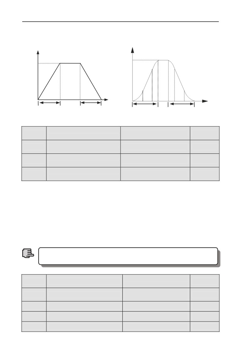
7 Detailed function specification
1: S curve acc/dece mode. Output frequency raise or decline as the S curve:
as fig.7-2.
Freq.
Freq.
50.00Hz
50.00Hz
①
③
②
②
time
③
① time
t1
t2
t1
t2
Fig. 7-1 Line acc/dece
Fig. 7-2 S curve acc/dece
S curve acceleration
F01.21
Range: 10.0%~50.0%
20.0%
initiation segment time
S curve acceleration up
F01.22
Range: 10.0%~70.0%
60.0%
segment time
S curve deceleration
F01.23
Range: 10.0%~50.0%
20.0%
initiation segment time
S curve deceleration up
F01.24
Range: 10.0%~70.0%
60.0%
segment time
F01.21~F01.24 select S curve acceleration and deceleration mode(F01.20=
1)valid only under acceleration and deceleration, and F01.21+F01.2290%
,
F01.23+F01.2490%.
S curve starts interval time as fig.7-2③, output frequency changed slope increase
slowly from zero.
S curve up interval time as fig.7-2②, output frequency changed slope is constant.
S curve ends interval time as fig.7-2①, output frequency changed slope decrease
slowly to zero.
S curve acc/dece mode is suitable for the start and stop of elevator,
conveyor belt, transport and transfer load so on.
Note
Range:0.00Hz~upper
F01.25
Keyboard jog run frequency
5.00Hz
limit frequency
Range:0.00Hz~upper
F01.26
Terminal jog run frequency
5.00Hz
limit frequency
F01.27
Jog interval time
Range: 0.0~100.0s
0.0s
F01.28
Jog acceleration time
Range: 0.0~6000.0s
20.0s
F01.29
Jog deceleration time
Range: 0.0~6000.0s
20.0s
106
7 Detailed function specification
F01.25, F1.26 defines keyboard jog and terminal jog run frequency, when jog run:
accelerate as the zero frequency, and not effect by the start mode defined by
parameter F02.00. When jog command revocation, stop as setting halt mode,
when input another command during the deceleration, accelerate or decelerate
according to the current frequency.
F1.27 defies valid command interval time at continuously jog. When jog
command invalid, the time restart jog command is short than jog interval time, jog
command ignore here.
F1.28, F1.29 defines jog run acceleration and deceleration time, fixed unit is 1s.
107
7 Detailed function specification
7.3 Start, stop, forward/reverse, brake function parameter group:
F02
F02.00
Start running mode
Range: 0~2
0
0: Start from starting frequency. After receiving start command by setting
F02.01 delay time, the inverter starts after setting F02.02 starting frequency and
F02.03 starting frequency duration.
1: First brake, and then start from starting frequency. First brake the
current from DC and then from time (F02.04, F02.05), and then start after setting
starting frequency and starting frequency duration set by F02.03.
2: Speed tracking start. This mode can be supported by the entire motor
control model at the present.
1.Start-up mode 0: It is suggested to use Start-up mode 0 for general
purpose applications and for general drive synchronous motor.
2. Start-up mode 1: Suitable for small inertia load, for example,
forward and reverse occurs when the motor is not driven.
3. Start-up mode 2: Suitable for the starting of large inertia load
before stopping stably. Generally this mode is used when restarting
after power failure, fault self-recovery and other functions. The
Note
following points need to be noticed when this Start-up mode is used:
3.1 When the inverter stops freely, restart the inverter after a few
seconds. If over-current fault occurs when starting, please extend the
F02.08 time.
3.2 Do not modify the set frequency when the inverter starts in slow
down process.
4 .When torque model is valid, we suggest use the start mode 2.
F02.01
Starting delay time
Range: 0.0~60.0s
0.0s
Starting delay time refers to the waiting time before the inverter is started after
receiving running command.
F02.02
Starting frequency
Range: 0.0~10.00Hz
0.00Hz
Starting frequency duration
F02.03
Range: 0.0~60.0s
0.0s
time
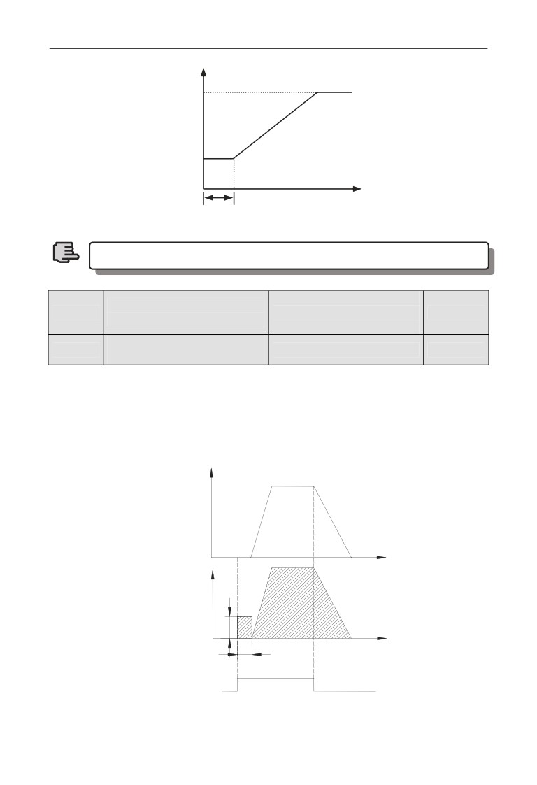
Starting frequency refers to the initial frequency when the inverter is started, as
shown in Fig. 7-3 fs; starting frequency holding time refers to consecutive running
time during which the inverter runs at the starting frequency, as shown in Fig. 7-3
t1.
108
7 Detailed function specification
fmax
fs
Start
time
Freq.
Starting
t1
time
Fig. 7-3 Starting frequency and starting time
Starting frequency is not limited by lower limit frequency.
Note
Range: 0.0 ~ 100.0%
DC braking current when
F02.04
(G type inverter rated
30.0%
starting
current)
DC braking time when
F02.05
Range: 0.0~30.0s
0.0s
starting
When F02.00=1, F02.04, F02.05 valid, and stop mode is deceleration stop, as shown
in Fig. 7-4.
The setting of starting DC braking current is with respect to the percentage of
inverter rated output current. When starting DC braking time is 0.0 second, no DC
braking process.
Output Freq.
DC brake
Time
Output volt
quantity
(Valid value)
Time
DC brake time
Running command
Fig. 7-4 Starting mode 1 description
109
7 Detailed function specification
Speed track starting
F02.06
Range: 0~2
2
frequency selection
0: Current setting frequency.
1: Running frequency before power down.
2: Speed track auxiliary starting frequency.
Select frequency closed to the current running frequency of the motor so as to
track the current running revolving speed of the motor. For example, when current
running frequency is closed to current setting frequency, then select 0 and start to
search from current setting frequency.
Speed track auxiliary
Range:0.00Hz~upper
F02.07
10.00Hz
starting frequency
limit frequency
This parameter defines when 2 is selected in F02.06 parameter, the starting
searching frequency when revolving track is started.
Speed track starting
F02.08
Range: 0.00~10.00s
0.10s
waiting time
When 2 is selected in F02.00, if the inverter checks that the running command is
valid, the revolving speed is searched after the time defined by F2.08.
Speed track current control
F02.09
Range: 1~20
2
coefficient
This parameter define the speed search process tracking current, the bigger of the
value , the faster it can track.
Speed track searching
F02.10
Range: 0.1~30.0
4.00
speed time
This parameter can be modified to improve speed track time.
On SVC control, the minimum unit of speed tracking for search speed time
is 0.1s;
On V/F control, the minimum unit of speed tracking for search speed time is
1s;
1. F02.06~F02.09 parameter only can be started on the speed
variator, the start is valid.
Note
2.F02.10 parameter can be used for both V/F model and SVC
model .
F02.11
Stop mode
Range: 0~2
0
0: Deceleration stop. After receiving stop command, the inverter reduces
output frequency gradually according to the set deceleration time, the inverter
stops when frequency is 0.
1: Free stop. After receiving stop command, the inverter stops output
110
7 Detailed function specification
immediately, and the load stops freely according to mechanical inertia.
2: Deceleration + DC braking stop. After receiving stop command, the
inverter reduces output frequency gradually according to the set deceleration time.
When reaching F02.14 starting frequency of stop braking, After F02.15 defines
DC braking waiting time, the inverter starts DC braking, as shown in Fig. 7-5.
Deceleration stop holding
Range: 0.00Hz~upper
F02.12
0.00Hz
frequency
limiting frequency
Deceleration stop holding
F02.13
Range: 0.00~10.00s
0.00s
time
The parameters F02.12 and F02.13 define inverter’s deceleration stop holding
function. When the frequency reaches set value of F02.12 in deceleration, it stops
deceleration, and maintains the set time of F02.13, and enters deceleration state.
This parameter is only valid for stop mode 0.
Stop DC braking starting
F02.14
Range: 0.00~15.00Hz
0.00Hz
frequency
Sop DC braking waiting
F02.15
Range:0.00~30.00s
0.00s
time
Range: 0.0~100.0%
F02.16
Stop DC braking current
(G type machine rated
0.0%
current)
F02.17
Stop DC braking time
Range: 0.0~30.0s
0.0s
Range: 0.0~100.0%
Stop auxiliary braking
F02.18
(G type machine rated
0.0%
current
current)
F02.19
Stop auxiliary braking time
Range: 0.0~100.0s
0.0s
F02.14 ~ F02.19 parameter defines the current and duration inputting to the motor
in the stop DC braking state. If F02.17, F02.19 or F02.14 parameter is 0.0s, then
no DC braking process.
Auxiliary DC brake means when the inverter stops DC brake is finished give the
second stage DC braking. Role in some special circumstances require rapid
braking, and stop long time in the state of DC braking, but to prevent motor heat
circumstances.
111
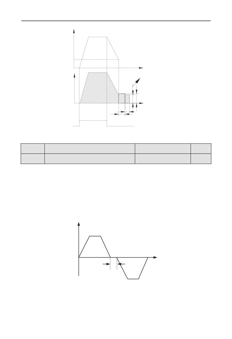
7 Detailed function specification
Output freq.
Stop brake
Starting freq.
Time
Auxiliary brake quantity
Output volt.
(Valid value)
DC brake quantity
Time
Auxiliary brake time
Stop DC brake time
Running command
Fig. 7-5 Deceleration stop + DC braking
F02.20
Forward/reverse dead zone time
Range:0.0~3600.0s
0.0s
F02.21
Forward/reverse switching mode
Range: 0, 1
0
0: Over zero switchover
1: Over starting frequency switchover
Forward/reverse dead zone time refers to the process in which the inverter
operates from forward to reverse or from reverse to forward. After output
frequency reaches the defined frequency in switchover mode, entering in to the
transition time, as shown in Fig. 7-6 t1, within transition time t1, output frequency
is 0Hz.
Output
time
t1
Fig. 7-6 Forward/reverse dead zone time
112
7 Detailed function specification
Energy consumption
F02.22
Range: 0, 1
0
braking selection
0: No energy consumption braking.
1: Energy consumption braking.
1.Please set the function parameter correctly according to the
actual use condition. Otherwise, control feature will be affected.
Before starting this function, make sure the inverter has built-in
Note
brake unit and brake resistor.
2.When the inverter is below 15KW, this parameter value is 1;
when inverter is up 15KW,this parameter value is 0.
Energy consumption
Range:115.0~145.0%
F02.23
125.0%
braking voltage
(rated busbar voltage )
Energy consumption
F02.24
Range:0.0~100.0%
100.0%
braking use rate
Energy consumption braking function is only valid for built-in brake unit. F02.23
defines energy consumption braking busbar voltage threshold value, F02.24
parameter adjusts duty ratio brake unit. The higher the brake use rate is, the
greater the brake unit duty ratio is, and the more apparent the brake effect is, but
when fluctuation of the brake process busbar voltage is more apparent, user needs
to select proper parameter based on brake resistor and brake power.
F02.25
Encryption time
Range:0~65535h
0
When F02.25>1, the encryption time is available. When the running time exceed
the time defined by F02.25, the inverter will stop and it will restart after decode.
F02.26
Reserved
113
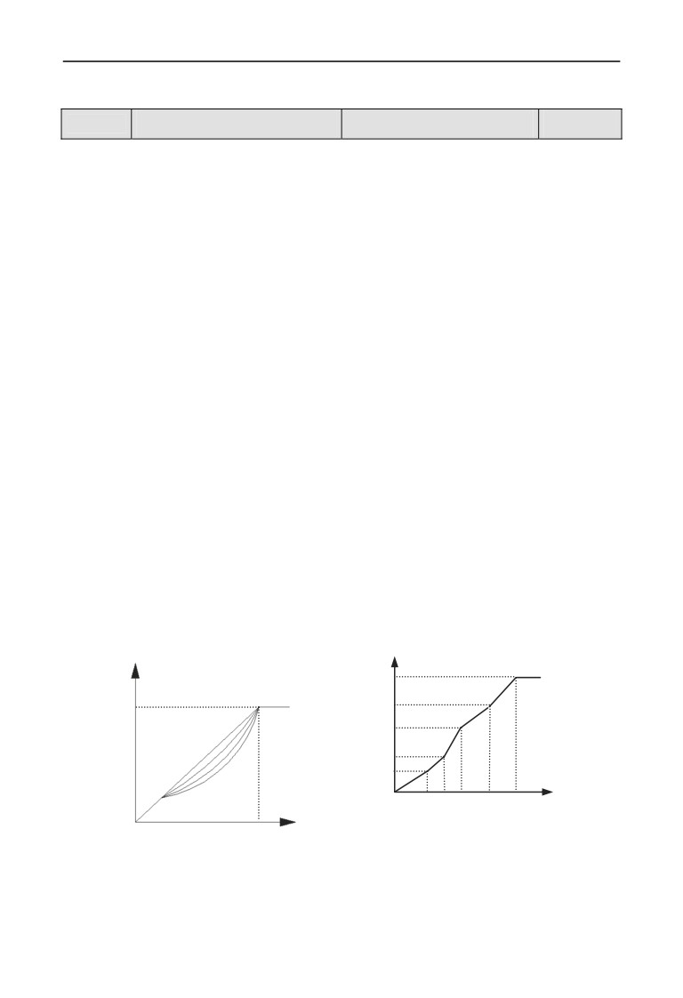
7 Detailed function specification
7.4 V/F control parameter group: F03
F03.00
V/F curve set
Range: 0~4
0
0: Constant torque curve.
1: Degression torque curve 1.
2: Degression torque curve 2.
3: Degression torque curve 3.
4: V/F curve setting (V/F frequency and voltage cannot be 0 or Max. value).
This function code defines EN600 flexible V/F setting mode to satisfy different
load characteristics. 4 kinds of fixed curves and one customized curve can be
selected according to definition of F03.00.
When F3.00=0, V/F curve is Constant torque curve feature, as shown in Fig. 7-7a
curve 0.
When F03.00=1, V/F curve is 2.0 order power degressive torque characteristic, as
shown in Fig. 7-7a curve 3.
When F03.00=2, V/F curve is 1.7 order power degressive torque characteristic, as
shown in Fig. 7-7a curve 2.
When F03.00=3, V/F curve is 1.2 order power degressive torque characteristic, as
shown in Fig. 7-7a curve 1.
User can choose 1, 2, 3 V/F curve running mode according to load characteristic
to reach better energy-saving effect when the inverter drives degressive torque
load such as blower and water pump etc.
When F03.00=4, user can set V/F curve by setting F03.04 ~ F03.11 parameter.
As shown in Fig. 7-7b, V/F curve can be defined freely by setting (V1, F1),
(V2, F2), (V3, F3), (V4, F4) to meet special load environment.
Voltage %
Output voltage
100%
Rated voltage
V3
V2
0
1
2
V1
3
V0
Freq. Hz
Output freq.
F0 F1F2
F3 Fb
0
V0~V3: The 1st-4th voltage percentage of multi section V/F
Rated freq.
F0~F3: The 1st-4th frequency points of multi section V/F
Fb: Rated frequency
Fig. 7-7 a V/F curve
b User-setting V/F curve
114