ENC EN500 / EN600 series inverter (ver. 2.0). Service manual - page 2
4 EMC(Electromagnetic Compatibility)Explanation
4.1.2 Basic countermeasure for restrain interference
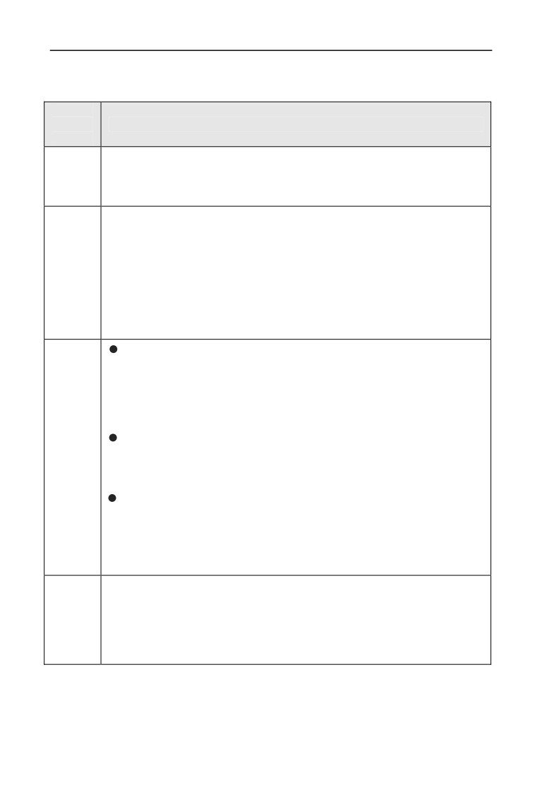
Table 4-1 interference restrain countermeasure
Noise
spread
Countermeasure of weakening effect
road
Earth grounding cable of peripheral device and inverter wiring make
up of the closed-loop and leakage current of inverter earth grounding
①
cable will make device perform wrong action. It will decrease wrong
action when device not connect to earth grounding.
When the power of peripheral device and inverter power belong to the
same power source, high harmonic gererating from inverter will
transmit the voltage and current along with the power line which will
interfere other devices within the same power source system. Take
②
some restraining measures as below:install electromagnetic noise
filter at inverter input end; use isolation transformer to isolate other
devices; connect power end of peripheral device to remote power
grid;add power ferrite filter magnetic ring to inverter R、S、T three
phase wire to restrain high harmonic current conduction
Keep other sensitive devices and signal wire installed away from
inverterr. it should use shield wire and make the shield layer single
end earth grounding. Besides keep distance from inverter and its
input & output wire as possible as. When signal wire need to
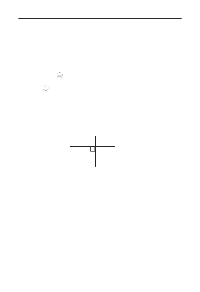
intersect with strong current cable, it should make them orthogonal
crossing not parallel.
Install high frequency noise filter (ferrite common code choke,
also called magnetic ring) at the bottom end of the inverter input &
③④⑤
output to restrain radio frequency interference of dynamic wire
effectively.
Motor cable should be placed in protective object with large
thickness, such as placed in larger thickness(over 2mm) pipeline or
buried in cemented tank. Putting dynamic wire in metal tube and
connect to earth grounding with shield wire (motor cable use 4-core
cable, one side is earthed through the inverter, the other side
connected to motor casing).
To prevent wire parallel or bundled of strong and weak current, it
should keep away from inverter assemble device, and wiring should
away from inverter R,S,T,U,V,W equipower line. Devices with
⑥⑥⑥
highfield and high magnetic field should notice the corresponding
installation position of inverter and keep distance and orthogonal
crossing.
35
4 EMC(Electromagnetic Compatibility)Explanation
4.2 Field wiring and earth grounding
⑴ inverter terminal motor connection wire (U,V,W terminal output wire)and
inverter terminal power connection wire(R,S,T terminal input wire)should keep
distance enough as possible as can.
⑵ U,V,W terminal 3 motor wires should be placed in metal tube or metal wiring
tank as possible as.
⑶ Generally control signal wire should use shield cable, when shield layer
connect to inverter
terminal, it should be the single end earth grounding which
closed to inverter side.
⑷ Inverter terminal earth grounding cable must directly connect to floor, it cannot
connect to earth grounding through other device, and the location of earth grounding
should close to inverter as possible as.
⑸ strong current cable(R,S,T,U,V,W) cannot parallel wiring closely with control
signal wire, and bundled together is prohibited. It should keep distance from over
20~60 cm(relative to strong current size). When it’s necessary to intersect, it
should be orthogonal crossing, show as Fig.4-2.
Power wire or motor cable
Control signal wire
Fig.4-2 system wiring demand
⑹earth grounding wire for strong current should separately connect to earth
grounding with control signal and sensor earth grounding wire for weak current.
⑺ Forbid to connect inverter input terminal(R,S,T) to other devices.
4.3 Leak current and countermeasure
The leak current flows through inverter input and output terminal for wire
capacitance and motor capacitance, and its size decided by the distributed
capacitance and carrier frequency. There are two kinds of leak current: leak
current to earth and wire-to-wire. Restraining methods as below:
⑴ diminish the cable length between inverter and motor.
⑵ install ferrite magnetic ring or output reactor at the inverter output terminal.
36
4 EMC(Electromagnetic Compatibility)Explanation
When reactor installed with rated voltage drop more 5% and long
wiring to U, V, W terminal , it would reduce motor’s voltage
!
apparently. When motor run at full load, it is possible to flash
motor, and it should be used by derating or boosting input and
output voltage.
⑶ as carrier frequency low, the motor noise would increase accordingly.
4.4 Installation demand for electromagnetic on-off electronic device
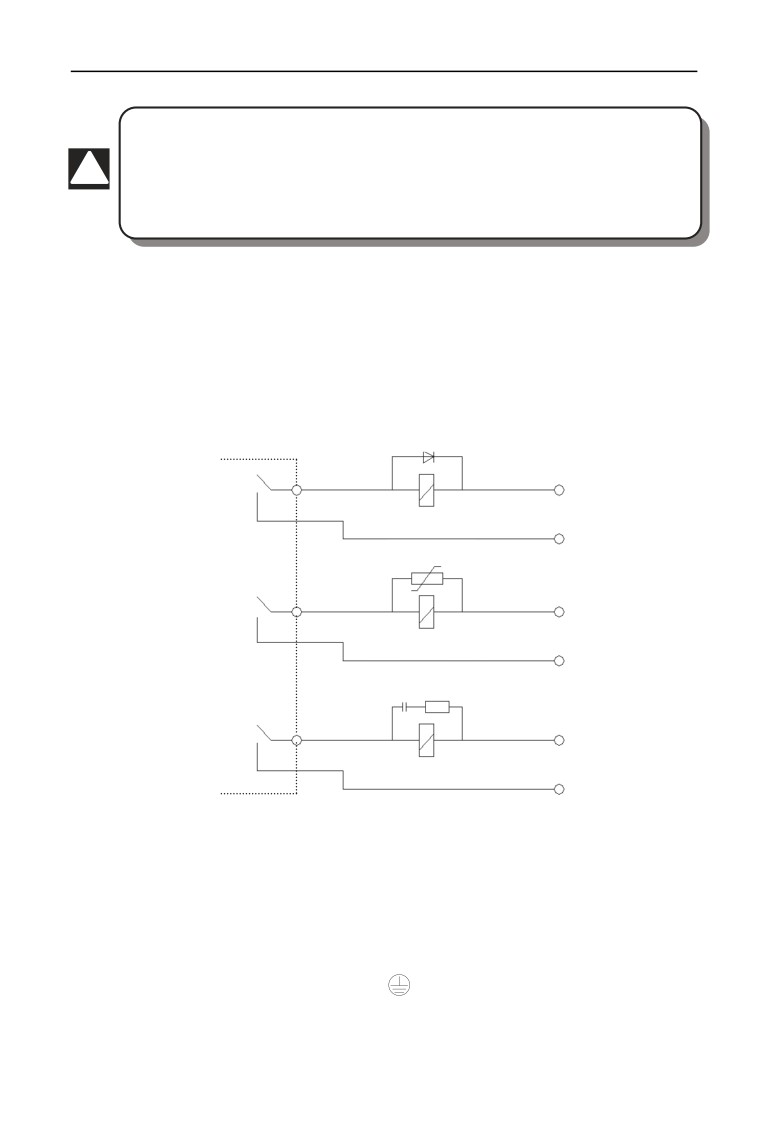
It should pay attention that surge absorber must be installed when electromagnetic
on-off electronic device like relay, electromagnetic contactor and electromagnetic
iron generating noise easily and largely installed near to inverter or in the same
control cabinet, show as Fig. 4-3.
diode
+
24VDC
_
varistor
Inverter or
other devices
~
220VAC
~
RC-filter
~
220VAC
~
Fig.4-3 install demand for electromagnetic on-off device
4.5 Noise filter installation instructions
⑴ To use strictly as per the rated value;filter metal casing grounding must
connect reliably to assemble cabinet metal grounding in large scale and it required
good conductive continuity. Otherwise, it may cause electric shock and influence
the EMC effect seriously.
⑵ Filter grounding terminal and inverter
terminal must connect to the same
common earth grounding, otherwise it will influence the EMC effect seriously.
⑶ Filter installed as close as possible to inverter power input terminal.
37
5 Run and operation explanation for inverter
5 Run and operation explanation for inverter
5.1 Run of inverter
5.1.1 Running order channels
There are 3 kinds of order channel for controlling run action of the inverter such as
run, stop, jog etc.
0:keypad
Control by key
,
,
on keypad (factory default).
1:Control terminal
Use control terminal FWD,REV,COM to make of double-line controlˈ or use
one terminal of X1̚X8 and FWD or REV to make of three-line control.
2:Communication port
Control run and stop of the inverter through upper machine or other device which
can communicate with the inverter.
Choose order channel by setting function code F01.15˗and also can choose by
multi-function input terminal (F08.18~F08.25 choose function 49,50,51,52,53).
Also can reach switch the command channel through multi-function key
Please make switching debugging in advance when switch the order
!
channel to check if it can fulfill
system requirement,
otherwise have
danger of damaging device and injuring personal.
5.1.2 Frequency-provision channel
EN500/EN600 includes main frequency provision and assist frequency provision:
Main frequency provision:
0: keypad analog potentiometer provision;
1: AI1 analog setting;
2: AI2 analog setting;
3: terminal UP/DOWN adjustment provision;
4: communication provision(Modbus and external bus share a main frequency
memory);
5: EAI1 analog setting(extend effective);
6: EAI2 analog setting(extend effective);
7: high speed pulse provision(X8 terminal need select the corresponding function);
8: terminal pulse width provision(X8 terminal need select the corresponding
function);
9: terminal encoder provision(X1,X2 terminal connect to the encoder orthogonal
input)
38
5 Run and operation explanation for inverter
10~14:Reserved
Assist frequency provision:
0: keypad analog potentiometer provision;
1: AI1 analog setting;
2: AI2 analog setting;
3: terminal UP/DOWN adjustment provision;
4: communication provision(Modbus and external bus share a main frequency
memory);
5: EAI1 analog setting(extend effective);
6: EAI2 analog setting(extend effective);
7: high speed pulse provision(X8 terminal need select the corresponding function);
8: terminal pulse width provision(X8 terminal need select the corresponding
function);
9: terminal encoder provision(X1,X2 terminal connect to the encoder orthogonal
input)
10~20:Reserved
5.1.3 Work state
Work state of EN500/EN600 includes of Waiting state, Running state and
Parameter setting state.
Waiting state :
If there is no running command after the inverter electrified or after stop command
during running state, the inverter enters into waiting state.
Running state:
The inverter enters into running state after receiving run command.
Parameter setting state:
After receiving the parameter identification command, enter the parameter setting
state, after turning into the shutdown state.
39
5 Run and operation explanation for inverter
5.1.4 Run mode
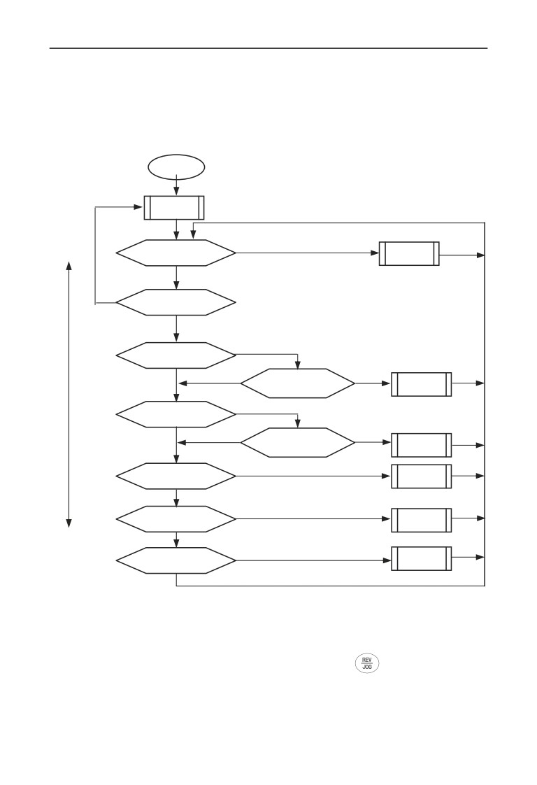
EN500/EN600 inverter have 6 kinds of run mode, following is in turn according
to their priority, jog run ĺclosed-loop run ĺPLC run ĺmulti-section speed runĺ
swing frequency run ĺcommon run. Shown as Fig.5-1.
Electrification
Waiting
state
Y
High priority
Any jog command˛
Jog run
N
N
Run command effective˛
Y
Y
Closed-loop effective˛
Y
Closed-loop invalidation
N
Closed-loop
N
terminal closed˛
run
Y
PLC effective˛
Y
PLC invalidation
N
N
terminal closed˛
PLC run
Y
Multi-section
Multi-section terminal effective?
run
N
Y
Traverse
Traverse run?
run
low priority
N
Y
Common
Common run?
run
N
Fig.5-1 Run mode
0:Jog run
Upon receiving jog run command (for instance, press the
key on keypad)
during waiting state, the inverter run at jog frequency (see function code
F01.25~F01.29).
1:
Closed-loop run
The inverter will come into closed-loop run mode when closed -loop run control
40
5 Run and operation explanation for inverter
effective parameter is set(F11.00=1or F12.001). Namely carry on PID adjustment
to specified value and feedback value(proportion integral differential calculation,
see F11 group function code) and PID adjuster output is inverter output frequency.
Can make closed-loop run mode ineffective and switch to lower level run mode by
multi-function terminal (function 31).
2:
PLC run
The inverter will enter into PLC run mode and run according to run mode preset(see
F10 group function code description) through setting PLC function effective
parameter(F10.00 last bit
0). Can make PLC run mode ineffective and switch to
lower level run mode by multi-function terminal (function 36).
3:multi-section speed run
By nonzero combination of multi-function terminal(5,6,7,8,function)ˈchoose
multi-section frequency 1~15(F10.31~F10.45) to run at multi-section speed.
4:swing frequency run
The inverter will enter into swing frequency run mode when swing frequency
function effective parameter(F13.00=1)is set. Set relevant swing frequency run
special parameter according to textile swing frequency craft to realize swing
frequency run.
5:common run
Common open loop run mode of general inverter.
In above 6 kinds of run mode except “jog run” the inverter can run according to
kinds of frequency setting method.
41
5 Run and operation explanation for inverter
5.2 Operation and use of key board
5.2.1 Keypad layout
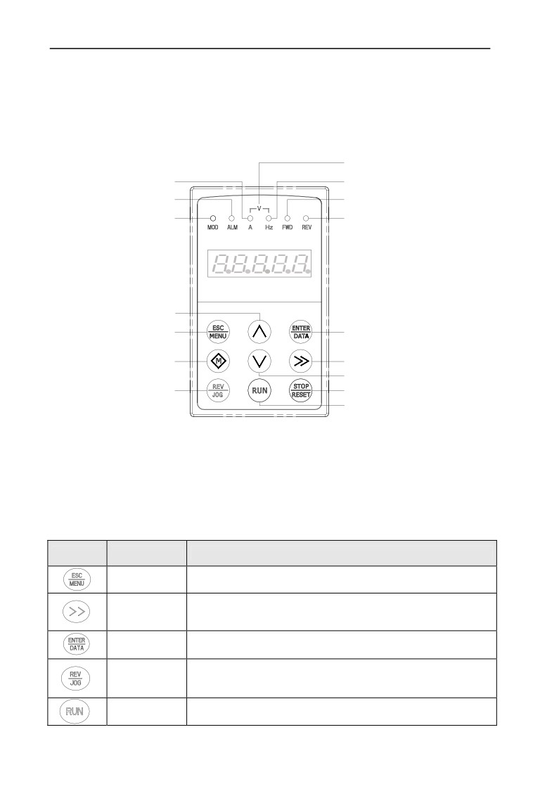
The operating keyboard is the main unit of frequency inverter to accept commands,
display parameters. Keyboard outline diagram shown in Figure 5-2.
Voltage indicator light
Current indicator light
Frequency indicator light
Failure alarm indicator light
Forward run indicator light
Mode indicator light
Reverse run indicator light
Increase key
Exit/Program key
Confirm/Data key
Multiple function key
Shift/Supervision key
Decrease key
Reverse/Jog key
Stop/Reset key
Forward run key
Fig.5-2 keypad layout sketch
5.2.2 Keypad function description
There are 9 key-presses on inverter keypad, and function definition of each key is
as shown in table 5-1.
Table 5-1 keypad function table
Key
Name
Function description
Program/Exit
Enter into or exit programming state
key
Shift/Supervisi
Can choose modification digit of set data under editor state˗
on key
can switch display status supervision parameter under other state
Function/Data
Enter into or exit programming state
key
Under keypad mode: to press this key can set reverse run or Jog run
Rev/Jog key
according to the 1st bit of parameter F00.15
Run key
Enter into forward run under keypad mode
42
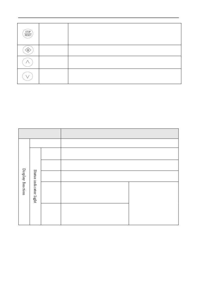
5 Run and operation explanation for inverter
In common run status the inverter will be stopped according to set mode
after pressing this key if run command channel is set as keypad stop
Stop/reset key
effective mode. The inverter will be reset and resume normal stop status
after pressing this key when the inverter is in malfunction status.
Multi-function
The specific function keys decided by tens digit of F00.15 see F00.15
key
parameter descriptions
Increasing
To increase data or function code (to press it continuously can
button
improve increasing speed)
Decreasing
To decrease data or function code (to press it continuously can
button
improve decreasing speed)
5.2.3 LED and indicator light
4 status indicator light: they are MOD(mode):ALM(alarm):FWD(forward run):
REV(reverse run)from left to right on the LED: their respective indicating meaning
is as shown in table 5-2.
Table 5-2 status indicator light description
Item
Function description
Digital display
Display current run status parameter and set parameter
Unit for relevant current digital displayed physical parameter(for
A, Hz, V
current is A:for voltage is V:for frequency is Hz)
This indicator light is lit in non-supervision status and extinguished
MOD
if no key pressed for a minute: then come back to supervision status
Alarm indicator light: indicate that the inverter is in over current or over
ALM
voltage suppressing status or failure alarm status currently
Forward run indicator light, indicate
that the inverter output forward phase
FWD
order and the connected motor rotate in
The inverter work in DC
forward direction
brake status if FWD,REV
Reverse run indicator light: indicate that
indicator light is lit at the
the inverter output reverse phase order
same time
REV
and the connected motor rotate in
reverse direction
5.2.4 Key board display status
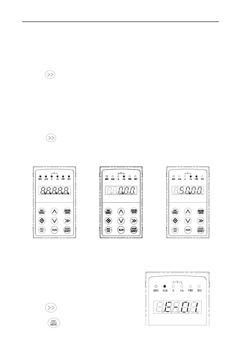
EN500/EN600 keypad display status is classified as Waiting status parameter display;
Function code parameter editing status display; Malfunction alarm status display; Run
status parameter display; Alarm state display in total 5 kinds of status. LED indicator
light will all be lit after the inverter electrified. Then enter into set frequency display. As
shown in Fig.5-3 a
43
5 Run and operation explanation for inverter
(1) Waiting parameter display status
The inverter is in waiting status and waiting status supervision parameter is
displayed on keyboard: normally parameter F00.13 decide which status supervision
parameter to be displayed. As shown in Fig.5-3 bˈ the indicator light shows the unit of
the parameter.
To press
key, it can display different waiting status supervision parameter
circularly: for detail please see C-00 to C-05 group supervision parameter details
decide by F00.07~F00.12.
(2) Run parameter display status
The inverter enters into run status when receiving effective run command and
normally parameter F00.13 decide which status supervision parameter to be displayed
on the keypad. As shown in Fig.5-3 cˈ the indicator light shows the unit of the
parameter.
To press
key can display run status supervision parameter circularly. For
detail please see C-00 To C-05 group supervision parameter details decide by
F00.01~F00.06 .
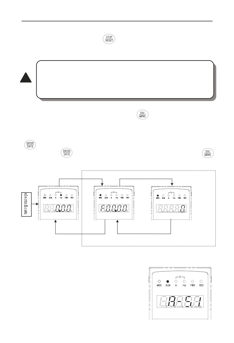
Set frequency
Output frequency
Fig.a Electrificationˈ
Fig.b waiting status, display
Fig.c run status: display run
display 8.8.8.8.8.
waiting status parameter
status parameter
Fig.5-3 inverter electrification: waiting: run status display
(3) Failure alarm display status
The inverter enters into failure alarm display
status upon detecting failure signal and display
failure code sparklingly(as shown in Fig.5-4);
To press
key can look over relative
parameter after stopping running˗
over current in accelerating
Can press
key to enter into program status
to see about F26 group parameter if want to search
Fig.5-4
44
5 Run and operation explanation for inverter
failure information.
Can carry on failure restoration by
key: control terminal or
communication command on the keypad after troubleshooting. Keep displaying
failure code if failure exist continuously.
For some serious failure, such as The earthing short circuit, Inverter
modules protect, over current, over voltage etc., must not carry on
failure reset forcibly to make the inverter run again without failure
!
elimination confirmed. Otherwise have danger of damaging the
inverter!
(4) Function code editing status
Under waiting, run or failure alarm status, press
key, can enter into editing
status(If user password is set, can enter into editing status after inputting the
password, see also F27.00 description and Fig.5-10)ˈand editing status is
displayed according to three classes menu mode, as shown in Fig. 5-5. To press
key can enter into one class by one class. Under function parameter display
status, to press
key to carry on parameter storage operation; To press
key can only come back to upper class menu without storing modified parameter.
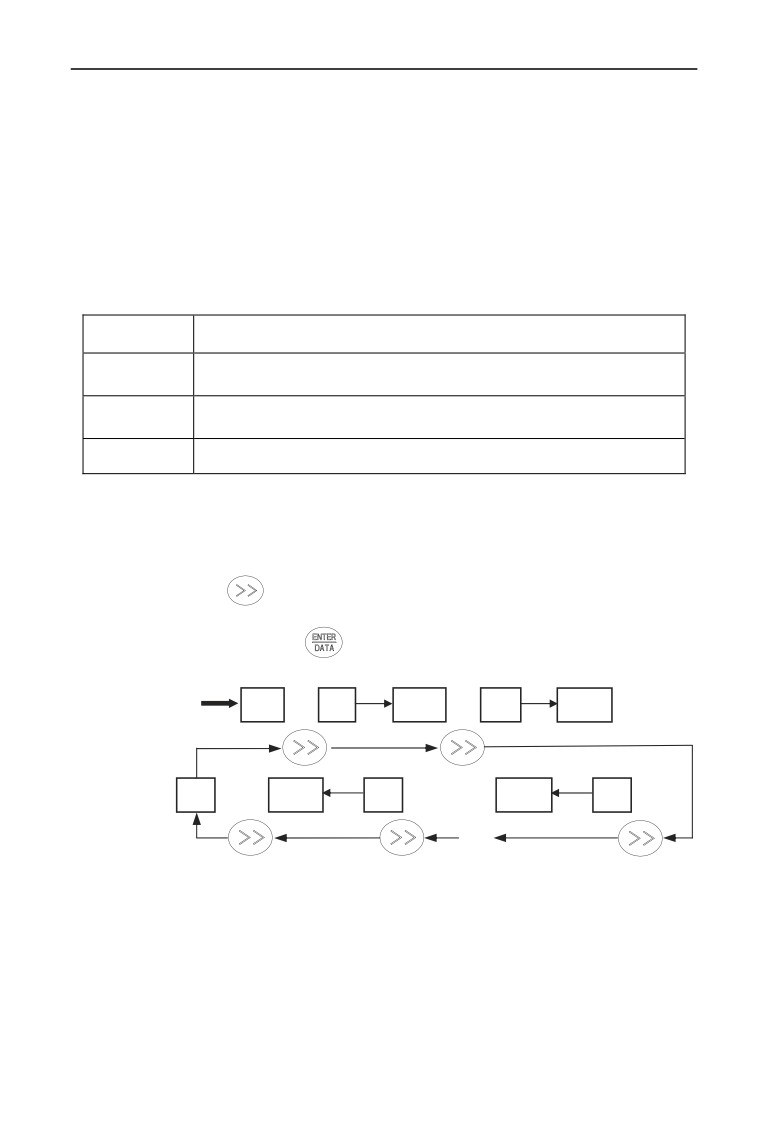
ESC/MENU
First class menu
ENTER/DATA
Second-class menu
Output freq.switch display
Para. group Display control
ESC/MENU
ESC/MENU
Waiting status parameter Display
or run status parameter display
or failure alarm display
Fig.5-5 keypad display status switching
(5) Alarm state display
When under running and standby situation:
It means enter failure alarm display status upon
detecting failure signal and display failure
code sparklingly (Fig5-6˅Inverter keeping
running state But this alarm display can not
be reset button eliminated: After only find
Same main/assist frequency channel
the cause of the alarm: in order to eliminate
Fig.5-6
45
5 Run and operation explanation for inverter
this factor Normal.
5.2.5 User Management Parameters
In order to facilitate the user parameter management: EN500/EN600 component
model parameter menu for display management. The parameters do not need to be
displayed can be shielded.
Ł Method parameter setting mode display.
By setting F00.00 = 0,1,2,3 respectively parameter mode is set: Basic menu mode:
menu mode Intermediate: Advanced menu mode and user menu mode.
Basic menu
F00,F01,F02,F03,F26
F00,F01,F02,F03,F04,F05,F06,F07,F08,F09,F10,F11,F12,F13,F14,
Middle menu
F15,F16,F18,F19,F26
Advance
F00,F01,F02,F03,F04,F05,F06,F07,F08,F09,F10,F11,F12,F13,F14,
menu
F15,F16,F17,F18,F19,F20,F21,F22,F23,F24,F25,F26,F27
User custom
F00.00 and F25 parameters group
5.2.6 Method for operating keypad
Can carry on various operation to the inverter through keypadˈ for example:
(1) Status parameter display switching:
After pressing key
,display C group status supervision parameter; after
displaying one supervision parameter code for 1 second will display this parameter
value automatically. Press key
will go back to supervision interface.
1s
1s
LED displayed content
0.00
C-01
Para.
C-02
Para.
Key-press operation
order
1s
1s
C-00
Para.
C-05
Para.
C-03
∫…∫
Fig.5-7 waiting status parameter display operating example
46
5 Run and operation explanation for inverter
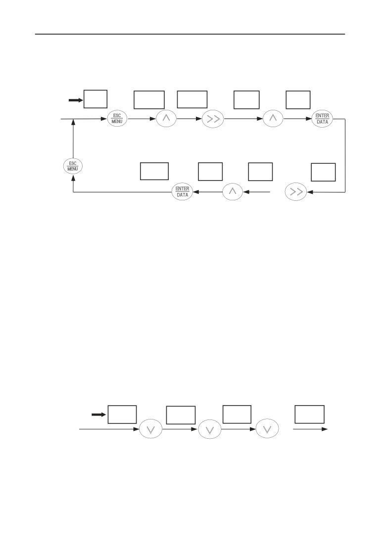
(2) Function code parameter setting
Take function code F01.01 modified from 5.00Hz to 6.00Hz as example.
Boldface in Fig.5-8 shows flickering digit.
LED displayed
0.00
F00.00
F01.00
F01.00
F01.01
content
Key-press
peration order
Move to the
Choose
Enter into
Choose
position to
function
Exit editing
editing Status
F01 group
be adjusted
code F01.01
status
display first-class
function code
menu
F01.02
006.00
005.00
005.00
…
Store modified
Parameter
Parameter
Function code
value: back to
confirmation,
modification,
modification,
first -class menu
Choose
Enter into
5ĺ6
Display next
parameter digit
second-class
function code
Fig.5-8 example for parameter setting and modification
Description: under second -class menu: if the parameter has no blinking digit, this
function code can’t be modified, possible reasons are as follows:
1> This function code shouldn’t be modified: for example actual detected status
parameter: run record parameter etc.;
2> This function code can’t be modified under run status and can be changed
after stopping running;
3> Parameter protected. All the function code can’t be modified when function
code F00.14=1 or 2ˈin order to avoid wrong operation. Need to set the
function code F00.14 to 0 if you want to edit function code parameter.
(3) Specified frequency adjustment for common run
Take example modifying specified frequency from 50.00Hz to 40.00Hz at
F01.06=1ˈF01.03=0 during running for explanation.
LED displayed content
50.00
49.99
45.00
40.00
Key-press
…
operation order
Stop pressing after set
Press decreasing
Adjust frequency
value reached: go back
button for one
based on
to normal display status
time
requirement
after 1s
Fig.5-9 set frequency adjustment operation example
(4) Jog run operation
For example: keypad as current run command channel: jog run frequency 5Hz:
waiting status.
47
5 Run and operation explanation for inverter
LED displayed
0.00
0.01
5.00
0.01
0.00
content
Press
Release
Waiting
Keep
Key-press
…
Waiting
operation order
Display
Display run
Output frequency
Output frequency
set frequency
output frequency
Fall down to 0Hz
Increased by 5Hz
Stop running
Fig.5-10 Jog run operating example
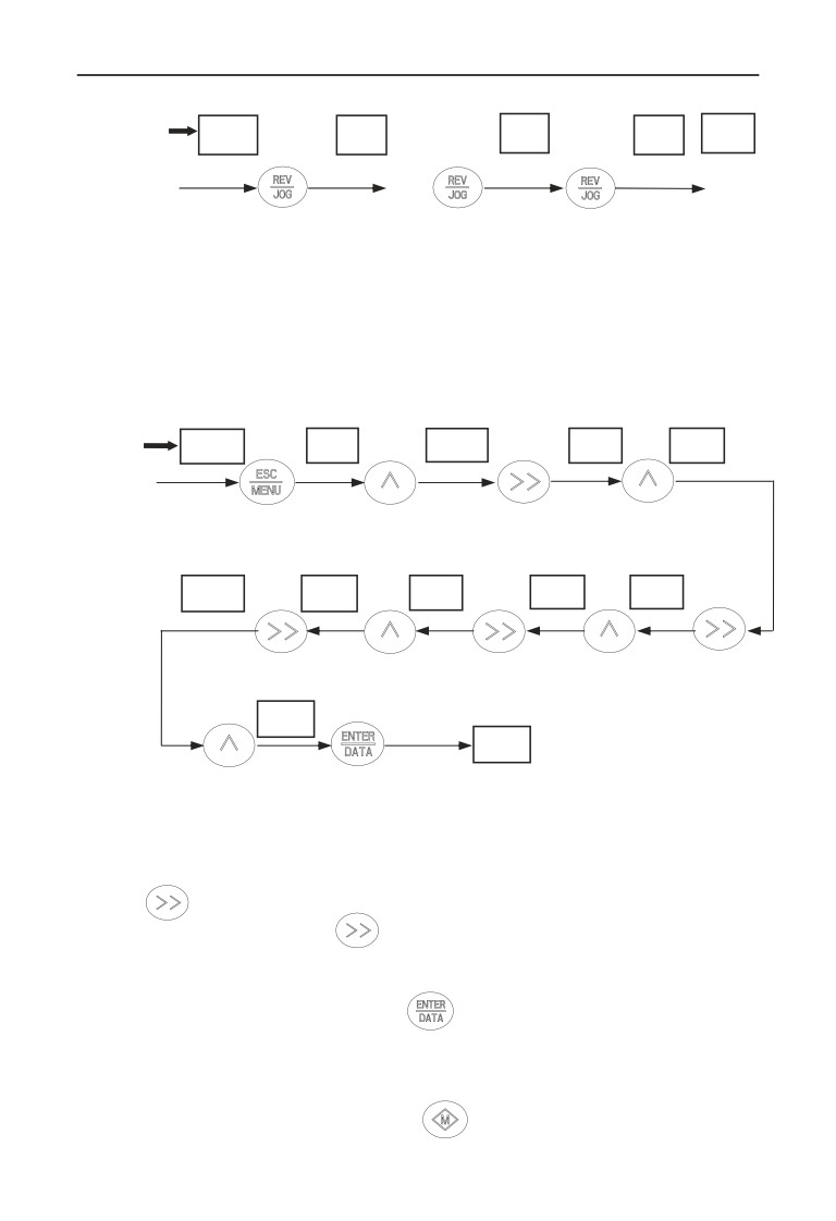
(5) Operation for entering to function code editing status after setting user
password
For example :“User password” F27 is set to“12345”. Boldfaced digit in Fig.5-11
shows blinking bit.
LED displayed
0.00
00000
10000
10000
12000
content
Key-press
operation order
Move cursor
Increase
None-editing
User password
At first last
position to
to“2”
status
effective: go into
Digit flash,
forth digit
password validation
Increase to“1”
status
12340
12340
12300
12300
12000
Move to
Increase
Move to
Increase
the unit
Move to third
to“4”
second digit
to“3”
12345
F27.00
Increase to“5”
Press confirmation
Key: pass validation,
Go into editing status
Fig.5-11 Inputting password to go into function code operation
(6) See about failure parameter under failure status:
If press
key under failure status the user can quickly locate to the F26 group
function code parameter. Press
can quickly switch value between F26.04 ~
F26.10 parameters and fault alarm, easy to view the fault records.
(7) Keypad key-press locking operation
Under monitoring situation, To press
for 2s,the keyboard will display
‘LOCH1’ˈnow the buttons on the keyboard are under locked. The detailed locked
situation is decided by the value of hundred unit of F00.14.
(8) Keypad key-press unlocking operation
1) Under locked keypad situation, press
key for 2s to unlock the keypad.
48
5 Run and operation explanation for inverter
2) Under locked keypad situation,if there is no
key, please press
key for 2s to unlock the keypad.
5.3 Inverter electrification
5.3.1 Check before electrification
Please carry on wiring based on operation requirement provided in “inverter
wiring” of this Service manual.
5.3.2 First electrification
Close input side AC power supply switch after correct wiring and power supply
confirmed: electrify the inverter and keypad LED display “8.8.8.8.8”,
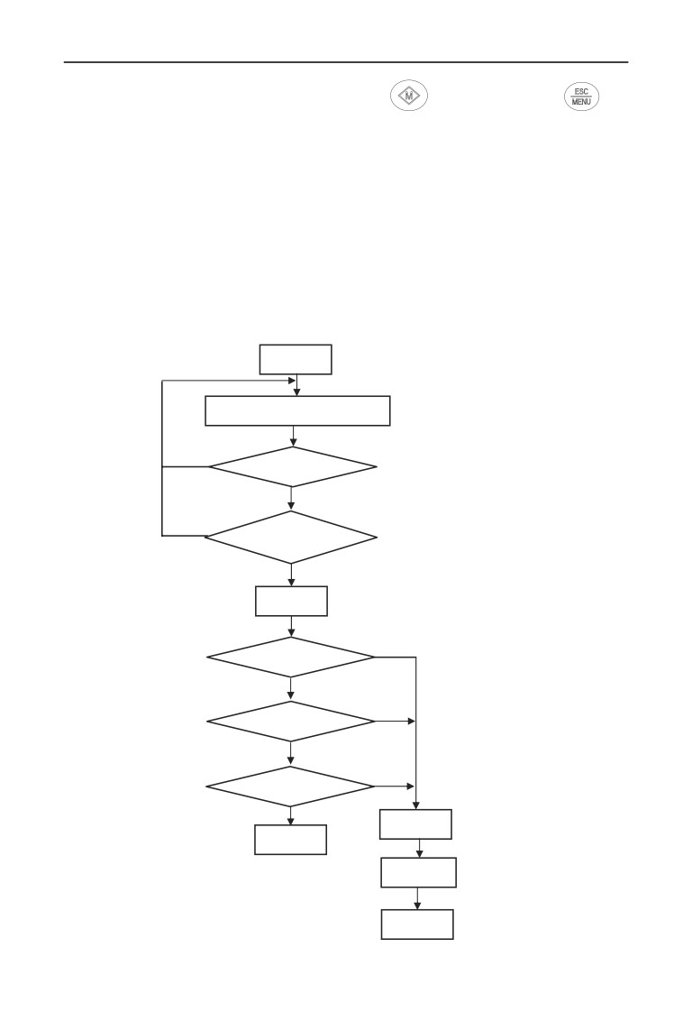
contactor closed normally: LED displayed set frequency shows that electrification
is finished. First electrification operation process is shown as Fig.5-12:
Start
Wiring based on 3.5 section
N
Wiring correct?
Y
N
Input voltage correct?
Y
Electrify
Y
N
Display 8.8.8.8.8.?
Y
N
Hear contactor closed sound˛
Y
N
Display 0.00Hz˛
Y
Failure
Success
Cut off power
check reason
Fig.5-12 first electrification operation flow
49
6 Function parameter schedule graph
6 Function parameter schedule graph
6.1 Symbol description
× ---- parameter can’t be changed in process of running
ż ---- parameter can be changed in process of running
---- read-only parameter, unmodifiable
6.2 Function parameter schedule graph
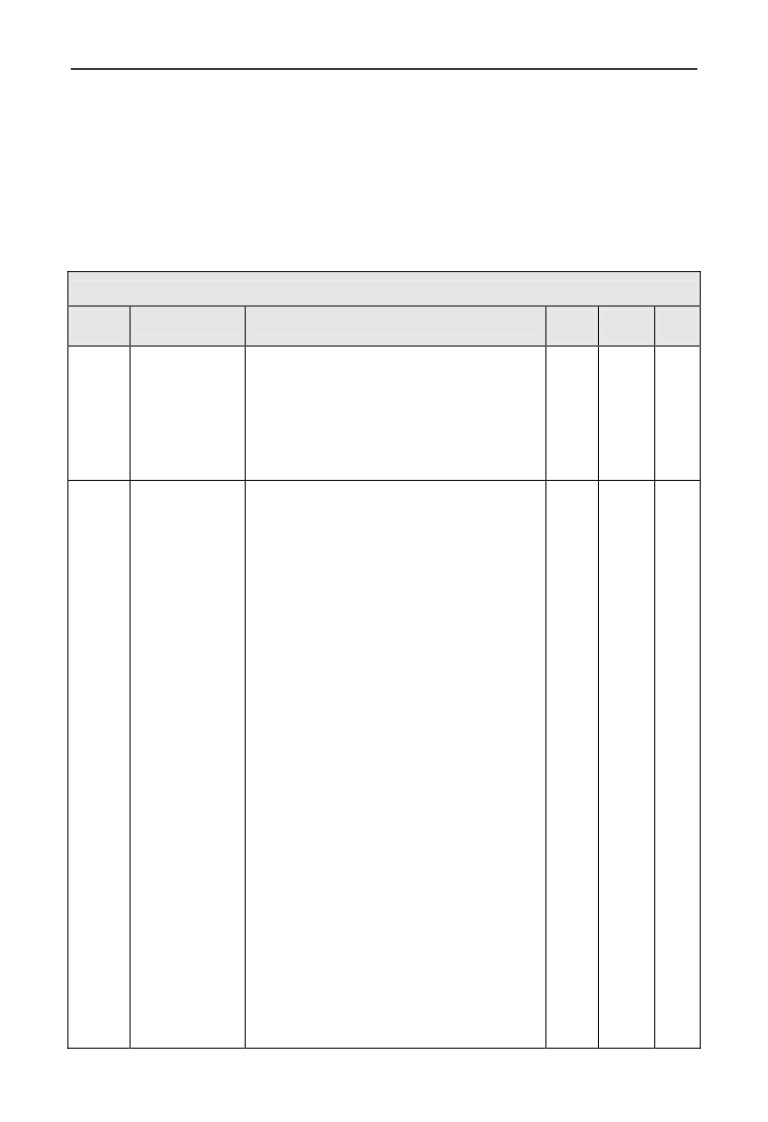
F00-System Parameter Group
Function
Min.
Factory
Modifi
Name
Set range
code
unit
Default
-cation
F00.00
Parameter group
0: Basic list mode(only displayF00~F03 basic control
1
0
ż
display control
parameter group and F26 fault record parameter
group.)
1: Middle list mode. Display all parameter except for
extension: virtual and reserve parameter group.
2: Senior list mode. All parameter display.
3: User list mode. Display parameter defined by user:
and monitor parameter: F00.00 display all the time.
F00.01
C-00 display
0: main setup frequency(0.01Hz)
1
51
ż
parameter selection
1: auxiliary setup frequency(0.01Hz)
when operation
2: setup frequency(0.01Hz)
3: output frequency(0.01Hz)
4: output current(0.1A)
5: output voltage(1V)
6: DC busbar voltage(0.1V)
7: motor speed(1 circle/min)
8: motor line velocity(1 circle/min)
9: inverter temperature(1℃)
10: run time already this time(0.1min)
11: current accumulate run time(1h)
12: current accumulate power-on time(1h)
13: inverter status
14: input terminal status
15: output terminal status
16: extension output terminal status
17: extension input terminal status
18: communication virtual input terminal status
19: internal virtual input node status
20: analog input AI1(after checkout)
(0.01V / 0.01mA)
21: analog input AI2(after checkout)
(0.01V / 0.01mA)
22: extension analog input EAI1(after checkout)
(0.01V / 0.01mA)
23: extension analog input EAI2(after checkout)
(0.01V / 0.01mA)
24: analog AO1 output(after checkout)
(0.01V /0.01mA)
25: analog AO2 output(after checkout)
(0.01V /0.01mA)
26: extension analog EAO1 output
(0.01V /0.01mA)
50
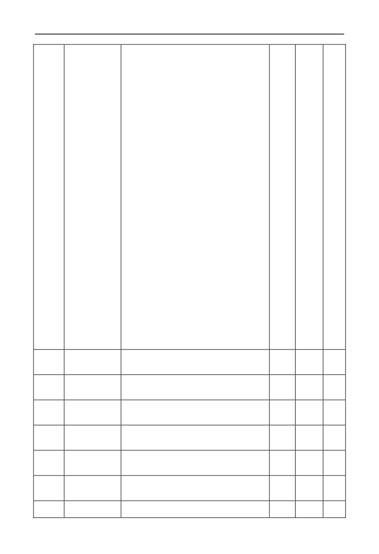
6 Function parameter schedule graph
27: extension analog EAO2 output(0.01V /0.01mA)
28: external pulse input frequency(before checkout)
(1Hz)
29: Reserved
30: process PID provide(0.01V)
31: process PID feedback(0.01V)
32: process PID deviation(0.01V)
33: process PID output(0.01Hz)
34: simple PLC current segment No.
35: external multi-speed current segment No.
36: constant pressure water supply provide pressure
(0.001Mpa)
37: constant pressure water supply feedback pressure
(0.001Mpa)
38: constant pressure water supply relay status
39: current length(1M)
40: accumulate length(1M)
41: current internal count value
42: current internal time value(0.1s)
43: run command setup channel(0:keyboard
1: terminal
2: communication)
44: main frequency provide channel
45: auxiliary frequency provide channel
46: rated current(0.1A)
47: rated voltage(1V)
48: rated power(0.1KW)
49: Reserved
50: Reserved
51: frequency after Acce/Dece(0.01Hz)
52: motor rotor frequency(0.01Hz)
53: current given torque(percentage relative to rated
torque, with direction)
54: current output torque(percentage relative to rated
torque, with direction)
55: torque current at present(0.1A)
56: flux current at present(0.1A)
57~65: Reserved
F00.02
C-01 display
Same as above
1
2
ż
parameter selection
when operation
F00.03
C-02 display
Same as above
1
4
ż
parameter selection
when operation
F00.04
C-03 display
Same as above
1
5
ż
parameter selection
when operation
F00.05
C-04 display
Same as above
1
6
ż
parameter selection
when operation
F00.06
C-05 display
Same as above
1
9
ż
parameter selection
when operation
F00.07
C-00 display
Same as above
1
2
ż
parameter selection
when stop
F00.08
C-01 display
Same as above
1
6
ż
parameter selection
51
6 Function parameter schedule graph
when stop
F00.09
C-02 display
Same as above
1
48
ż
parameter selection
when stop
F00.10
C-03 display
Same as above
1
14
ż
parameter selection
when stop
F00.11
C-04 display
Same as above
1
20
ż
parameter selection
when
stop
F00.12
C-05 display
Same as above
1
9
ż
parameter selection
when stop
F00.13
Power-on fault
0~5
1
0
ż
monitor parameter
selection
F00.14
Parameter
Units digit: Parameter modification operations
1
000
×
operation control
0: All parameters are allowed to be modified
1: Except current parameter, all other parameters are
not allowed to modify the
2: ExceptF01.01,F01.04and current parameter, all
other parameters are not allowed to be modified
Tens digit: Reset to factory defaults
0: No action.
1: All parameters return to default.(not include fault
record parameter group(F26 group) parameter).
2: Except for motor parameter: all parameters return
to default.(not include F15 and F26 group parameter).
3: Extension parameter return to default.(only
F21~F24 group parameter return to default).
4: Virtual parameter return to default.(only F20 group
parameter return to default).
5: Fault record return to default.(only fault record
parameter group(F26 group)parameter return to
default)
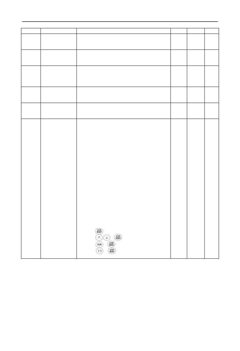
Hundreds digit: Key operation
0: All locked
1: Except
button: the others locked
2: Except
, button: the others locked
3: Except
, button: the others locked
4: Except
, button: the others locked
52
6 Function parameter schedule graph
F00.15
Button function
Units digit: panel
button selection
1
0001
ż
selection
0: Reversal command action button
1: Jog action button
Tens digit:
multi-function button function
selection
0: Invalid.
1: Jog run.
2: For/rev switching.
3: Free stop.
4: Switching to run command provide mode as the
setup order of F00.16.
5: Forward/Reverse Torque Switching
6~9: Reserved
Hundreds digit: terminal run command control
0: Keyboard
button invalid
1: Keyboard
button valid
Thousands digit: communication run command control
0: Keyboard
button invalid
1: Keyboard
button valid
F00.16
Multi-function key
0: Keyboard controlĺ terminal controlĺ
1
0
ż
run command
communication control
channel switching
1: Keyboard controlĸĺterminal control
order selection
2: Keyboard controlĸĺcommunication control
3: Terminal controlĸĺcommunication control
F00.17
Motor speed
0.1~999.9%
0.1%
100.0%
ż
display coefficient
F00.18
Line velocity
0.1~999.9%
0.1%
1.0%
ż
display coefficient
F00.19
Extended Port Parts
0: Invalid
1
0
×
set
1: Reserved
2: Multi pump water supply card
3: Incremental PG encoder
4~10: Reserved
F00.20
Analog input
Units digit:AI1 configuration
1
0000
×
terminal
0: 0~10V input
configuration
1: 4~20mA input
Tens digit: AI2 configuration
0: -10~10V input
1: 4~20mA input
Hundreds digit: EAI1 configuration
0: 0~10V input
1: -10~10V input
2: 4~20mA input
Thousands digit: EAI2 configuration
0: 0~10V input
1: -10~10V input
2: 4~20mA input
F00.21
Analog output
Units digit: AO1 configuration
1
0000
×
terminal
0: 0~10V output
configuration
1: 4~20mA output
Tens digit: AO2 configuration
0: 0~10V output
1: 4~20mA output
Hundreds digit: EAO1 configuration
53
6 Function parameter schedule graph
0: 0~10V output
1: 4~20mA output
Thousands digit: EAO2 configuration
0: 0~10V output
1: 4~20mA output
F00.22
Y output
Units digit~ Hundreds digit: reserved
1
0000
×
terminal
Thousands digit: Y4 output configuration
configuration
0: Open collector output
1: DO output
F00.23
G/P type setup
0: G type.
1
0
×
1: P type.
Note: P type is only for V/F control
F00.24
Motor control mode
0: V/F control(object to torque control)
1
0
×
1: speed less sensor vector control 1(compare to
speed less sensor vector control 2,this control mode
is more suitable for asynchronous motor160KW,
support speed and vector control)
2: speed sensor vector control(support asynchronous
motor speed and torque control)
3:speed less sensor vector control 2(only support
asynchronous motor speed control,this control mode
is more suitable for motor 185KW)
F00.25
Monitor parameter
The same as parameter F00.01
1
2
ż
2 selection
F00.26
Busbar voltage
0.900~1.100
1
1.000
ż
adjustment
coefficient
F00.27
Parameters copying
Units digit:Language(only valid for LCD keypad)
1
00
×
and Language
0: Chinese
selection
1: English
2: Reserved
Tens digit:parameter upload and download (valid for
LCD and digital potentiometer keypad)
0: Inaction
1: parameter upload
2: parameter download
F01-Basic Run Function Parameter Group
Function
Min.
Factory
Modifi
Name
Set Range
Code
Unit
Default
-cation
F01.00
Main frequency
0: Operation keyboard digital setup
1
0
ż
input channel
1: AI1 analog setup
selection
2: AI2 analog setup
3:Terminal UP/DOWN adjusting setup
4:Communication provide.
5:EAI1 analog setup.
6:EAI2 analog setup
7:High speed pulse setup X8 terminal need choose the
suitable function)
8:Terminal pulse setup(X8 terminal need choose the
suitable function)
9:Terminal encoder setup(X1:X2 connect the encoder
punctuation input)
10~14: Reserved
F01.01
Main frequency
0.00Hz~upper limit frequency
0.01Hz
50.00Hz
ż
54
6 Function parameter schedule graph
digital setup
F01.02
Main frequency
Only when parameter F01.00=0:3:4 valid.
1
00
ż
digital control
Units digit: power down reserve setup
0:Main frequency power down reserve.
1:Main frequency power down no reserve.
Tens digit: halt reserve setup
0:Halt main frequency hold
1:Halt main frequency recovery F01.01
F01.03
Auxiliary
0: Operation keyboard digital setup
1
20
ż
frequency input
1: AI1 analog setup
channel select
2: AI2 analog setup
3:Terminal UP/DOWN adjusting setup
4:Communication provide.
5:EAI1 analog setup.
6:EAI2 analog setup
7:High speed pulse setup X8 terminal need choose the
suitable function)
8:Terminal pulse setup(X8 terminal need choose the
suitable function)
9:Terminal encoder setup(X1:X2 connect the encoder
punctuation input)
10~20: Reserved
F01.04
Auxiliary
0.00Hz~upper limit frequency
0.01Hz
0.00Hz
ż
frequency digital
setup
F01.05
Auxiliary
Units digit: power down reserve setup
1
11
ż
frequency digital
0:Auxiliary frequency power down reserve.
control
1:Auxiliary frequency power down no reserve.
Tens digit: halt reserve setup
0:Halt auxiliary frequency hold.
1:Halt auxiliary frequency recovery parameter F01.04
F01.06
Main and
0:Main frequency (complex frequency of current is
1
0
ż
auxiliary provide
main frequency).
calculating setup
1: Auxiliary frequency(complex frequency of current
is auxiliary frequency.)
2: Plus(polarity oppose of complex and main
frequency,complex frequency is zero).
3:Minus(polarity oppose of complex and auxiliary
frequency,complex frequency is zero).
4:Multiplication(polarity opposed of main and
auxiliary frequency: complex frequency is zero).
5:Max(the max frequency of main and auxiliary
absolute value).
6:Min(the min frequency of main and auxiliary
absolute value).
7:Selection no-zero value(auxiliary is not negative,
main frequency prior;auxiliary is negative,complex
frequency is zero).
F01.07
Auxiliary
0.00~10.00
0.01
1.00
ż
frequency provide
coefficient
F01.08
Coefficient after
0.00~10.00
0.01
1.00
ż
complex of main
and auxiliary
frequency
F01.09
Auxiliary
0:Relative upper limit frequency.
1
0
ż
frequency range
1:Relative main frequency.
55
6 Function parameter schedule graph
selection
F01.10
Auxiliary
0.00~1.00
0.01
1.00
ż
frequency source
scope
F01.11
upper limit
Low limit frequency~600.00Hz
0.01Hz
50.00Hz
×
frequency
F01.12
Low limit
0.00Hz~upper limit frequency
0.01Hz
0.40Hz
×
frequency
F01.13
Low limit
0:As low limit frequency run.
1
2
×
frequency run
1:As setting frequency run.
mode
2:As zero frequency run.
3:Sleep: PWM clocked at sleep mode.
F01.14
Sleep run hysteresis
0.01Hz~upper limit frequency(This function can be
0.01Hz
0.01Hz
ż
frequency
used to finish the sleep mode function, realizing
energy-saving operation process, and the hysteresis
width can avoid inverter starting frequently in
threshold)
F01.15
Run command
0:Operation keyboard run control.
1
0
ż
channel selection
1:Terminal run command control
2:Communication run command control.
F01.16
Run direction
Units digit: Keyboard command for/rev setup(only
1
00
ż
setup
valid to keyboard inching command)
0:Forward
1:Reverse
Tens digit: for/rev forbid(suitable for all command
channel,not include inching function)
0:For/rev available.
1:Reverse not available( imposing on reverse,stop as
the halt mode).
2:Forward not available( imposing on
forward,stop as the halt mode)
F01.17
Acceleration time 1
1~60000(Acceleration time is interval accelerate from
Base on
zero frequency to upper limit frequency)
1
motor
ż
type
F01.18
Deceleration time 1
1~60000(deceleration time is the interval decelerate
Base on
from upper limit frequency to zero frequency.)
1
motor
ż
type
F01.19
Acc/Dece time unit
0:0.01s
1
1
×
1:0.1s
2:1s
F01.20
Acc/Dece mode
0:Line acc/Dece mode.
1
0
×
selection
1:S curve acc/Dece mode.
F01.21
S curve
10.0%~50.0%((Acceleration/deceleration time)
0.1%
20.0%
ż
acceleration
S curve deceleration start time+ S curve deceleration
initiation segment
raise time 90% )
time
F01.22
S curve
10.0%~70.0%(Acceleration/deceleration time)
0.1%
60.0%
ż
acceleration
up
S curve acceleration start time+ S curve acceleration
segment time
raise time 90% )
F01.23
S curve
10.0%~50.0%(Acceleration/deceleration time)
0.1%
20.0%
ż
deceleration
S curve acceleration start time+ S curve acceleration
initiation segment
raise time 90% )
time
F01.24
S curve
10.0%~70.0%(Acceleration/deceleration time)
0.1%
60.0%
ż
deceleration up
S curve acceleration start time+ S curve acceleration
segment time
raise time 90% )
F01.25
Keyboard jog run
0.00Hz~upper limit frequency
0.01Hz
5.00Hz
ż
56
6 Function parameter schedule graph
frequency
F01.26
Terminal jog run
0.00Hz~upper limit frequency
0.01Hz
5.00Hz
ż
frequency
F01.27 Jog interval time
0.0~100.0s
0.1s
0.0s
ż
F01.28
Jog acceleration
0.1~6000.0s
0.1s
20.0s
ż
time
F01.29
Jog deceleration
0.1~6000.0s
0.1s
20.0s
ż
time
F02-Start, stop, forward/reverse, brake function parameter group
Function
Min.
Factory
Modifi
Name
Set Range
Code
Unit
Default
-cation
F02.00
Start running
0: Start from starting frequency
1
0
×
mode
1: First brake and then start from starting
frequency
2: Start by revolving speed tracking
F02.01
Starting delay
0.0~60.0s
0.1s
0.0s
×
time
F02.02
Starting frequency
0.0~10.00Hz
0.01Hz
0.00Hz
×
F02.03
Starting frequency
0.0~60.0s
0.1s
0.0s
×
duration time
F02.04
DC braking
0.0~100.0%(G type inverter rated current)
0.1%
30.0%
×
current when
starting
F02.05
DC braking
0.0~30.0s
0.1s
0.0s
×
time when
starting
F02.06
Speed track
0: Current setting frequency.
1
2
×
starting frequency
1: Running frequency before power down.
selection
2:Speed track auxiliary starting frequency.
F02.07
Speed track
0.00Hz~upper limit frequency
0.01Hz
10.00Hz
×
auxiliary starting
frequency
F02.08
Speed track
0.00~10.00s
0.01s
0.10s
×
starting waiting
time
F02.09
Speed track current
1~20
1
2
×
control coefficient
F02.10
Speed track
0.1~30.0(V/F control unit is 1 second;SVC
0.1
4.0
×
searching speed
control unit is 0.1 second)
time
F02.11
Stop mode
0: Deceleration stop.
1
0
ż
1: Free stop
2: Deceleration + DC braking stop.
F02.12
Deceleration stop
0.00~upper limit frequency(This parameter is
0.01Hz
0.00Hz
×
holding frequency
only valid for stop mode 0.)
F02.13
Deceleration stop
0.00~10.00s
0.01s
0.00s
×
holding time
F02.14
Stop DC braking starting
0.00~15.00Hz
0.01Hz
0.00Hz
×
frequency
F02.15
stop DC braking waiting
0.00~30.00s
0.01s
0.00s
×
time
F02.16
Stop DC braking current
0.0~100.0%(G type inverter rated current)
0.1%
0.0%
×
F02.17
Stop DC braking time
0.0~30.0s
0.1s
0.0s
×
F02.18
Stop auxiliary braking
0.0~100.0%(G type inverter rated current)
0.1%
0.0%
×
57
6 Function parameter schedule graph
current
F02.19
Stop auxiliary braking
0.0~100.0s
0.1s
0.0s
×
time
F02.20
Forward/reverse dead
0.0~3600.0s
0.1s
0.0s
×
zone time
F02.21
Forward/reverse switching
0: Over zero switchover
1
0
×
mode
1: Over starting frequency switchover
F02.22
Energy consumption
0:No energy consumption braking
1
0
ż
braking selection
1:Energy consumption braking.
F02.23
Energy consumption
115.0~145.0%(rated busbar voltage)
0.1%
125.0%
ż
braking voltage
F02.24
Energy consumption
0.0~100.0%
0.1%
100.0%
ż
braking use rate
F02.25 Encryption time
0~65535h
1
0
ż
F02.26 Reserved
F03-V/F control parameter group
Function
Min.
Factory
Modifi
Name
Set Range
Code
Unit
Default
-cation
F03.00
V/F curve set
0: Constant torque curve
1
0
×
1: Degression torque curve 1 (2.0 power)
2: Degression torque curve 1 (1.7 power)
3: Degression torque curve 3 (1.2 power)
4: User self-defined setting V/F curve
(Confirmed by F03.04~F03.11)
F03.01
Torque boost mode
0:Manual boost.
1
0
ż
1:Auto torque boost
F03.02
Torque boost
0.0~12.0%
0.1%
Base on
ż
motor
type
F03.03
Torque boost cut-off
0.0~100.0%(motor rated frequency)
0.1%
100.0%
ż
frequency
F03.04
V/F frequency value 0
0.00~V/F frequency value 1
0.01Hz
10.00Hz
×
F03.05
V/F voltage value 0
0.00~V/F voltage value 1
0.01%
20.00%
×
F03.06
V/F frequency value 1
V/F frequency value 0~V/F frequency value 2
0.01Hz
20.00Hz
×
F03.07
V/F voltage value 1
V/F voltage value 0~V/F voltage value 2
0.01%
40.00%
×
F03.08
V/F frequency value 2
V/F frequency value 1~V/F frequency value 3
0.01Hz
25.00Hz
×
F03.09
V/F voltage value 2
V/F voltage value 1~V/F voltage value 3
0.01%
50.00%
×
F03.10
V/F frequency value 3
V/F frequency value 2~upper limit frequency
0.01Hz
40.00Hz
×
F03.11
V/F voltage value 3
V/F voltage value
2~100.00%( motor rated
0.01%
80.00%
×
voltage)
F03.12
V/F oscillation
0~255
1
10
ż
suppression factor
F04-Auxiliary running parameter group
Function
Min.
Factory
Modifi
Name
Set Range
Code
Unit
Default
-cation
F04.00 Jump freq.
1
0.00Hz~upper limit frequency
0.01Hz
0.00Hz
×
F04.01 Jump freq.
1 range
0.00Hz~upper limit frequency
0.01Hz
0.00Hz
×
F04.02 Jump freq.
2
0.00Hz~upper limit frequency
0.01Hz
0.00Hz
×
F04.03 Jump freq.
2 range
0.00Hz~upper limit frequency
0.01Hz
0.00Hz
×
F04.04 Jump freq.
3
0.00Hz~upper limit frequency
0.01Hz
0.00Hz
×
F04.05 Jump freq.
3 range
0.00Hz~upper limit frequency
0.01Hz
0.00Hz
×
58
6 Function parameter schedule graph
F04.06
Slip freq. gain
0.0~300.0%
0.1%
0.0%
×
Slip compensation
0.0~250.0%
F04.07
0.1%
100.0%
×
limit
Slip compensation
0.1~25.0s
F04.08
0.1s
2.0s
×
time constant
F04.09
Carrier freq.
0.5~16.0K
0.1K
Based
ż
on motor
type
F04.10
PWM optimized
Units digit: Carrier freq. is adjusted
1
0110
×
adjustment
automatically according to temperature
0: Banned.
1: Allowed.
Tens digit: low speed carrier freq. limit mode
0: No limit.
1: Limit.
Hundreds digit: carrier wave modulation system
0: 3 phase modulation.
1: 2 phase and 3 phase modulation.
Thousands digit: Asynchronous modulation:
synchronization mode (valid under V/F control)
0:Asynchronous modulation.
1:Synchronous modulation (under 85Hz:
Asynchronous modulation).
F04.11
AVR function
0: No action
1
0
×
1: Action all the time
2: No action only during deceleration
F04.12
Reserved
F04.13
Automatic energy-saving
0: No action
1
0
×
operation
1: Action
F04.14
Acceleration time 2 and 1
0.00Hz~upper limit frequency
0.01Hz
0.00Hz
×
switchover frequency
F04.15
Deceleration time 2 and 1
0.00Hz~upper limit frequency
0.01Hz
0.00Hz
×
switchover frequency
F04.16
Acceleration time 2
1~60000
1
200
ż
F04.17
Deceleration time 2
1~60000
1
200
ż
F04.18
Acceleration time 3
1~60000
1
200
ż
F04.19
Deceleration time 3
1~60000
1
200
ż
F04.20
Acceleration time 4
1~60000
1
200
ż
F04.21
Deceleration time 4
1~60000
1
200
ż
F04.22
Acceleration time 5
1~60000
1
200
ż
F04.23
Deceleration time 5
1~60000
1
200
ż
F04.24
Acceleration time 6
1~60000
1
200
ż
F04.25
Deceleration time 6
1~60000
1
200
ż
F04.26
Acceleration time 7
1~60000
1
200
ż
F04.27
Deceleration time 7
1~60000
1
200
ż
F04.28
Acceleration time 8
1~60000
1
200
ż
F04.29
Deceleration time 8
1~60000
1
200
ż
F04.30
Acceleration time 9
1~60000
1
200
ż
F04.31
Deceleration time 9
1~60000
1
200
ż
F04.32
Acceleration time 10
1~60000
1
200
ż
F04.33
Deceleration time 10
1~60000
1
200
ż
F04.34
Acceleration time 11
1~60000
1
200
ż
F04.35
Deceleration time 11
1~60000
1
200
ż
F04.36
Acceleration time 12
1~60000
1
200
ż
F04.37
Deceleration time 12
1~60000
1
200
ż
F04.38
Acceleration time 13
1~60000
1
200
ż
59
6 Function parameter schedule graph
F04.39 Deceleration time 13
1~60000
1
200
ż
F04.40 Acceleration time 14
1~60000
1
200
ż
F04.41 Deceleration time 14
1~60000
1
200
ż
F04.42 Acceleration time 15
1~60000
1
200
ż
F04.43 Deceleration time 15
1~60000
1
200
ż
F05-Terminal correlative function parameter group
Function
Min.
Factory
Modifi
Name
Set Range
Code
Unit
Default
-cation
F05.00
protocol selection
0: Modbus protocol .
1
0
×
1: Reserved
2: Profibus protocol .(Extend effective)
3: CANlink protocol .(Extend effective)
4: CANopen protocol .(Extend effective)
5: Free protocol 1.(Can realize all the function
parameter modification of EN500/EN600)
6: Free protocol 2.(Can realize part of the
function parameter modification of
EN500/EN600)
F05.01
Baud rate configuration
Units digit: Free protocol and Modbus Baud rate
1
005
×
selection
0: 300BPS
1: 600BPS
2: 1200BPS
3: 2400BPS
4: 4800BPS
5: 9600BPS
6: 19200BPS
7: 38400BPS
8: 57600BPS
Tens digit: Profibus-DP Baud rate selection
0: 115200BPS
1: 208300BPS
2: 256000BPS
3: 512000BPS
Hundreds digit: CanLink and CANopen Baud
rate selection
0: 20K
1: 50K
2: 100K
3: 125K
4: 250K
5: 500K
6: 1M
F05.02
Data format
Units digit: Free protocol and Modbus protocol
1
000
×
data format 0:1-8-1 format,no parity,RTU
1: 1-8-1 format,even parity,RTU
2: 1-8-1 format,odd parity,RTU
3: 1-7-1 format,no parity,ASCII
4: 1-7-1 format,even parity,ASCII
5: 1-7-1 format,odd parity,ASCII
Tens digit: Profibus_DP protocol data format
0: PPO1 communication format
1: PPO2 communication format
2: PPO3 communication format
3: PPO5 communication format
60
6 Function parameter schedule graph
Hundreds digit: Modbus agreement or free
protocol response selection
0:respond mainframe demand, and respond data
package
1:respond mainframe demand and without
response
F05.03
Local address
0~247,
1
1
×
this function code is used to identify inverter’s
address: among which 0 is broadcast address.
When setting broadcast address: it can only
receive and execute upper computer broadcast
command: while cannot respond to
upper
computer.
F05.04
Communication overtime
0.0~1000.0s
0.1s
0.0s
ż
checkout
time
F05.05
Communication error
0.0~1000.0s
0.1s
0.0s
ż
checkout time
F05.06
Local response delay time
0~200ms(Modbus effective)
1ms
5ms
ż
F05.07
Main & sub inverter
0~500%
1%
100%
ż
communication frequency
setting percentage
F05.08
communication virtual
00~FFH
1
00H
ż
input terminal enabled
Bit0 : CX1 virtual input terminal enabled
0: forbidden
1 : enabled
Bit1: CX2 virtual input terminal enabled
0: forbidden
1: enabled
Bit2: CX3 virtual input terminal enabled
0: forbidden
1: enabled
Bit3: CX4 virtual input terminal enabled
0: forbidden
1: enabled
Bit4: CX5 virtual input terminal enabled
0: forbidden
1: enabled
Bit5: CX6 virtual input terminal enabled
0: forbidden
1: enabled
Bit6: CX7 virtual input terminal enabled
0: forbidden
1: enabled
Bit7: CX8 virtual input terminal enabled
0: forbidden
1: enabled
F05.09
Communication virtual
0: Independent node.
1
0
ż
input terminal joining
1: Terminal node.
node
F05.10
Communication virtual
0~90
1
0
ż
terminal CX1 function
F05.11
Communication virtual
0~90
1
0
ż
terminal CX2 function
F05.12
Communication virtual
0~90
1
0
ż
terminal CX3 function
F05.13
Communication virtual
0~90
1
0
ż
61
6 Function parameter schedule graph
terminal CX4 function
F05.14
Communication virtual
0~90
1
0
ż
terminal CX5 function
F05.15
Communication virtual
0~90
1
0
ż
terminal CX6 function
F05.16
Communication virtual
0~90
1
0
ż
terminal CX7 function
F05.17
Communication virtual
0~90
1
0
ż
terminal CX8 function
F05.18
Input mapping application
F00.00~F26.xx
0.01
25.00
ż
parameter 1
F05.19
Input mapping application
F00.00~F26.xx
0.01
25.00
ż
parameter 2
F05.20
Input mapping application
F00.00~F26.xx
0.01
25.00
ż
parameter 3
F05.21
Input mapping application
F00.00~F26.xx
0.01
25.00
ż
parameter 4
F05.22
Input mapping application
F00.00~F26.xx
0.01
25.00
ż
parameter 5
F05.23
Input mapping application
F00.00~F26.xx
0.01
25.00
ż
parameter 6
F05.24
Input mapping application
F00.00~F26.xx
0.01
25.00
ż
parameter 7
F05.25
Input mapping application
F00.00~F26.xx
0.01
25.00
ż
parameter 8
F05.26
Input mapping application
F00.00~F26.xx
0.01
25.00
ż
parameter 9
F05.27
Input mapping application
F00.00~F26.xx
0.01
25.00
ż
parameter 10
F05.28
Reserved
F05.29
Reserved
F05.30
Reserved
F05.31
Reserved
F05.32
Reserved
F05.33
Reserved
F05.34
Reserved
F05.35
Reserved
F05.36
Reserved
F05.37
Reserved
F05.38
Reserved
F05.39
Reserved
F06-Setting curve parameter group
Function
Min.
Factory
Modifi
Name
Set Range
Code
Unit
Default
-cation
F06.00
Setting curve
Units digit: AI1 curve selection
1
0000
ż
selection
0: curve 1
1: curve 2
2: curve 3
Tens digit: AI2 curve selection: The same as
Units digit
Hundred digit: rapid pulse curve selection: The
same as Units digit
Thousands digit: pulse width setting curve
62
6 Function parameter schedule graph
selection: The same as Units digit
F06.01
Curve 1 min. setting
0.0%~curve 1 inflexion setting
0.1%
0.0%
ż
F06.02
Corresponding physical
0.0~100.0%
0.1%
0.0%
ż
quantity of curve 1 min.
setting
F06.03
Curve 1 inflexion setting
Curve 1 min. setting ~ curve 1 Max. setting
0.1%
50.0%
ż
F06.04
Corresponding physical
0.0~100.0%
0.1%
50.0%
ż
quantity of curve 1
inflexion setting
F06.05
Curve 1 Max. setting
Curve 1 inflexion setting ~ 100.0%, 100.0% is
0.1%
100.0%
ż
corresponding to 5V Input AD terminal
F06.06
Corresponding physical
0.0~100.0%
0.1%
100.0%
ż
quantity of curve 1 Max.
setting
F06.07
Curve 2 min. setting
0.0%~curve 2 inflexion setting
0.1%
0.0%
ż
F06.08
Corresponding physical
0.0~100.0%
0.1%
0.0%
ż
quantity of curve 2 min.
setting
F06.09
Curve 2 inflexion setting
Curve 2 min. setting ~ curve 2 Max. setting
0.1%
50.0%
ż
F06.10
Corresponding physical
0.0~100.0%
0.1%
50.0%
ż
quantity of curve 2
inflexion setting
F06.11
Curve 2 Max. setting
Curve 2 inflexion setting~100.0%
0.1%
100.0%
ż
F06.12
Corresponding physical
0.0~100.0%
0.1%
100.0%
ż
quantity of curve 2 Max.
setting
F06.13
Curve 3 min. setting
0.0%~curve 3 inflexion 1 setting
0.1%
0.0%
ż
F06.14
Corresponding physical
0.0~100.0%
0.1%
0.0%
ż
quantity of curve 3 min.
setting
F06.15
Curve 3 inflexion 1 setting
Curve 3 min. setting ~ curve 3 inflexion 2
0.1%
30.0%
ż
setting
F06.16
Corresponding physical
0.0~100.0%
0.1%
30.0%
ż
quantity of curve 3
inflexion 1 setting
F06.17
Curve 3 inflexion 2 setting
Curve 3 inflexion 1 setting ~ curve 3 Max.
0.1%
60.0%
ż
setting
F06.18
Corresponding physical
0.0~100.0%
0.1%
60.0%
ż
quantity of curve 3
inflexion 2 setting
F06.19
Curve 3 Max. setting
Curve 3 inflexion 1 setting~100.0%
0.1%
100.0%
ż
F06.20
Corresponding physical
0.0~100.0%
0.1%
100.0%
ż
quantity of curve 3 Max.
setting
F06.21
Curve lower than min.
Units digit: curve 1 setting
1
11111
ż
input corresponding
0: Corresponds to min. setting
selection
corresponding physical quantity.
1: 0.0% of the corresponding physical
quantity.
Tens digit: curve 2 setting
Same as units digit.
Hundreds digit: curve 3 setting
Same as units digit.
Thousands digit: extended curve 1
Same as units digit.
63
6 Function parameter schedule graph
Ten thousands digit: extended curve 2
Same as units digit.
F07-Analog , Pulse input function parameter group
Function
Min.
Factory
Modifi
Name
Set Range
Code
Unit
Default
-cation
F07.00
AI1 input filter time
0.000~9.999s
0.001s
0.050s
×
F07.01
AI1 setting gain
0.000~9.999
0.001
1.004
ż
F07.02
AI1 setting bias
0.0~100.0%
0.1%
0.5%
ż
F07.03
AI2 input filter time
0.000~9.999s
0.001
0.050s
×
F07.04
AI2 setting gain
0.000~9.999
0.001
1.003
ż
F07.05
AI2 setting bias
0.0~100.0%
0.1%
0.1%
ż
F07.06
Analog setting bias
Units digit: AI1 setting bias polarity
1
01
ż
polarity
0: Positive polarity.
1: Negative polarity.
Tens digit: AI2 setting bias polarity
0: Positive polarity.
1: Negative polarity.
F07.07
Pulse input filter time
0.000~9.999s
0.001
0.000s
×
F07.08
Pulse input gain
0.000~9.999
0.001
1.000
ż
F07.09
Pulse input Max.
0.01~50.00KHz
0.01KHz
10.00KHz
ż
frequency
F07.10
Pulse width input filter
0.000~9.999s
0.001s
0.000s
×
time
F07.11
Pulse width input gain
0.000~9.999
0.001
1.000
ż
F07.12
Pulse width input logic
0:positive logic
1
0
ż
setting.
1:negative logic
F07.13
Max pulse input width
0.1~999.9ms
0.1ms
100.0ms
ż
F07.14
Reserved
F07.15
Reserved
F07.16
Reserved
F07.17
Reserved
F08-On-off input function parameter group
Function
Min.
Factory
Modifi
Name
Set Range
Code
Unit
Default
-cation
Input terminal positive
0000~FFFF(include extend input terminal)
1
0000
ż
F08.00
and negative logic
setting
Input terminal filter
0.000~1.000s(suitable for extend input
0.001s
0.010s
ż
F08.01
time
terminal)
X1 Input terminal
0.00~99.99s
0.01s
0.00s
ż
F08.02
closed time
X1 Input terminal
0.00~99.99s
0.01s
0.00s
ż
F08.03
opened time
X2 Input terminal
0.00~99.99s
0.01s
0.00s
ż
F08.04
closed time
X2 Input terminal
0.00~99.99s
0.01s
0.00s
ż
F08.05
opened time
X3 Input terminal
0.00~99.99s
0.01s
0.00s
ż
F08.06
closed time
X3 Input terminal
0.00~99.99s
0.01s
0.00s
ż
F08.07
opened time
64
6 Function parameter schedule graph
X4 Input terminal
0.00~99.99s
0.01s
0.00s
ż
F08.08
closed time
X4 Input terminal
0.00~99.99s
0.01s
0.00s
ż
F08.09
opened time
X5 Input terminal
0.00~99.99s
0.01s
0.00s
ż
F08.10
closed time
X5 Input terminal
0.00~99.99s
0.01s
0.00s
ż
F08.11
opened time
X6 Input terminal
0.00~99.99s
0.01s
0.00s
ż
F08.12
closed time
X6 Input terminal
0.00~99.99s
0.01s
0.00s
ż
F08.13
opened time
X7 Input terminal
0.00~99.99s
0.01s
0.00s
ż
F08.14
closed time
X7 Input terminal
0.00~99.99s
0.01s
0.00s
ż
F08.15
opened time
X8 Input terminal
0.00~99.99s
0.01s
0.00s
ż
F08.16
closed time
X8 Input terminal
0.00~99.99s
0.01s
0.00s
ż
F08.17
opened time
F08.18
Input terminal X1
0: Leave control terminal unused
1
1
×
function selection
1: Forward running FWD terminal
2: Reverse running REV terminal
3: External forward jogging control
4: External reverse jogging control
5: Multi-step speed control terminal 1
6: Multi-step speed control terminal 2
7: Multi-step speed control terminal 3
8: Multi-step speed control terminal 4
9: Acceleration/deceleration time selection
terminal 1
10: Acceleration/deceleration time selection
terminal 2
11: Acceleration/deceleration time selection
terminal 3
12: Acceleration/deceleration time selection
terminal 4
13: Main and auxiliary frequency operational
rule selection terminal 1
14: Main and auxiliary frequency operational
rule selection terminal 2
15: Main and auxiliary frequency operational
rule selection terminal 3
16: Frequency ascending command(UP)
17: Frequency descending command(DOWN)
18: Frequency ascending/descending frequency
resetting
19: Multi-step closed loop terminal 1
20: Multi-step closed loop terminal 2
21: Multi-step closed loop terminal 3
22: External equipment failure input
23: External interruption input
24:External resetting input
25: Free stop input
26: External stop instruction—Stop according to
the stop mode
27: stop DC braking input command DB
65
6 Function parameter schedule graph
28: inverter running prohibited—Stop according
to the stop mode
29:Acceleration/deceleration prohibited
command
30: Three-wire running control
31: Process PID invalid
32: Process PID stop
33: Process PID integral holding
34: Process PID integral resetting
35: Process PID function negation(Closed loop
adjustment feature negation)
36: simple PLC invalid
37: simple PLC halted
38: simple PLC stop state resetting
39: main frequency switchover to digit (keypad)
40: main frequency switchover to AI1
41: main frequency switchover to AI2
42: main frequency switchover to EAI1
43: main frequency switchover to EAI2
44: main frequency setting channel selection
terminal 1
45: main frequency setting channel selection
terminal 2
46: main frequency setting channel selection
terminal 3
47: main frequency setting channel selection
terminal 4
48: Auxiliary frequency reset
49: Command switchover to panel
50: Command switchover to terminal
51: Command switchover to communication
52:Running command Channel selection
terminal 1
53:Running command Channel selection
terminal 2
50:Forward prohibited command(Stop according
to the stop mode: invalid for jogging command)
55:Reverse prohibited command (Stop according
to the stop mode: invalid for jogging command)
56:Swinging frequency input
57:Resetting state of swinging frequency
58:Interior counter reset end
59:Interior counter input end
60:Internal timer resetting
61:Internal timer triggering
62:Length count input
63:Length reset
64:Reset this operation time
65: speed/torque control switching
66~90: Reserved
91: Pulse frequency input (X8 VALID)
92: Pulse width PWM INPUT (X8 VALID)
93~96: Reserved
F08.19
Input terminal X2
Same as above
1
2
×
function selection
F08.20
Input terminal X3
Same as above
1
0
×
function selection
F08.21
Input terminal X4
Same as above
1
0
×
66
6 Function parameter schedule graph
function selection
F08.22
Input terminal X5
Same as above
1
0
×
function selection
F08.23
Input terminal X6
Same as above
1
0
×
function selection
F08.24
Input terminal X7
Same as above
1
0
×
function selection
F08.25
Input terminal X8
Same as above
1
0
×
function selection
F08.26
FWD/REV operating
0: Two-wire control mode 1
1
0
×
mode selection
1: Two-wire control mode 2
2: Two-wire control mode 3(monopulse control
mode)
3: Three-wire control mode 1
4: Three-wire control mode 2
F08.27
Set internal count value
0~65535
1
0
ż
to setting
F08.28
Specify internal count
0~65535
1
0
ż
to setting
F08.29
Internal timer timing
0.1~6000.0s
0.1s
60.0s
ż
setting
F08.30
Terminal pulse encoder
0.01~10.00Hz(only be effective by given
0.01Hz
1.00Hz
ż
frequency rate
X1:X2 encoder)
F08.31
Reserved
F09-On-off ,analog output function parameter group
Function
Min.
Factory
Modifi
Name
Set Range
Code
Unit
Default
-cation
F09.00
Open collector output
0:terminal unused
1
0
×
terminal Y1 output
1:operation(RUN)
setup
2:CW run
3:CCW run
4:DC brake
5:run prepare finish(busbar voltage normal, fault free,
no run forbid,receival of run command’s status)
6:stop command indication
7:no current detected
8:overcurrent detected
9:current1 arrival
10:current2 arrival
11:no frequency output
12:frequency arrival signal(FAR)
13:frequency level detect signal 1(FDT1)
14:frequency level detect signal 2(FDT2)
15:output frequency arrival upper limit(FHL)
16:output frequency arrival low limit(FLL)
17:frequency 1 arrival output
18:frequency 2 arrival output
19:overload pre-alarm signal(OL)
20:undervoltage lockout stop (LU)
21:external fault stop(EXT)
22:fault
23:alarm
24: simple PLC operation
25:simple PLC section operation finish
26:simple PLC circle operation finish
67
6 Function parameter schedule graph
27:simple PLC operation stop
28:traverse frequency high and low limit
29:setup length arrival
30:internal counter final value arrival
31:internal counter designated value arrival
32:internal timer arrival---output 0.5s valid signal
on arrival
33:operation stop time finish
34:operation arrival time finish
35:setup run time arrival
36:setup power on time arrival
37:1st pump variable frequency
38:1st pump power frequency
39:2nd pump variable frequency
40:2nd pump power frequency
41:communication provision
42~60:reserve0:terminal unused
1:operation(RUN)
2:CW run
3:CCW run
4:DC brake
5:run prepare finish(busbar voltage normal, fault free,
no run forbid,receival of run command’s status)
6:stop command indication
7:no current detected
8:overcurrent detected
9:current1 arrival
10:current2 arrival
11:no frequency output
12:frequency arrival signal(FAR)
13:frequency level detect signal 1(FDT1)
14:frequency level detect signal 2(FDT2)
15:output frequency arrival upper limit(FHL)
16:output frequency arrival low limit(FLL)
17:frequency 1 arrival output
18:frequency 2 arrival output
19:overload pre-alarm signal(OL)
20:undervoltage lockout stop (LU)
21:external fault stop(EXT)
22:fault
23:alarm
24:simple PLC operation
25:simple PLC section operation finish
26:simple PLC circle operation finish
27:simple PLC operation stop
28:traverse frequency high and low limit
29:setup length arrival
30:internal counter final value arrival
31:internal counter designated value arrival
32:internal timer arrival---output 0.5s valid signal
on arrival
33:operation stop time finish
34:operation arrival time finish
35:setup run time arrival
36:setup power on time arrival
37:1st pump variable frequency
38:1st pump power frequency
39:2nd pump variable frequency
68
6 Function parameter schedule graph
40:2nd pump power frequency
41:communication provision
42: torque control speed limiting
43~60: Reserved
F09.01
Open collector output
Same as above
1
0
×
terminal Y2 output
setup
F09.02
Open collector output
Same as above
1
0
×
terminal Y3 output
setup
F09.03
Open collector output
Same as above
1
0
×
terminal Y4 output
setup
F09.04
Programmable relay
Same as above
1
22
×
output setting
Detection amplitude of
0.00~50.00Hz
0.01Hz
5.00Hz
ż
F09.05
Frequency arrival(FAR)
FDT1(frequency
0.00Hz~upper limit frequency
0.01Hz
10.00Hz
ż
F09.06
level)level
F09.07
FDT1 lag
0.00~50.00Hz
0.01Hz
1.00Hz
ż
F09.08
FDT2(frequency
0.00Hz~upper limit frequency
0.01Hz
10.00Hz
ż
level)level
F09.09
FDT2 lag
0.00~50.00Hz
0.01Hz
1.00Hz
ż
F09.10
Zero frequency signal
0.00Hz~upper limit frequency
ż
0.01Hz
0.00Hz
detection value
F09.11
Zero frequency
0.00Hz~upper limit frequency
ż
0.01Hz
0.00Hz
backlash
F09.12
Zero-current detection
0.0~50.0%
0.1%
0.0%
ż
amplitude
F09.13
Zero-current detection
0.00~60.00s
0.01s
0.1s
ż
time
F09.14
Over-current detection
0.0~250.0%
0.1%
160.0%
ż
value
F09.15
Over-current detection
0.00~60.00s
0.01s
0.00s
ż
time
F09.16
Current 1 arrival
0.0~250.0%
0.1%
100.0%
ż
detection value
F09.17
Current 1 width
0.0~100.0%
0.1%
0.0%
ż
F09.18
Current 2 arriving the
0.0~250.0%
0.1%
100.0%
ż
detection value
F09.19
Current 2 width
0.0~100.0%
0.1%
0.0%
ż
F09.20
Frequency 1 arriving
0.00Hz~upper limit frequency
0.01Hz
50.00Hz
ż
the detection value
F09.21
Frequency 1 arriving
0.00Hz~upper limit frequency
0.01Hz
0.00Hz
ż
the detection width
F09.22
Frequency 2 arriving
0.00Hz~upper limit frequency
0.01Hz
50.00Hz
ż
the detection value
F09.23
Frequency 2 arriving
0.00Hz~upper limit frequency
0.01Hz
0.00Hz
ż
the detection width
F09.24
positive and negative
0000~FFFF(extension valid)
1
0000
ż
logic setup of Output
terminal
F09.25
Y1 output closed delay
0.000~50.000s
0.001s
0.000s
ż
time
F09.26
Y1 output disconnected
0.000~50.000s
0.001s
0.000s
ż
delay time
69
6 Function parameter schedule graph
F09.27
Y2 output closed delay
0.000~50.000s
0.001s
0.000s
ż
time
F09.28
Y2 output disconnected
0.000~50.000s
0.001s
0.000s
ż
delay time
F09.29
Y3 output closed delay
0.000~50.000s
0.001s
0.000s
ż
time
F09.30
Y3 output disconnected
0.000~50.000s
0.001s
0.000s
ż
delay time
F09.31
Y4 output closed delay
0.000~50.000s
0.001s
0.000s
ż
time
F09.32
Y4 output disconnected
0.000~50.000s
0.001s
0.000s
ż
delay time
F09.33
Relay output closed
0.000~50.000s
0.001s
0.000s
ż
delay time
F09.34
Relay output
0.000~50.000s
0.001s
0.000s
ż
disconnected delay
time
F09.35
Analog output(AO1)
0:output frequency before slip compensation
1
0
ż
selection
(0.00Hz~upper limit frequency)
1:output frequency after slip Compensation
(0.00Hz~upper limit frequency)
2:Setup frequency(0.00Hz~upper limit
frequency)
3:main setting frequency(0.00Hz~upper limit
frequency)
4:auxiliary setting frequency(0.00Hz~upper limit
frequency)
5:output current 1(0~2×inverter rated current)
6:output current 2(0~3×motor rated current)
7:output voltage(0~1.2×load motor rated voltage)
8:busbar voltage(0~1.5×rated busbar voltage)
9:motor speed(0~3 rated speed)
10:PID provision(0.00~10.00V)
11:PID feedback(0.00~10.00V)
12:AI1(0.00~10.00V or 4~20mA)
13:AI2(-10.00~10.00V or 4~20mA)
14:communication provision
15: motor rotor revolving speed(0.00Hz~upper
limit frequency)
16: present setting torque(0~2 times rated
torque)
17: present output torque(0~2 times rated
torque)
18: present torque current(0~2 times motor
rated current)
19: present flux current(0~1 times motor rated
flux current)
20~25: Reserved
F09.36
Analog output(AO2)
Same as above
1
0
ż
selection
F09.37
DO function
Same as above
1
0
ż
selection(with Y4 reuse)
F09.38
Reserved
F09.39
Analog output(AO1)
0.0~20.0s
0.1s
0.0s
ż
filter time
F09.40
Analog output(AO1)
0.00~2.00
0.01
1.00
ż
gain
70
6 Function parameter schedule graph
F09.41
Analog output(AO1)
0.0~100.0%
0.1%
0.0%
ż
bias
F09.42
Analog output(AO2)
0.0~20.0s
0.1s
0.0s
ż
filter time
F09.43
Analog output(AO2)
0.00~2.00
0.01
1.00
ż
gain
F09.44
Analog output(AO2)
0.0~100.0%(AO2 output terminal with Y3
0.1%
0.0%
ż
bias
reuse)
F09.45
DO filter time
0.0~20.0s
0.1s
0.0s
ż
F09.46
DO output gain
0.00~2.00
0.01
1.00
ż
F09.47
DO maximum pulse
0.1~20.0KHz
0.1KHz
10.0KHz
ż
output frequency
F09.48
Reserved
F09.49
Reserved
F09.50
Reserved
F10-Simple PLC/Multi-speed Function Parameter Group
Function
Min.
Factory
Modifi
Name
Set Range
Code
Unit
Default
-cation
F10.00
Simple PLC operate
Units digit: run mode selection
1
0000
×
setting
0:inaction
1:stop after single cycle
2:final value keep after single cycle
3:continuous cycle
Tens digit: interrupt run restart mode
selection
0:restart from first phase
1:continuous run from phase frequency at
interruption
2:continuous run from run frequency at
interruption
Hundreds digit: PLC run time unit
0:second
1:minute
Thousands digit: power-down memory selection
0:no memory
1:phase of reserve power down, frequency power
down recording PLC run status: contain power
down phase, run frequency, time have run.
F10.01
Step 1 setting
000H~E22H
1
000
ż
Units digit: frequency setup
0: Multi-section frequency i (i=1~15)
1:frequency determined by complex frequency of
main and auxiliary
2: Reserved
Tens digit: operation direction selection
0:forward
1:reversal
2:determine by run command
Hundreds digit:ACC/DEC time selection
0: ACC/DEC time 1
1: ACC/DEC time 2
2: ACC/DEC time 3
3: ACC/DEC time 4
4: ACC/DEC time 5
5: ACC/DEC time 6
71
6 Function parameter schedule graph
6: ACC/DEC time 7
7: ACC/DEC time 8
8: ACC/DEC time 9
9: ACC/DEC time 10
A: ACC/DEC time 11
B: ACC/DEC time 12
C: ACC/DEC time 13
D: ACC/DEC time 14
E: ACC/DEC time 15
F10.02
Step 2 setting
000H~E22H
1
000
ż
F10.03
Step 3 setting
000H~E22H
1
000
ż
F10.04
Step 4 setting
000H~E22H
1
000
ż
F10.05
Step 5 setting
000H~E22H
1
000
ż
F10.06
Step 6 setting
000H~E22H
1
000
ż
F10.07
Step 7 setting
000H~E22H
1
000
ż
F10.08
Step 8 setting
000H~E22H
1
000
ż
F10.09
Step 9 setting
000H~E22H
1
000
ż
F10.10
Step 10 setting
000H~E22H
1
000
ż
F10.11
Step 11 setting
000H~E22H
1
000
ż
F10.12
Step 12 setting
000H~E22H
1
000
ż
F10.13
Step 13 setting
000H~E22H
1
000
ż
F10.14
Step 14 setting
000H~E22H
1
000
ż
F10.15
Step 15 setting
000H~E22H
1
000
ż
F10.16
Step 1 running time
0~6000.0
0.1
10.0
ż
F10.17
Step 2 running time
0~6000.0
0.1
10.0
ż
F10.18
Step 3 running time
0~6000.0
0.1
10.0
ż
F10.19
Step 4 running time
0~6000.0
0.1
10.0
ż
F10.20
Step 5 running time
0~6000.0
0.1
10.0
ż
F10.21
Step 6 running time
0~6000.0
0.1
10.0
ż
F10.22
Step 7 running time
0~6000.0
0.1
10.0
ż
F10.23
Step 8 running time
0~6000.0
0.1
10.0
ż
F10.24
Step 9 running time
0~6000.0
0.1
10.0
ż
F10.25
Step 10 running time
0~6000.0
0.1
10.0
ż
F10.26
Step 11 running time
0~6000.0
0.1
10.0
ż
F10.27
Step 12 running time
0~6000.0
0.1
10.0
ż
F10.28
Step 13 running time
0~6000.0
0.1
10.0
ż
F10.29
Step 14 running time
0~6000.0
0.1
10.0
ż
F10.30
Step 15 running time
0~6000.0
0.1
10.0
ż
F10.31
Multi- frequency 1
0.00Hz~upper limit frequency
0.01Hz
5.00Hz
ż
F10.32
Multi- frequency 2
0.00Hz~upper limit frequency
0.01Hz
10.00Hz
ż
F10.33
Multi- frequency 3
0.00Hz~upper limit frequency
0.01Hz
20.00Hz
ż
F10.34
Multi- frequency 4
0.00Hz~upper limit frequency
0.01Hz
30.00Hz
ż
F10.35
Multi- frequency 5
0.00Hz~upper limit frequency
0.01Hz
40.00Hz
ż
F10.36
Multi- frequency 6
0.00Hz~upper limit frequency
0.01Hz
45.00Hz
ż
F10.37
Multi- frequency 7
0.00Hz~upper limit frequency
0.01Hz
50.00Hz
ż
F10.38
Multi- frequency 8
0.00Hz~upper limit frequency
0.01Hz
5.00Hz
ż
F10.39
Multi- frequency 9
0.00Hz~upper limit frequency
0.01Hz
10.00Hz
ż
F10.40
Multi- frequency 10
0.00Hz~upper limit frequency
0.01Hz
20.00Hz
ż
F10.41
Multi- frequency 11
0.00Hz~upper limit frequency
0.01Hz
30.00Hz
ż
F10.42
Multi- frequency 12
0.00Hz~upper limit frequency
0.01Hz
40.00Hz
ż
F10.43
Multi- frequency 13
0.00Hz~upper limit frequency
0.01Hz
45.00Hz
ż
F10.44
Multi- frequency 14
0.00Hz~upper limit frequency
0.01Hz
50.00Hz
ż
F10.45
Multi- frequency 15
0.00Hz~upper limit frequency
0.01Hz
50.00Hz
ż
72
6 Function parameter schedule graph
F11-Close loop PID run function parameter group
Function
Min.
Factory
Modifi
Name
Set Range
Code
Unit
Default
-cation
F11.00
Closed-loop running control
0:PID close loop run control invalid
1
0
×
selection
1:PID close loop run control valid
F11.01
Provision channel selection
0:Digital provision
1
0
ż
1:AI1 analog provision
2:AI2 analog provision
3:EAI1 analog provision
4:EAI2 analog provision
5: Pulse provision
6: Communication provision
7: Reserved
F11.02
Feedback channel
0: AI1 analog input
1
0
ż
selection
1: AI2 analog input
2: EAI1 analog input(Extend effective)
3: EAI2 analog input(Extend effective)
4: AI1+AI2
5: AI1-AI2
6: Min{AI1,AI2}
7: Max{AI1,AI2}
8: Pulse input
F11.03
Provision channel
0.01~50.00s
0.01s
0.20s
×
filtering time
F11.04
Feedback channel
0.01~50.00s
0.01s
0.10s
×
filtering time
F11.05
PID output filtering
0.00~50.00s
0.01s
0.00s
ż
time
F11.06
Provision digital setting
0.00~10.00V
0.01V
1.00V
ż
F11.07
Proportion gain Kp
0.000~9.999
0.001
0.100
ż
F11.08
Integral gain Ki
0.000~9.999
0.001
0.100
ż
F11.09
Differential gain Kd
0.000~9.999
0.001
0.000
ż
F11.10
Sample cycle T
0.01~1.00s
0.01s
0.10s
ż
Deviation limit
0.0 ~ 20.0% correspond to provide value
0.1%
2.0%
ż
F11.11
percentage
PID differential amplitude
0.00~100.00%
0.01%
0.10%
ż
F11.12
limit
F11.13
Closed-loop regulation
0:action
1
0
ż
characteristic
1:reaction
F11.14
Feedback channel
0:positive characteristic
1
0
ż
Positive-Negative
1:negative characteristic
characteristic
F11.15
PID regulation upper limit
0.00Hz~upper limit frequency
0.01Hz
50.00Hz
ż
frequency
F11.16
PID regulation lower limit
0.00Hz~upper limit frequency
0.01Hz
0.00Hz
ż
frequency
F11.17
Integral regulation
0:when integral arrival separate PID threshold
1
0
ż
selection
value,stop integral adjusting
1:when integral arrival separate PID threshold
value,continue threshold value adjusting
F11.18
PID threshold of the
0.0~100.0%
0.1%
100.0%
ż
integral separation
F11.19
Preset closed-loop
0.00Hz~upper limit frequency
0.01Hz
0.00Hz
ż
frequency
F11.20
Holding time of preset
0.0~6000.0s
0.1s
0.0s
ż
73
6 Function parameter schedule graph
closed-loop frequency
F11.21
Closed-loop output
0:close-loop output minus,low limit
1
2
ż
reversion selection
frequency run.
1:close-loop output minus,reverse run
(effect by run direction setting )
2:determined by running demand
Closed-loop output
0.00Hz~upper limit frequency
0.01Hz
50.00Hz
ż
F11.22
Reversion frequency upper
limit
F11.23
Multiple closed-loop
0.00~10.00V
0.01V
0.00V
ż
provision 1
F11.24
Multiple closed-loop
0.00~10.00V
0.01V
0.00V
ż
provision 2
F11.25
Multiple closed-loop
0.00~10.00V
0.01V
0.00V
ż
provision 3
F11.26
Multiple closed-loop
0.00~10.00V
0.01V
0.00V
ż
provision 4
F11.27
Multiple closed-loop
0.00~10.00V
0.01V
0.00V
ż
provision 5
F11.28
Multiple closed-loop
0.00~10.00V
0.01V
0.00V
ż
provision 6
F11.29
Multiple closed-loop
0.00~10.00V
0.01V
0.00V
ż
provision 7
F12-Constant Pressure Water Supply Function Parameter Group
Function
Min.
Factory
Modifi
Name
Set range
code
unit
Default
-cation
F12.00
Constant pressure water
0: no constant pressure water supply
1
0
×
supply mode selection
1: select inverter to achieve one drive two
mode
2: select extend board to achieve one
drive two mode
3: select extend board to achieve one
drive three mode
4: select extend board to achieve one
drive four mode
F12.01
Target pressure setting
0.000~long-distance pressure gage
0.001Mpa
0.200Mpa
ż
range
F12.02
Sleep frequency
0.00Hz~upper limit frequency
0.01Hz
30.00Hz
ż
threshold
F12.03
Awake pressure
0.000~long-distance pressure gage range
0.001Mpa
0.150Mpa
ż
threshold
F12.04
Sleep delay time
0.0~6000.0s
0.1s
0.0s
ż
F12.05
Revival delay time
0.0~6000.0s
0.1s
0.0s
ż
F12.06
The range of long-distance
0.001~9.999Mpa
0.001Mpa
1.000Mpa
ż
manometer
F12.07
allowed deviation of upper
0.1~100.0%
0.1%
1.0%
ż
limit frequency and lower
limit frequency when add
or reduce pump
F12.08
Pump switch
0.0~999.9s
0.1s
5.0s
ż
judging time
F12.09
Electromagnetism
0.1~10.0s
0.1s
0.5s
ż
contactor switching delay
time
74