ENC EN500 / EN600 series inverter (ver. 2.0). Service manual - page 1
Print version: V2.0-A2
Foreword
Thank you for purchasing EN500/EN600 series inverter developed and produced
by Shenzhen Encom Electric Technologies CO., LTD.
EN500/EN600 series hi-performance flux vector inverter adopt advanced control
mode to achieve high torque, high precision and wide-range speed regulation
drive, and it also support speed sensorless torque control and PG control torque.
It can meet customer all kinds of requirement to universal inverter. EN500/EN600
inverter is a organic combination for customer’s universal and industrial control
purpose and provide practical main-auxiliary frequency provision, run channel
frequency binding, PID regulator, simple PLC, spinning traverse, programmable
input&output terminal control, pulse frequency provision and inbuilt Modbus,
Can bus, Profibus, 485 freedom protocol and other function and platform. It
provide high integration solution for most manufacturing and automation
customer and EN500/EN600 inbuilt input phase loss function, output phase loss
function, short circuit to earth grounding function and many other protective
function to improve effectively the system reliability and safety.
This brochure provide the installation and wiring, settings, fault check and
methods, maintenance and other relative issues to customer. To make inverter
assemble and operate rightly, and use its high performance to best, please read this
brochure carefully before installation usage and keep them well to the final users
of inverter.
Please contact our office or dealer anywhere at any moment when you have any
doubts or special demands in using these inverters, and you can also contact our
after service center in our Headquarters directly. We will serve you with all our
heart.
We reserve our right to notice you if we change contents of this manual.
Content
1
Safety information and use notice points ĂĂĂĂĂĂĂĂĂĂĂĂĂ
1.1 Safety precautionsĂĂĂĂĂĂĂĂĂĂĂĂĂĂĂĂĂĂĂĂ1
1.2 Application range ĂĂĂĂĂĂĂĂĂĂĂĂĂĂĂĂĂĂĂĂ3
1.3 Use notice points ĂĂĂĂĂĂĂĂĂĂĂĂĂĂĂĂĂĂĂĂ3
1.4 Scraping handling notice ĂĂĂĂĂĂĂĂĂĂĂĂĂĂĂĂĂ4
2
Inverter type and specification ĂĂĂĂĂĂĂĂĂĂĂĂĂĂĂĂĂ5
2.1 Incoming inverter inspect ĂĂĂĂĂĂĂĂĂĂĂĂĂĂĂĂĂ5
2.2 Type explanation ĂĂĂĂĂĂĂĂĂĂĂĂĂĂĂĂĂĂĂĂ5
2.3 Nameplate explanation ĂĂĂĂĂĂĂĂĂĂĂĂĂĂĂĂĂĂ5
2.4 Inverter type explanation ĂĂĂĂĂĂĂĂĂĂĂĂĂĂĂĂĂ6
2.5 Appearance and parts name explanation ĂĂĂĂĂĂĂĂĂĂĂ7
2.6 Outer size ĂĂĂĂĂĂĂĂĂĂĂĂĂĂĂĂĂĂĂĂĂĂĂ
2.7 EN500 optional base ĂĂĂĂĂĂĂĂĂĂĂĂĂĂĂĂĂĂĂ10
2.8 Outer size of keypad and its fixing boxĂĂĂĂĂĂĂĂĂĂĂĂ12
2.9 Product technic index and spec ĂĂĂĂĂĂĂĂĂĂĂĂĂĂĂ13
3
Installation and wiring ĂĂĂĂĂĂĂĂĂĂĂĂĂĂĂĂĂĂĂĂ16
3.1 Installation ambient ĂĂĂĂĂĂĂĂĂĂĂĂĂĂĂĂĂĂĂ16
3.1.1 The demands for installation ambientĂĂĂĂĂĂĂĂĂĂ16
3.1.2 Installation direction and space ĂĂĂĂĂĂĂĂĂĂĂĂ16
3.2 Parts disassembly and installation ĂĂĂĂĂĂĂĂĂĂĂĂĂĂ17
3.2.1 Keyboard disassembly and installation ĂĂĂĂĂĂĂĂĂ17
3.2.2 Cover disassembly and installationĂĂĂĂĂĂĂĂĂĂĂ17
3.3 Wiring notice points ĂĂĂĂĂĂĂĂĂĂĂĂĂĂĂĂĂĂĂ18
3.4 Main loop terminal wiring ĂĂĂĂĂĂĂĂĂĂĂĂĂĂĂĂĂ19
3.4.1 Connection between inverter and fitting partsĂĂĂĂĂĂĂ21
3.4.2 Main loop terminal wiring ĂĂĂĂĂĂĂĂĂĂĂĂĂĂ21
3.5 Basic running wiring diagramĂĂĂĂĂĂĂĂĂĂĂĂĂĂĂĂ25
3.6 Control loop collocation and wiring ĂĂĂĂĂĂĂĂĂĂĂĂĂ25
3.6.1 Relative location and function for control
board terminal and slide switch ĂĂĂĂĂĂĂĂĂĂĂĂ25
3.6.2 Descriptions for control board terminal ĂĂĂĂĂĂĂĂĂ27
3.6.3 Analog input&output terminal wiringĂĂĂĂĂĂĂĂĂĂ29
3.6.4 Digital input terminal wiring ĂĂĂĂĂĂĂĂĂĂĂĂĂ30
3.6.5 Communication terminal wiringĂĂĂĂĂĂĂĂĂĂĂĂ32
4
EMC(Electromagnetic compatibility)explanation ĂĂĂĂĂĂĂĂ34
4.1 Noise interference restrainingĂĂĂĂĂĂĂĂĂĂĂĂĂĂĂĂ34
4.1.1 Interference noise type ĂĂĂĂĂĂĂĂĂĂĂĂĂĂĂĂ34
4.1.2 Basic countermeasure for restrain interference ĂĂĂĂĂĂ35
4.2 Field wiring and earth grounding ĂĂĂĂĂĂĂĂĂĂĂĂĂĂ36
4.3 Leak current and countermeasure ĂĂĂĂĂĂĂĂĂĂĂĂĂĂ36
4.4 Installation demand for electromagnetic on-off electronic deviceĂĂ37
4.5 Noise filter installation instructions ĂĂĂĂĂĂĂĂĂĂĂĂĂ37
5
Run and operation explanation for inverter ĂĂĂĂĂĂĂĂĂĂĂĂ38
5.1 Run of inverter ĂĂĂĂĂĂĂĂĂĂĂĂĂĂĂĂĂĂĂĂĂ38
5.1.1 Running order channels ĂĂĂĂĂĂĂĂĂĂĂĂĂĂĂ38
5.1.2 Frequency-provision channel ĂĂĂĂĂĂĂĂĂĂĂĂĂ38
5.1.3 Work state ĂĂĂĂĂĂĂĂĂĂĂĂĂĂĂĂĂĂĂĂ39
5.1.4 Run mode ĂĂĂĂĂĂĂĂĂĂĂĂĂĂĂĂĂĂĂĂ40
5.2 Operation and use of key board ĂĂĂĂĂĂĂĂĂĂĂĂĂĂĂ42
5.2.1 Keypad layoutĂĂĂĂĂĂĂĂĂĂĂĂĂĂĂĂĂĂĂ42
5.2.2 Keypad function description ĂĂĂĂĂĂĂĂĂĂĂĂĂ42
5.2.3 LED and indicator light ĂĂĂĂĂĂĂĂĂĂĂĂĂĂĂ43
5.2.4 Key board display status ĂĂĂĂĂĂĂĂĂĂĂĂĂĂĂ43
5.2.5 User Management ParametersĂĂĂĂĂĂĂĂĂĂĂĂĂ46
5.2.6 Method for operating keypad ĂĂĂĂĂĂĂĂĂĂĂĂĂ46
5.3 Inverter electrification ĂĂĂĂĂĂĂĂĂĂĂĂĂĂĂĂĂĂ49
5.3.1 Check before electrification ĂĂĂĂĂĂĂĂĂĂĂĂĂ49
5.3.2 First electrificationĂĂĂĂĂĂĂĂĂĂĂĂĂĂĂĂĂ49
6
Function parameter schedule graph ĂĂĂĂĂĂĂĂĂĂĂĂĂĂĂ50
6.1 Symbol descriptionĂĂĂĂĂĂĂĂĂĂĂĂĂĂĂĂĂĂĂĂ50
6.2 Function parameter schedule graph ĂĂĂĂĂĂĂĂĂĂĂĂĂ50
7
Detailed function specification ĂĂĂĂĂĂĂĂĂĂĂĂĂĂĂĂĂ90
7.1 System Parameter Group: F00 ĂĂĂĂĂĂĂĂĂĂĂĂĂĂĂ90
7.2 Basic Run Function Parameter Group:F01ĂĂĂĂĂĂĂĂĂĂĂ99
7.3 Start, stop, forward/reverse,
brake function parameter group: F02ĂĂĂĂĂĂĂĂĂĂĂĂĂ108
7.4 V/F control parameter group: F03 ĂĂĂĂĂĂĂĂĂĂĂĂĂĂ114
7.5 Auxiliary running parameter group: F04 ĂĂĂĂĂĂĂĂĂĂĂ117
7.6 Communication control parameter group: F05 ĂĂĂĂĂĂĂĂĂ123
7.7 Setting curve parameter group: F06 ĂĂĂĂĂĂĂĂĂĂĂĂĂ128
7.8 Analog quantity, Pulse input function parameter group: F07ĂĂĂĂ132
7.9 On-off input function parameter group: F08 ĂĂĂĂĂĂĂĂĂĂ135
7.10 Switch output function parameter group: F09 ĂĂĂĂĂĂĂĂĂ150
7.11 Simple PLC/Multi-speed function parameters Group:F10 ĂĂĂĂ161
7.12 Closed-Loop PID operation Parameters Group:F11ĂĂĂĂĂĂĂ168
7.13 Constant pressure water supply function parameters Group: F12ĂĂĂĂ175
7.14 Traverse, Fixed-length control Function Parameters Group: F13ĂĂ178
7.15 Vector Control parameters Group: F14 ĂĂĂĂĂĂĂĂĂĂĂĂ182
7.16 Motor parameters Group: F15 ĂĂĂĂĂĂĂĂĂĂĂĂĂĂĂ187
7.17 Closed-loop encoder parameters Group: F16 ĂĂĂĂĂĂĂĂĂ190
7.18 Reserved parameters Group1:F17ĂĂĂĂĂĂĂĂĂĂĂĂĂĂ191
7.19 Enhanced Control Functions Parameters Group: F18 ĂĂĂĂĂĂ192
7.20 Protective Relevant Function Parameters Group:F19 ĂĂĂĂĂĂ195
7.21 Internal Virtual Input Output Node Parameter Group: F20 ĂĂĂĂ206
7.22 Reserved parameter group 2:F21 ĂĂĂĂĂĂĂĂĂĂĂĂĂĂ209
7.23 Reserved parameter group 3:F22 ĂĂĂĂĂĂĂĂĂĂĂĂĂĂ209
7.24 Reserved parameter group 4:F23 ĂĂĂĂĂĂĂĂĂĂĂĂĂĂ209
7.25 Reserved parameter group 5:F24 ĂĂĂĂĂĂĂĂĂĂĂĂĂĂ209
7.26 User Definition Display Parameter Group: F25 ĂĂĂĂĂĂĂĂ210
7.27 Fault Record Function Parameter Group: F26 ĂĂĂĂĂĂĂĂĂ212
7.28 Password and Manufacturer Function Parameter Group: F27 ĂĂĂ214
8
Troubleshooting ĂĂĂĂĂĂĂĂĂĂĂĂĂĂĂĂĂĂĂĂĂĂĂ215
8.1 Failure and countermeasure ĂĂĂĂĂĂĂĂĂĂĂĂĂĂĂĂ215
8.2 Failure record lookup ĂĂĂĂĂĂĂĂĂĂĂĂĂĂĂĂĂĂĂ220
8.3 Failure reset ĂĂĂĂĂĂĂĂĂĂĂĂĂĂĂĂĂĂĂĂĂĂ220
8.4 Alarm reset ĂĂĂĂĂĂĂĂĂĂĂĂĂĂĂĂĂĂĂĂĂĂĂ221
9 Maintenance ĂĂĂĂĂĂĂĂĂĂĂĂĂĂĂĂĂĂĂĂĂĂĂĂ222
9.1 Routine maintenance ĂĂĂĂĂĂĂĂĂĂĂĂĂĂĂĂĂĂĂ222
9.2 Inspection and replacement of damageable parts ĂĂĂĂĂĂĂĂ222
9.3 Repair guaranteeĂĂĂĂĂĂĂĂĂĂĂĂĂĂĂĂĂĂĂĂĂ223
9.4 Storage ĂĂĂĂĂĂĂĂĂĂĂĂĂĂĂĂĂĂĂĂĂĂĂĂ224
Appendix A Modbus communication protocolĂĂĂĂĂĂĂĂĂĂĂĂ225
Appendix B Free-port communication protocol ĂĂĂĂĂĂĂĂĂĂĂ239
Appendix C Keyboard ĂĂĂĂĂĂĂĂĂĂĂĂĂĂĂĂĂĂĂĂĂ251
C.1 Keyboard selection ĂĂĂĂĂĂĂĂĂĂĂĂĂĂĂĂĂĂĂ251
C.2 LED double display keyboard ĂĂĂĂĂĂĂĂĂĂĂĂĂĂĂ251
C.3 LCD keyboard ĂĂĂĂĂĂĂĂĂĂĂĂĂĂĂĂĂĂĂĂĂ252
C.4 LED single-display digital potentiometer keyboard ĂĂĂĂĂĂĂ257
C.5 Communication Component ĂĂĂĂĂĂĂĂĂĂĂĂĂĂĂĂ258
Appendix D Communication extension card ĂĂĂĂĂĂĂĂĂĂĂĂ259
D.1 Communication card selection ĂĂĂĂĂĂĂĂĂĂĂĂĂĂĂ259
D.2 PROFIBUS-DP communication card ĂĂĂĂĂĂĂĂĂĂĂĂ259
D.3 CANopen communication cardĂĂĂĂĂĂĂĂĂĂĂĂĂĂĂ262
D.4 CANlink communication card ĂĂĂĂĂĂĂĂĂĂĂĂĂĂĂ264
Appendix E Universal encoder expansion card ĂĂĂĂĂĂĂĂĂĂĂ266
Appendix F Braking unit and braking resistance ĂĂĂĂĂĂĂĂĂĂĂ268
1 Safety information and use notice points
1 Safety information and use notice points
To make ensure personal & equipment safety, this chapter must be read carefully
before the inverter come into use.
1.1 Safety precautions
There are three kinds of safety warnings in this manual as below:
Symbol
Symbol description
It may cause human death, serious injury or heavy property loss
!
with wrong operation.
It may result body or device damage with wrong and timeless
!
precautions under operation.
Should pay extra cautions when inverter in use under this
Note
symbol
1
1 Safety information and use notice points
Forbid to cut off the power source directly when inverter under
running, acceleration or deceleration status. Power source could
cut off when inverter completely in halt and standby status.
!
Otherwise user should be responsible for inverter and device
damage and human injury.
(1) Forbid to connect AC power source to output terminal U,V,W,
otherwise it could cause inverter completely damage.
(2) Not allow for short circuit between(-)and(+),otherwise it could
cause inverter damage and power source short circuit.
(3) Forbid to install inverter on flammable objects, otherwise it
may cause fire.
(4) Do not install inverter in a environment with explosive gas, it
may cause explosion.
(5) Bare connection terminal should be insulation treatment after
main loop connection, otherwise it may cause electric shock.
!
(6) Do not operate inverter with wet hands when inverter power
on, otherwise it may cause electric shock.
(7) Inverter earth terminal should be well grounding connection.
(8) Do not open the front cover for wiring when inverter power on.
Inverter wiring and check must handle after 10 minutes of
inverter power off.
(9) Wiring connection should handle by qualified person and not
allow to slip any conductive objects inside inverter, otherwise it
may cause a electric shock or inverter damage.
(10) when inverter stocked for more than 6 months, using voltage
regulator to boost voltage up and keep inverter in standy status
for 1 hour, otherwise it may cause electric shock and explosion.
(1) Forbid to connect control terminals except TA, TB, TC to AC
220V/380V signal, otherwise it may cause inverter completely
damage.
(2) Do not install and run inverter when inverter damage or spare
!
part less, otherwise it may cause fire or human injury.
(3) inverter should install in a place where can accept itself weight,
otherwise it may cause inverter drop down or belongings damage.
2
1 Safety information and use notice points
1.2 Application range
(1) This kind of inverter apply to 3 phase ac asynchronous motor only for general
industry.
(2) It should handle cautiously and consult with manufacturer when inverter apply
to high reliability required equipment which relevant to life, properties and safety
device.
(3) This kind of inverter is the general motor control device in industry. When
inverter apply to dangerous equipment, safeguard should be considerable in case
of inverter failure.
1.3 Use notice points
(1) EN500/EN600 series inverter belong to voltage type inverter, and it is normal
with up temperature, noise and vibration of motor increasing over power
frequency run slightly.
(2) It is required to match inverter with variable frequency motor running at low
speed with constant torque for long time. When match inverter with general
asynchronous motor running at low speed, it should take measures to make motor
heat dissipation or monitoring motor temperature in avoid of motor flash.
(3) It is necessary to take measures in advance for the damage caused for the bad
lubrication of the reduction box and wheel gear mechanical devices running at
low speed for long time.
(4) It is necessary to assure at first that the use speed range of motor bearings and
mechanical devices, also the increasing of motor vibration and noise should be
considered, when motor run over rated frequency.
(5) It is necessary to select the suitable brake assembly for hoisting device and big
inertia load to make sure the normal work when inverter stripping from power
grid for the overcurrent or overvoltage failure.
(6) Inverter start and stop control through terminal or other normal command
channel, otherwise it may cause inverter damage via connecting inverter input
terminal to big current switch just like contactor direct to start and stop inverter
frequently.
(7) It is necessary to make sure inverter cut off from operation without output,
when inverter and motor connect through switch components just like contactor
etc. Otherwise it will cause inverter damage.
(8) When inverter output frequency within some range, it may meet mechanical
resonance point of load device, through setting jump frequency to avoid it.
(9) Checking power supply voltage within allowed working range before usage,
otherwise, it need to change voltage or custom special voltage inverter.
3
1 Safety information and use notice points
(10)When inverter usage site altitude over1000 meters,inverter should derate
current to use, output current decrease about 10% of rated current per 1000 meters
increase.
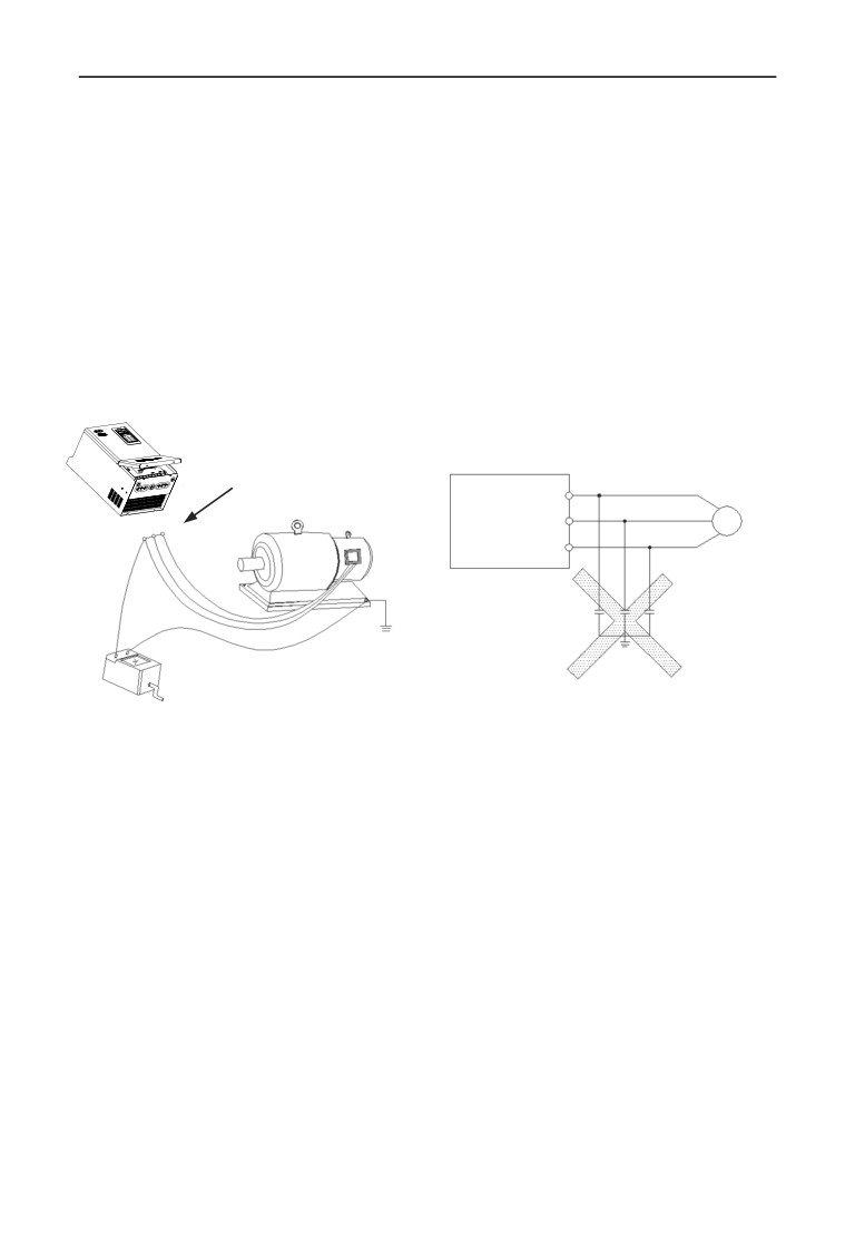
(11)Motor should do insulation check before first usage or reusage after lay aside
for long time. Checking method show as graph 1-1 below with 500V voltage type
megohm meter , insulation resistance should not smaller than 5 MΩ,otherwise
inverter maybe damaged.
(12)Forbid inverter output side to assemble capacitor to improve power factor or
anti-thunder dependent resistor etc, otherwise it may cause inverter fault trip or
component damage show as graph 1-2.
EN500/EN600
After wiring finish, short-circuit U,V,W
to measure insulation resistance
U
motor
EN500/EN600
V
M
U VW
W
Ground
Megohmmeter
Fig.1-1 motor insulation check Fig.1-2 capacitor at output side forbidden
1.4 Scraping handling notice:
Notices when handling with scrapped inverter and components:
(1) The unit: dispose the inverter as industrial waste.
(2) Electrolytic capacitor: It may cause explosion when electrolytic capacitor
under burning.
(3)Plastic: it may result in harmful and poisonous gas when plastic and rubber of
inverter burning, and safeguard preparations should be taken before burning.
4
2 Inverter type and specification
2 Inverter type and specification
2.1 Incoming inverter inspect
(1) Check if there is damage during transportation and inverter itself has damage
or fall-off parts.
(2) Check if parts presented in packing list are all ready.
(3) Please confirm nameplate data of the inverter is in line with your order
requirement.
Our product is guaranteed by strict quality system during manufacturing, packing,
transportation etc., please contact our company or local agent rapidly
if some careless omission or mistake arise, we’ll deal with it as soon as
possible.
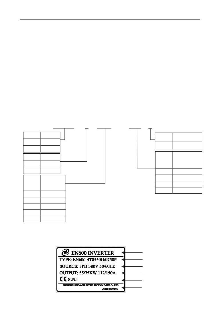
2.2 Type explanation
EN600 - 4T
0015G
/
0022P B
Code
Name
Code
accessories
EN500
Series No.
B
Inbuilt brake unit
EN600
Series No.
Dedicated fan
Code
Volt. grade
&pump
Code
motor power
2S
1 phase 220V
(KW)
4T
3 phase 380V
0015P
1.5
Constant torque
0022P
2.2
general type
Code
motor power
…
…
(KW)
6300P
630
0004
0.4
0007
0.75
…
…
5600G
560
6300G
630
Fig.2-1 Type description
2.3 Nameplate explanation
Nameplate presented as figure 2-2 with type and rating data at the bottom of
inverter right side.
Series No.
Type
Rated input vol. And freq.
Motor power and output current
Serial No.
Manufacturer and origin
Fig.2-2 Nameplate
5
2 Inverter type and specification
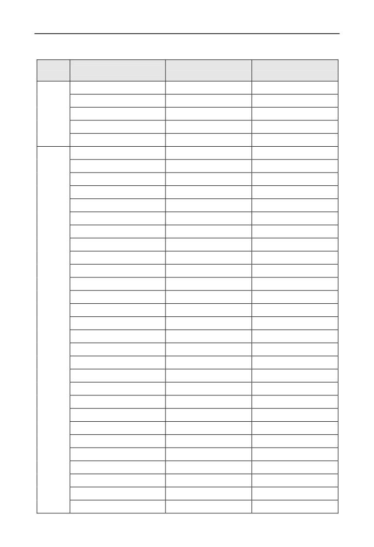
2.4 Inverter type explanation
Input
Rated output
Adaptable motor
Inverter type
Voltage
Current(A)
(KW)
EN600-2S0004
2.5
0.4
EN600-2S0007
4
0.75
1 phase
EN600-2S0015
7
1.5
220V
EN600-2S0022
10
2.2
EN600-2S0037
15
3.7
EN600-4T0007G/0015P
2.3/3.7
0.75/1.5
EN600-4T0015G/0022P
3.7/5
1.5/2.2
EN600-4T0022G/0037P
5/8.5
2.2/3.7
EN600-4T0037G
8.5
3.7
EN600-4T0055P
13
5.5
EN600-4T0055G/0075P
13/17
5.5/7.5
EN600-4T0075G/0110P
17/25
7.5/11
EN600-4T0110G/0150P
25/33
11/15
EN600-4T0150G/0185P
33/39
15/18.5
EN600-4T0185G/0220P
39/45
18.5/22
EN600-4T0220G/0300P
45/60
22/30
EN600-4T0300G/0370P
60/75
30/37
EN600-4T0370G/0450P
75/91
37/45
3 phase
EN600-4T0450G/0550P
91/112
45/55
380V
EN600-4T0550G/0750P
112/150
55/75
EN500-4T0750G/0900P
150/176
75/90
EN500-4T0900G/1100P
176/210
90/110
EN500-4T1100G/1320P
210/253
110/132
EN500-4T1320G/1600P
253/304
132/160
EN500-4T1600G/2000P
304/380
160/200
EN500-4T2000G/2200P
380/426
200/220
EN500-4T2200G/2500P
426/474
220/250
EN500-4T2500G/2800P
474/520
250/280
EN500-4T2800G/3150P
520/600
280/315
EN500-4T3150G/3550P
600/650
315/355
EN500-4T3550G/3750P
650/680
355/375
EN500-4T3750G/4000P
680/750
375/400
EN500-4T4000G/4500P
750/800
400/450
6
2 Inverter type and specification
EN500-4T4500G/5000P
800/870
450/500
EN500-4T5000G/5600P
870/940
500/560
EN500-4T5600G/6300P
940/1100
560/630
EN500-4T6300G
1100
630
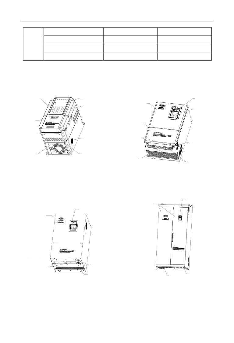
2.5 Appearance and parts name explanation
2.5.1 EN600 Appearance and parts name explanation
LED
digital tube
LED
digital tube
Up cover plate
Upcover plate
Operation keyboard
Operation keyboard
Down cover plate
Down cover plate
Control cable inlet
Nameplate
Control cable
inlet
Nameplate
Input & output
Fan hole
power cable
Fan hole
Input & output
inlet
power cable inlet
Fig.2-3 EN600 Parts name sketch
2.5.2 EN500 Appearance and parts name explanation
Operation keyboard
Cover door
Operation keyboard
Up cover plate
Input & output
power cable inlet
Control cable inlet
Input & output
power cable
Bottom installation
inlet
Control cable inlet
Bottom installation hole
hole
Fig.2-4 EN500 Parts name sketch
7
2 Inverter type and specification
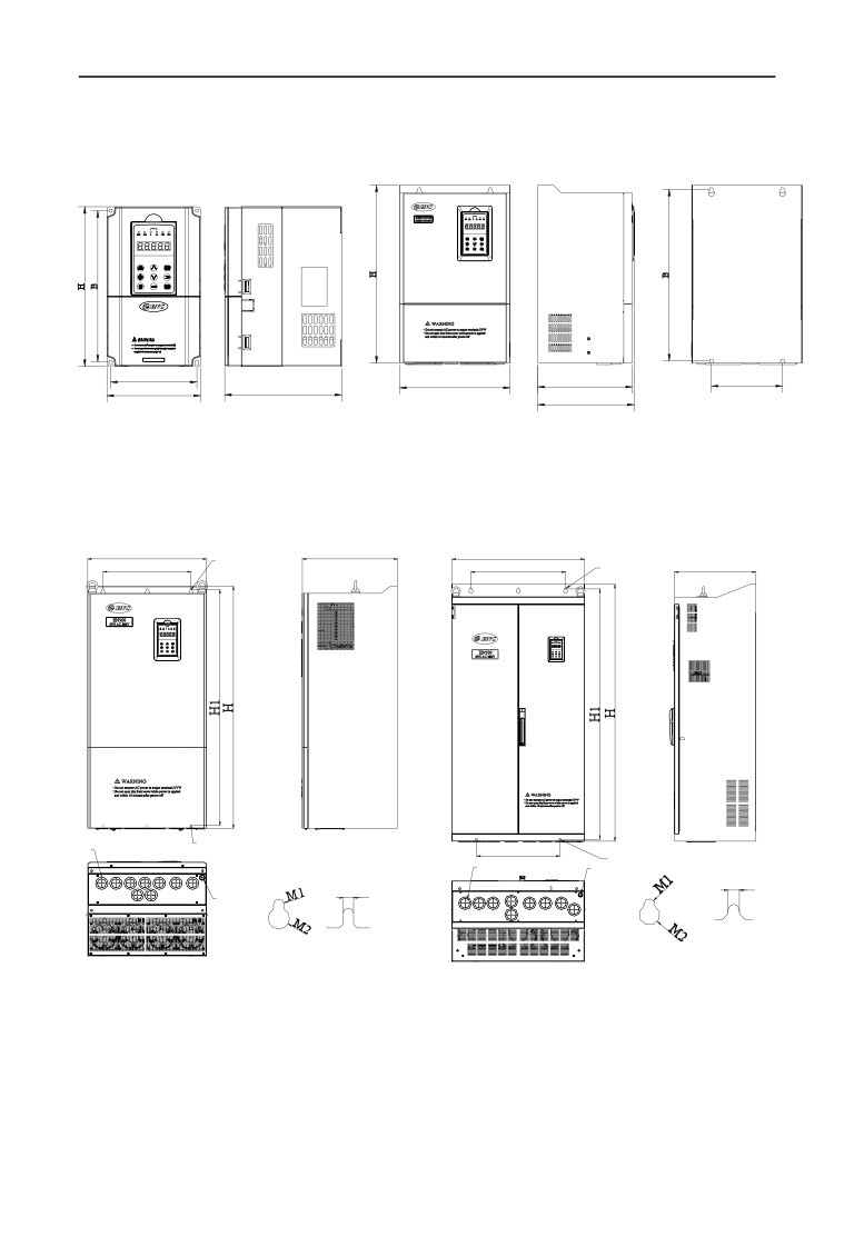
2.6 Outer size
A
W
D
A
W
D
D1
Fig.a
Fig.b
W
D
W
W1
Adetail
W1
A
detail
D
N1
Bdetail
W2
B
detail
N1
N2
M1
M1
N2
A
detail
B
detail
Adetail
B
detail
Fig.c
Fig.d
8
2 Inverter type and specification
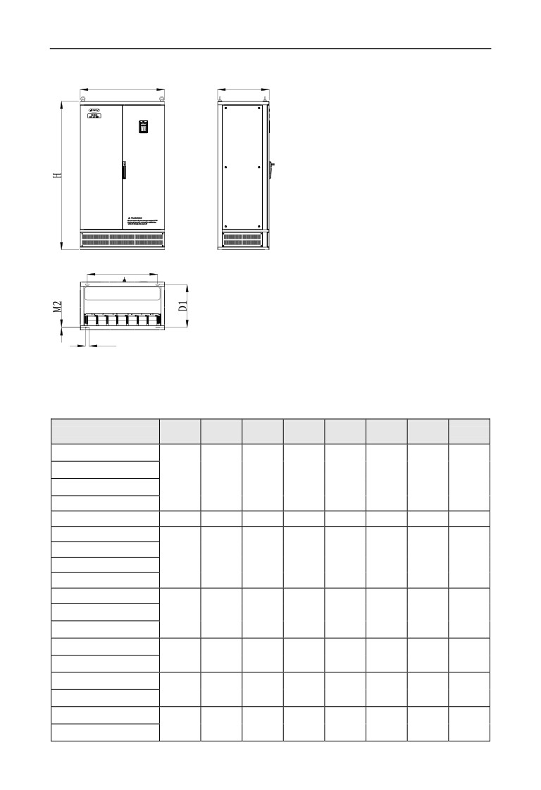
W
D
W1
M1
Fig.e
Fig.2-5 outer dimension
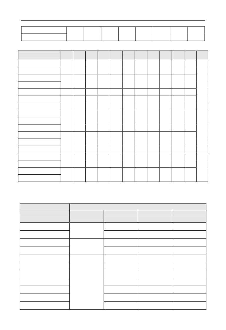
Table 2-1
EN600 mounting size
A
B
W
H
D
D1
Fix Hole
Inverter type
Fig. No.
(mm)
(mm)
(mm)
(mm)
(mm)
(mm)
(mm)
EN600-2S0004
EN600-2S0007
104
186
115
200
151
-
5
Fig.a
EN600-2S0015
EN600-2S0022
EN600-2S0037
129
227
140
240
175
-
5
Fig.a
EN600-4T0007G/0015P
EN600-4T0015G/0022P
104
186
115
200
151
-
5
Fig.a
EN600-4T0022G/0037P
EN600-4T0037G
EN600-4T0055P
EN600-4T0055G/0075P
129
227
140
240
175
-
5
Fig.a
EN600-4T0075G/0110P
EN600-4T0110G/0150P
165
281
180
304
189
-
6
Fig.a
EN600-4T0150G/0185P
EN600-4T0185G/0220P
180
382
250
398
210
214
9
Fig.b
EN600-4T0220G/0300P
EN600-4T0300G/0370P
180
434
280
450
240
244
9
Fig.b
EN600-4T0370G/0450P
9
2 Inverter type and specification
EN600-4T0450G/0550P
190
504.5
290
530
250
254
9
Fig.b
EN600-4T0550G/0750P
Table 2-2
EN500 mounting size
H
H1
W
W1
W2
D
D1
N1
N2
M1
M2
Fig.
Inverter type
(mm)
(mm)
(mm)
(mm)
(mm)
(mm)
(mm)
(mm)
(mm)
(mm)
(mm)
No.
EN500-4T0750G/0900P
570
546
340
237
-
320
-
-
-
ĭ12
ĭ18
EN500-4T0900G/1100P
EN500-4T1100G/1320P
650
628
400
297
-
340
-
-
-
ĭ12
ĭ18
EN500-4T1320G/1600P
Fig.c
EN500-4T1600G/2000P
980
953
480
370
-
400
-
ĭ38
ĭ19
ĭ9
ĭ18
EN500-4T2000G/2200P
1030
1003
500
370
-
400
-
ĭ38
ĭ19
ĭ9
ĭ18
EN500-4T2200G/2500P
EN500-4T2500G/2800P
EN500-4T2800G/3150P
1368
1322
700
500
440
430
-
ĭ52
ĭ19
ĭ12
ĭ22
EN500-4T3150G/3550P
Fig.d
EN500-4T3550G/3750P
OB
EN500-4T3750G/4000P
1518
1483
700
500
500
430
-
ĭ19
ĭ12
ĭ22
77*47
EN500-4T4000G/4500P
EN500-4T4500G/5000P
1650
-
850
700
-
550
490
-
-
40
ĭ13
EN500-4T5000G/5600P
Fig.e
EN500-4T5600G/6300P
1700
-
900
750
-
550
490
-
-
40
ĭ13
EN500-4T6300G
2.7 EN500 optional base
2.7.1 EN500 inverter and base selection table
Base model
Type
base with Input
Base with
base with DC
Standard base
reactor
output reactor
reactor
EN500-4T0750G/0900P
SP-BS-0750-LI
SP-BS-0900-LO
SP-BS-0750-LD
SP-BS-0900
EN500-4T0900G/1100P
SP-BS-0900-LI
SP-BS-0900-LO
-
EN500-4T1100G/1320P
SP-BS-1100-LI
SP-BS-1100-LO
-
SP-BS-1320
EN500-4T1320G/1600P
SP-BS-1320-LI
SP-BS-1320-LO
-
EN500-4T1600G/2000P
SP-BS-1600
SP-BS-1600-LI
SP-BS-1600-LO
-
EN500-4T2000G/2200P
SP-BS-2000-LI
SP-BS-2000-LO
-
SP-BS-2200
EN500-4T2200G/2500P
SP-BS-2200-LI
SP-BS-2200-LO
-
EN500-4T2500G/2800P
SP-BS-4000
SP-BS-2500-LI
SP-BS-2500-LO
-
EN500-4T2800G/3150P
SP-BS-2800-LI
SP-BS-2800-LO
-
EN500-4T3150G/3550P
SP-BS-3150-LI
SP-BS-3150-LO
-
EN500-4T3550G/3750P
SP-BS-4000-LI
SP-BS-4000-LO
-
10
2 Inverter type and specification
EN500-4T3750G/4000P
SP-BS-4000-LI
SP-BS-4000-LO
-
EN500-4T4000G/4500P
SP-BS-4000-LI
SP-BS-4000-LO
-
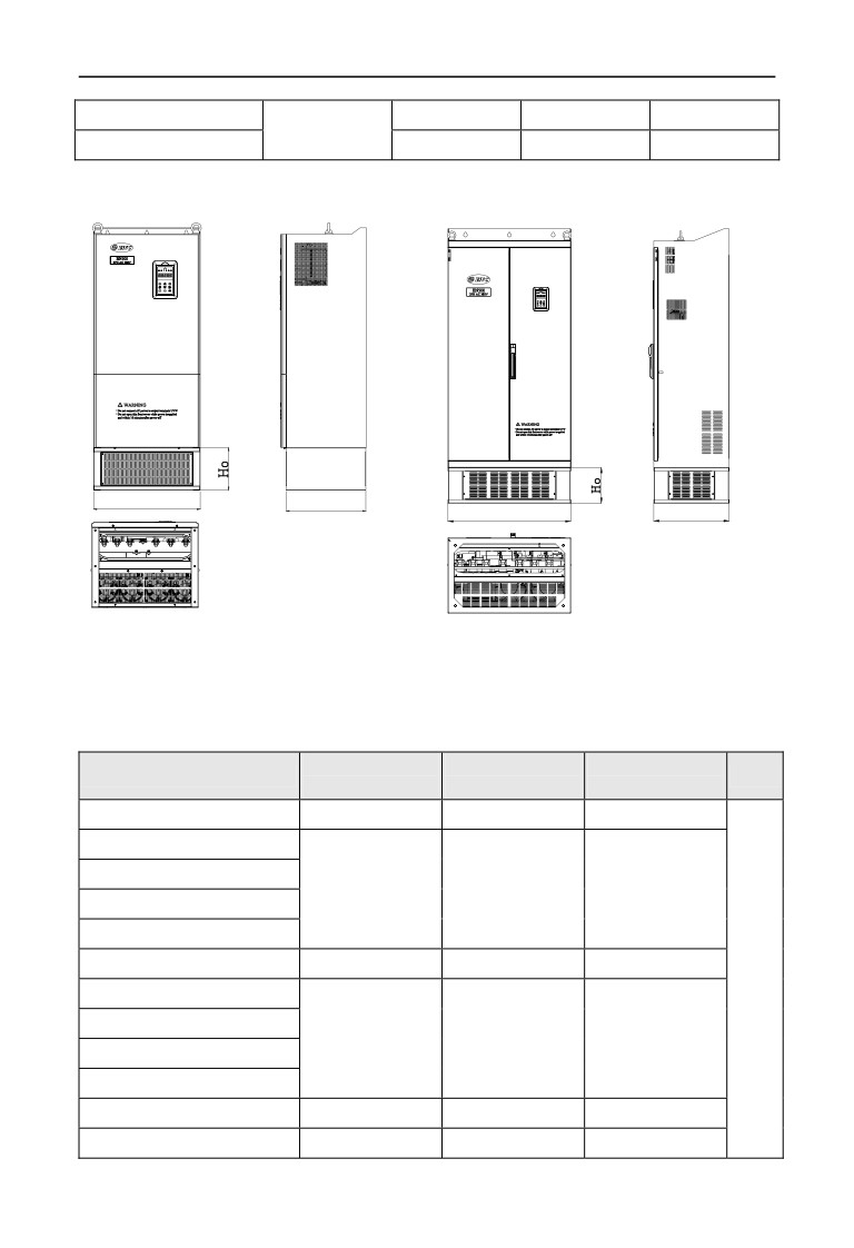
2.7.2 Base outer dimension
W
D1
W
D1
Fig.a
Fig.b
Fig.2-6 base dimension
Table 2-3 base size
W
D1
Ho
Base model
Fig.
(mm)
(mm)
(mm)
SP-BS-0900
340
300
180
Fig.a
SP-BS-0750-LI
SP-BS-0750-LD
340
300
350
SP-BS-0900-LI
SP-BS-0900-LO
SP-BS-1320
400
320
180
SP-BS-1100-LI
SP-BS-1100-LO
400
320
380
SP-BS-1320-LI
SP-BS-1320-LO
SP-BS-1600
480
380
180
SP-BS-1600-LI
480
380
400
11
2 Inverter type and specification
SP-BS-1600-LO
SP-BS-2200
500
380
200
SP-BS-2000-LI
SP-BS-2000-LO
500
380
400
SP-BS-2200-LI
SP-BS-2200-LO
SP-BS-4000
700
430
204
SP-BS-2500-LI
SP-BS-2500-LO
SP-BS-2800-LI
700
430
400
SP-BS-2800-LO
Fig.b
SP-BS-3150-LI
SP-BS-3150-LO
SP-BS-4000-LI
700
430
450
SP-BS-4000-LO
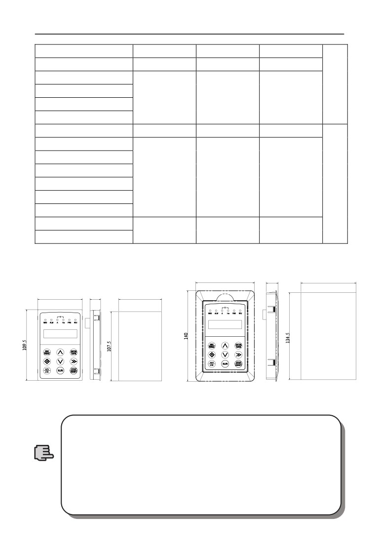
2.8 Outer size of keypad and its fixing box(unit:mm)
88
17.9
82.8
67
16
64.5
Fig.2-7 Mounting size of keypad
Fig.2-8 Hole size of keypad
1. EN-LCD2 long-distance keypad outer lead, do not support
keypad holder installed, only keypad installed support, mounting
size refer to Fig.2-7.
2. Except EN-LCD2 long-distance keypad, when other keypad
Note
outer lead, user can adjust the hole size under actual situation on
keypad or keypad holder; thickness of install board between 1.0~
1.5mm is suggested.
3. When installed with keypad holder, it need to buy extra.
12
2 Inverter type and specification
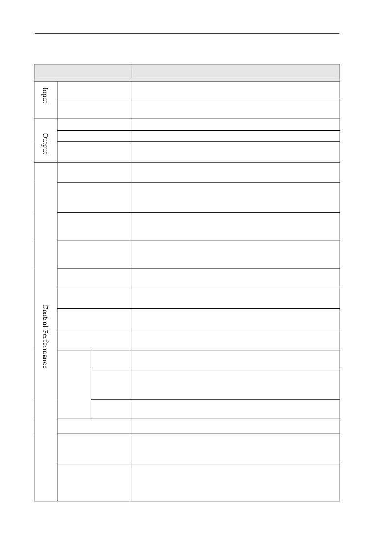
2.9 Product technic index and spec
Item
Item description
1 phase 220V Grade:1 phase 220V, 50Hz/60Hz
Rating volt., frequency
3 phase 380V Grade:3 phase 380V, 50Hz/60Hz
1 phase 220V Grade:200~260V
Allowed volt. range
3 phase 380V Grade:320~460V
Voltage
0~380V
Frequency
0~600Hz
G type:150% of rated current for 1 minute;
Over loading capacity
P type:120% of rated current for 1 minute.
vector control, PG vector control, open-loop V/F control, torque
Control mode
control, PG torque control
±0.5% rated synchronous speed(vector control);
Velocity control
±0.1% rated synchronous speed(PG vector control);
precision
±1% rated synchronous speed(V/F control);
1:2000(PG vector control)
Speed regulation range
1:100(vector control);
1:50(V/F control);
1.0Hz:150% rated torque(V/F control);
Start-up torque
0.5Hz:150% rated torque (vector control);
0Hz:180% rated torque(PG vector control);
±0.3% rated synchronous speed(vector control);
Speed fluctuation
±0.1% rated synchronous speed(PG vector control);
Torque control
±10% rated torque(vector control,torque control);
precision
±5% rated torque(PG vector control,PG torque control).
20ms(vector control);
Torque response
10ms(PG vector control);
Digital setting:max. frequency×±0.01%;Analog setting:max.
Frequency precision
frequency×±0.5%
Analog
0.1% of max. frequency
setting
Digital
Freq.
setting
0.01Hz
resolution
precision
Exterior
0.1% of max. frequency
impulse
Torque boost
Automatic torque boost;manual torque boost 0.1~12.0%
V/F curve(volt.
Setting rated frequency at the range of 5~650Hz,by choosing
Frequency
constant torque, degressive torque
1, degressive torque
2,
characteristic)
degressive torque 3, self-defined V/F total 5 kinds of curve.
Two modes:straight line acceleration and deceleration; S curve
Acceleration
acceleration and deceleration;
15 kinds of acceleration and
Deceleration curve
deceleration time,time unit (0.01s, 0.1s, 1s) for option ,max. time
for 1000 minutes.
13

2 Inverter type and specification
EN600 3 phase 15KW & under power range with inbuilt brake
unit,only add brake resistor between(+)and PB.
Power
18.5KW & up power range is possible to add brake unit between
consumption
(+)and(-)outside; or extra connect brake unit with adding brake
brake
brake
resistor between(+)and PB.
EN500 series can connect brake unit between(+)and(-)outside.
Start, stop action for option, action frequency
0~15Hz,action
DC brake
current 0~100% of rated current,action time 0~30.0s
Jog frequency range:0Hz~up limit frequency;jog acceleration
jog
and deceleration time 0.1~6000.0 seconds for setting.
Realized by inbuilt PLC or control terminal; with 15 section speed,
Multi-section speed
each section speed with separately acceleration and deceleration
run
time; with inbuilt PLC can achieve reserve when power down.
Inbuilt PID controller
Convenient to make closed-loop control system
Automatic energy
Optimize V/F curve automatically to achieve power saving run
saving run
according to the load status.
Automatic voltage
Automatically keep output voltage constant, when the power grid
regulate(AVR)
voltage fluctuation
Automatic current
Current limited automatically under run mode in avoid of inverter
limiting
over-current frequently to trip.
Modulate carrier wave automatically according to the load
carrier modulation
characteristic.
Speed tracking restart
Make rotating motor smoothly start without shocking
running command
Keypad specified, control terminal specified, communication
specified channel
specified can switch through various means.
Main & auxiliary specified to a realize one main adjusting and one
Running frequency
fine control. Digital specified, analog specified, pulse specified,
specified channel
pulse width specified, communication specified and others, which
can be switched by many means at any time.
Run command channel and frequency specified channel can bind
Binding function
together randomly and switch synchronously
Channel 8 for universal digital input, max. Frequency
1KHz,
Digital input channel
channel 1 can be used as pulse input channel, max. Input 50KHz,
which can be expanded to channel 14 .
Channel 2 for analog input channel, AI1 can choose 4~20mA or
0~10V output,AI2 is differential input channel,4~20mA or
Analog input channel
-10~10V for option,which can be expanded to channel 4 analog
input.
0.1 ~ 20KHz pulse square signal output to achieve setting
Pulse output channel
frequency, output frequency and other physical quantity output.
Channel 2 for analog signal output, AO1 can choose 4~20mA or
0~10V,AO2 can choose 4~20mA or 0~10Vto achieve setting
Analog output channel
frequency, output frequency and other physical quantity output,
which can be expanded to channel 4 analog output.
14
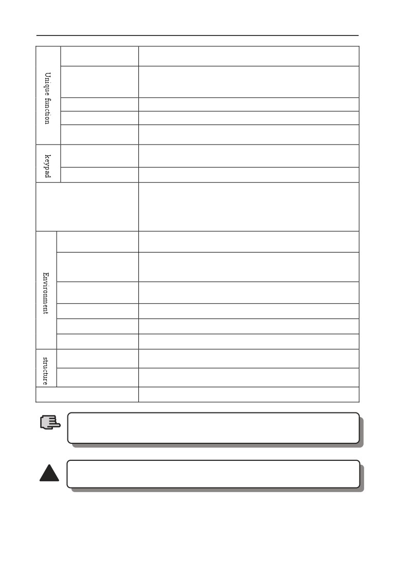
2 Inverter type and specification
Limit inverter over current to the greatest point, and make it run
Rapid current limit
more stably
Suitable for working site where need one button to control inverter
Monopulse control
start and stop, first press to start, then press to stop, and that cycle
repeats. Its very simple and reliable.
Fixed length control
Realize fixed length control
Timing control
Timing control function: setting time range 0.1Min ~ 6500.0Min
Five group virtual input & output IO can realize simply logical
Virtual terminal
control
The parameters as setting frequency, output frequency, output
Keypad display
voltage, output current can be displayed
Button Locked
Lock all or part of the buttons
Motor power on Shot circuit test, input & output phase loss
protection, over-current protection, over voltage protection, under
Protection function
voltage protection, over heat protection, overload protection, under
load protection, relay absorption protection, terminal protection
and no stop protection under power off.
Indoor, not bare to sunlight, no dust, no corrosive gas, no
Application site
flammable gas, no vapor, no water drop or salt etc.
Under 1000 meter.(above 1000 meter require to reduce volume to
Altitude
use, output current reduce about 10% of rated currenvolt per 1000
meter high)
Environment
-10℃~+40℃ ( environment temperature between 40℃~50℃,
temperature
need to reduce volume or strengthen heat sink )
Environment humidity
Smaller than 95%RH,no drop condenses
Vibration
Smaller than 5.9 M/S²(0.6g)
Storage temperature
-40℃~+70℃
Protection grade
IP20
Cooling mode
Forced air cooling and natural
Installation mode
Wall hanging and cabinet installation
To get a perfect usage performance of the inverter, Please check and
select right type according to this chapter before wiring.
Note
It is necessary to select right type, otherwise it may cause motor
!
abnormal run or inverter damage.
15
3 Installation and wiring
3 Installation and wiring
3.1 Installation ambient
3.1.1 The demands for installation ambient
(1) Installed in drafty indoor place,the ambient temperature should be within
-10ºC~40ºC,it needs external compulsory heat sink or reduce the volume if
temperature is over than 40ºC; when temperature under -10℃, please preheat
inverter first.
(2) Avoid installing in places with direct sunlight, much dust, floating fiber and
metal powder.
(3) Don’t install in place with corrosive, explosive gas.
(4) The humidity should be smaller than 95%RH,without condensation water.
(5) Installed in place of plane fixing vibration smaller than 5.9m/s²(0.6g).
(6) Keep away from electromagnetic disturbance source and other electronic
apparatus sensible to electromagnetic disturbance.
3.1.2 Installation direction and space
(1) Normally the inverter should be mounted vertically, horizontal mounting will
seriously affect heat dissipation and the inverter must be used in lower volume.
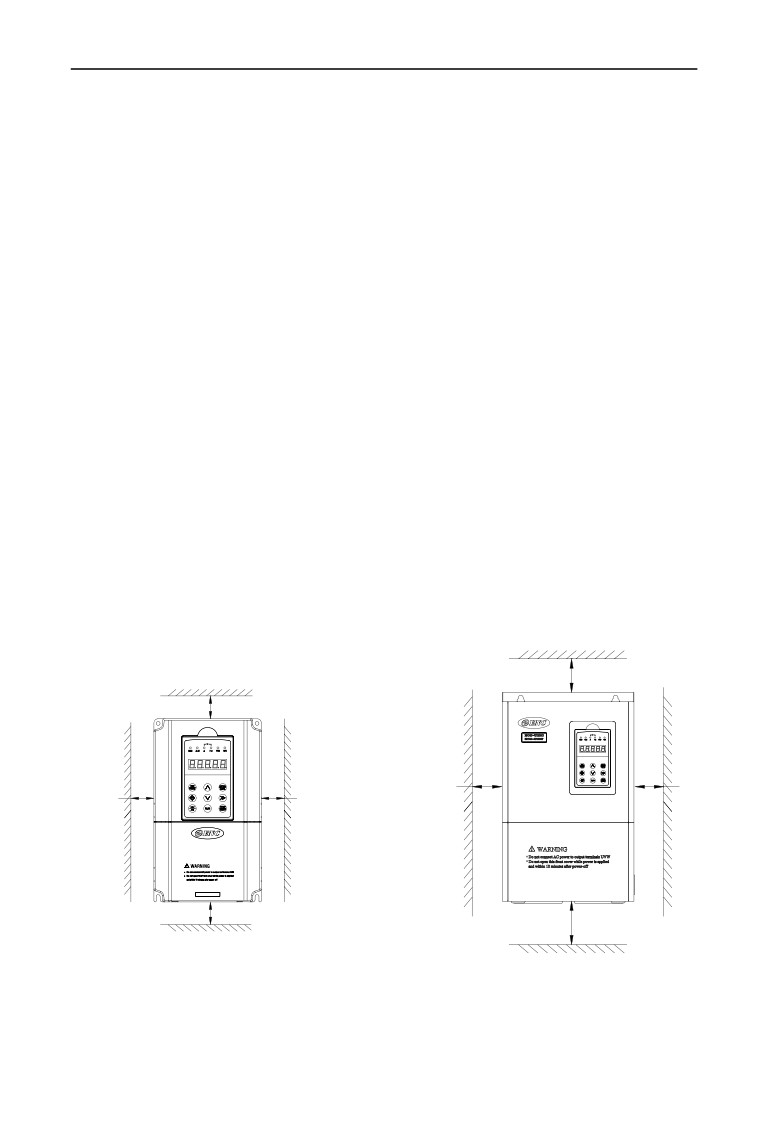
(2) Demand for minimum mounting space and distance,please see Fig.3-1.
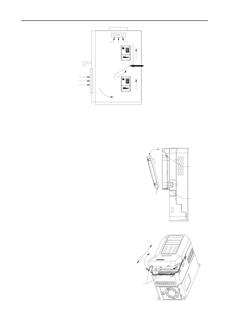
(3) When installing multiple inverters up and down, leading divider must be
applied between them, see fig. 3-2.
Fan exhaust
200mmabove
Fan exhaust
110mm
above
100mm
100mm
50mm
50mm
above
above
above
above
110mm
a
above
200mmabove
a:15KW & down power
b:18.5KW & up power
Fig.3-1 mounting space
16
3 Installation and wiring
Leading divider
Fig.3-2 mounting of multiple inverters
3.2 Parts disassembly and installation
3.2.1 Keyboard disassembly and installation
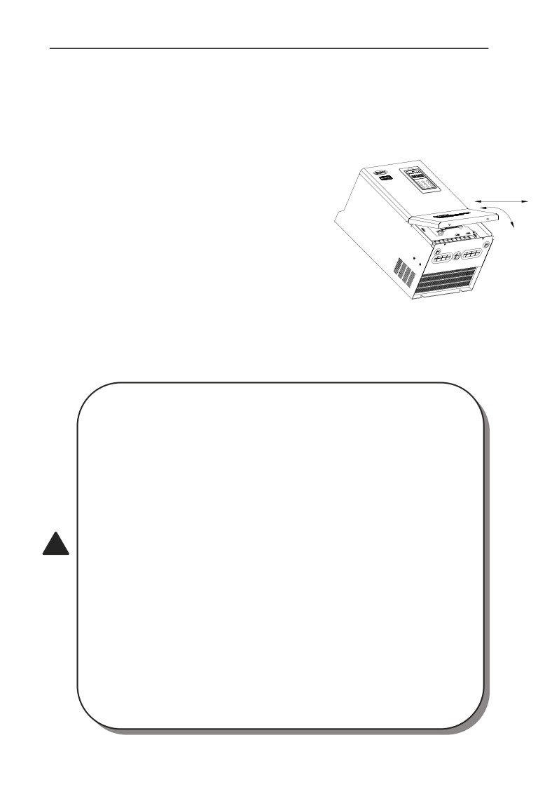
(1) Disassembly
Let the forefinger press finger inlet on the keypad,
Assemble
depress fixing flexible plate on the top lightly,
hook
draw it outward, then you can disassemble
the keypad.
(2) Assembly
Assemble
hook mouth
First interface the fixed hook of on the bottom
hook
of keyboard with the keyboard installation claw
of inverter, then press the fixed shrapnel on the top
of keyboard to push it assemble well properly
(keyboard assemble well when sounding of crisp),
show as Fig.3-3.
Fig.3-3 Keypad assembly
3.2.2 Cover disassembly and installation
3.2.2.1 Cover disassembly and installation
(1) Disassembly
Located the thumbs to the side bayonet,
the ring fingers on the joint of the up and
down cover, with thumbs press inside and
pull upside at the same time until the bayonet
snap
joint
open between cover and whole case, then pull
back cover to make it off the inverter.
Fig.3-4 metal cover disassemble and assembly
17
3 Installation and wiring
(2) Assembly
1) tilt cover at 5~10 degree;
2) interface installation claw with hook on the top of inverter, press down heavily till
cover bayonet enter into the holes of two side completely, show as Fig.3-4.
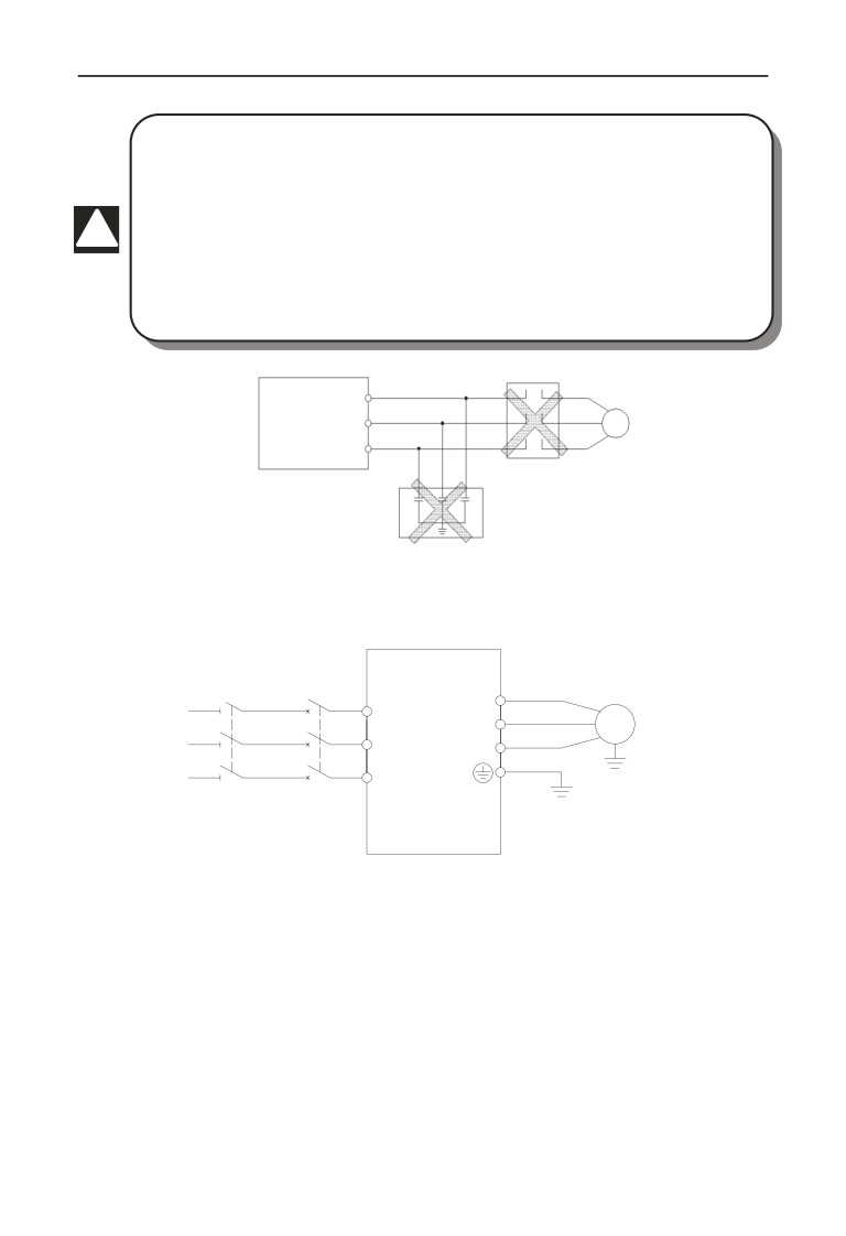
3.2.2.2 Metal cover disassembly and installation:
(1) Disassembly
First take off 2 screws at the side of the cover
and move it a bit outward horizontally, then tilt
it at 15 degree and draw it outward at the direction
shown in right figure, now you can take the cover off.
(2) Assembly
First put down the cover in parallel with unit body
and make it just locked at two sides of the inverter,
secondly force it ahead and make fixing part on its
top inserted into fixing slot of unit body, at last screw
the cover and finish assembly for the cover.
Fig.3-5 metal cover disassemble
As shown in Fig.3-5
and assembly
3.3 Wiring notice points
⑴Assure power be cut off completely for above 10 minutes before
wiring, otherwise there is danger of getting electric shock.
⑵ Forbid connecting power wire to output U, V, W of the inverter.
⑶ If there is current leakage inside inverter, inverter and motor must be
earth grounding for safety assurance, please refer to clause 8 in Chapter
3.4.1 for grounding wiring.
⑷ Before shipment compression resistance test of the inverter is
Passed, so users should not conduct compression resistance test again.
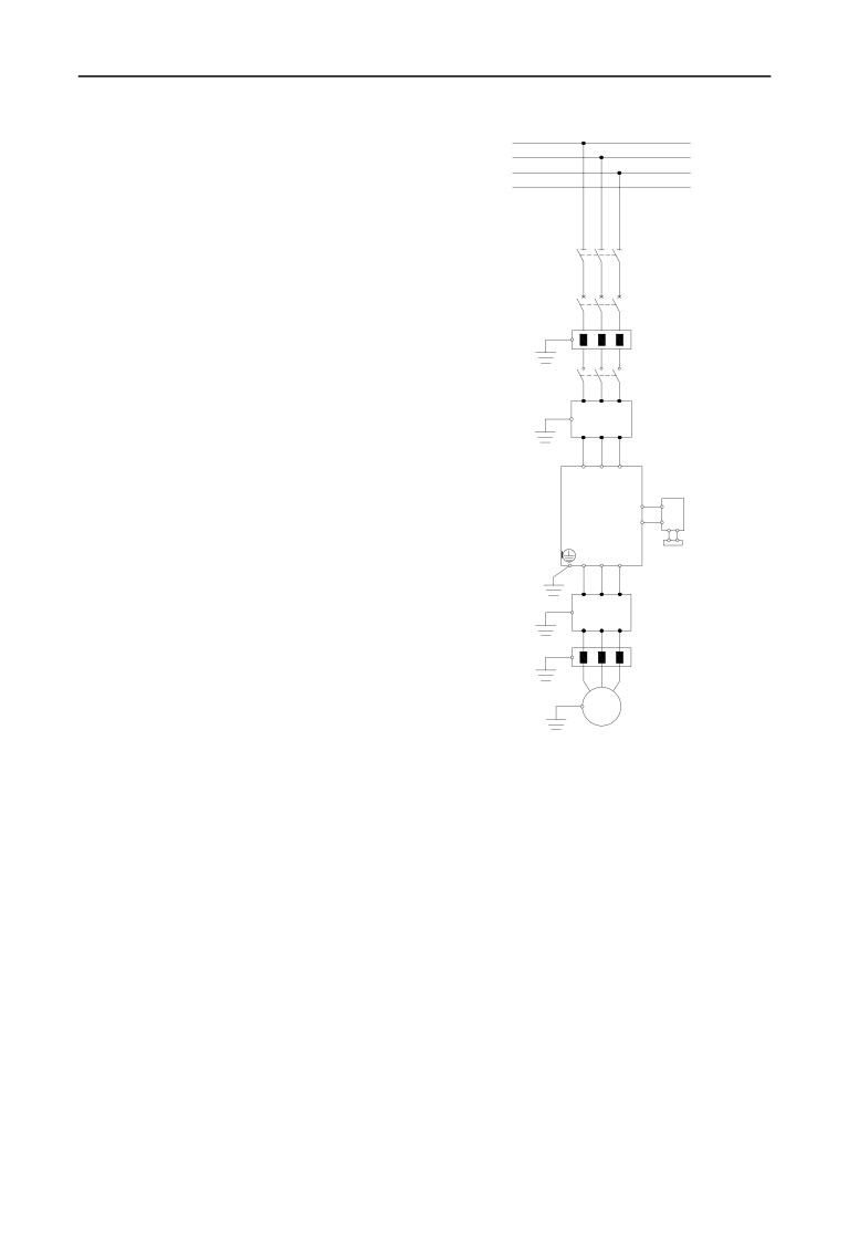
⑸ Do not add absorbing capacitor or other resistance-capacitor
!
absorbing device between inverter and motor; also do not add
electromagnetic contact. If contactor and other switch component
needed to add, please make sure inverter suspended without output,
show as Fig.3-6
⑹ To provide inverter over-current protection in output side and
convenient maintenance under power off, it should be connected to
power source through air switch and contactor.
⑺ Control signal wire should select multicore stranded wire or
shielding wire. One end of the shielding layer hang in the air, and the
other end connect to inverter earth grounding terminal, connection wire
shorter than 20m.
18
3 Installation and wiring
⑴Before wiring, assure power supply is cut off completely for 10
minutes and all LED or LCD indicator light extinguished.
⑵ Before inverter internal wiring, confirm that DC volt. Between main
loop end P+ and P- fall down to below DC36V.
⑶ Wiring can only be done by professional person trained and qualified.
!
⑷ Before power on, check if voltage grade of the inverter is in line with
that of power supply volt., otherwise will cause personnel injured and
device damaged.
U
inverter
V
M
W
Fig.3-6 Forbid to use contactor and absorbing capacitor
3.4 Main loop terminal wiring
Air switch
contactor
(breaker
)
EN500/
U
3
R
EN600
V
M
phase
S
AC
W
power
T
Fig.3-7 main loop simple wiring
To keep user power grid safety, please choose proper air switch, breaker, wiring at
power input side,parameter recommended show as Table 3-1(Remark:wire
must choose PVC insulation copper conductor).
19
3 Installation and wiring
Table 3-1 parameter recommended for air switch(breaker), contactor and
wire selection
Air switch
Input
Output
Control
Contactor
Type
or breaker
power wire
motor cable
signal wire
(A)
(A)
mm2
mm2
mm2
EN600-2S0004
6
9
0.75
0.75
0.5
EN600-2S0007
10
12
0.75
0.75
0.5
EN600-2S0015
16
18
1.5
1.5
0.5
EN600-2S0022
16
18
1.5
1.5
0.5
EN600-2S0037
20
25
2.5
2.5
0.75
EN600-4T0007G/0015P
6
9
0.75
0.75
0.5
EN600-4T0015G/0022P
10
12
0.75
0.75
0.5
EN600-4T0022G/0037P
16
18
1.5
1.5
0.5
EN600-4T0037G
16
18
1.5
1.5
0.5
EN600-4T0055P
20
25
2.5
2.5
0.75
EN600-4T0055G/0075P
20
25
2.5
2.5
0.75
EN600-4T0075G/0110P
25
25
4.0
4.0
0.75
EN600-4T0110G/0150P
32
32
6.0
6.0
0.75
EN600-4T0150G/0185P
40
40
6.0
6.0
0.75
EN600-4T0185G/0220P
50
50
10
10
1.0
EN600-4T0220G/0300P
50
50
10
10
1.0
EN600-4T0300G/0370P
63
63
16
16
1.0
EN600-4T0370G/0450P
80
80
25
25
1.0
EN600-4T0450G/0550P
100
115
35
35
1.0
EN600-4T0550G/0750P
125
125
50
50
1.0
EN500-4T0750G/0900P
250
160
70
70
1.5
EN500-4T0900G/1100P
250
160
95
95
1.5
EN500-4T1100G/1320P
350
350
120
120
1.5
EN500-4T1320G/1600P
400
400
120
120
1.5
EN500-4T1600G/2000P
500
500
150
150
1.5
EN500-4T2000G/2200P
630
630
185
185
1.5
EN500-4T2200G/2500P
700
700
240
240
1.5
EN500-4T2500G/2800P
800
800
120*2
120*2
1.5
EN500-4T2800G/3150P
800
800
120*2
120*2
1.5
EN500-4T3150G/3550P
1000
1000
150*2
150*2
1.5
EN500-4T3550G/3750P
1000
1000
185*2
185*2
1.5
EN500-4T3750G/4000P
1250
1250
240*2
240*2
1.5
EN500-4T4000G/4500P
1250
1250
240*2
240*2
1.5
EN500-4T4500G/5000P
1250
1250
270*2
270*2
1.5
EN500-4T5000G/5600P
1600
1600
270*2
270*2
1.5
EN500-4T5600G/6300P
1600
1600
300*2
300*2
1.5
EN500-4T6300G
2000
2000
300*2
300*2
1.5
20
3 Installation and wiring
3.4.1 Connection between inverter and fitting parts
(1) Breaking device like isolation
R
S
Switch must assemble between power
T
N
source and inverter to keep persona
safety under repairing and
inverter requirement for compulsory power off.
Isolation switch
(2) There must be over-current
Protection breaker or fuse in inverter
Breaker or fuse
power supply circuit to avoid failure
expanding because of the second device failure.
Ac input reactor( In option)
(3) AC input reactor
Contactor
When high harmonics between inverter
and power supply is strong which cannot
Input EMI filter( In option)
meet system requirement or input side
power factor need to improve, ac input reactor
R
S
T
can be added.
EN500/EN600
(4) Contactor is used to power supply only,
(+)
Brake unit( In option)
(-)
do not use it to control inverter start and stop.
(5) Input side EMI filter
U V W
hoosing optionally EMI filter to
restrain high frequency transduction
Input EMI filter( In option)
interference and radio-frequency
interference from inverter power line.
Ac output reactor( In option)
(6) Output side EMI filter
Choosing optionally EMI filter to
M
restrain radio-frequency Interference
and wire leakage current from inverter
Fig.3-8 connection of inverter and
output side.
fitting parts
(7) AC output reactor
Installing AC output reactor is suggested
to avoid motor insulation damage, oversize current leakage and inverter frequent
protection when connecting wire between inverter and motor exceeds 50m.
(8) Safety earth ground wire
Inverter and motor must be earth ground connection, connection wire should
select as shorter and thicker as above 3.5mm² multicore copper wire, and earth
grounding resistance smaller than10ȍ.
21
3 Installation and wiring
3.4.2 Main loop terminal wiring
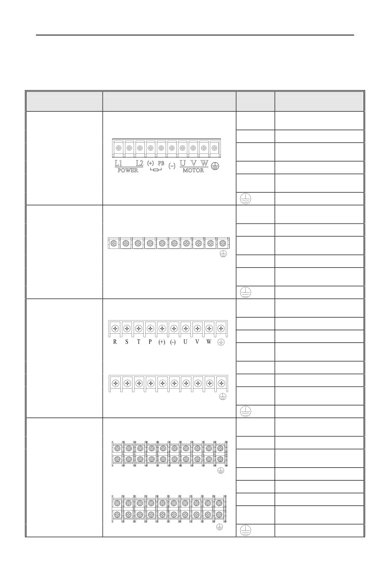
(1)Main loop input output terminal show as table 3-2, 3-3.
Table 3-2 EN600 main loop input output terminal description
Terminal
Adapted type
Main loop terminal
Function description
name
1 phase AC input terminal,
L1、L2
connect power source
(+)
DC volt. Positive terminal
EN600-2S0004
External connect to brake
PB
~
resistor reverse terminal
EN600-2S0037
(-)
DC volt. Negative terminal
3 phase AC output terminal,
U、V、W
connect to motor
Grounding terminal
3 phase AC input terminal,
R、S、T
connect power source
(+)
DC volt. Positive terminal
EN600-4T0007G/0015P
External connect to brake
PB
~
R S T (+)
PB
(-)
U
V
W
resistor reverse terminal
EN600-4T0150G/0185P
(-)
DC volt. Negative terminal
3 phase AC output terminal,
U、V、W
connect to motor
Grounding terminal
3 phase AC input terminal,
R、S、T
Terminal 1:
connect power source
P、(+)
External connect to DC reactor
(+)
DC volt. Positive terminal
External connect to brake
EN600-4T0185G/0220P
PB
resistor reverse terminal
EN600-4T0220G/0300P
Terminal 2:
(-)
DC volt. Negative terminal
(+)、(-)External connect brake unit
3 phase AC output terminal,
R S T (+)
PB
(-)
U
V
W
U、V、W
connect to motor
Grounding terminal
3 phase AC input terminal,
R、S、T
Terminal 1:
connect power source
P、(+)
External connect to DC reactor
External connect to brake
PB
resistor reverse terminal
EN600-4T0300G/0370P
R S T P
(+)
(-)
U
V
W
(+)
DC volt. Positive terminal
EN600-4T0370G/0450P
Terminal 2:
(-)
DC volt. Negative terminal
(+)、(-)External connect brake unit
3 phase AC output terminal,
U、V、W
connect to motor
R S T PB (+)
(-)
U
V
W
Grounding terminal
22
3 Installation and wiring
3 phase AC input terminal,
Terminal 1:
R、S、T
connect power source
P、(+)
External connect to DC reactor
External connect to brake
PB
resistor reverse terminal
R S T P
(+)
(-) U V W
EN600-4T0450G/0550P
(+)
DC volt. Positive terminal
EN600-4T0550G/0750P
Terminal 2:
(-)
DC volt. Negative terminal
(+)、(-)External connect brake unit
3 phase AC output terminal,
U、V、W
connect to motor
R S T PB (+)
(-) U V W
Grounding terminal
Note:
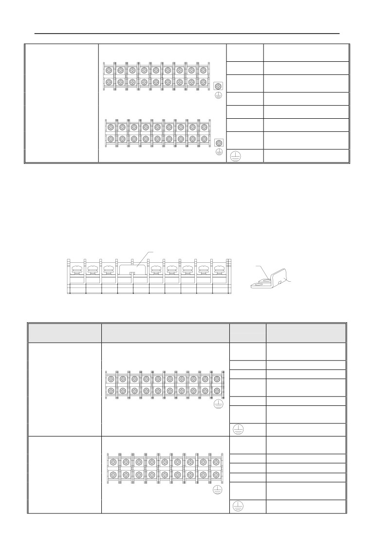
① EN600-4T0185G/0220P~EN600-4T0550G/0750P there are two kinds
of sort order for main loop terminal, terminal 2 remove “P”,add “PB” terminal.
② EN600-4T0185G/0220P~EN600-4T0550G/0750P(terminal 1)short circuit
diagram of copper bar assembly on main loop terminal
edgefold assembly in up direction for short
circuit copper bar
Short circuit copper bar
edgefold in up
direction
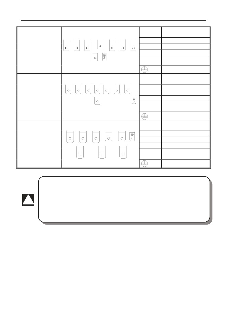
Table 3-3 EN500 main loop input output terminal description
Terminal
Adapted type
Main loop terminal
Function description
name
3 phase AC input terminal,
R、S、T
connect power source
(+)
DC volt. Positive terminal
(-)
DC volt. Negative terminal
External connect to DC
EN500-4T0750G/0900P
P、(+)
reactor
R S T
P
(+)
V W
(+)、(-)External connect brake unit
3 phase AC output terminal,
U、V、W
connect to motor
Grounding terminal
3 phase AC input terminal,
R、S、T
connect power source
(+)
DC volt. Positive terminal
EN500-4T0900G/1100P
(-)
DC volt. Negative terminal
~
(+)、(-)External connect brake unit
EN500-4T1320G/1600P
R S T (+)(-)U V W
3 phase AC output terminal,
U、V、W
connect to motor
Grounding terminal
23
3 Installation and wiring
3 phase AC input terminal,
R、S、T
connect power source
(+)
DC volt. Positive terminal
R
S
T
(+)
U
V
W
EN500-4T1600G/2000P
(-)
DC volt. Negative terminal
~
(+)、(-)External connect brake unit
EN500-4T2200G/2500P
(-)
3 phase AC output terminal,
U、V、W
connect to motor
Grounding terminal
3 phase AC input terminal,
R、S、T
connect power source
R
S
T
(+)
U
V
W
(+)
DC volt. Positive terminal
EN500-4T2500G/2800P
(-)
DC volt. Negative terminal
~
(-)
(+)、(-)External connect brake unit
EN500-4T4000G/4500P
3 phase AC output terminal,
U、V、W
connect to motor
Grounding terminal
3 phase AC input terminal,
R、S、T
connect power source
R
S
T
(+)
(-)
(+)
DC volt. Positive terminal
EN500-4T4500G/5000P
(-)
DC volt. Negative terminal
~
(+)、(-)External connect brake unit
EN500-4T6300G
U
V
W
3 phase AC output terminal,
U、V、W
connect to motor
Grounding terminal
1. The wiring of main loop must connect right according to the
description above. Wrong wiring will cause device damage and personal
injury.
2. Short circuit copper bar assembly for 18.5KW and up power (terminal
!
1) for EN600 must be edgefold in up direction,or it will cause device
damage and personal injury in the reverse direction.
24

3 Installation and wiring
3.5 Basic running wiring diagram
External
External connect
Brake resistance fitting part
Brake unit
itting part
(L1 220V AC)
(L2 220V AC)
EN500/ EN600
multi-function input
internal optocoupler isolation input
X terminal active, electric level
support high level and low level
Relay load
Lower level valid---short circuit
slice connect PW and +24V,
external wiring show as solid line
high level valid---short circuit slice
connect PW and COM, external
Frequency meter
wiring show as dotted line
pulse
Used as hi-speed pulse input
Analog output type
switch
terminal DI
voltmeter
switch
amperemeter
Short
when external power source used,
circuit
remove the short circuit slice
slice
Program relay output(F09.04)
Open
Open
Close
close
Analog input type SW1 switch AI1 valid
Com-
mon
Analog input type SW2 switch
AI2 valid
Voltage input
Current input
Twisted-pair cable
Voltage input
Communication port
Current input
Must set parameter F00.20 when SW2 switch
Fig.3-9 basic wiring diagram
Note:When connect to external DC reactor, it need to remove the short-circuit
copper bar between P and(+).
3.6 Control loop collocation and wiring
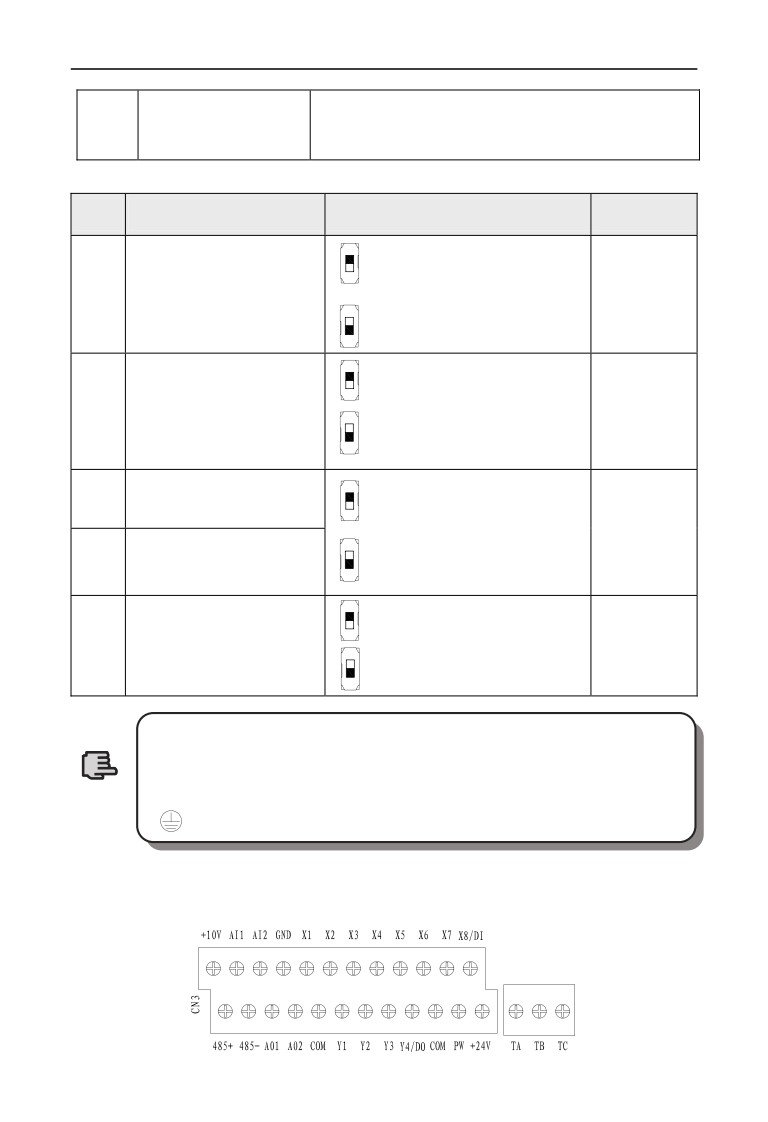
3.6.1 Relative location and function for control board terminal and slide
switch:
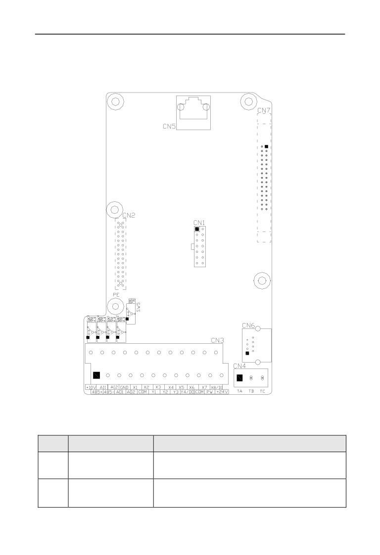
Control board terminal and slide switch location show as Fig 3-10.
The terminal CN1 and CN7 are used by the manufacturers,CN2 is extended
25
3 Installation and wiring
interface,CN5 is for keypad,The CN3,CN4 and CN6 for users can be seen in
table 3-4,The setting description and function of slide switch check table3-5.
Please read the following descriptions carefully before using inverter.
Fig.3-10 sketch map of CPU board
Table 3-4 function description of terminal provided for user
No.
Function
Description
Input and output control
To use when inverter run under external terminal control ,
CN3
of external terminal
refer to 3.6.2
TA-TC is normal open contact;TB-TC is normal closed
CN4
Signal output of relay
contact,refer to 3.6.2
26
3 Installation and wiring
CrystalRS485communicat
To use when inverter through
485 communication can
CN6
ion interface
achieve cascade connection and other control, refer to 3.6.2
Table 3-5 Slide switch function description for users
No.
Function
Setting
Default value
V:F00.20 be XXX0
AI1 Analog input signal
0~+10V voltage signal input
F00.20 be 0000
SW1
selection
0~+10V
I:F00.20 be XXX1
4~20mA current signal input
V: F00.20 be XX0X,
AI2 Analog input signal
-10V~+10V voltage signal input
F00.20 be 0000
SW2
selection
-10V~+10V
I:F00.20 be XX1X,
4~20mA current signal input
AO1 Analog output signal
SW3
V:F00.21 be XX00
selection
0~+10V voltage signal output
F00.21 be 0000
0~+10V
AO2 Analog output signal
SW4
I:F00.21 be XX11
selection
4~20mA current signal output
EMI inhibition for selection
:earth grounding
SW5
suspending
terminal
:suspending
(1) In the graphic of slide switch, black square means switch
slidable location.
(2) Only when heavy interfering exist on working site, it’s
Note
suggested to put EMI dial switch to earth grounding location, and
should connect to the earth.
3.6.2 Descriptions for control board terminal
⑴ CN3 and CN4 terminal layout as following
CN4
27
3 Installation and wiring
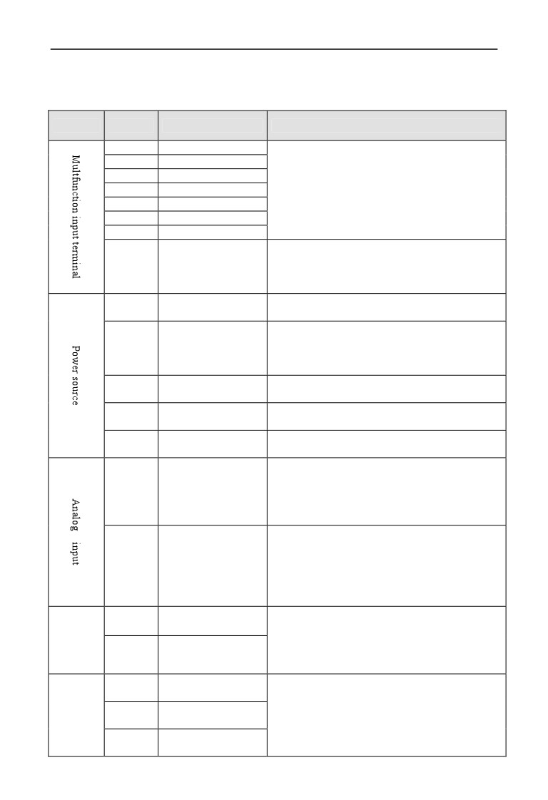
⑵ CN3 and CN4 terminal function description show as Table 3-6
Table 3-6 function table for control board terminal
Type
Symbol
Description
Terminal Function and specification
X1
Multifunction input 1
X2
Multifunction input 2
Input voltage range:15~30V;
X3
Multifunction input 3
Opto coupler isolation, Compatible with bipolar
X4
Multifunction input 4
input;
X5
Multifunction input 5
Input impedance:4.7Kȍ
X6
Multifunction input 6
max input frequency:1KHz
X7
Multifunction input 7
Except for X1~X7 function,it can be used as
Multifunction input 8/
hi-speed pulse input.
X8/DI
high-speed
pulse
Input impedance:2.2Kȍ
input
max input frequency:50KHz
Provide +24V power to external device(24±4V)
+24V
+24V power source
Max output current:200mA
factory default connect to +24V;when use external
External power source
signal to drive X terminal,it need to connect to
PW
input
external power source and cut off with
+24V
power terminal.
Provide +10Vpower to external device(10±0.5V)
+10V
+10V power source
Max output current:50mA
Reference ground for digital signal and
+24V
COM
Common interface
power
Reference ground for analog signal and
+10V
GND
Common interface
power
Input range:DC 0V~10V/4~20mA,selected by
SW1 dial switch on control board.
AI1
Analog input 1
Input impedance:voltage input at 20Kȍ; current
input at 250ȍ.
resolution:1/4000
Input range:DC-10V~10V/4~20mA,selected by
the second figure of F00.20 and SW2 dial switch
on control board.
AI2
Analog input 2
Input impedance:voltage input at 20Kȍ;current
input at 250ȍ.
resolution:1/2000
Voltage or current output is selected by SW3
AO1
Analog output 1
(AO1)and SW4(AO2) dial switch on control
Analog
board.
output
AO2
Analog output 2
Output voltage range:0~10V
Output current range:4~20mA
Multi-
Open circuit collector
Y1
function
output 1
Opto coupler isolation output , unipolar Open
output
Open circuit collector
circuit collector output
Y2
terminal
output 2
Max voltage output:30V
Open circuit collector
Max current output:50mA
Y3
output 3
28
3 Installation and wiring
Function code F00.22 to select terminal output
Open circuit collector
mode
output 4/
When Open circuit collector output, with the same
Y4/DO
High-speed impulse
spec as terminal Y.
output
When High-speed impulse
outputˈthe max frequency is 20KHz.
Normal closed
TB—TC
Contact capacity˖AC250V/2A˄cosφ=1˅
Relay
terminal
AC250V/1A˄cosφ=0.4˅
output
Normal open
TA—TC
DC30V/1A
terminal
Communi
485+
485 differential signal positive terminal
485 differential
cation
signal interface
interface
485-
485 differential signal negative terminal
CN2
retain
Auxiliary
StandardRS485
interface
CN6
communication
Twisted-pair cable or shield wire to connect
interface
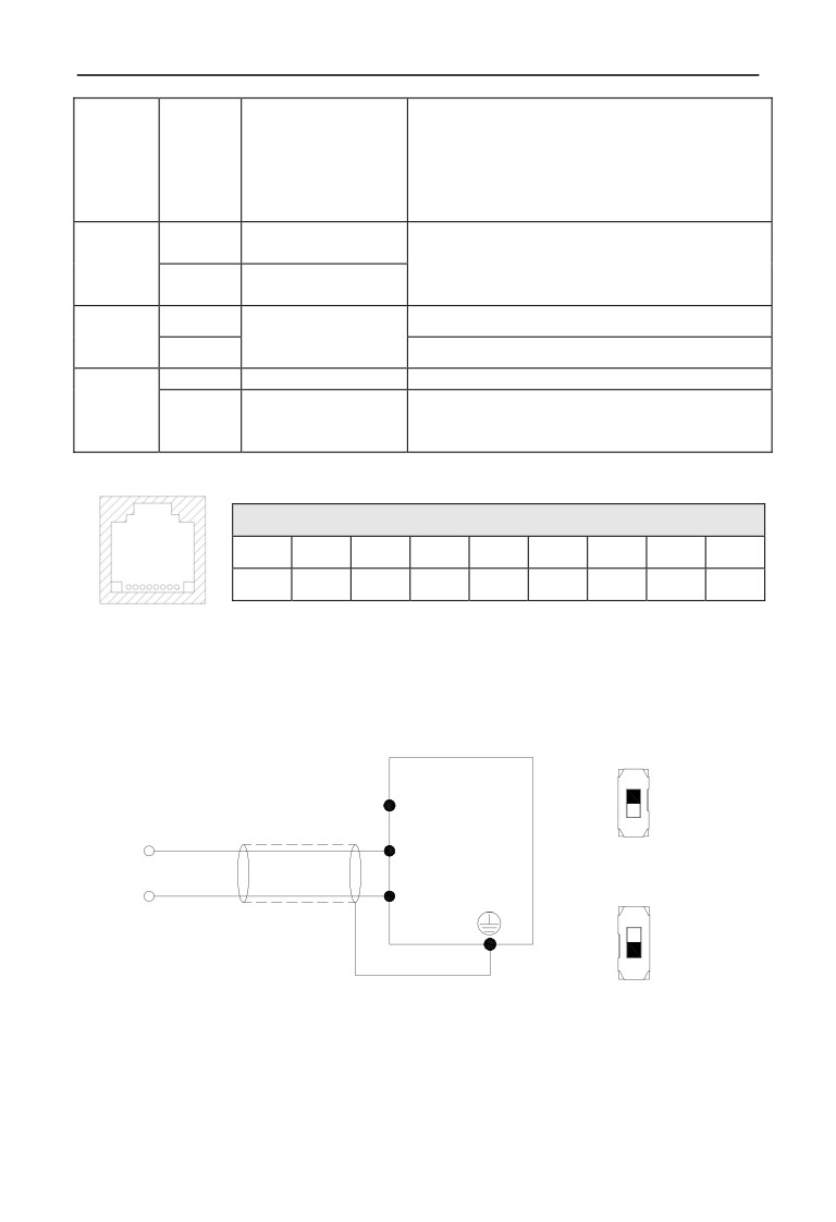
⑶ RS485 crystal outlet CN6 layout as following
RS485 terminal CN6 layout
No.
1
2
3
4
5
6
7
8
12345 678
Name
485+
485-
-
-
-
-
-
-
3.6.3 Analog input&output terminal wiring
(1) AI1 receive analog voltage or current signal single-ended input, switch
through SW1, wire as below˖
AI1 voltage input
9
SW1
EN500/
̚
9
EN600
$,
0̚10V
or ̚ P$
*1'
AI1 current input
Shield cable near-end earth
grounding
SW1
4̚20mA
Fig.3-11 AI1 terminal wiring diagram
3 Installation and wiring
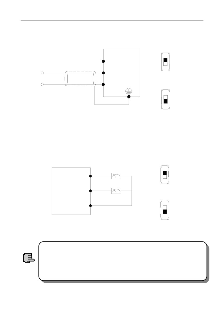
(2) AI2 receive analog voltage or current signal single-ended input, switch through
SW2ˈand should match it with exact second figure of F00.20 setting, wire as
below˖
AI2 voltage input
9
SW2
EN500/
EN600
9̚
9
$,
or ̚ P$
-10̚10V
*1'
AI2 current input
Shield cable near-end
earth grounding
SW2
4̚20mA
Fig.3-12 AI2 terminal wiring diagram
(3) AO1,AO2 terminal can connect to external analog meter, which can indicate
several physical quantityˈit can select analog voltage or current signal outputˈand
switch through SW3 and SW4ˈwire as below˖
AO1,AO2 voltage output
Analog meter
SW3,SW4
$2
Analog meter
0̚10V
EN500/EN600
$2
AO1,AO2 current output
*1'
SW3,SW4
4̚20mA
Fig.3-13 AO1,AO2 terminal wiring diagram
(1) Under analog input mode, filter capacitor or common mode
choke can be installed between AI1 and GND or AI2 and GND.
(2) Analog input and output signal can be interfered easily by
ambient environment, it need use shield cable for connection and
Note
earth grounding well as short as possible.
3.6.4 Digital input terminal wiring
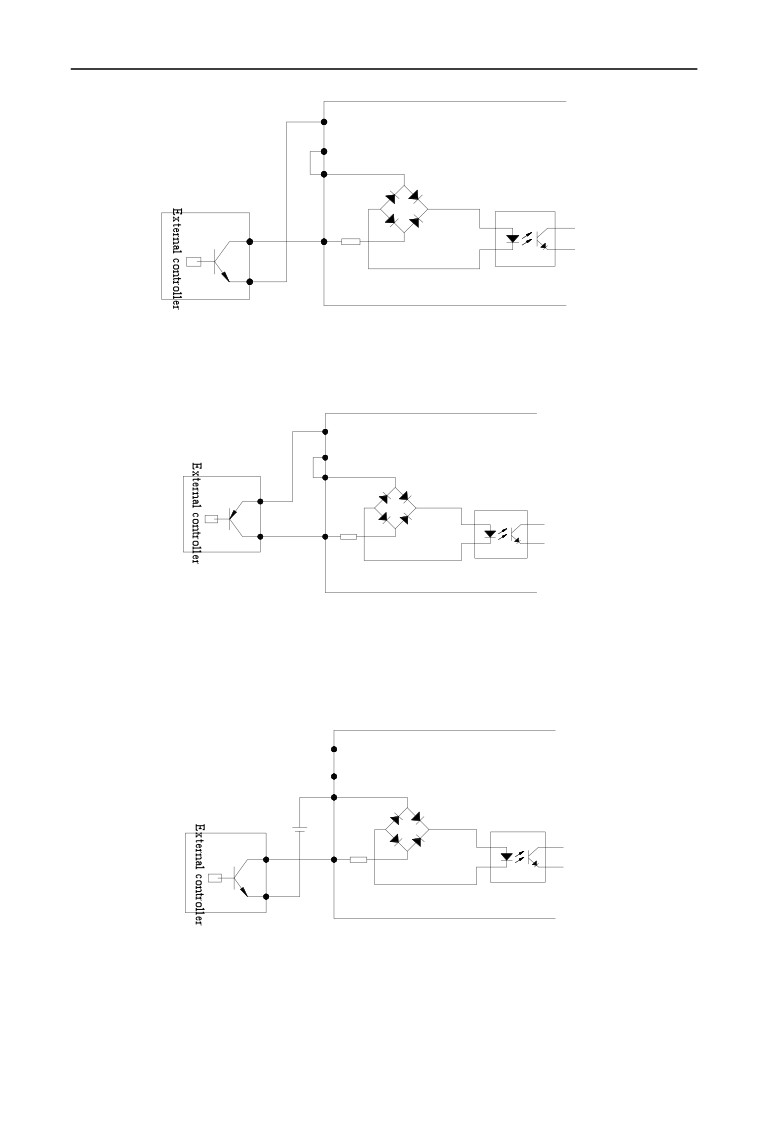
⑴ To use inverter inbuilt +24V power supply, and NPN source type external
controller connection mode.
3 Installation and wiring
COM
EN500/EN600
+24V
PW
Signal wire
X1
R
COM
Fig.3-14 inbuilt 24V source type connection mode
⑵ To use inverter inbuilt +24V power supply, and PNP drain type external
controller connection mode.
+24V
COM
EN500/EN600
PW
VCC
X1
COM
R
Fig.3-15 inbuilt 24V drain type connection mode
⑶ To use external DC 15~30V power supply,and NPN source type external
controller connection mode.(remove the short circuit slice between PW and
+24V).
COM
EN500/EN600
+24V
PW
+
-
Signal wire
X1
R
COM
Fig.3-16 external power supply source type connection mode
31
3 Installation and wiring
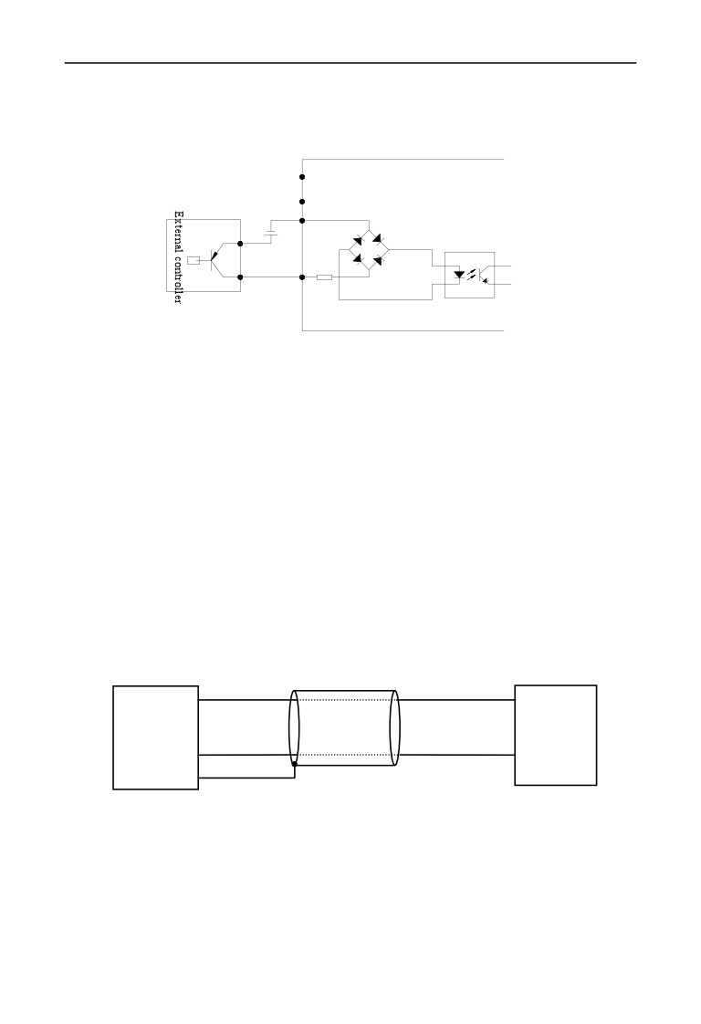
⑷ To use external DC 15~30V power supply,and PNP drain type external
controller connection mode.(remove the short circuit slice between PW and
+24V)
+24V
COM
EN500/EN600
PW
-
VCC
+
X1
COM
R
Fig.3-17 External power supply drain type connection mode
3.6.5 Communication terminal wiring
EN500/EN600 inverter provide RS485 serial communication interface to user.
The following wire connection can make up of single-main single-sub control
system or single-main multi-sub control system. To use host computer softwa(PC
or PLC controller)can realize real time monitoring and operation to inverter,and
to achieve complicated run control like long-distance control, high degree
automation. It can also use a host inverter and the other slave inverter to make up
of the cascade or synchronous control inverter network.
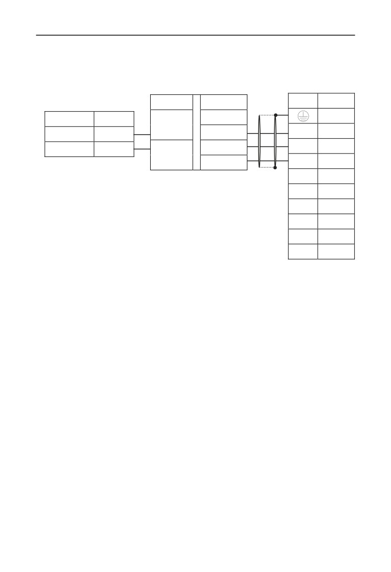
⑴ Inverter RS485 interface and other device with RS485 interface wire connection
show as following
EN500/
A(485+)
A(485+)
Device with
RS485
EN600
B(485-)
B(485-)
or
RS485
EN500/EN600
Fig.3-18 Communication terminal wiring
32
3 Installation and wiring
⑵ Inverter RS485 interface and host computer (device with RS232 interface)
connection:
RS232/RS485 transverter
Host computer
name
description
Shield cable
signal
Pin No.
EN500/EN600 inverter
+5V
shell
description
name
B
TXD
RXD
2
Signal negative
B
TXD
3
Signal positive
A
RXD
A
GND
GND
5
DTR
4
DSR
6
RI
9
CD
1
RTS
7
CTS
8
Fig.3-19 RS485 communication wiring
33
4 EMC(Electromagnetic Compatibility)Explanation
4 EMC(Electromagnetic compatibility)explanation
Because of inverter working principal resulting in electromagnetic noise, and to
avoid or reduce inverter interference to ambient environment, this chapter
introduce installation means to restrain interference from aspect of interference
restrain, field wiring, system earth grounding, leakage current and power filter
usage. Inverter will have good electromagnetic compatibility under general
industrial environment, when user install the inverter according to this chapter.
4.1 Noise interference restraining
Inverter interference generating for run may have effect to nearby electronic
device and the effect depend on the inverter installation surrounding
electromagnetic environment and the restrain interference ability of the device.
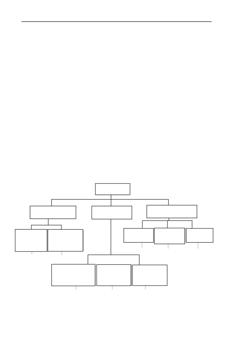
4.1.1 Interference noise type
Becuase of inverter working principle, there are mainly
3 kinds of noise
interference source::
⑴ circuit conduction interference;
⑵ space emission interference;
⑶ electromagnetic induction interference;
Interference Type
Circuit conduction
Space emission
Electromagnetic
interference
interference
induction interference
Leak current
Power wire high
Input wire
Inverter power
Output wire
earth grounding
harmonic current
induction
component
induction
wire loop
conduction
induction
interference
interference
route
⑥
route
⑦
route
⑧
route
①
route
②
Inverter main circuit
Motor wire
Power wire
switch and switch
U,V,W radio
R,S,T radio
power radio
inteference
interference
interference
route
③
route
④
route
⑤
Fig.4-1 interference noise type
34
//////////////////////////////////////////