ENC EN500 / EN600 series inverter (ver. 2.0). Service manual - page 4
7 Detailed function specification
F03.01
Torque boost mode
Range: 0, 1
0
0: Manual boost. Torque boost voltage is totally decided by parameter
F03.02, whose feature is that the boost voltage is fixed, but magnetic saturation of
the motor is occurs often to the light-load.
Boost voltage =
F03.02
×motor rated voltage
100
1: Auto torque boost. Torque boost voltage changes when the stator current
of the motor changes, the greater the stator current is, magnetic saturation boost
voltage is.
F03.02
Inverter output current
Boost voltage =
×motor rated voltage×
100
2×inverter rated current
Depend on
F03.02
Torque boost
Range: 0.0~12.0%
type
Torque boost cut-off
Range:0.0~100.0%
F03.03
100.0%
frequency
(motor rated frequency )
Improving inverter low torque characteristic, the output voltage can be
compensated
Motor rated
Motor rated
volt.
volt.
Boost
Boost
volt.
Volt.
Cut-off Motor
Cut-off
Motor
Freq.
rated freq.
Freq.
rated freq.
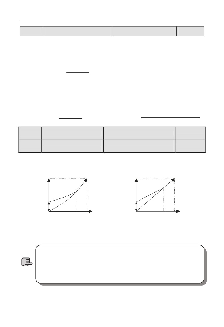
a Degression torque curve Torque boost
b Constant torque curve Torque boost
Fig. 7-8 Torque boost
1.F03.02 for increasing torque setting to this parameter can cause
motor heating or over current protection.
2.When driving synchronous machine ,User is advised to adopt
Note
manual torque boost and adjust V/F curve according to motor
parameter and usage occasion when driving synchronous motor.
115
7 Detailed function specification
Range: 0.00~V/F frequency
F03.04
V/F frequency value 0
10.00Hz
value1
Range:0.00~V/F voltage
F03.05
V/F voltage value 0
20.00%
value1
Range: V/F frequency value
F03.06
V/F frequency value1
20.00Hz
0~V/F frequency value2
Range: V/F voltage value0~
F03.07
V/F voltage value1
40.00%
V/F voltage value2
Range: V/F frequency value1~
F03.08
V/F frequency value2
25.00Hz
V/F frequency value3
Range: V/F voltage value1~
F03.09
V/F voltage value2
50.00%
V/F voltage value3
Range: V/F frequency value2~
F03.10
V/F frequency value3
40.00Hz
upper limiting frequency
Range: V/F voltage value2~
F03.11
V/F voltage value3
80.00%
100.00%(motor rated voltage)
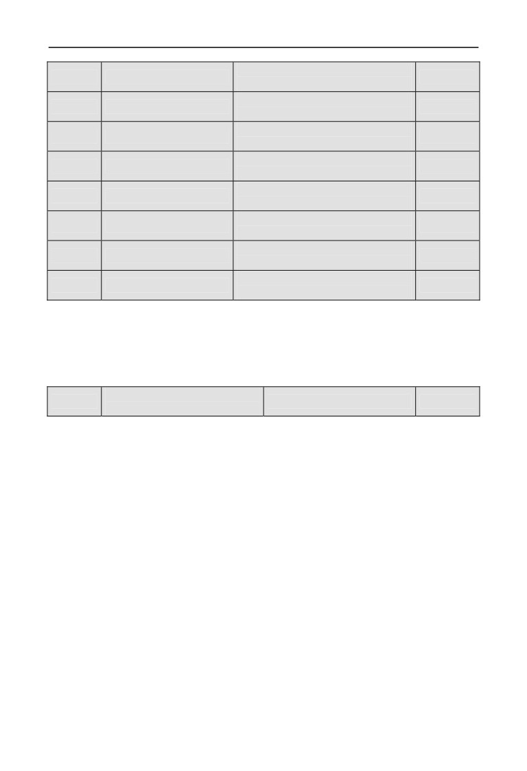
F03.04 ~ F03.11 defines multi-step V/F curve. Note that 4 voltage points and
frequency points relationship shall be satisfied: V0<V1<V2<V3, F0<F1<F2<F3,
for details, please refer to Fig. 7-8b.
If the voltage at low frequency is set too high, motor overheat or even over
burning may cause, over current protection may occur to the inverter.
V/F oscillation suppression
F03.12
Range: 0~255
10
factor
Under V/F control, this parameter can be set properly to prevent motor vibration
of the motor. When the inverter operates at low frequency without load, the
greater the motor power is, the greater the vibration of motor will be. This
parameter can be increased to restrain the vibration of motor. When carrier freq. is
smaller, this parameter can be adjusted lower to reduce vibration.
116
7 Detailed function specification
7.5 Auxiliary running parameter group: F04
Range: 0.00Hz~upper limiting
F04.00
Jump freq. 1
0.00Hz
frequency
Range: 0.00Hz~upper limiting
F04.01
Jump freq. 1 range
0.00Hz
frequency
Range: 0.00Hz~upper limiting
F04.02
Jump freq. 2
0.00Hz
frequency
Range: 0.00Hz~upper limiting
F04.03
Jump freq. 2 range
0.00Hz
frequency
Range: 0.00Hz~upper limiting
F04.04
Jump freq. 3
0.00Hz
frequency
Range: 0.00Hz~upper limiting
F04.05
Jump freq. 3 range
0.00Hz
frequency
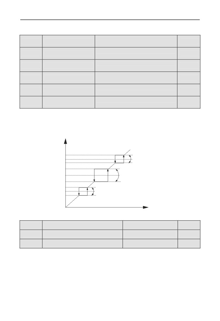
F04.00 ~ F04.05 is set to keep inverter’s output frequency away from resonance
frequency of mechanical load. Inverter setting frequency can jump around some
frequency point according to mode as shown in Fig. 7-9, 3 jumping ranges can be
defined at most.
Set freq. after adjustment
Jump freq. 3
Jump range3
Jump freq. 2
Jump range2
Jump freq. 1
Jump range1
Output freq.
Fig. 7-9 Jump freq. and range
F04.06
Slip freq. gain
Range: 0.0~300.0%
0.0%
F04.07
Slip compensation limit
Range: 0.0~250.0%
100.0%
F04.08
Slip compensation time constant
Range: 0.1~25.0s
2.0s
This function can adjust output frequency properly as the load varies to
compensate slip frequency of the asynchronous motor dynamically, so that control
motor speed is in constant value. If acting with automatic torque boost function,
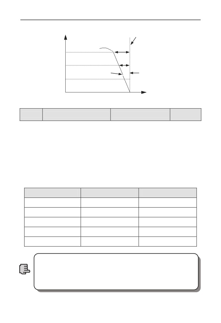
better low speed moment characteristic can be obtained. As shown in Fig.7-10.
Slip compensation range = Slip compensation limit (F04.06)× Rated slip .
Rated slip = F15.03 ×60 / Np - F15.04.
Np is motor polarity.
117
7 Detailed function specification
Slip compensation is 100%
Output current
150%
100%
Before slip compensation
After slip compensation
50%
Motor revolving speed
Fig. 7-10 Slip freq. Compensation
Depend on
F04.09
Carrier frequency
Range: 0.5~16.0K
type
Carrier freq. mainly affects motor noise and heat loss when running. Relationship
among carrier freq, motor noise, and leak current is as follows:
When carrier freq. goes up (Ĺ), the motor noise is reduced (Ļ), leakage current of
the motor is increased (Ĺ), and the interference is increased (Ĺ);
When carrier freq. goes down (Ļ), the motor noise is increased (Ĺ), leakage current
of the motor is decreased (Ļ), and the interference is decreased (Ļ).
When the ambient temperature is high, and the motor load is heavy, reduce the
carrier freq. properly to reduce thermal loss to the inverter.
Table7-1 model and Carrier freq. relationship
Model
Max. Carrier freq.
Factory Default
0.4KW~1.5KW
16KHz
6KHz
2.2KW~11KW
16KHz
5KHz
15KW~55KW
8KHz
4KHz
75~200KW
6KHz
2KHz
220KW above
4KHz
2KHz
1.To get better control characteristic, it is suggested that the ratio
of max. running frequency between carrier frequency and inverter
be not smaller than 36.
Note
2.Error exists in current displayed value when carrier frequency is
small.
118
7 Detailed function specification
Range: units digit: 0,1
tens digit: 0,1
F04.10
PWM optimized adjustment
0110
hundreds digit: 0,1
thousands digit: 0,1
Units digit: Carrier freq. is adjusted automatically according to temperature
0: Banned.
1: Allowed.
Carrier frequency changes based on temperature, which refers to inverter check
that the radiator temperature is relatively high, it automatically reduces carrier
freq., so as to reduce inverter temperature rise. When radiator temperature is
relatively low, carrier freq. gradually restores to set value. This function can
reduce inverter overheat alarm.
Digit: low speed carrier freq. limit mode
0: No limit.
1: Limit. Limit carrier wave at low speed, improve stability performance of
revolving speed at low speed.
Hundreds digit: carrier wave modulation system
0: 3 phase modulation.
1: 2 phase and 3 phase modulation.
Thousands digit: Asynchronous modulation, synchronization mode (valid
under V/F control)
0: Asynchronous modulation.
1: Synchronous modulation (under 85Hz: Asynchronous modulation).
1.When units digit is set as 1, after reaching overheat warning
alarm point, carrier wave will decrease to 1.5KHz; when the
temperature decrease to 5℃ lower than overheat warning alarm
point, carrier freq. will automatically rise to the set carrier freq.
2. Synchronous modulation, it means that carrier freq. changes
when output frequency changes, it guarantees that the ratio
(carrier ratio) between the two does not change, generally used
Note
when output frequency is high, conducive to input voltage quality.
When output frequency is low(85Hz or below, generally no need of
synchronous modulation , so at this time carrier freq. and output
frequency ratio is relatively high, advantages of asynchronous
modulation are more apparent. When operating frequency is
higher than 85Hz , Synchronous modulation is valid, frequency
lower than this is fixed with asynchronous modulation mode.
119
7 Detailed function specification
F04.11
AVR function
Range : 0~2
0
AVR namely automatic voltage regulation function, it indicates that the inverter
can output constant voltage by AVR function when the inverter inputs voltage
fluctuates.
0: No action
1: Action all the time
2: No action only during deceleration
1.When input voltage is higher than rated value, under normal
situation, F04.11=1 shall be set. F02.11= 0 namely inverter is in
deceleration stop, motor deceleration time short time running
current will be greater. But the motor decrease speed placidly
with small run current and long Dec time if choose AVR action
all the time.
Note
2.When motor system vibration occurs due to AVR function, set
F04.11= 0, namely AVR function is invalid.
3.This function is valid in V/F control mode.
F04.12
Reserved
Automatic energy saving
F04.13
Range: 0, 1
0
operation
0: No action
1: Action
To reach better energy-saving effect, automatic energy-saving purpose can be
obtained by checking load current.
When motor runs with no-load or light-load, energy-saving can be realized by
checking load current, and properly adjusting input voltage. Auto energy-saving
operation is mainly used in applications like stable load and revolving speed.
1. This function is generally used in load like blower and water
pump.
Note
2. This function is valid only in V/F mode.
120
7 Detailed function specification
Acceleration time 2 and 1
Range: 0.00Hz~upper
F04.14
0.00Hz
switchover frequency
limit frequency
Deceleration time 2 and 1
Range: 0.00Hz~upper
F04.15
0.00Hz
switchover frequency
limit frequency
This function is used in the process of the inverter running, and we should adopted
the acceleration time and deceleration for different applications.
During the acceleration process, if the frequency is lower than F04.14, we choose
acceleration time 2, if the running frequency is bigger than F04.14, we choose
acceleration time 1, during the deceleration process, if the running frequency is
bigger than F04.15, then we choose deceleration time 1 , if the running frequency is
lower than F14.05, then we choose deceleration time 2.
When using terminal for choose the deceleration time,F04.14,
F04.15 function is invalid.
Note
F04.16
Acceleration time 2
Range: 1~60000
200
F04.17
Deceleration time 2
Range: 1~60000
200
F04.18
Acceleration time 3
Range: 1~60000
200
F04.19
Deceleration time 3
Range: 1~60000
200
F04.20
Acceleration time 4
Range: 1~60000
200
F04.21
Deceleration time 4
Range: 1~60000
200
F04.22
Acceleration time 5
Range: 1~60000
200
F04.23
Deceleration time 5
Range: 1~60000
200
F04.24
Acceleration time 6
Range: 1~60000
200
F04.25
Deceleration time 6
Range: 1~60000
200
F04.26
Acceleration time 7
Range: 1~60000
200
F04.27
Deceleration time 7
Range: 1~60000
200
F04.28
Acceleration time 8
Range: 1~60000
200
F04.29
Deceleration time 8
Range: 1~60000
200
F04.30
Acceleration time 9
Range: 1~60000
200
F04.31
Deceleration time 9
Range: 1~60000
200
F04.32
Acceleration time 10
Range: 1~60000
200
F04.33
Deceleration time 10
Range: 1~60000
200
121
7 Detailed function specification
F04.34
Acceleration time 11
Range: 1~60000
200
F04.35
Deceleration time 11
Range: 1~60000
200
F04.36
Acceleration time 12
Range: 1~60000
200
F04.37
Deceleration time 12
Range: 1~60000
200
F04.38
Acceleration time 13
Range: 1~60000
200
F04.39
Deceleration time 13
Range: 1~60000
200
F04.40
Acceleration time 14
Range: 1~60000
200
F04.41
Deceleration time 14
Range: 1~60000
200
F04.42
Acceleration time 15
Range: 1~60000
200
F04.43
Deceleration time 15
Range: 1~60000
200
EN500/EN600 defines
15 kinds of acceleration/deceleration time, select
acceleration/deceleration time 1 ~ 15 during the inverter running by different
combinations of control terminal. Please refer to the definitions of
acceleration/deceleration time terminal function in F08.18 ~ F08.25. Cooperating
with simple PLC function can also realize each step of PLC adopting different
acceleration/deceleration time to complete specific requirements.
The time unit of acceleration/deceleration time 2 ~ 15 above is the same as that of
acceleration/deceleration time
1, all are decided by F01.19 parameter of
acceleration/deceleration time unit.
Acceleration/deceleration time 1 is defined in F01.17 and F01.18.
Note
122
7 Detailed function specification
7.6 Communication control parameter group: F05
F05.00
Protocol selection
Range: 0~6
0
0: Modbus protocol .
1: Reserved.
2: Profibus protocol, external expansion card needs to be purchased if
needed.
3: CANlink protocol, external expansion card needs to be purchased if
needed.
4: CANopen protocol, external expansion card needs to be purchased if
needed.
5: Free protocol
1. Can realize the revision of all EN600 function
parameters
6: Free protocol 2. Can only realize the revision of part EN600 function
parameters
Range: units digit: 0~8
Baud rate
F05.01
tens digit: 0~3
005
configuration
hundreds digit: 0~6
F05.01 is for choosing communication baud rate when
using
different
communication modules.
Units digit: Free protocol and Modbus Baud rate selection
0:300BPS
1:600BPS
2:1200BPS
3:2400BPS
4:4800BPS
5:9600BPS
6:19200BPS
7:38400BPS
8:57600BPS
Tens digit: Profibus_DP Baud rate selection
0:115200BPS
1:208300BPS
2:256000BPS
3:512000BPS
Hundreds digit: CanLink and CANopen Baud rate selection
0:20K
1:50K
2:100K
123

7 Detailed function specification
3:125K
4:250K
5:500K
6:1M
Range: units digit:0~5
F05.02
Data format
tens digit :0~3
000
hundreds digit: 0,1
Units digit: Free protocol and Modbus protocol data format
0: 1-8-1 format, no parity, RTU. 1 for start bit, 8 for data bits, 1 for stop bit,
no parity’s RTU communication mode.
1: 1-8-1 format, even parity, RTU. 1 for start bit, 8 for data bits, 1 for stop
bit, even parity’s RTU communication mode.
2: 1-8-1 format, odd parity, RTU. 1 for start bit, 8 for data bits, 1 for stop
bit, odd parity’s RTU communication mode.
3: 1-7-1 format, no parity, ASCII. 1 for start bit, 7 data bits, 1 for stop bit,
no parity’s ASCII communication mode.
4: 1-7-1 format, even parity, ASCII. 1 for start bit, 7 data bits, 1 for stop bit,
even parity’s ASCII communication mode.
5: 1-7-1 format, odd parity, ASCII. 1 for start bit, 7 data bits, 1 for stop bit,
odd parity’s ASCII communication mode.
Tens digit: Profibus_DP protocol data format
0: PPO1communication format
1: PPO2communication format
2: PPO3communication format
3: PPO5communication format
Hundreds digit: Modbus agreement or free protocol response selection
Under the condition that Modbus or protocol agreement and the hundreds of
F05.02 is 1, when slave sends mainframe the demand of running, frequency revise
and hide parameter inside, the slave is without response to increase the slave
response speed. But when mainframe reads inverter parameter, status or revises
inverter any parameter, the hundreds of F05.02 would not influence the slave
response.
F05.03
Local address
Range: 0~247
1
During serial port communication, this function code is used to identify inverter’s
address.
Under free protocol communication, 00 is set and the inverter is master station,
can be the Master-slave communication.
Under Modbus communication, 00 is broadcast address. When setting broadcast
address, it can only receive and execute upper computer broadcast command,
124
7 Detailed function specification
while cannot respond to upper computer.
Communication overtime
F05.04
Range:0.0~1000.0s
0.0s
checkout time
When serial port communication fails and its continuous time exceed set value of
this function code, the inverter judges it as communication failure.
The inverter would not detect serial port communication signal, namely this
function ineffective when set value is 0.
Communication
F05.05
Range: 0.0~1000.0s
0.0s
error checkout time
When serial port communication fails and its continuous time exceed set value of
this function code, the inverter judges it as communication failure.
The inverter would not detect serial port communication signal, namely this
function ineffective when set value is 0.
Range: 0~200ms
F05.06
Local response delay time
5ms
(Modbus is valid)
Local response delay time represents the time within which the inverter serial port
receives and executes command from upper device and then responds to upper
device.
Main & sub inverter
F05.07
communication frequency
Range: 0~500%
100%
setting percentage
After setting this parameter proportion when frequency sent from main inverter, as
the input source of communication frequency of sub inverter, one inverter can
control multiple devices with different proportional frequency.
This parameter is valid only when inverter is master slave station
and the frequency given channel is communication given.
Note
Communication virtual
F05.08
Range: 00~FFH
00H
input terminal enabled
Bit0: CX1 virtual input terminal enabled
Bit1: CX2 virtual input terminal enabled
Bit2: CX3 virtual input terminal enabled
Bit3: CX4 virtual input terminal enabled
Bit4: CX5 virtual input terminal enabled
Bit5: CX6 virtual input terminal enabled
Bit6: CX7 virtual input terminal enabled
Bit7: CX8 virtual input terminal enabled
125
7 Detailed function specification
Communication virtual input
F05.09
Range: 0,1
0
terminal joining node
0: Independent node. Communication virtual terminal function is only set in
F05.10 ~ F05.17.
1: Terminal node. Communication virtual terminal function is only set in
F08.18 ~ F08.25, regardless of X1 ~ X8 valid, or CX1 ~ CX8 valid all execute
this setting function , X1 ~ X8 corresponds to CX1 ~ CX8.
Communication virtual terminal
F05.10
Range: 0~90
0
CX1 function
Communication virtual terminal
F05.11
Range: 0~90
0
CX2 function
Communication virtual terminal
F05.12
Range: 0~90
0
CX3 function
Communication virtual terminal
F05.13
Range: 0~90
0
CX4 function
Communication virtual terminal
F05.14
Range: 0~90
0
CX5 function
Communication virtual terminal
F05.15
Range: 0~90
0
CX6 function
Communication virtual terminal
F05.16
Range: 0~90
0
CX7 function
Communication virtual terminal
F05.17
Range: 0~90
0
CX8 function
Communication virtual terminal CX1 ~ CX8 function and terminal X1 ~ X8
function is different.
The communication virtual terminal function is realized by setting
the Modbus address and 1D09
Note
Input mapping application
F05.18
Range: F00.00~F26.xx
25.00
parameter 1
Input mapping application
F05.19
Range: F00.00~F26.xx
25.00
parameter 2
Input mapping application
F05.20
Range: F00.00~F26.xx
25.00
parameter 3
Input mapping application
F05.21
Range: F00.00~F26.xx
25.00
parameter 4
Input mapping application
F05.22
Range: F00.00~F26.xx
25.00
parameter 5
Input mapping application
F05.23
Range: F00.00~F26.xx
25.00
parameter 6
Input mapping application
F05.24
Range: F00.00~F26.xx
25.00
parameter 7
126
7 Detailed function specification
Input mapping application
F05.25
Range: F00.00~F26.xx
25.00
parameter 8
Input mapping application
F05.26
Range: F00.00~F26.xx
25.00
parameter 9
Input mapping application
F05.27
Range: F00.00~F26.xx
25.00
parameter 10
Input parameter address mapping.
This parameter is used for mapping waiting for input. Integral part corresponds
with group no. of the parameter, while decimal part corresponds with intra-class
reference (parameter series no. within group parameter). For example: Setting
F05.18=00.00 indicates that mapping F05.18=00.00 as input parameter1.
1. xx represents function code.
2. F25.xx represents not mapping.
3. By this way, some incontinuity parameter can be together to
read the data, and using the input mapping application parameter
to increase the communication efficiency. For example, if reading
Note
F00.00, F01.10, F02.02 and F03.04, you can map the
above-mentioned parameters to F05.18, F05.19, F05.20, F05.21 and
F05.22. Under RTU communication mode, only
1 continuous
reading 5 groups of parameter commands (01 03 05 12 00 05 24
D1) can read
5 groups of parameter values, thus improving
communication efficiency.
F05.28
~
Reserved
F05.39
127
7 Detailed function specification
7.7 Setting curve parameter group: F06
Range: units digit: 0~2
Setting curve
tens digit: 0~2
F06.00
0000
selection
hundreds digit: 0~2
thousands digit: 0~2
Units digit: AI1 curve selection
0: curve 1.
1: curve 2.
2: curve 3.
Tens digit: AI2 curve selection
Same as units digit.
Hundreds digit: rapid pulse curve selection
Same as units digit.
Thousands digit: Pulse width setting curve selection
Same as units digit.
This function code tens digit, hundreds digit and thousands digit are used to select
analog quantity input AI1, AI2, rapid pulse input and pulse width input signal
setting curve. Curve 1 and 2 are 3 point curve, curve 3 is 4 point curve. User can
select different curves for adjustment based on characteristic requirement of the
input signal so as to realize specific input.
Range: 0.0% ~ curve 1
F06.01
Curve 1 min. setting
0.0%
Inflexion setting
Corresponding physical
F06.02
quantity of curve 1 min.
Range: 0.0 ~ 100.0%
0.0%
setting
Curve 1 inflexion
Range: curve 1 min. setting ~
F06.03
50.0%
setting
curve 1 Max. setting
Corresponding physical
F06.04
quantity of curve 1
Range: 0.0 ~ 100.0%
50.0%
inflexion setting
Range: curve 1 inflexion
F06.05
Curve 1 Max. setting
100.0%
setting ~100.0%
Corresponding physical
F06.06
quantity of curve 1
Range: 0.0 ~ 100.0%
100.0%
Max. setting
Range: 0.0% ~ curve 2
F06.07
Curve 2 min. setting
0.0%
inflexion setting
Corresponding physical
F06.08
quantity of curve 2 min.
Range: 0.0 ~ 100.0%
0.0%
setting
Curve 2 inflexion
Range: curve 2 min. setting ~
F06.09
50.0%
setting
curve 2 Max. setting
128

7 Detailed function specification
Corresponding physical
F06.10
quantity of curve 2
Range: 0.0 ~ 100.0%
50.0%
inflexion setting
Range: curve 2 inflexion
F06.11
Curve 2 Max. setting
100.0%
setting ~ 100.0%
Corresponding physical
F06.12
quantity of curve 2
Range: 0.0 ~ 100.0%
100.0%
Max. setting
Range: 0.0% ~ curve 3
F06.13
Curve 3 min. setting
0.0%
inflexion 1 setting
Corresponding physical
F06.14
quantity of curve 3 min.
Range: 0.0 ~ 100.0%
0.0%
setting
Curve 3 inflexion 1
Range: curve 3 min. setting ~
F06.15
30.0%
setting
curve 3 inflexion 2 setting
Corresponding physical
F06.16
quantity of curve 3
Range: 0.0 ~ 100.0%
30.0%
inflexion 1 setting
Curve 3 inflexion 2
Range: curve 3 inflexion 1
F06.17
60.0%
setting
setting ~ curve 3 Max. setting
Corresponding physical
F06.18
quantity of curve 3
Range: 0.0 ~ 100.0%
60.0%
inflexion 2 setting
Range: curve 3 inflexion 1
F06.19
Curve 3 Max. setting
100.0%
setting ~100.0%
Corresponding physical
F06.20
quantity of curve 3
Range: 0.0 ~ 100.0%
100.0%
Max. setting
Take curve 1 as an example:
Parameter F06.01 ~ F06.06 is used to set analog quantity input voltage and its
representative set value relationship. When analog quantity input voltage is
greater than the set “Max. input”(F06.05), analog quantity voltage is calculated
based on “Max. input”; similarly, When analog input voltage is smaller than the
set “min. input ”(F06.01), Set based on “ curve lower than min. input setting
selection”(F06.21), calculated by min. input or 0.0%.
129
7 Detailed function specification
1. For function and usage of curve 2, please refer to curve 1
instruction.
2. Curve 3 function is similar to curve 1 and curve 2, but curve 1
and 2 are three-point straight line, while curve 3 is four-point
curve, which can realize more flexible corresponding relationship.
3. The output positive/negative polarity of curve 1, 2, 3 is decided
Note
by the features of input analog signal. Curve will not change
output positive/negative polarity.
4. As frequency setting, 100.0% setting corresponding physical
quantity is upper limit frequency F01.11.
Range: units digit: 0,1
Curve lower
tens digit: 0,1
than min. input
F06.21
hundreds digit: 0,1
11111
corresponding
thousands digit: 0,1
selection
ten thousands digit: 0,1
Units digit: curve 1 setting
0: Corresponds to min. setting corresponding physical quantity.
1: 0.0% of the corresponding physical quantity.
Tens digit: curve 2 setting
Same as units digit.
Hundreds digit: curve 3 setting
Same as units digit.
Thousands digit: extended curve 1
Same as units digit.
Ten thousands digit: extended curve 2
Same as units digit.
This parameter is used to set, when curve’s corresponding analog quantity input
voltage is smaller than the min. setting, how to decide corresponding setting
analog quantity.
For example, F06.21 units=0, when analog quantity input is lower than F06.01,
this curve output F06.02 corresponding physical quantity value. If F06.21 units=1,
when analog quantity input is lower than F06.01, this curve output is 0.
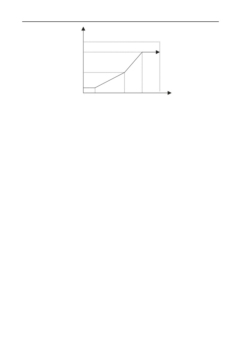
Take 0 ~ 10V AI1 for setting frequency as an example: AI1 selects curve 1, setting
frequency and AI1 relationship as shown in Fig. 7-11.
130
7 Detailed function specification
Freq.
50.00Hz
45.00Hz
30.00Hz
2.50Hz
AI1
2V
5V
7.5V
10V
F06.01=20.0%
F06.02=5.0%
F06.03=50.0%
F06.04=60.0%
F6.05=75.0%
F06.06=90.0%
F06.21=0
Fig. 7-11 AI1 selects curve 1 frequency setting
131
7 Detailed function specification
7.8 Analog quantity, Pulse input function parameter group: F07
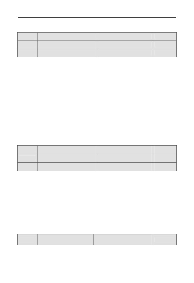
F07.00
AI1 input filter time
Range: 0.000~9.999s
0.050s
F07.01
AI1 setting gain
Range: 0.000~9.999
1.004
F07.02
AI1 setting bias
Range: 0.0~100.0%
0.5%
AI1 input filter time, is used to set AI1 software filter time. When field analog
quantity is easily interrupted, increase filter time to make the analog quantity
check stable, but when filter time is greater, the response time of analog quantity
check is slower. Please set according to the actual situation.
AI1 setting bias is indicated with Max. input (10V or 20mA) percentage, which is
used to set up and down translation quantity of AI1 analog input. Take voltage
input, bias positive as an example, the adjustment relationship of setting bias and
gain adjustment before and after adjustment is as follows:
Analog input AI(after revise)= input gai(F07.01)× Analog input AI(before
revise)+setting bias(F07.02)×10V
Taking current input and bias positive as an example, the adjustment relationship
between gain adjustment and setting bias is as follows:
Analog input AI(after revise)= input gai(F07.01)× Analog input AI(before
revise)+setting bias(F07.02)×20mA
F07.03
AI2 input filter time
Range: 0.000~9.999s
0.050s
F07.04
AI2 setting gain
Range: 0.000~9.999
1.003
F07.05
AI2 setting bias
Range: 0.0~100.0%
0.1%
Parameter F07.03 ~ F7.05 is used to set analog quantity input AI2 filter time ,
gain and setting bias, For detail using method, please refer to analog quantity
input AI1. Take voltage input, bias positive as an example, the adjustment
relationship between gain adjustment and setting bias is as follows:
Analog input AI(after revise)= input gai(F07.04)× Analog input AI(before
revise)+setting bias(F07.05)×10V
Taking current input and bias positive as an example, the adjustment relationship
between gain adjustment and setting bias is as follows:
Analog input AI(after revise)= input gai(F07.04)× Analog input AI(before
revise)+setting bias(F07.05)×20mA
Analog setting bias
Range: units digit: 0,1
F07.06
01
polarity
tens digit: 0,1
Units digit: AI1 setting bias polarity
0: Positive polarity.
1: Negative polarity.
132
7 Detailed function specification
Tens digit: AI2 setting bias polarity
0: Positive polarity.
1: Negative polarity.
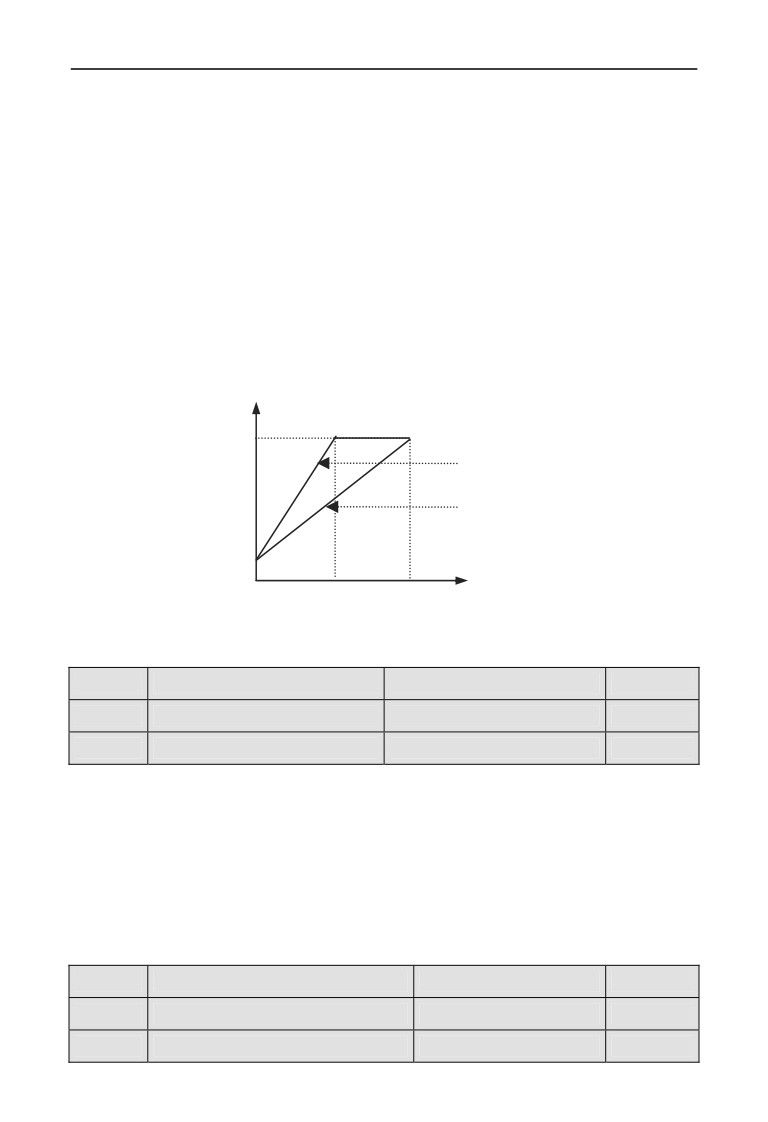
Parameter F07.06 is used to set analog quantity AI1 and when AI2 counts the
polarity of bias. Take voltage input as an example, when F07.06 units are set as 0:
Analog input AI1(after revise) = input gain(F07.01)×Analog input AI1(before
revise)+ Setting bias(F07.02)×10V
When F7.06 units are set as 1:
Analog input AI1(after revise) = input gain(F07.01)×Analog input AI1(before
revise)- Setting bias(F07.02)×10V
Output Volt. after AI1 adjustment
10V
input gain =2
input gain =1
Bias voltage
Set voltage after AI1 filter
0
5V
10V
Fig. 7-12 AI1 adjustment
F07.07
Pulse input filter time
Range: 0.000~9.999s
0.000s
F07.08
Pulse input gain
Range: 0.000~9.999
1.000
F07.09
Pulse input Max. frequency
Range: 0.01~50.00KHz
10.00KHz
F07.07, F07.08 parameter defines filter time and gain when frequency channel
selection terminal pulse is set. When setting filter time, Please be noted that the
longer the filter time is, the slower the change rate of output frequency is. So set
filter time properly according to the actual situation. Pulse width gain is for
impulse quantity of current input impulse terminal.
F7.09 parameter defines frequency input range when frequency setting channel
selection terminal pulse is set. When actual input frequency is greater than the set
Max. frequency, deal with it according to Max. frequency.
F07.10
Pulse width input filter time
Range: 0.000~9.999s
0.000s
F07.11
Pulse width input gain
Range: 0.000~9.999
1.000
F07.12
Pulse width input logic setting
Range: 0,1
0
133
7 Detailed function specification
F07.13
Pulse width Max. input width
Range: 0.1~999.9ms
100.0ms
F07.10, F07.11 parameter defines filter time and gain when frequency channel
selection terminal pulse width is set. When setting filter time, Please be noted that
when the Max. pulse width set in F07.13 is smaller, the filter time is not suggested
to be set too long, otherwise the response time of output frequency will be very
slow. Pulse width gain is for impulse width duty cycle of current impulse width
input terminal
0: Positive logic.
1: Negative logic.
F07.12 defines valid level of digital quantity input X8 channel input pulse when
frequency channel selection terminal pulse width is set. The applications shall go
with double polarity working state of X input terminal.
F07.13 parameter defines the width range of input valid pulse when frequency
setting channel selection terminal pulse width is set.
F07.14
Reserved
F07.15
Reserved
F07.16
Reserved
F07.17
Reserved
134
7 Detailed function specification
7.9 On-off input function parameter group: F08
Input terminal positive and
F08.00
Range: 0000~FFFF
0000
negative logic setting
thousands
hundreds
tens
units
BIT0: X1 positive and negative logic definition
BIT1: X2 positive and negative logic definition
BIT2:X3 positive and negative logic definition
BIT3:X4 positive and negative logic definition
BIT: X5 positive and negative logic definition
BIT1: X6 positive and negative logic definition
BIT2:X7 positive and negative logic definition
BIT3:X8 positive and negative logic definition
BIT0: EX1 positive and negative logic definition
BIT1: EX2 positive and negative logic definition
BIT2: EX3 positive and negative logic definition
BIT3:EX4 positive and negative logic definition
BIT0: EX5 positive and negative logic definition
BIT1:EX6 positive and negative logic definition
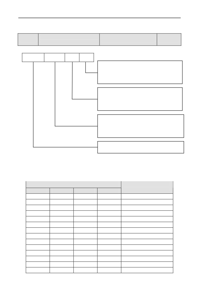
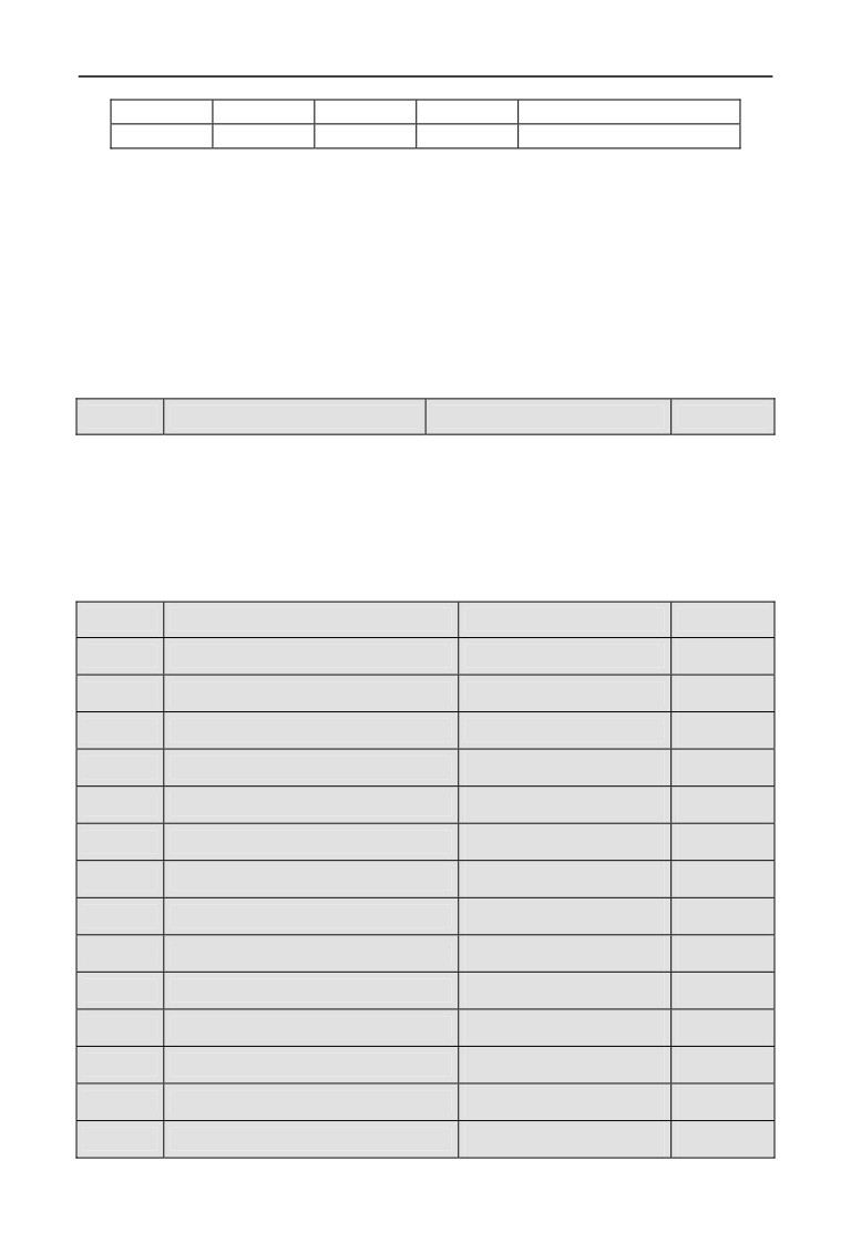
The setting of this parameter is finally converted to binary setting, relationship
between binary setting and hexadecimal is as shown in table 7-2.
Table 7-2 Relationship between binary setting and bit displayed value
Binary setting
Hexadecimal
BI3
BIT2
BIT1
BIT0
(bit displayed value)
0
0
0
0
0
0
0
0
1
1
0
0
1
0
2
0
0
1
1
3
0
1
0
0
4
0
1
0
1
5
0
1
1
0
6
0
1
1
1
7
1
0
0
0
8
1
0
0
1
9
1
0
1
0
A
1
0
1
1
B
1
1
0
0
C
1
1
0
1
D
135
7 Detailed function specification
1
1
1
0
E
1
1
1
1
F
Bit refers to units, tens, hundreds or thousands displayed in operation panel.
F08.00 parameter defines valid logic state of Xi input terminal:
Positive logic: Xi terminal and corresponding common port closed valid, opened
invalid;
Negative logic: Xi terminal and corresponding common port closed invalid,
opened valid;
When BIT selects 0, it indicates positive logic; 1 indicates negative logic. Proper
setting of this parameter can realize correct logic input without changing terminal
wiring.
F08.01
Input terminal filter time
Range: 0.000~1.000s
0.010s
F08.01 parameter sets filter time of input terminal check. When input terminal
state is changed, the terminal state change is valid only when the set filter time is
unchanged. Otherwise, it will remain the last state, thus effectively reduce
malfunction caused by interruption. The group C monitor state is for the state of
the disposed parameter. When demand terminal as the high speed function, low
down the value of this parameter is needed in case losing the signal.
F08.02
X1 Input terminal closed time
Range: 0.00~99.99s
0.00s
F08.03
X1 Input terminal opened time
Range: 0.00~99.99s
0.00s
F08.04
X2 Input terminal closed time
Range: 0.00~99.99s
0.00s
F08.05
X2 Input terminal opened time
Range: 0.00~99.99s
0.00s
F08.06
X3 Input terminal closed time
Range: 0.00~99.99s
0.00s
F08.07
X3 Input terminal opened time
Range: 0.00~99.99s
0.00s
F08.08
X4 Input terminal closed time
Range: 0.00~99.99s
0.00s
F08.09
X4 Input terminal opened time
Range: 0.00~99.99s
0.00s
F08.10
X5 Input terminal closed time
Range: 0.00~99.99s
0.00s
F08.11
X5 Input terminal opened time
Range: 0.00~99.99s
0.00s
F08.12
X6 Input terminal closed time
Range: 0.00~99.99s
0.00s
F08.13
X6 Input terminal opened time
Range: 0.00~99.99s
0.00s
F08.14
X7 Input terminal closed time
Range: 0.00~99.99s
0.00s
F08.15
X7 Input terminal opened time
Range: 0.00~99.99s
0.00s
F08.16
X8 Input terminal closed time
Range: 0.00~99.99s
0.00s
136
7 Detailed function specification
F08.17
X8 Input terminal opened time
Range: 0.00~99.99s
0.00s
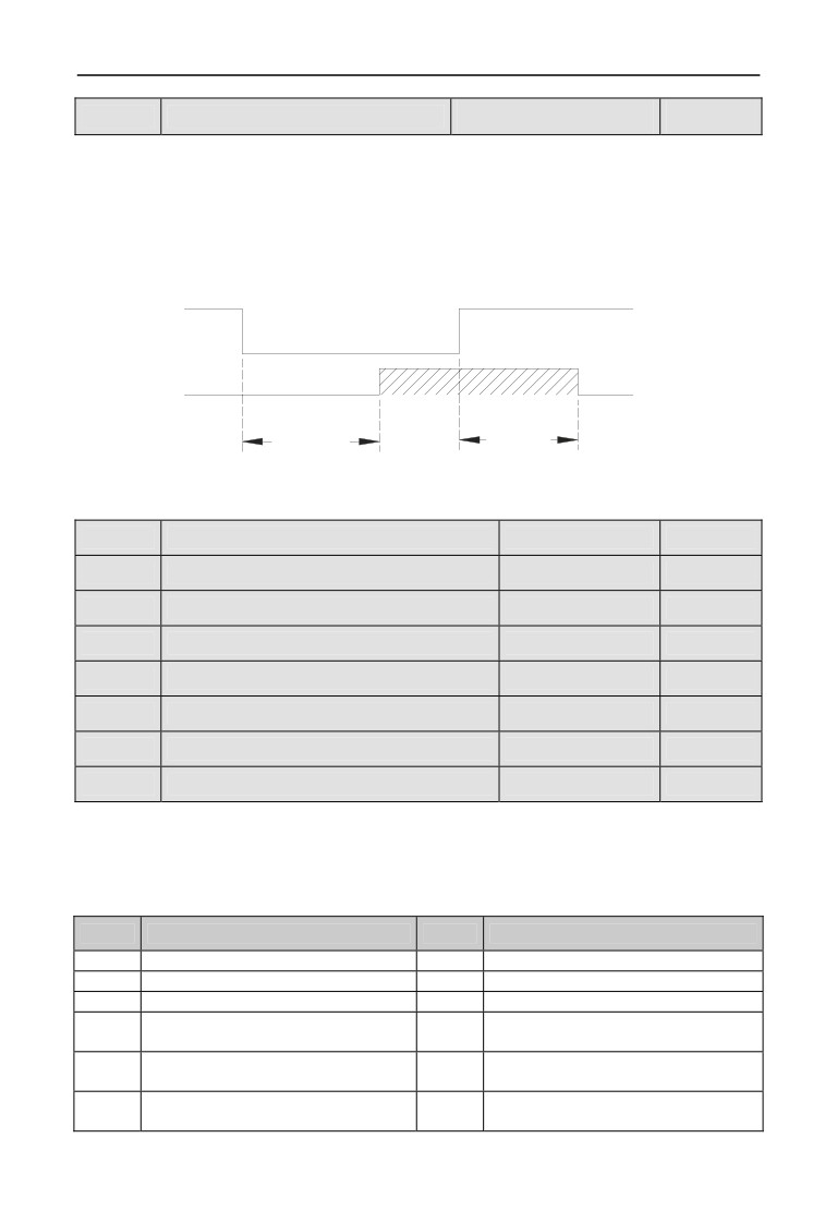
F08.02 ~ F08.17 parameter defines the corresponding delay time of Xi input
terminal from closed to opened or opened to closed so as to meet user’s multiple
requirements. This parameter does not affect the monitor value of input terminal
state. You can revise the parameter to control the filtering when the interruption is
strong.
Xi Level
Invalid
Invalid
Valid
Xi Valid
On-delay
Off-delay
Fig. 7-13 closed and opened delay
F08.18
Input terminal X1 function selection
Range: 0~96
1
F08.19
Input terminal X2 function selection
Range: 0~96
2
F08.20
Input terminal X3 function selection
Range: 0~96
0
F08.21
Input terminal X4 function selection
Range: 0~96
0
F08.22
Input terminal X5 function selection
Range: 0~96
0
F08.23
Input terminal X6 function selection
Range: 0~96
0
F08.24
Input terminal X7 function selection
Range: 0~96
0
F08.25
Input terminal X8 function selection
Range: 0~96
0
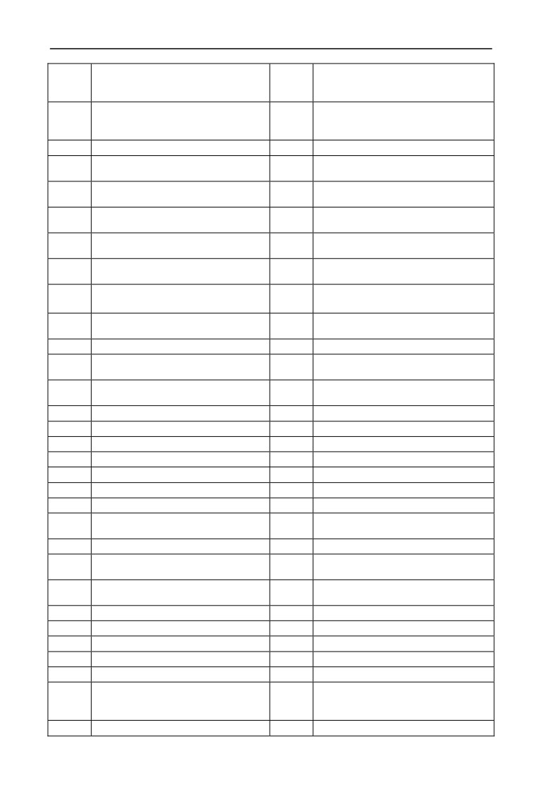
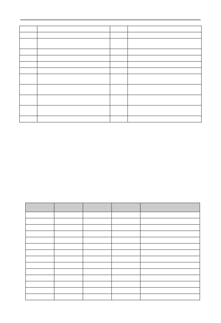
Multi-functional input terminal X1 ~ X8 provides users with up to 95 selections,
which can be selected based on actual applications. For details, please refer to
parameter function Table 7-3.
Table 7-3 Multi-functional input selection function table
Content
Function
Content
Function
0
Leave control terminal unused
49
Auxiliary frequency reset
1
Forward running FWD terminal
50
Command switchover to panel
2
Reverse running REV terminal
51
Command switchover to terminal
Command switchover to
3
External forward jogging control
52
communication
Running command Channel selection
4
External reverse jogging control
53
terminal 1
Running command Channel selection
5
Multi-step speed control terminal 1
54
terminal 2
137
7 Detailed function specification
Forward prohibited command
6
Multi-step speed control terminal 2
55
(Stop according to the stop mode,
invalid for jogging command)
Reverse prohibited command
7
Multi-step speed control terminal 3
56
(Stop according to the stop mode,
invalid for jogging command)
8
Multi-step speed control terminal 4
57
Swinging frequency input
Acceleration/deceleration
time
9
58
Resetting state of swinging frequency
selection terminal 1
Acceleration/deceleration
time
10
59
Interior counter reset end
selection terminal 2
Acceleration/deceleration
time
11
60
Interior counter input end
selection terminal 3
Acceleration/deceleration
time
12
61
Internal timer resetting
selection terminal 4
Main and auxiliary frequency
13
62
Internal timer triggering
operational rule selection terminal 1
Main and auxiliary frequency
14
63
Length count input
operational rule selection terminal 2
Main and auxiliary frequency
15
64
Length reset
operational rule selection terminal 3
16
Frequency ascending command (UP)
65
Reset this operation time
Frequency descending command
17
66
Reserved
(DOWN)
Frequency
ascending/descending
18
67
Reserved
frequency resetting
19
Multi-step closed loop terminal 1
68
Reserved
20
Multi-step closed loop terminal 2
69
Reserved
21
Multi-step closed loop terminal 3
70
Reserved
22
External equipment failure input
71
Reserved
23
External interruption input
72
Reserved
24
External resetting input
73
Reserved
25
Free stop input
74
Reserved
External
stop
instruction—Stop
26
75
Reserved
according to the stop mode
27
stop DC braking input command DB
76
Reserved
inverter running prohibited—Stop
28
77
Reserved
according to the stop mode
Acceleration/deceleration prohibited
29
78
Reserved
command
30
Three-wire running control
79
Reserved
31
Process PID invalid
80
Reserved
32
Process PID stop
81
Reserved
33
Process PID integral holding
82
Reserved
34
Process PID integral resetting
83
Reserved
Process PID function negation
35
(Closed loop adjustment feature
84
Reserved
negation)
36
Simple PLC invalid
85
Reserved
138
7 Detailed function specification
37
Simple PLC halted
86
Reserved
38
Simple PLC stop state resetting
87
Reserved
Main frequency switchover to digit
39
88
Reserved
(keypad)
40
Main frequency switchover to AI1
89
Reserved
41
Main frequency switchover to AI2
90
Reserved
42
Main frequency switchover to EAI1
91
Reserved
43
Main frequency switchover to EAI2
92
Pulse frequency input (X8 VALID)
Main frequency setting channel
Pulse width PWM INPUT
(X8
44
93
selection terminal 1
VALID)
Main frequency setting channel
45
94
Reserved
selection terminal 2
Main frequency setting channel
46
95
Reserved
selection terminal 3
Main frequency setting channel
47
96
Reserved
selection terminal 4
48
Clear auxiliary frequency
-
-
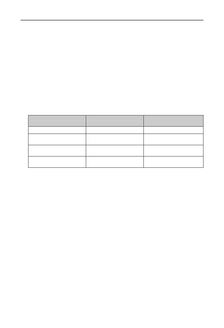
Function introduction in Table 7-3 is as shown below:
1,
2: External command terminal. When running command channel is
terminal running command, control inverter’s forward and reverse by external
terminal.
3, 4: External jogging command terminal. Set as any running command
channel setting running command, control inverter’s jogging forward and jogging
reverse by external terminal.
5 ~ 8: Multi-step running terminal. By setting these functions’ terminal
ON/OFF combination, up to 15 multi-step running frequencies can be set. The
increase and decrease time of each step corresponds to the each step time.
Table 7-4 Multi-step running selection table
K4
K3
K2
K1
Frequency setting
OFF
OFF
OFF
OFF
Other running frequencies
OFF
OFF
OFF
ON
Multi-step frequency 1
OFF
OFF
ON
OFF
Multi-step frequency 2
OFF
OFF
ON
ON
Multi-step frequency 3
OFF
ON
OFF
OFF
Multi-step frequency 4
OFF
ON
OFF
ON
Multi-step frequency 5
OFF
ON
ON
OFF
Multi-step frequency 6
OFF
ON
ON
ON
Multi-step frequency 7
ON
OFF
OFF
OFF
Multi-step frequency 8
ON
OFF
OFF
ON
Multi-step frequency 9
ON
OFF
ON
OFF
Multi-step frequency 10
ON
OFF
ON
ON
Multi-step frequency 11
ON
ON
OFF
OFF
Multi-step frequency 12
ON
ON
OFF
ON
Multi-step frequency 13
139
7 Detailed function specification
ON
ON
ON
OFF
Multi-step frequency 14
ON
ON
ON
ON
Multi-step frequency 15
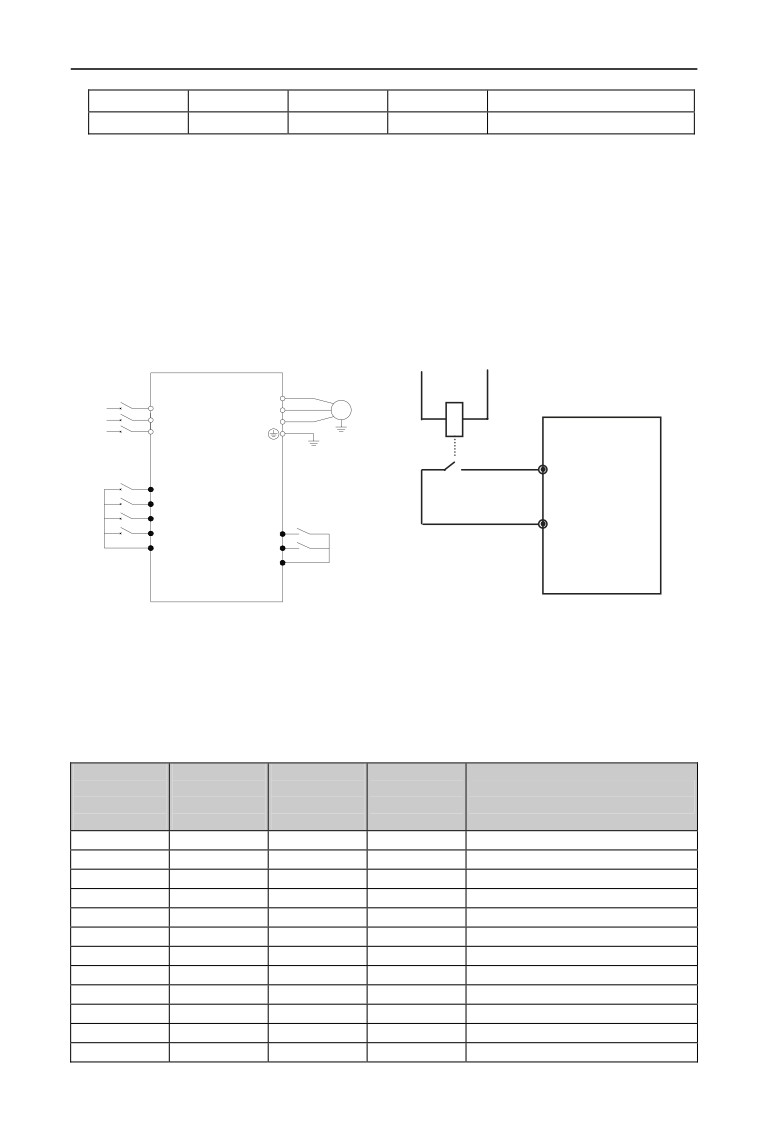
When using multi-step speed to run and simple PLC to run, use multi-step speed
frequency (F10.31 ~ F10.45) above, take multi-step speed running as an example:
Define control terminal X1, X2, X3, X4:
When F08.18=5, F08.19=6, F08.20=7, F08.21= 8, X1, X2, X3, X4 are used to
define multi-step speed running, as shown in Fig. 7-14.
Fig. 7-14 takes terminal running command channel as an example, X5 is set as
forward terminal, X6 is reverse terminal, to control by forward and reverse
running.
3 phase breaker
KM
U
3 phase
R
V
M
AC
S
W
Power
T
EN500/EN600
X5
K1
X1
K2
X2
K3
X3
K4
K5
COM
X4
X5
K6
COM
X6
COM
Fig. 7-14 Multi-step speed running wiring
Fig. 7-15 Peripheral equipment fault Normally Open
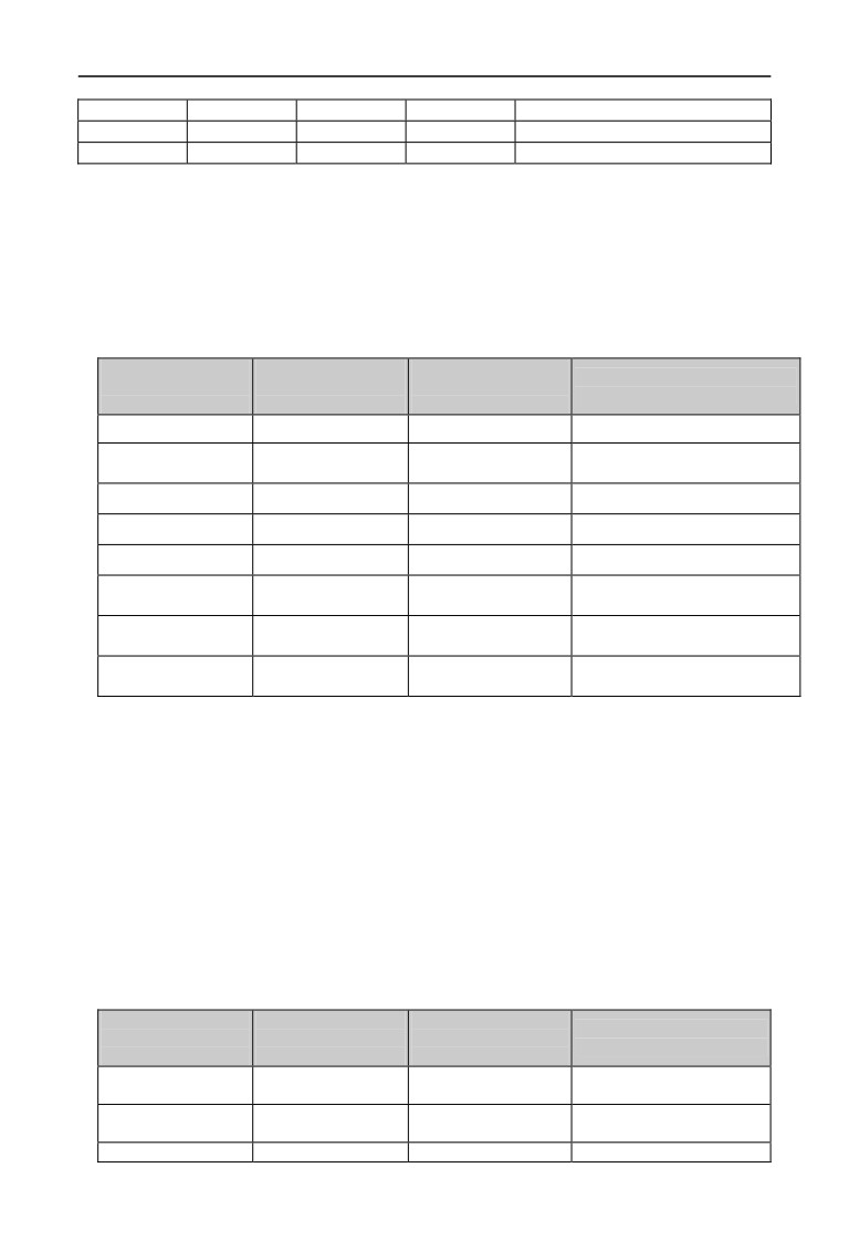
9 ~ 12: Acceleration/deceleration time terminal selection. By ON/OFF of
acceleration/deceleration time terminal, acceleration/deceleration time 1 ~ 15 can be
selected. For details, see Table 7-5:
Table 7-5 Acceleration/deceleration time terminal selection
Acceleration/
Acceleration/
Acceleration/
Acceleration/
deceleration
deceleration
deceleration
deceleration
Acceleration/deceleration time
time selection
time selection
time selection
time selection
selection
terminal 4
terminal 3
terminal 2
terminal 1
OFF
OFF
OFF
ON
Acceleration/deceleration time 1
OFF
OFF
ON
OFF
Acceleration/deceleration time 2
OFF
OFF
ON
ON
Acceleration/deceleration time 3
OFF
ON
OFF
OFF
Acceleration/deceleration time 4
OFF
ON
OFF
ON
Acceleration/deceleration time 5
OFF
ON
ON
OFF
Acceleration/deceleration time 6
OFF
ON
ON
ON
Acceleration/deceleration time 7
ON
OFF
OFF
OFF
Acceleration/deceleration time 8
ON
OFF
OFF
ON
Acceleration/deceleration time 9
ON
OFF
ON
OFF
Acceleration/deceleration time 10
ON
OFF
ON
ON
Acceleration/deceleration time 11
ON
ON
OFF
OFF
Acceleration/deceleration time 12
140
7 Detailed function specification
ON
ON
OFF
ON
Acceleration/deceleration time 13
ON
ON
ON
OFF
Acceleration/deceleration time 14
ON
ON
ON
ON
Acceleration/deceleration time 15
13
~
15: Main and auxiliary frequency operational rule selection
terminal. By ON/OFF of frequency setting channel selection terminal 13, 14, and
15, 7 kinds of main and auxiliary frequency operational rules defined in F01.06
parameter can be realized. Switchover between main and auxiliary operational
rule terminal is prior to function code F01.06 setting. For details, please see table
7-6:
Table 7-6 Selection table of terminal main and auxiliary frequency operational rule
Main and auxiliary
Main and auxiliary
Main and auxiliary
Main and auxiliary operational
operational rule
operational rule
operational rule
rule selection
selection terminal 3
selection terminal 2
selection terminal 1
OFF
OFF
OFF
Decided by F01.06
Synthesized frequency is
OFF
OFF
ON
sub-frequency
OFF
ON
OFF
Operation rule: addition
OFF
ON
ON
Operation rule: subtraction
ON
OFF
OFF
Operation rule: multiplication
Synthesized frequency is Max.
ON
OFF
ON
value
Synthesized frequency is min.
ON
ON
OFF
value
Synthesized frequency is
ON
ON
ON
nonzero value
16, 17: Frequency ascending command UP/descending command DOWN.
Realize frequency ascending or descending by control terminal, substitute
operation keypad for remote control. Normal running F01.00 or F01.03 set as 3 is
valid. Ascending/descending rate is set in F18.06 and F18.07.
18: Frequency ascending/descending frequency resetting.
When frequency setting is set as terminal UP/DOWM, this terminal can
eliminate the set frequency value by terminal UP/DOWN.
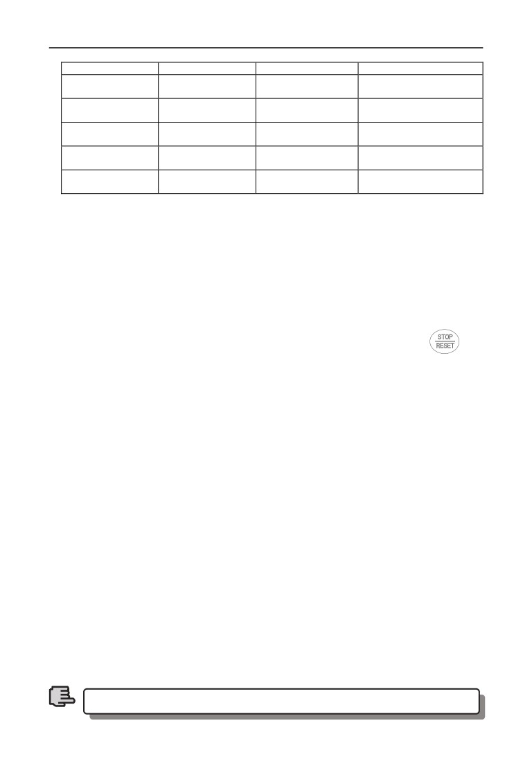
19 ~ 21: Multi-step closed loop setting terminal. By ON/OFF of multi-step
closed loop setting terminal, Table 7-7 Multi-step closed loop setting selection can
be realized.
Table 7-7 Multi-step closed loop setting selection table
Multi-step closed
Multi-step closed
Multi-step closed loop
Multi-step closed loop
loop setting
loop setting
setting
setting selection
selection terminal 3
selection terminal 2
selection terminal 1
Closed loop setting decided
OFF
OFF
OFF
by F11.01
Multi-step closed loop
OFF
OFF
ON
setting 1
OFF
ON
OFF
Multi-step closed loop
141
7 Detailed function specification
setting 2
Multi-step closed loop
OFF
ON
ON
setting 3
Multi-step closed loop
ON
OFF
OFF
setting 4
Multi-step closed loop
ON
OFF
ON
setting 5
Multi-step closed loop
ON
ON
OFF
setting 6
Multi-step closed loop
ON
ON
ON
setting 7
22: External equipment failure jump-in. with this terminal, peripheral
equipment fault signal can be input, which is convenient for inverter to perform
fault monitoring for peripheral equipment, as shown in Fig. 7-15.
23: External interruption input. When the inverter is running, after receiving
external interruption signal, it blocks output, and runs with zero frequency. Once
external interruption signal is released, and inverter running command is still valid,
inverter auto revolving speed tracking starts, the inverter restarts.
24: External resetting input. When fault alarm occurs to the inverter, you
can reset fault by this terminal. Its function and operation keypad
key
function are in accordance.
25: Free stop input. The purpose of this function and free stop set in F02.11
is the same, but here it uses control terminal to realize, which is convenient for
remote control.
26: External stop instruction. This command is effective for all running
command channel, when this function terminal is effective, the inverter stops
running according to mode set by F2.11.
27: Stop DC braking input command DB. Implement DC braking to the
motor during stop by control terminal so as to realize emergency stop and accurate
position of the motor. During deceleration stop, if this function terminal closed,
when frequency is lower than the brake starting frequency F02.14, it will brake
according to brake current defined in F02.16. It will not stop until terminal is
opened.
28: Inverter running prohibited. The running inverter stops freely when
this terminal is effective, and forbidden to start in waiting status. It is mainly
applied to occasion needing safe linkage.
29: Acceleration/deceleration prohibited command. When this function is
valid, keep the motor away from any external signal (except stop command),
maintain current revolving speed running.
This function is invalid in normal deceleration stop process.
Note
142
7 Detailed function specification
30: Three-wire running control. Refer to F08.26 operating mode (Three-wire
operating mode) function introduction.
31: Process PID invalid. Realize flexible switchover in low-level running
mode under closed-loop running status.
1. Switchover between closed-loop and low level running mode can
be available only when the inverter runs in closed-loop mode
(F11.00=1 or F12.00=1).
2.When switching to low-level running mode, start-stop control,
Note
direction and acceleration/deceleration time comply with
relevant setting of running mode.
32: Process PID stop. Invalid when PID stops, when inverter maintains
current output frequency, PID regulation of frequency source is no more
performed.
33: Process PID integral holding. PID integral impact maintains, and will
not regulate according to the output quantity.
34: Process PID integral resetting. When the terminal is valid, PID integral
regulation function halts, but PID proportional control and differential control
function are still valid.
35: Process PID function negation. When the terminal is valid, direction of
PID effect and setting direction of F11.13 is opposite.
36: simple PLC invalid. Realize flexible switchover in low-level running
mode under PLC running status.
1. Switchover between PLC and low level running mode can be
available only when the inverter runs in PLC mode (F10.00 unit’s
digit is not 0).
2. When switching to low-level running mode, start-stop control,
Note
direction and acceleration/deceleration time comply with relevant
setting of running mode.
37: Simple PLC halted. It is to control the stop of running PLC, when the
terminal is valid, the inverter runs at zero frequency, PLC running does not time;
after invalid implementation, auto revolving speed tracking starts and keep on
running PLC.
38: Simple PLC stop state resetting. Under stop status of PLC running
mode, will clear PLC run step, runtime, run frequency etc. recorded when PLC
running stops if this terminal is effective, please see F10 group function
description.
143
7 Detailed function specification
39: Main frequency switchover to digital setting (keypad). The main
frequency provision channel is switched to keypad digital provision when this
terminal is valid (setting frequency by keypad up and down key).
40: Main frequency switchover to AI1. The main frequency provision
channel is switched to analog quantity AI1 provision when this terminal is valid
41: Main frequency switchover to AI2. The main frequency provision
channel is switched to analog quantity AI2 provision when this terminal is valid
42: Main frequency switchover to EAI1. When extended analog quantity is
valid, the main frequency provision channel is switched to extended analog
quantity EAI1 provision when this terminal is valid,
43: Main frequency switchover to EAI2. When extended analog quantity is
valid,
, the main frequency provision channel switchover to extended analog
quantity EAI2 provision when this terminal is valid.
44 ~ 47: Main frequency setting channel selection terminal. By ON/OFF
of selection terminal 1 ~ 4, Free selection of main frequency setting channel can
be realized by terminal. The priority of main frequency setting channel selection
terminal (terminal function 44 ~ 47) is higher than the main frequency switchover
to (terminal function 41, 42, 43). For details, see table 7-8.
Table 7-8 Main frequency setting channel selection terminal
Channel
Channel
Channel
Channel
Main frequency setting channel
selection
selection
selection
selection
selection terminal
terminal 4
terminal 3
terminal 2
terminal 1
Operation keypad digital
OFF
OFF
OFF
ON
setting
OFF
OFF
ON
OFF
AI1 analog setting
OFF
OFF
ON
ON
AI2 analog setting
OFF
ON
OFF
OFF
Terminal UP/DOWN setting
OFF
ON
OFF
ON
Communication setting
OFF
ON
ON
OFF
EAI1 analog setting (extended)
OFF
ON
ON
ON
EAI2 analog setting (extended)
ON
OFF
OFF
OFF
rapid pulse setting (X8)
ON
OFF
OFF
ON
Pulse width setting (X8)
Terminal encoder setting (X1,
ON
OFF
ON
OFF
X2)
Keypad analog potentiometer
ON
OFF
ON
ON
setting (optional)
ON
ON
OFF
OFF
Reserved
ON
ON
OFF
ON
Reserved
ON
ON
ON
OFF
Reserved
48: Auxiliary frequency reset. Only valid for digit auxiliary frequency,
when this function terminal is valid, reset auxiliary frequency setting quantity,
setting frequency is completely decided by main frequency setting channel.
144
7 Detailed function specification
49: Command switchover to panel. When current command source is reset
by terminal or communication, switchover between current command source and
keypad command setting can be realized by this terminal.
50: Command switchover to terminal. When current command source is
reset by keypad or communication, switchover between current command source
and terminal command setting can be realized by this terminal.
51: Command switchover to communication. When current command
source is reset by keypad or terminal, switchover between current command
source and communication command setting can be realized by this terminal.
52, 53: Running command Channel selection terminal. For details, please
refer to Table 7-9.
Table 7-9 Running command channel logic mode
Running command channel
Running command channel
Running command channel
selection terminal 2
selection terminal 1
OFF
OFF
Invalid
Operation keypad running
OFF
ON
command channel
Terminal running command
ON
OFF
channel
Communication running
ON
ON
command channel
54: Forward prohibited command. Enable this terminal during the forward
running process, and the inverter stops according to the stop mode. First enable
this terminal, and then forward running enters zero frequency running status.
Jogging running is not affected by this.
55: Reverse prohibited command. Function and
“Forward prohibited
command” are opposite.
56: Swinging frequency input. When the starting mode of swinging
frequency is manual input, this terminal is valid, and swinging frequency function
is valid. See F13 group function parameter instruction. When swinging frequency
is set as manual input, this terminal is invalid, run with preset frequency of
swinging frequency.
57: Resetting state of swinging frequency. When selecting swinging
frequency function, no matter auto or manual input mode, closing this terminal
will clear state information of swinging frequency memorized in the inverter.
When opening this terminal, swinging frequency restarts. For details, please see
F13 group function.
58: Interior counter reset end. Reset inverter built-in counter, and go with
counter triggering signal input. For details, please see parameter F08.27, F08.28.
59: Interior counter input end. Interior counter’s counting pulse input port,
145
7 Detailed function specification
pulse max. frequency: 50.0KHz.
60: Interior timer reset end. Reset inverter built-in timer, goes with timer
triggering-end signal input.
61: Interior timer triggering end. See parameter F08.29 function.
62: Length count input. Length counting input terminal, see fixed length
function of F13 group parameter.
63: Length reset. When the terminal is valid, reset internal length value, see
F13 fixed length function of parameter group.
64: Reset this operation time. When the terminal is valid, the running
counting time of this inverter is reset, see timing running defined in F18 group.
65 ~ 90: Reserved
91: Pulse frequency input (X8 valid). Only valid for multi-functional input
terminal X8, this function terminal accepts pulse signal as frequency setting,
relationship between the input signal pulse frequency and setting frequency is as
shown in F06 and F07 group parameter.
92: Pulse width PWM input (X8 valid). Only valid for multi-functional
input terminal X8, this function terminal accepts PWM signal, check pulse width
as frequency setting, relationship between input PWM Pulse width and setting
frequency is as shown in F06 and F07 group parameter.
93~96:Reserved
F08.26
FWD/REV operating mode selection
Range: 0~4
0
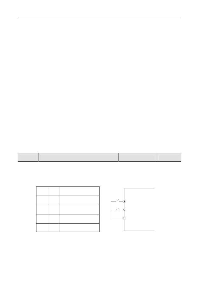
This parameter defines five different modes by controlling external terminal
inverter running.
0: Two-wire control mode 1
K2
K1
Operating command
EN500/EN600
K1
0
0
Stop
FWD
K2
1
0
REV
REV
0
1
FWD
COM
1
1
Stop
Fig. 7-16 Two-wire operating mode 1
146
7 Detailed function specification
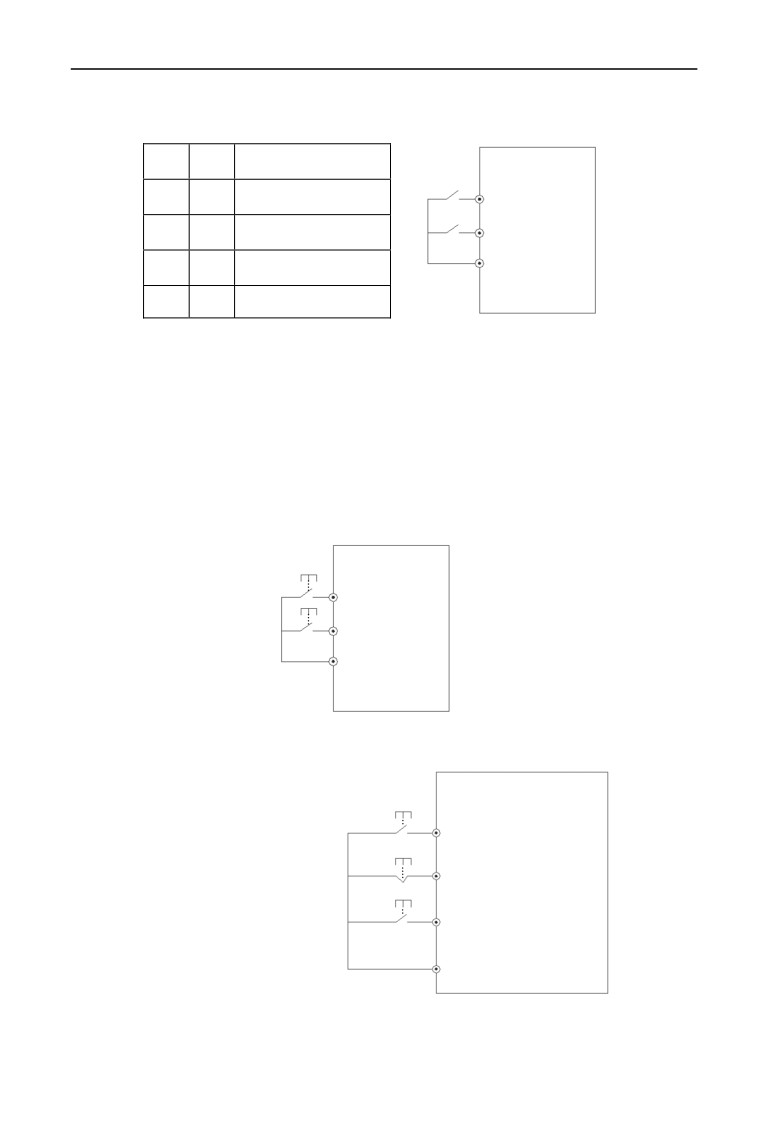
1: Two-wire control mode 2
K2
K1
Operating command
EN500/EN600
K1
0
0
Stop
FWD
K2
1
0
Stop
REV
COM
0
1
FWD
1
1
REV
Fig. 7-17 Two-wire operating mode 2
2: Two-wire control mode 3 (monopulse control mode)
Monopulse control is triggered-type control. After triggering SB1 once, it
forwards runs. Retriggering SB1 once, it stops. Triggering SB1 once, it reversely
runs. Retriggering SB2 once, it stops. If it is forward running, the inverter stops
when triggering SB2 once. Retriggering SB1 once, it stops. If it is reverse running,
the inverter stops when triggering SB1 once.
EN500/EN600
SB1
FWD
SB2
REV
COM
Fig. 7-18 Two-wire control mode 3
3: Three-wire control mode 1
EN500/EN600
Defines are as follows:
SB2
FWD
SB1: stop button
SB1
Xi
SB2: forward button
SB3
SB3: reverse button
REV
COM
Fig. 7-19 Three-wire operating mode 1
Xi is X1 ~ X8’s Multi-functional Input terminal, at this moment, define its
147
7 Detailed function specification
corresponding terminal function as
“Three-wire running control” function of
No.30.
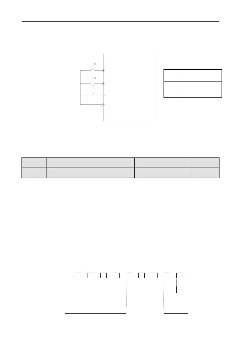
4: Three-wire control mode 2
SB1: stop button
EN500/EN600
SB2: run button
SB2
FWD
Running direction
K2
selection
SB1
Xi
0
Forward
K2
REV
1
Reverse
COM
Fig. 7-20 Three-wire operating mode 2
Xi is X1 ~ X8’s Multi-functional input terminal, At this moment, define its
corresponding terminal function as “Three-wire running control” function of No.
30.
F08.27
Set internal count value to setting
Range: 0~65535
0
F08.28
Specify internal count to setting
Range: 0~65535
0
F08.27 and F08.28 are to additionally define functions of 30 and 31 in 7-10.
When Xi (Counting trigger signal input function terminal) output pulse reaches
F08.27 defined value, Y1 (Y1 is set as internal count value final value to) outputs
one indicating signal, as shown in Fig. 7-21, When Xi inputs the eighth pulse,
Y1outputs one indicating signal. At this moment, F8.27=8.
When Xi (Counting trigger signal input function terminal) output pulse reaches
F08.28 defined value, Y2 (Y2 is set as internal counter specified value to) outputs
one indicating signal, until set count value arrives.
As shown in Fig. 7-21, when Xi inputs the fifth pulse, Y2 starts outputting one
indicating signal. Until set count value 8 arrives, F08.28=5. When specified count
value is greater than set count value, specified count value Invalid.
1
2
3
4
5
6
7
8
9
Xi input
Y1
Y2
Fig. 7-21 set count value setting and specified count value setting
148
7 Detailed function specification
F08.29
Internal timer timing setting
Range: 0.1~6000.0s
60.0s
This parameter sets timing time of inverter internal timer, timer is triggered by
external triggering terminal (Xi terminal function no. is 61), the timer starts timing
upon receiving external triggering signal. After reaching timing time, Yi terminal
outputs a breadth of 0.5s valid pulse signal. When internal timer clearing terminal
is valid (Xi terminal function is set as 60), internal timer is reset.
Terminal pulse encoder
F08.30
Range: 0.01~10.00Hz
1.00Hz
frequency rate
This parameter defines main frequency regulation speed during terminal pulse
encoder setting frequency (F01.00=9). Main frequency terminal encoder pulse
input can only choose channel X1 and X2 combination; auxiliary frequency
terminal encoder pulse input can only choose channel X3 and X4 combination,
and the rate of the auxiliary frequency encoder frequency is the fixed rate.
When 9 is selected in F01.00 and F01.03, X1~X4 can only be used
as encoder frequency setting. Other terminal functions defined by
Note
F08.18~F08.21 are invalid.
F08.31
Reserved
149
7 Detailed function specification
7.10 Switch output function parameter group: F09
Open-collector output terminal Y1
F09.00
Range: 0~60
0
output setting
Open-collector output terminal Y2
F09.01
Range: 0~60
0
output setting
Open-collector output terminal Y3
F09.02
Range: 0~60
0
output setting
Open-collector output terminal Y4
F09.03
Range: 0~60
0
output setting
F09.04
Programmable relay output setting
Range: 0~60
22
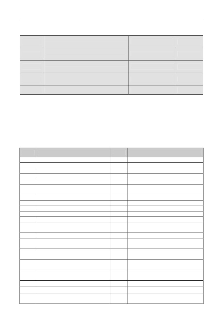
Functions of the above parameters are used to select Y1 ~ Y4 and relay output
terminals. Table 7-10 shows the functions of the above 4 terminals. One function
can be selected repeatedly.
Open-collector (Yi) and high-speed pulse (DO) output share terminal Y4. Y4
terminal as the high-speed pulse function to be modified F00.22 thousands place
to 1.
Table7-10 Output terminals function selection diagram
Setting
Function
Setting
Function
0
No output
31
Set count value reached
1
Frequency inverter running(RUN)
32
Designated count value reached
2
Frequency inverter Forward running
33
Shutdown time arrival of the running
3
Frequency inverter Reverse running
34
Time arrival of the running
4
Frequency inverter DC brake
35
Setup running time arrived
Frequency inverter Ready for
5
36
Setup power-on time arrived
operation(RDY)
6
Shutdown command indicator
37
1st pump variable frequency
7
Zero current state
38
1st pump frequency
8
Over current state
39
2nd pump variable frequency
9
Current 1 arrived
40
2nd pump frequency
10
Current 2 arrived
41
Communication given
Frequency inverter Zero-frequency
11
42
Reserved
output
12
Frequency arriving signal (FAR)
43
Reserved
Frequency level detection signal 1
13
44
Reserved
FDT1
Frequency level detection signal
14
45
Reserved
2(FDT2)
Output frequency arriving upper
15
46
Reserved
limit(FHL)
Output frequency arriving lower
16
47
Reserved
limit(FLL)
17
Frequency 1 arrived
48
Reserved
18
Frequency 2 arrived
49
Reserved
Frequency inverter overload pre- alarm
19
50
Reserved
signal(OL)
150

7 Detailed function specification
Frequency inverter Low voltage
20
51
Reserved
lock-up signal(LU)
21
External stopping command(EXT)
52
Reserved
22
Frequency inverter fault
53
Reserved
23
Frequency inverter warning
54
Reserved
24
Simple PLC operation running
55
Reserved
25
Completion of simple PLC operation
56
Reserved
26
Simple PLC cycle-running completed
57
Reserved
27
Simple PLC suspended
58
Reserved
28
Upper and lower limit of Wobble
59
Reserved
29
Setup length arrived
60
Reserved
30
Internal counter final value arrived
-
-
The instructions of the function output terminals listed in table 7-10 are as below:
0: The terminal function is idle.
1:Frequency inverter is running(RUN).The Drive is in the running state,
output the indicator signal.
2. Frequency inverter is forward running. The Drive is in the forward
running state, output the indicator signal.
3. Frequency inverter is reversed running. The Drive is in reversed
running state, output the indicator signal.
4.Frequency inverter is DC braking. The Drive is in DC braking state,
output the indicator signal.
5. Frequency inverter is ready to run. This signal being valid means that
the Drive bus voltage is normal, the Drive is running and forbidding the terminal
is invalid, it can accept a start command.
6. Shutdown command indicator. When the shutdown command is valid,
output the indictor signal.
7. Zero current is detected. When detected the output meet the zero current
state, output the indicator signal. Please refer to the instruction of F09.12and
F09.13parameters for details.
8. Over current is detected. When the output current meet the over current
detection conditions, output the indicator signal. Please refer to the instruction of
F09.14and F09.15 parameters for details.
9. Current
1 arrived. When the output current reaches the detection
conditions to meet the current 1, output the indicator signal. Please refer to the
instruction of F09.16and F09.17 parameters for details.
10. Current 2 arrived. When the output current reaches the detection
conditions to meet the current 2, output the indicator signal. Please refer to the
instruction of F09.18and F09.19 parameters for details.
11. Frequency inverter Zero frequency output. Please refer to the function
151
7 Detailed function specification
instruction of F09.10and F09.11.
12. Frequency arriving signal(FAR). Please refer to the function instruction
of F09.05.
13. Frequency level detection signal 1(FTD1). Please refer to the function
instruction of F09.06, F09.07.
14. Frequency level detection signal 2(FTD2). Please refer to the function
instruction of F09.08, F09.09.
15. Output frequency reaches upper limit (FHL). When the running
frequency reaches upper limit, the output is indicator signal.
16. Output frequency reaches lower limit (FHL). When the running
frequency reaches lower limit, the output is indicator signal.
17. Frequency 1 arriving output. Please refer to the function instruction of
F09.20, F09.21.
18. Frequency 2 arriving output. Please refer to the function instruction of
F09.22, F09.23.
19. Frequency inverter overload pre-alarm signal. Frequency inverter
output current exceeds F19.06 overload pre-alarm detection levels, and time is
greater than F19.07 overload pre-alarm delay time, output the indicator signal.
20. Frequency inverter Low voltage lock-up signal
(LU).When the
frequency inverter is running, the DC bus voltage below the limit level, output
indication signal.
21. External fault shutdown (EXT).When the frequency inverter appears
external fault trip alarm (E-18), output indication signal.
22. Frequency inverter fault. When the frequency inverter detects fault, the
output is indication signal.
23. Frequency inverter warning. When the frequency inverter detects alarm,
the output is indication signal.
24. Simple PLC during operating. The simple PLC is enabled, and enter
into operation state, output indication signal
25. Simple PLC stage operation completed. When the simple PLC stage
operation is completed, output indication signal (single pulse signal, the width is
500ms).
26. Simple PLC ends after running a cycle. After the completion of a cycle
of simple PLC, output indication signal (single pulse signal, the width is 500ms)
27. Simple PLC pause. When the simple PLC is running into the pause state,
output is indication signal.
28. Wobble upper and lower limit. If the frequency fluctuation range
calculated by center frequency exceeds the upper limit F01.11 or belows lower
152
7 Detailed function specification
limit F01.12 after selecting the wobble function, it will output indication signal, as
shown in Figure 7-22.
Output
Setting
Upper limit
Detection range
freq.
Time
Lower limit
Y
Time
Y1:Wobble upper and lower
Fig.7-22 Wobble amplitude limit
Fig.7-23 Freq. arrival signal output diagram
29. Setup length arrived. When detected the actual length exceeds a set
value F13.08, output indication signal.
30. Internal counter final value arrived. Please refer to the function
instruction of F08.27.
31. Internal counter specified value arrived. Please refer to the function
instruction of F08.28.
32. Internal counter timing meter arrival. Please refer to the function
instruction of F08.29.
33. Shutdown time arrival of the running. Frequency inverter runs longer
than the setting time of F18.12, output indication signal.
34. Time arrival of the running. Frequency inverter runs longer than the
setting time of F18.13, output indication signal.
35. Setup time arrived. Accumulated running time of the frequency inverter
reaches the set accumulated running time (F18.10), output indication signal.
36. Setup power-on time arrived. Accumulated power on time of the
frequency inverter reaches the set accumulated running time (F18.09), the output
indication signal.
37: 1st pump variable frequency.
38: 1st pump frequency.
39: 2nd pump variable frequency.
40: 2nd pump frequency
When using Y1 ~ Y4 achieve two pumps constant pressure water supply, Y1 ~ Y4
functions are arranged in order of 37 to 40. Under constant pressure water supply
mode, the four parameters must all set to this value, the terminal functions can be
achieved
41: Communication given. In this moment the output of Yi is controlled by
communication, Please refer to the related communication protocol for details.
153
7 Detailed function specification
42~60:Reserved
Detection amplitude of
F09.05
Range: 0.00~50.00Hz
5.00Hz
frequency arrival(FAR)
This parameter is added in the definition of Table 7-10 on the 12th functions. As
shown in Figure 7-23, when the inverter output frequency in the setting frequency
of positive and negative detection width, output indication signal.
Range: 0.00Hz~upper
F09.06
FDT1(frequency level)level
10.00Hz
limit frequency
F09.07
FDT1 lag
Range: 0.00~50.00Hz
1.00Hz
Range: 0.00Hz~upper
F09.08
FDT2(frequency level)level
10.00Hz
limit frequency
F09.09
FDT2 lag
Range: 0.00~50.00Hz
1.00Hz
F09.06, F09.07 is in the
definition of Table 7-10 on the 13th
Output freq.
Functions, F09.08, F09.08 is in the
FDT1 level
FDT1 lag
definition of Table 7-10 on the 14th
functions, take an example of 13th
Time
functions: When the output frequency
exceeds a certain setting frequency
Y
(FDT1 level), output indicator
Signal, until the output frequency drops
Time
below the certain frequency FDT1 frequency
level (FDT1 level -FDT1 lag). As shown in
Fig.7-24 Freq. level detection diagram
Figure 7-24.
Zero-frequency signal
Range: 0.00Hz~upper limit
F09.10
0.00Hz
detection value
frequency
Range: 0.00Hz~upper limit
F09.11
Zero-frequency backlash
0.00Hz
frequency
Operating freq.
F09.11
F09.10
Time
Zero freq.
operating
output
Time
Fig.7-25 Zero-frequency signal detection
154