ZETADYN 3BF. Operating instruction (Part.-No. 00163264-GB 2/200) - page 4
Emergency evacuation
12
Emergency evacuation
12.1
Evacuation with 1-phase mains supply 230V AC
Information
The methods of Emergency Evacuation, described in this chapter, are only possible with the types
ZETADYN 3BF011 - ZETADYN 3BF074.
Due to the low power requirements of a synchronous drive, it is possible to carry out an evacuation trip
in the motoric and generatoric direction.
Due to the high level of magnetization current, emergency evacuation with a single-phase mains
supply with asynchronous motors does not make sense.
Characteristics of evacuation with single-phase mains supply:
• Evacuation in motoric and generatoric direction
• Load-independent starts
• Load-independent stopping
• Flush stopping
If there is a mains failure, the mains supply must provide the following voltage to the inverter:
•
230 VAC to feed L1 and L2
The frequency inverter analyses the load ratio between the car and the counterweight during every
start.
The control system starts the evacuation trip by activating:
• Controller enable
• Direction default
• Speed default
Size of the voltage supply
The required performance consists of the following:
Electronic frequency inverter power consumption
+ Control systempower consumption
+ Electromechanical brakes power consumption
+ Other consumers (car light, …) power consumption
+
Motor power consumption during motoric operation with sufficient power
(ask motor manufacturer)
= Real power [W]
Information
The shaft efficiency has a decisive influence on the required power of the single-phase mains supply.
120/200
Emergency evacuation
12.1.1
Parameterisation
(1) The following prerequisites must be present:
The direction of travel of the car is downwards with
Standard
DCP
24V signal on input configured to
Command byte 1, Bit 4 has 1-sig-
"RV2"
nal
Detection of voltage drop
Configure digital input in the Control system menu to PARA2.
Control
|-" f_I08
PARA2
|-"
PARA2
Function I_08
In case of a voltage drop (power failure) the inverter is informed by activating the congured input with
24VDC that a switchover must be made to parameterset 2.
(3) Inform the open loop control about the permissible direction of travel (optional):
Standard
DCP
Configure digital output in the Control system
Status byte 2, Bit 2 = 0 R Car is lighter than coun-
menu to Evac. Dir.
terweight
Evacuation trip will be carried out upwards!
Control
|-" f_O4
Evac.Dir
|-"
Evac.Dir
Status byte 2, Bit 2 = 1 R Car is heavier than
Function O4
counterweight
Evacuation trip will be carried out downwards!
Contact open R Car is lighter than counterweight
Evacuation trip will be carried out upwards!
Output closed R Car is heavier than counter-
weight
Evacuation trip will be carried out downwards!
(4) Evacuation type default
Configure the parameter F_PARA2 = EVA. 1*AC in the Parameter set 2 menu.
Parameter set 2
|-" F_PARA2 EVAC1*AC
|-"
EVAC1*AC
Function parameter set 2
(5) Copying the parameters:
In the menu Parameter set 2 / COPY, select the function PARA->2. After copying, the parameter is
once again OFF.
Parameter set 2
|-" COPY
Off
|-"
Para1R2
Copy parameter
Information
The power failure detection and type of evacuation must be parameterised before copying the
parameters. Only a lower speed of the motor is possible because of the lower mains supply. The
maximum possible speeds for V_2 and V_3 are calculated during the copying process.
121/200
Emergency evacuation
12.2
Evacuation with UPS
Information
The methods of Emergency Evacuation, described in this chapter, are only possible with the types
ZETADYN 3BF011 - ZETADYN 3BF074.
Due to the low power requirements of a synchronous drive, it is possible to carry out an evacuation trip
at half-load or in the direction of the pulling load using a commercially available UPS. An evacuation
trip against the load direction is not possible!
Due to the high level of magnetization current, emergency evacuation with a single-phase mains
supply with asynchronous motors does not make sense.
In case of a mains failure, the UPS supplies the following voltage:
•
230 VAC to feed L1 and L2
During each trip, the frequency inverter analyses the load ratio between the car and the counter-
weight. In case of a voltage drop (mains failure), the frequency inverter informs the control system
which direction is possible for an evacuation trip. The open loop control carries out the evacuation trip
in the corresponding direction.
The control system starts the evacuation trip by activating:
• Controller enable
• Direction preset (in the direction of the pulling load)
• Speed default
12.2.1
Evacuation through UPS with optimum power
Characteristics of evacuation with optimum UPS power:
• Load-independent starts
• Load-independent stopping
• Flush stopping
• With corresponding sizing of the UPS, a trip in the motoric direction is also feasible.
Calculation of the UPS
The required UPS performance consists of the following:
Electronic frequency inverter power consumption
+ Control systempower consumption
+ Electromechanical brakes power consumption
+ Other consumers (car light, …) power consumption
+
Motor power consumption for UPS operation with sufficient power (ask
motor manufacturer)
= Real power UPS [W]
Information
The shaft efficiency has a decisive influence on the required power of the UPS performance.
122/200
Emergency evacuation
12.2.2
Evacuation through UPS with minimum power
Evacuation through UPS with minimum power
• Load-dependent starting, cannot be optimized
• Evacuation only possible in the direction of the pulling load
• Positioning is carried out load dependent; that means step formation could occur.
Calculation of the UPS
The required UPS performance consists of the following:
Electronic frequency inverter power consumption
+ Control systempower consumption
+ Electromechanical brakes power consumption
+ Other consumers (car light, …) power consumption
+
Motor power consumption for UPS operation with reduced power (ask
motor manufacturer)
= Real power UPS [W]
Information
The shaft efficiency has a decisive influence on the required power of the UPS performance.
12.2.3
Parameterisation
(1) The following prerequisites must be present:
The direction of travel of the car is downwards with
Standard
DCP
24V signal on input configured to
Command byte 1, Bit 4 has 1-sig-
"RV2"
nal
Detection of voltage drop
Configure digital input in the Control system menu to PARA2.
Control
|-" f_I08
PARA2
|-"
PARA2
Function I_08
In case of a voltage drop (power failure) the inverter is informed by activating the congured input with
24VDC that a switchover must be made to parameterset 2.
(3) Inform the open loop control about the permissible direction of travel (optional):
Standard
DCP
Configure digital output in the Control system
Status byte 2, Bit 2 = 0 R Car is lighter than coun-
menu to Evac. Dir.
terweight
Evacuation trip will be carried out upwards!
Control
|-" f_O4
Evac.Dir
|-"
Evac.Dir
Status byte 2, Bit 2 = 1 R Car is heavier than
Function O4
counterweight
Evacuation trip will be carried out downwards!
Contact open R Car is lighter than counterweight
Evacuation trip will be carried out upwards!
Output closed R Car is heavier than counter-
weight
Evacuation trip will be carried out downwards!
123/200
Emergency evacuation
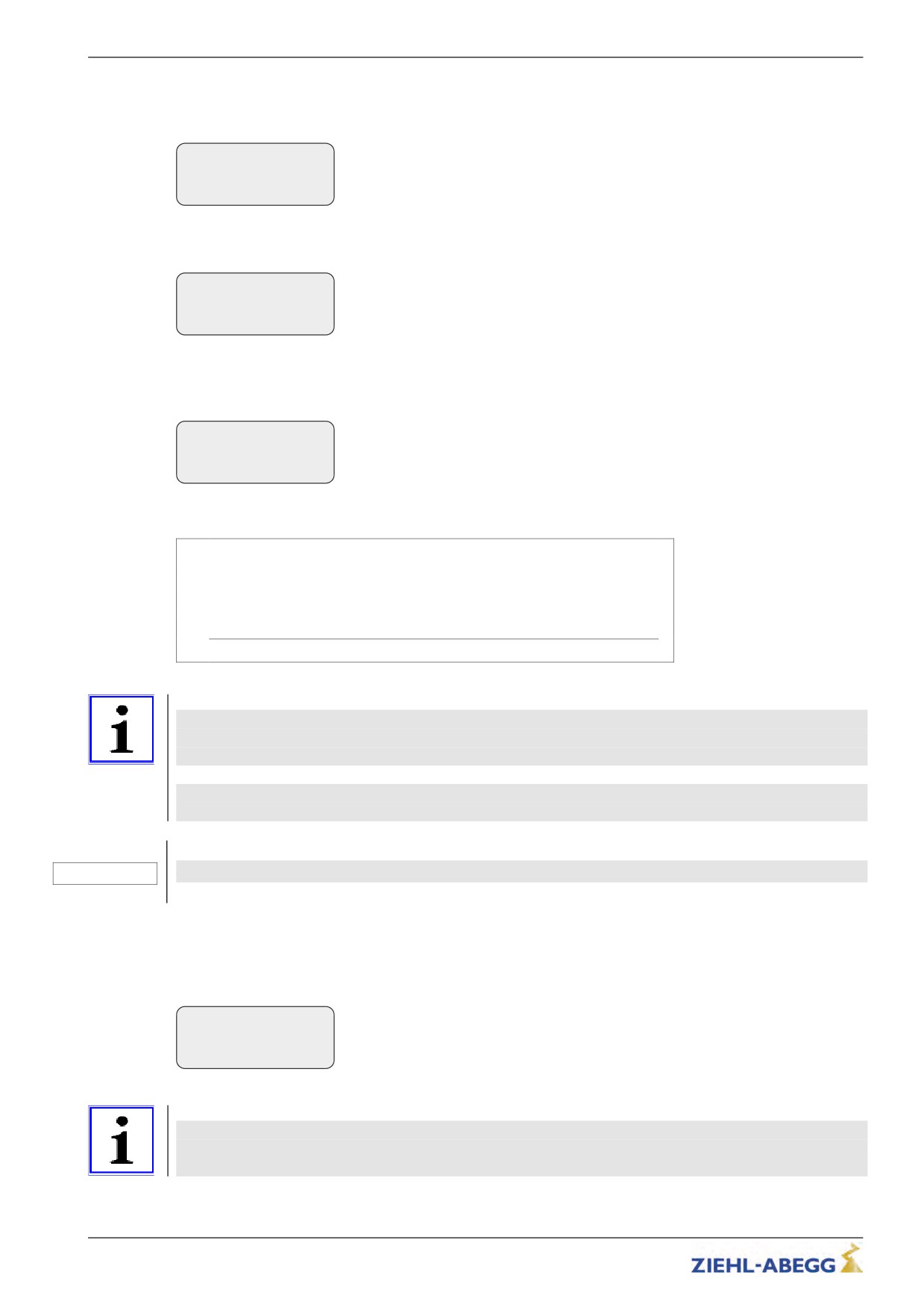
(4) Evacuation type default
Configure the parameter F_PARA2 = UPS in the Parameter set 2 menu.
Parameter set 2
|-" F_PARA2 UPS
|-"
UPS
Function parameter set 2
(5) Presetting the stator resistor in synchronous motors
Configure the synchronous motor's stator resistor in the Parameter set 2/RS_UPS menu
Parameter set 2
|-" RS_UPS
1.00
Ohm
|-"
1.00
Stator resistance (UPS
(6) Limit motor current
Limit the motor current by entering the available UPS power in the "Parameter set 2 / P_UPS"
menu.
Parameter set 2
|-" P_UPS
1.0
kW
|-"
1.0
Max. load of the UPS
Calculating the available UPS power:
UPS power name plate
- Control systempower consumption
- Electromechanical brakes power consumption
- Other consumers (car light, …) power consumption
= Available UPS_power [W]
Information
Entering the UPS power determines the type of UPS evacuation.
Sufficient power: An evacuation trip with the characteristics of an evacuation with optimum UPS
power is implemented.
Not enough power: An evacuation trip with the characteristics of an evacuation with minimal UPS
power is implemented.
Caution!
Setting the value for P_UPS too high can lead to an overloading or destruction of the UPS.
CAUTION!
(7) Copying the parameters
In the menu Parameter set 2 / COPY, select the function PARA->2. After copying, the parameter is
once again OFF.
Parameter set 2
|-" COPY
Off
|-"
PARA1R2
Copy parameter
Information
The power failure detection and type of evacuation must be parameterised before copying the
parameters. Only a lower speed of the motor is possible because of the lower mains supply. The
maximum possible speeds for V_2 and V_3 are calculated during the copying process.
124/200
Emergency evacuation
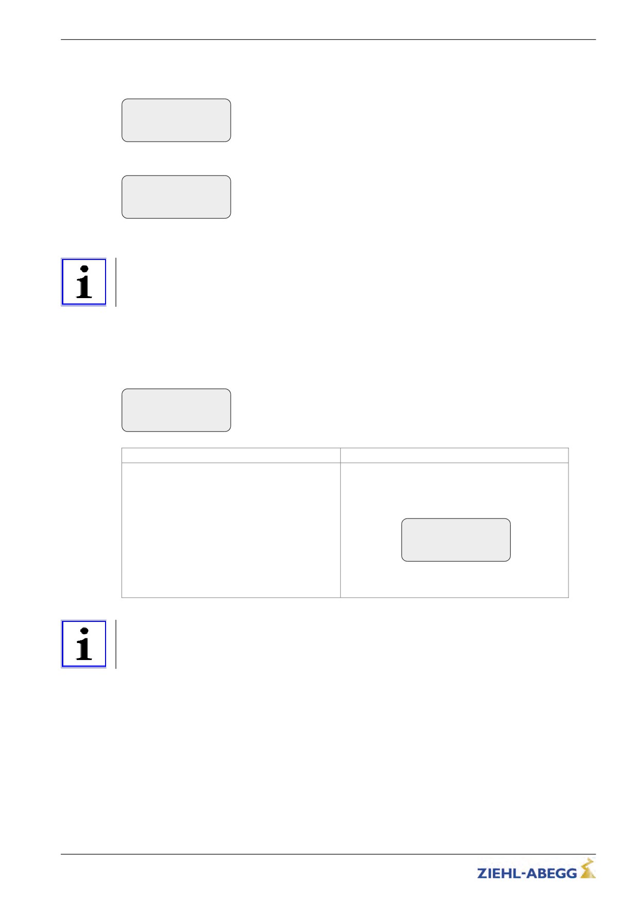
(8) Switch off times in which the motor is kept at speed 0:
Configure in the Start / T_3 = 0 menu
Start-up
|-" T_3
0.0
s
|-"
0.0
Maintain speed=0
Configure in the Stop / T_4 = 0 menu
Start-up
|-" T_4
0.0
s
|-"
0.0
Maintain speed 0
12.3
Improving the positioning
Information
The methods of Emergency Evacuation, described in this chapter, are only possible with the types
ZETADYN 3BF011 - ZETADYN 3BF074.
Due to the reduced UPS power, it is not possible to decelerate the motor until standstill. That means,
at the time when the floor is reached and the brakes are closed, the motor is still moving. The time
delay until the brakes are closed can lead to overshooting the door zone area and thus step formation.
12.3.1
Parameterisation
Configure in the Parameter set 2 / STOP = ON menu
Parameter set 2
|-" STOP
ON
|-"
ON
Stop function
Standard
DCP2 / DCP4
Configure in the "Parameter set 2 / STOP = ON"
Determine overshoot path at the flush position under
menu
full load
Brake is already closed when the switch off for the
Set parameters in the Control/DCP_STP = ... mm
speed V_1is reached.
menu
Control system
|-" DCP_STP 35
mm
|-"
35
Stop before floor level
The brakes are already closed when the distance to
the flush position preset by S_Stop is reached.
Information
The positioning is still load-dependent despite this measure. When travelling at half load, the elevator
can stop too early outside the door zone range with parameter set 2/STOP = ON.
125/200
Emergency evacuation
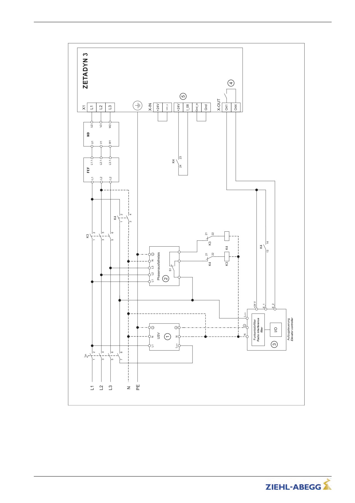
12.4
Connection diagram for UPS to ZETADYN 3
1
Uninterruptible power supply
2
Phase failure relay
3
elevator control system
4
Output paramterised to "Evac.Dir" function (information direction of generator)
5
Input parameterised for "PARA2" function
S1
Relay is active when all 3 phases of the power supply are connected.
E_1
Information voltage failure
E_2
Information direction of generator (can be omitted when extended status bytes evaluated at DCP3 and DCP4)
K3
Normal operation
K4
Operation with uninterruptible power supply
126/200
Emergency evacuation
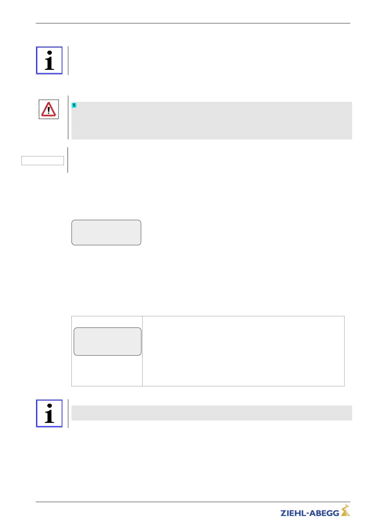
12.5
Emergency evacuation by opening the brakes
Information
The methods of Emergency Evacuation, described in this chapter, are only possible with the types
ZETADYN 3BF011 - ZETADYN 3BF074.
Emergency evacuation through manually or electrically opening the motor brakes until the cabin has
reached the next floor in the direction of the pulling load.
Warning
If an emergency evacuation is carried out by opening the brakes, the motor windings must be
short-circuited for the evacuation to prevent an uncontrolled acceleration of the elevator. The
short-circuit generates a speed-dependent braking torque, sufficient in most cases to limit the
elevator speed to a safe level.
Caution!
Short-circuiting of the motor windings must be permitted by the motor manufacturer. This is tested and
CAUTION!
guaranteed for ZIEHL-ABEGG motors.
12.5.1
Monitor function
Monitoring of evacuation direction and evacuation speed during the evacuation process.
The monitoring function will be activated by a digital input.
Control system
|-" f_I08
41:Monitor
Configure the digital input in the Control system menu to the function 41:Mon-
|-"
41:Monitor
itor.
Function of I08
Activating of the monitoring function
• Switch off the frequency inverter
• activate the digital input with the "Monitoring" function
• Switch on the frequency inverter
• Monitoring function is active
Elevator-Monitor
Speed:
Elevator-Monitor
Speed: 0.2m/s
Display of the actual evacuation speed
Direction: up ▲
Direction:
Distance: +1.24m
Display of the actual evacuation direction
▲ Evacuation speed < Limit V_G1
▲▲ Evacuation speed > Limit V_G1
Distance:
Display of the evacuation distance past
Information
During activated Monitoring-Function, all further functions of the frequency inverter are
locked!
127/200
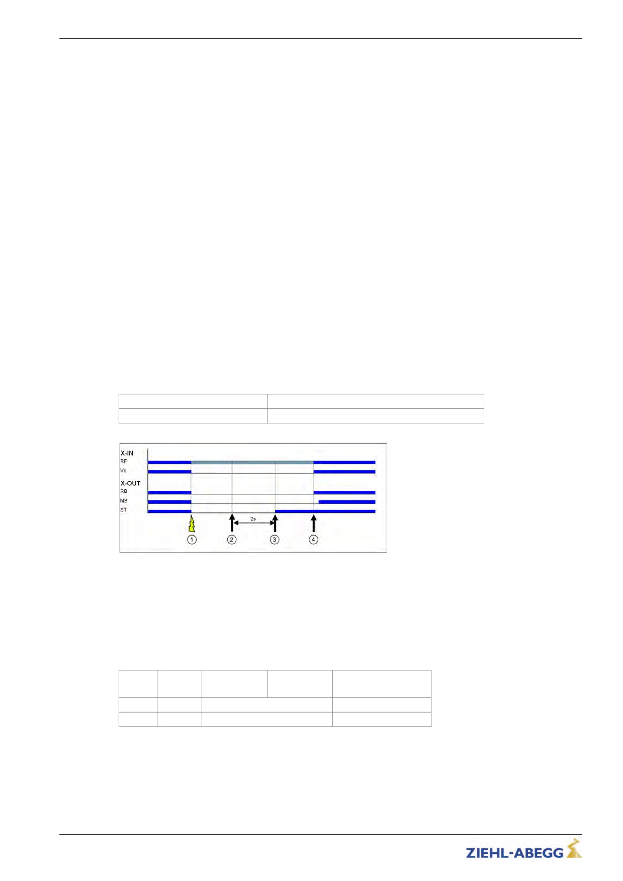
Error diagnosis
13
Error diagnosis
13.1
Travel abort and acknowledgement during malfunctions
13.1.1
Travel abort
If the frequency inverter detects an error, the actual travel program is aborted and following outputs
are switched off immediately:
• ST - Malfunction
• RB - Controller ready (motor contactors)
• MB - mechanical brake
The open loop control must immediately:
• Close the electromechanical brake
• Open the motor contactors
The machine is decelerated by the brake torque of the mechanical brake.
The error that has occurred is shown in the display with error text and error number. LED’s, error
memory and an error list are available for additional troubleshooting.
13.1.2
Acknowledgement
Acknowledging the error is performed automatically 2 seconds after the cause of the error has been
repaired.
The prerequisite is that the input signals for traveling speeds are applied. No error acknowledgement
is issued f traveling signals are applied before the expiration of the 2 seconds.
The following errors are not automatically acknowledged:
Error no.
Acknowledgement by
900 ... 999
Switch frequency inverter off and then back on
1
Error is recognized
2
Error is no more present
3
Atomatic acknowledgement with Vx=0
4
New travel command
13.2
Light emitting diodes
Condition of the frequency inverter
The four LEDs "Error (red)", "Update (yellow)", "Op1 (yellow)" und "Op2 (green)" are available to
diagnose the frequency inverter.
Error
Update
Op1 (gelb)
Op2 (grün)
Operation condition
(red)
(yellow)
Off
Off
Slow alternating flashing
Holding
Off
Off
Fast, alternating flashing
Travel
128/200
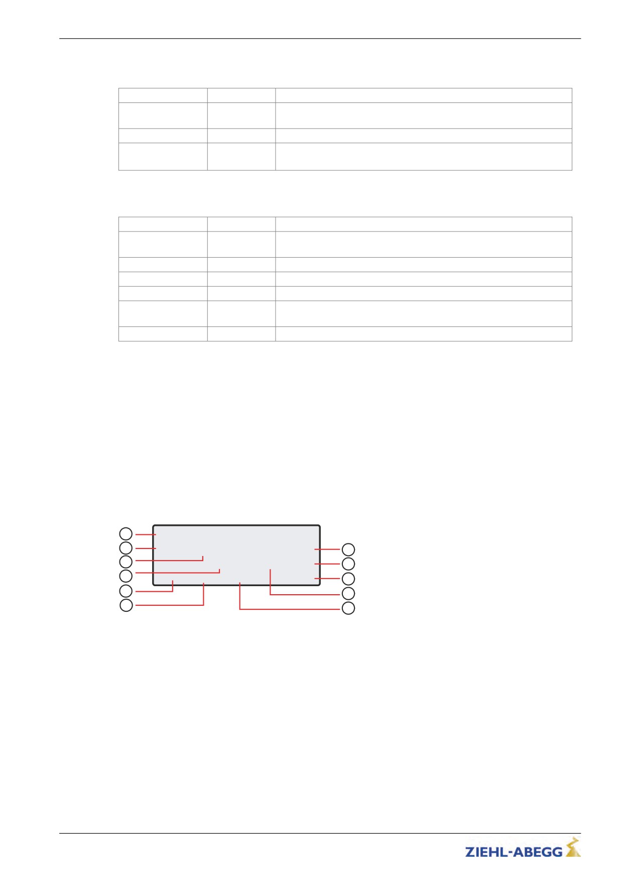
Error diagnosis
Condition of the DCP connection
The two LEDs "Error (red)" and "Run (green)" are available to diagnose the DCP connection.
LED
LED status
Operation condition
Error (rot)
fast flashing
With activated DCP function, the DCP connection is not present or is
defective
Run (grün)
On
With activated DCP function, the DCP connection is flawless
Error (rot) /
Slow alternat-
The DCP function is not activated in a trouble-free DCP connection
Run (grün)
ing flashing
(only DCP3/DCP4)
Condition of the CAN connection
The two LEDs "Error (red)" and "Run (green)" are available to diagnose the CAN connection.
LED colour
LED status
Operation condition / error status
Run (grün)
flashing once
Operation Mode "Stopped"
per second
Run (grün)
fast flashing
Operation Mode "Preoperational"
Run (grün)
on
Operation Mode "Operational"
Error (rot)
Off
no error, connection is in order
Error (rot)
flashing once
CAN error counter has exeeded the warning limit of 96 errors
per second
Error (rot)
On
Bus off, reset of the controller is necessary
13.2.1
Software update
If an error occurs during the software update, a flash code is issued by LED OP1 for the corresponding
error message.
An explanation of the flash code can be found in the chapter Special Functions/Software Update
13.3
Readout the error memory
Faults which lead to interruption of the travel are saved in a fault list.
The fault list can be found in menu Statistik/ST_LST. Up to 64 error messages can be managed.
Once the number of 64 messages has been reached, the oldest entry in each case is deleted for each
new error message which arises. When the fault list is called up, the last fault which occurred is
displayed with the following information:
1
? BR:Fahrt-Fehler
?
2
E583 S430
8.2h
7
3
0000076 xxx
28C
8
4
?00
RV1
5.91m
+12 A
9
5
10
6
11
1
Error description
2
Error no.
3
Operation condition (S=status)
4
Travel number
5
Consecutive error number
6
Travel direction
7
Operating hours
8
Temperture power stage
9
Motor current consumption
10
Additional information (option)
11
Position of tha car in the shaft
Please refer to the "Error diagnosis“ chapter for a description of the error number and the operating
condition.
129/200
Error diagnosis
The following information is displayed when the error list is opened and the
key is pressed
additionally:
1
? BR:Fahrt-Fehler
?
2
6
E583 S430
-1.6h
3
0000001 xxx
28C
7
4
S:Check MOP-status
8
5
1
Error description
2
Error no.
3
Operation condition (S=status)
4
Indication how many trips ago the error occurred
5
Status in which the error occurred is in plain text
6
Time how long ago the error occurred
7
Temperture power stage
8
Additional information (option)
Scroll through fault list:
the fault list can be scrolled through using the two arrow keys.
Scroll up (reduce fault serial number)
Scroll down (increase fault serial number)
Determine time of fault
When i key is pressed, the difference from the current number of
travels and operting time is displayed
" BC:Alarm/fault 3
E912 S422 -2.4h
-0000189 12C
" 01 RV1 0.00m +12A
In CANopen lift and DCP operation the time at which the error occurred is saved and displayed in the
error list.
? BR:Fahrt-Fehler
?
E583 S430
10:30
1
0000076 xxx
28C
? 00
RV1
5.91m
+12 A
1
Time at which the error occurred
13.4
Delete error memory
The fault memory is wiped by means of an entry in the Statistic/ST_CLR=ON.
The following parameters are reset:
• ST_LST (Error list)
• ST_RES (Number of interruptions in the mains supply)
• ST_SRF (Number of trip interruptions due to an interruption in the control enabling)
• ST_SCO (Number of trip interruptions due to an interruption in the contactor monitor)
130/200
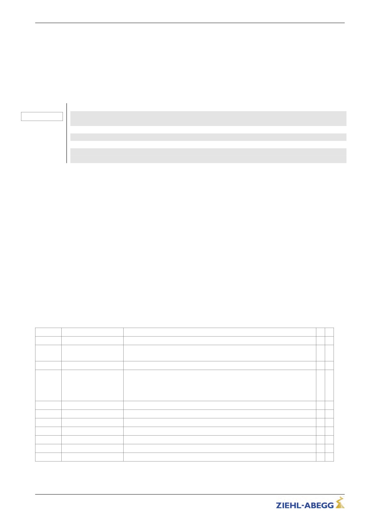
Error diagnosis
13.5
Error list
All error messages are stored in the Statistic / ST_LST menu (see "Error diagnosis / error memory"
chapter)
13.5.1
Masc-Funktion
You can deactivate individual monitoring functions by inputting an item in the error mask (see
"Parameter list/Monitoring" menu chapter). To do this, enter the corresponding error number into error
masks 1-5.
The maskable errors are marked in the error list with a point in thecolum n M.
Caution!
CAUTION!
Never use the mask function during trouble shooting and error diagnosis. You must acknowl-
edge the cause of the error for permanent inverter operation!
Sequential errors can occur if errors are masked.
The masking deactivates important monitoring functions. This may result in dangerous operat-
ing states or damage to the inverter.
13.5.2
Block function
Blocks the controller if certain errors occur several times is succession. The errors must occur in
directly consecutive travel tests. The fault counter is set to 0 when performing a trouble-free run.
The following block functions can be set in the Monitoring / MOD_ST menu:
• Fix 2 Sec.: No blocking function, the output configured on "ST" drops for 2 seconds during a
malfunction and then increases again (speed preset V_x must be switched off)
• Lock n.3: Lock function after 3 malfunctions. Output "ST" remains dropped after the 3rd error
• Lock n.2: Lock function after 2 malfunctions. Output "ST" remains dropped after the 2rd error
• Lock n.1: Lock function after 1 malfunction1. Output "ST" remains dropped after the 1st error
Errors that lead to a blocking of the frequency inverter are marked with a point in column S.
13.5.3
Notes 0xx
Information about:
• Error memory content
• Changes in the operating conditions
• Application of special inverter functions
Note-No.
Note text
Description
M
S
N0
Memory empty
EEPROM is empty
N010
Software update
Software update was carried out
Additional information: Version of the new software
N020
MOT_TYP changed
Motor type in "Motor name plate" was changed
N077
ST_LST: locked
Five faults occurred in direct succession
●
Fault memory is blocked
Additional information: indicates the most recent fault
The fault counter is set to 0 when performing a trouble-free run.
N080
Mode: EVA ->Norm
Switchover from evacuation to normal mode was implemented
N081
Mode: Norm ->EVA
Switchover from normal to evacuation to mode was implemented
N082
Mode:ParaChange
The parameter set was changed
●
N085
Mode: Safety Br
Safety brake function was implemented
●
N086
Mode:Enc.Adj.MB
Encoder-alignment with closed brakes was carried out
N087
Mode:Encoder-Adj.
Manual encoder offset was carried out
N088
Mode:Encoder-Check
The encoder offset alignment was checked
131/200
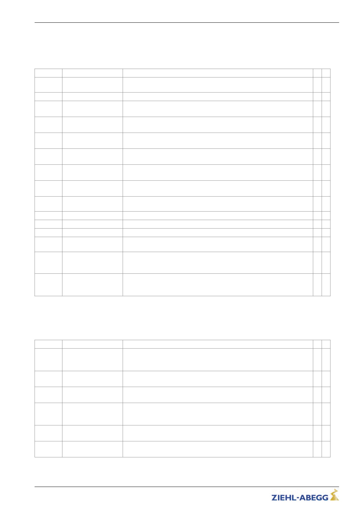
Error diagnosis
13.5.4
Error 1xx
• Hardware configuration error
• Software error
Error no.
Error text
Error cause
M
S
Inverter / CU does not have a serial number, e.g. after a component replace-
●
100
Serial no. missing
ment
101
System-Error
An internal, defective component was found during a self-test of the inverter
●
110
CU ID no. was not detected:
●
CU: No ID
120
CU is not present or its ID EEPROM does not reply
Shunt ID no. was not detected:
●
111
CUSH: No ID
Shunt module is not present or its ID EEPROM does not reply
ID No. of the extension card for the encoder is not recognized: extension
●
113
CUEE: No ID
module is not present or its ID EEPROM does not reply
123
115
Switching power supply ID no. was not detected: Switching power supply is not
●
SP: No ID
present or its ID EEPROM does not reply
125
116
Power print ID no. was not detected:
●
PP: No ID
126
Power print is not present or its ID EEPROM does not reply
117
The print module ID no. was not detected:
●
MP: No ID
127
Module Print is not present or its ID EEPROM does not reply
Internal shunt module was detected but there are problems with the shunt
●
121
CUSH: ID-Error
module's informational content
140
MP:Unknown IGBT
A unknown IGBT-module was recognized
141
MP: Temp.Sens?
The external temperature sensor for the Modul Print is not recognized
●
150
HW-Conflict !
Shuntmodul, Power Print and Modul Prind do not match
Frequency converter type ZETADYN 3-HY is not equipped with an analogue
●
155
No Analog-Input!
input (X-AN)
Option module for the temperature monitoring of the motor is nit recognized:
●
174
CUMT:Not detect
Check the configuration for rhe temperature monitoring in the "Monitoring"
menu
Error: DCP2 or DCP4 is entered for the communication between inverter and
●
elevator contol. This is not possible with Open-Loop-operation
180
UF CTRL=DCP2/4
Remedy: Enter DCP1 or DCP3 for the communication
13.5.5
Error 2xx
• Configuration error
Error no.
Error text
Error cause
M
S
Error: A parameter is open while apply a correct travel command (RF + RVx +
●
Vx)
200
Stop input
Remedy: End parameter inputs
Error: a parameter in the "Motor name plate" menu has not been assigned
201
Motor name plate
Remedy: Check the parameter in the "Motor name plate" menu,
Error: No motor type was selected in the "Motor name plate" menu
●
202
MOT_TYP = ?
Remedy: Enter in the "Motor name plate"menu
Error: No speed was entered in the "Installation" menu
●
203
n* = 0?
Remedy: Enter the speed at V* in the "Installation" menu directly or have it
calculated based on the installation data
Error: n* was incorrectly calculated due to incorrect installation data (n* >3xn)
●
204
n* > 3*n
Remedy: Check the installation data for correct entry
Error: two digital inputs are assigned with the same function
●
205
Input duplicated
Remedy: Change the function allocation of the digital inputs
132/200
Error diagnosis
Error no.
Error text
Error cause
M
S
Fault:When using a feedback unit in connection with a brake resistor the
●
temperature monitor of the brake resistor is not programmed
207
Input PFU_BR miss.
Remedy: Parameterise digital input (preferably X_BR4) in the "Control" menu
to the "PFU_BR" function
Error: Emergency stop was done by deactivating of the input with the function
"/DELAY"
208
DELAY active
At travel start, the input with the function "/DELAY" is not active
Remedy: Check the triggering of the input with the function "/DELAY"
Error: Encoder type and motor type do not match
●
●
210
Wrong ENC_TYP
Remedy: Enter the correct encoder type in the "Encoder & BC"menu
Error: With theb encoder types TTL-sine wave or EnDat/SSi no binary resolu-
tion was enterd
211
No binary encoder
Remedy: Enter a binary resolution (e.g. 512, 1024 or 2048)
ZR_EN /ZR_RDY miss-
Error:"ZR_RDY" or "ZR_EN" was not configured
213
ing
Remedy:Set digital input to "ZR_RDY" or set digital output to "ZR_EN"
Error: While operating synchronous motors, the values for the rated speed (n)
●
●
and the rated frequency (f) do not match in the "Motor name plate" menu
220
Error: SM data
Remedy: Enter the correct data for rated speed and rated frequency in the
"Motor name plate" menu
Error: While operating asynchronous motors, the values for the rated speed
●
●
(n) and the rated frequency (f) do not match in the "Motor name plate" menu
221
Error: ASM data
Remedy: Enter the correct data for rated speed and rated frequency in the
"Motor name plate" menu
Error: the limit value configured for V_G1 is too large
231
V_G1 > 150% V*
Remedy: Configure the limit value V_G1 to max 150% V* in the "Control
system" menu
Error: the limit value configured for V_G2 is too large
232
V_G2 > 150% V*
Remedy: Configure the limit value V_G2 to max 150% V* in the "Control
system" menu
Error: the limit value configured for V_G3 is too large
233
V_G3 > 150% V*
Remedy: Configure the limit value V_G3 to max 150% V* in the "Control
system" menu
Error: At start of travel, no signal present at the digital input set to "ZR_RDY"
Remedy: Check wiring
240
ZR:Not RDY
Use the ZArec display to check for an error at the ZArec
Exit ZArec configuration level
Error: Information travel direction change counter
270
Cable change warning
Replacement of the cables in about 1 year
Error: the calculated deceleration path S31 is too long
●
280
S31 too long
Remedy: in the "Decelerate" menu, increase the deceleration "A_NEG" or
reduce the round offs "R_NEG1" and "R_NEG2
Error: V* in the "Installation data" menu has not been assigned
285
Installation:V*=0
Remedy: Check the parameter in the "Installation" menu
Error: One of the travelling speeds V_1 ... V_7 entered is larger than the
entered rated speed V*
287
V1 . . . V7 > V*!
Remedy: Configure speeds V_1 … V_7 in the "Travel" menu to ≤ V*
Error: The traveling speed V_3 entered is larger than the entered rated speed
●
●
V*
288
V_3 > V*
Remedy: Set speed "V_3" in the "Travel" menu to ≤ V
Error: Speeds in the "Travellingl" menu are incorrectly set
●
●
289
V_1 < V_2 < V_3!
Remedy: In the "Travel" menu, make sure that V_1 < V_2 and V_2 <V_3
Error: Activated parameter set 2 does not contain any data
●
290
ParaSet2 empty!
Remedy: In the "Parameter set 2" menu, copy the the data from parameter set
1 to parameter set 2
133/200
Error diagnosis
13.5.6
Error 3xx
• Error before trip start
Error no.
Error text
Error cause
M
S
Error: No communication between the application processor and the motor
●
●
301
MOP: Timeout
management processor during start due to an error during the update
Remedy: Perform a software update
Error: Software error message in the motor management processor
●
●
303
MOP: SW-Error
Remedy: Perform a software update
304
MOP: HW-Error
Error: Hardware error message in the motor management processor
●
●
Error: Zero point offset in the motor current detection (analogue digital con-
●
305
verter) is outside the tolerance
ADC calibration??
306
Remedy: Replace defective shunt module
Error: Defective current measuring the phase U, V or W
●
●
307
Iu Iv Iw > 1.0A
Remendy: Check the connector of the Shunt-Modul
Current sensors are defekt
Error: The connected absolute encoder is not detected (when switching on the
●
inverter no the absolute encoder was not connected)
310
No abs.enc
Remedy: Check encoder connection
Switch frequency inverter off and then back on
Parameter im Menü "Encoder & BC" überprüfen
315
EnDat: HW-error
Error: EnDat encoder delivers error
●
Error: Configured resolution in the EnDat encoder does not match the encoder
●
resolution
316
EnDat: Resolution
Remedy: Enter the correct encoder resolution in the "Encoder & BC" menu
Error: Configured sinusoidal encoder was not detected
●
●
320
ENC: Error-start
Remedy: Check connection
Check the encoder type; possibly connect a square wave encoder
Error: While starting, an error was read out from the EnDat encoder. Error is
stated as a code:
0: defective encoder power supply
1: no SSI communication
2: Encoder illumination defective
321
EnDat: ULP-error
3: defective signal amplitude
4: Positioning error
5: defective sine evaluation
Remedy: Check the connection, Check the encoder
Error: During start, malfunction in communication to EnDat encoder; absolute
value could not be read out
322
EnDat: Com-Fehler
Remedy: Check the encoder,
Check rotary encoder line
Check the encoder configuration in the "Encoder & BC" menu
Error: During start, malfunction in communication to SSI encoder; absolute
value could not be read out
Remedy: Check the encoder,
324
SSI: Ack-Error
Check rotary encoder line
Check the encoder configuration in the "Encoder & BC" menu
Error: During start, malfunction in communication to SSI encoder; absolute
value could not be read out, encoder does not reply
Remedy: Check the encoder,
325
SSI: Timeout
Check rotary encoder line
Check the encoder configuration in the "Encoder & BC" menu
Error: During reading out the position of the absolute encoder (position will be
read out repeatedly) different values will be read.
Remedy: Check the encoder,
327
ENC: Read-Error
Check rotary encoder line
Check encoder connection (e.g. shielding)
134/200

Error diagnosis
Error no.
Error text
Error cause
M
S
Error: Too large a difference between the position determined by the absolute
rotary encoder and the position calculated from the encoder pulses
Remedy: Check the encoder,
328
ENC: Count-Dif
Check rotary encoder line
Check encoder connection (e.g. shielding)
Fault: Plausibility between sine and cosine track of sinus encoder unsatisfac-
tory
Remedy: Check the encoder,
329
ENC:Sinus-Error S
Check rotary encoder line
Check encoder connection (e.g. shielding)
Fault: Plausibility between sine and cosine track of sinus encoder unsatisfac-
tory
Number of checks can be set in the menu "S9_ZA-Intern/ENC_C HK". The
factory setting ENC_CHK=4 corresponds to a check duration of approx. 1 ms.
330
ENC:Sinus-Error F
Remedy: Check the encoder,
Check rotary encoder line
Check encoder connection (e.g. shielding)
Error: Start-Bit of the EnDat-protocol is not detected
Remedy: Check the encoder,
331
ENC: Error NDEF
Check rotary encoder line
Check encoder connection (e.g. shielding)
Fault: input voltages of signal tracks C and D of absolute value encoder type
ERN1387 areboth zero
Remedy: Check the encoder,
332
ENC: 1387 CD=0
Check rotary encoder line
Check the encoder connection
Error: Before starting to move, no absolute value can be read in from encoder
●
372
ENC:No Abs.value
Remedy: Check encoder connection
Error: Before starting to move, no absolute value can be read in from encoder
●
373
ENC:No Abs.End
Remedy: Check encoder connection
Fault: with parameterised motor temperature monitor "P1P2=PTC" the resist-
●
ance at the input P1P2 is < 20 ohms
Remedy: Check connected motor temperature monitor
374
P1P2:short-circuit
Check parameterised sensor type in "Monitoring/P1P2" menu
Short-circuit at the X-MT:P1P2 is not permissible
Fault: motor temperature monitoring has responded at a standstill
●
●
375
MOT:Temp.warning
Remedy: Check the temperature sensor connection
remove the cause for the rise in the motor temperature
Error: The continious braking power of the Brake resistor is exceeded by
●
●
150 % within 120 s
377
BRxx:Temp.warning
A restart will be avoided
Remedy: Check the configuration of the BR-type
Check the connected BR
378
MP: Not active!
Fault: Mains supply of the power section not active
●
Error: during startup, the temperature on the power stage is too high
●
●
379
MP:Temp.warning
Remedy: Inverter is overloaded,
repair the cause for the overload
Error: When the brake monitoring is activated, at least 1 brake monitoring
●
contact is not connected or is incorrectly connected
Remedy: Check the functioning (NO or NC) in the monitoring contacts,
380
BR: Start-Error
check the configured number and function of the monitoring contacts in the
"Monitoring" menu,
check the connection of the monitoring contacts
Error: Inverter has not received any initialization data from the open loop
●
control (in DCP03 & DCP04)
Remedy: Check the DCP line connection,
385
DCP: Init fail
Check the type of triggering control in the "Control system" menu
Check the elevator control system
135/200
Error diagnosis
Error no.
Error text
Error cause
M
S
395
MP:ERR_EXT active
Error: Internal defect of the device, overcurrent in the power stage
●
●
13.5.7
Error 4xx
• Trip abort to protect the frequency inverter
• Voltage monitoring
• Overvoltage Brake resistor / Brake-Chopper
• Power stage temperature recording
• Current monitoring
Error no.
Error text
Error cause
M
S
ADC: Over current!
Error: Maximum modulation of the analogue current converter, motor current
●
too high
Remedy: Check the connection to inverter output for short-circuit,
check encoder connection for connection of encoder tracks,
410
check the phase position (URU; VRV; WRW),
Check motor data in the "Motor name plate" menu,
Decrease "SPD_KP" amplification in the "Control system" menu,
Reduce amplification during start "K_START" in the "Start" menu
412
MOT:UVW fail
Error: Motor test current not correct
●
Remedy: Check the motor connection
Check the motor contactors
(see also "Special functions" chapter)
415
MOT: Current UVW
Error: Motor fault current, earth fault
●
●
Remedy: Check the motor connection
Check the encoder connection
420
MP: Temp. Fault
Error: Excess heat in the power stage
●
●
Remedy: Check the fan,
check the ambient temperature,
when installing the inverter in the switch cabinet, ensure it has sufficient
ventilation
431
MP: PWM fail
Error: The pulse width modulation of the clock frequency is not switched on or
●
●
off
Remedy: Check encoder connection
450
MP: Overload!
Error: Nominal current of inverter exceeded by a factor of 1.8 for 10 s
●
Remedy: Check motor data
Check calculation
Check the weight compensation
460
HY_OVERLOAD
only at ZETADYN 3-HY
●
Fault: Maximum level of the internal current controllers
Remedy: Check motor data
Check encoder type
Check the encoder connection
Check encoder resolution
Reduce machine speed
Check machine for overload
Info: inverted Function
470
DC: U < UDC_MIN
Error: Intermediate circuit has undercut the permissible value for "UDC_MIN"
●
●
(Menu "Power section") during travel
Remedy: Check the setting for the "UDC_MIN! value in the "Power section"
menu,
check the inverter size,
Check the motor data
Voltage drop during the travel
Check the input phases
136/200

Error diagnosis
Error no.
Error text
Error cause
M
S
471
DC: U > UDC_MAX
Error: Intermediate circuit has undercut the permissible value for "UDC_MAX"
●
●
(Menu "Power section") during travel
Remedy: Check the setting for the "UDC_MAX! value in the "Power section"
menu,
Check the connection / functioning of the brake chopper / brake resistor
Parameter im Menü "Encoder & BC" überprüfen,
Check the size of the Brake-Chopper / Brake-Resistor,
475
DC: U > 850 V
Error: During travel, the intermediate circuit voltage exceeds 850 VDC
●
Remedy: Check the connection / functioning of the brake chopper / brake
resistor,
Check the size of the Brake-Chopper / Brake-Resistor,
Check selection of brake chopper / brake resistor in chapter "Encoder &
BC/BC_Type"
480
MP: Overcurrent!
Error: In one motor phase, overcurrent was measured
●
Remedy: Check the motor connection (short-circuit, earth fault),
Check the encoder connection
Check the "SPD_KP" parameter in the "Control system" menu,
481
MP: Overcurr. CO
Error: in at least 1 open motor contactor monitoring-contact (contactor monitor
●
on X-CO not triggered), overcurrent was measured in one motor phase
Remedy: Check the contactor monitoring
Check the contactor wiring
490
MP: UCE -Alarm
Error:The IGBT monitoring was activated due to high motor current
●
Remedy: Check the motor connection (short-circuit, earth fault),
Check the encoder connection
Check the "SPD_KP" parameter in the "Control system" menu,
491
MP: UCE -Alarm CO
Error: in at least 1 open motor contactor monitoring-contact (contactor monitor
●
on X-CO not triggered), the IGBT monitoring was activated due to high motor
current
Remedy: Check the contactor monitoring
Check the contactor wiring
137/200

Error diagnosis
13.5.8
Error 5xx
• Trip abort to protect the installation
• Speed monitoring
• Contactor control
• Monitoring of Brake resistor / Brake-Chopper
• Motor temperature monitoring
Error no.
Error text
Error cause
M
S
501
Travel at MB=OFF
Error: Machine moves with deactivated MB output occurs if the brake is
●
●
opened manually
occurs if the brake is opened manually,
Remedy: Check the brake functioning
502
ENC:Sin-Enc.fail
Error: In standstill, a sine signal from the encoder was detected
●
●
Additional information: The maximum output voltage of the inverter was
reached at the time of the error
Remedy: Check the brake functioning
Check the encoder connection
503
No starting
Error: No encoder signal was received after expiration of the time T_GUE
●
●
(T_GUE is started with T_2)
Remedy: Check the function of the encoder,
Check the encoder connection
Check the brake lifting
Check the time "T_ENC" in the "Monitoring" menu
Check the times "T_2" and T_3" in the "Start" menu
504
ENC: Sig.Int.
Error: At target speed of >10 cm/s, inverter does not receive an encoder signal
●
●
Remedy: check motor connections (U R U; V R V; W R W),
Brake not closed during start,
Check the motor data
Check the encoder connection
Increase the "SPD_KP" parameter in the "Control system" menu,
505
MB/ENC fault
Error: At target speed of >10 cm/s, inverter does not receive an encoder
●
●
signal
Additional information: Motor current in ampere
Remedy: check motor connections (U R U; V R V; W R W),
Brake not closed during start,
Check the motor data
Check the encoder connection
Increase the "SPD_KP" parameter in the "Control system" menu,
506
X_ENC15:Discon.
Error: Interruption of the encoder signal during travel
Remedy: Check encoder connection
Switch frequency inverter off and then back on
515
v
> 110% V*
Error: Actual speed is ≥ 110% of the nominal speed V*
●
●
Remedy: Check whether the car counterweight is pulling up,
Check motor data in the "Motor name plate" menu,
Check the resolution type in the "Encoder & BC" menu,
Check the "SPD_KP" parameter in the "Control system" menu,
516
v > 150% V*
Error: Actual speed is ≥ 150% of the nominal speed V*
●
●
Remedy: Check whether the car counterweight is pulling up,
Check motor data in the "Motor name plate" menu,
Check the resolution type in the "Encoder & BC" menu,
Check the "SPD_KP" parameter in the "Control system" menu,
518
Speed too low
Error: The actual speed deviates from the target speed by -15%
●
●
519
Remedy: Check encoder connection
Check the encoder impulses in the "Info" menu, page 11,
Check the brake lifting
Check motor data in the "Motor name plate" menu,
Check the resolution type in the "Encoder & BC" menu,
Increase "SPD_KP" amplification in the "Controller" menu
138/200

Error diagnosis
Error no.
Error text
Error cause
M
S
520
Wrong direction
Error: Machine moves more than 12 cm in the wrong direction
●
●
Remedy: Check encoder connection
Check the encoder configuration in the "Encoder & BC" menu
check the motor connections (URU; VRV; WRW)
Inverter size too small
522
ENC: Dif. Pos
Error: Too large positive difference in the encoder counter level between two
●
●
scan steps. The limit value equals 2 times the installation rated speed
Remedy: Check whether the car counterweight is pulling up,
Check motor data in the "Motor name plate" menu,
Check the resolution type in the "Encoder & BC" menu,
Check the "SPD_KP" parameter in the "Control system" menu,
Check the motor connection
523
ENC: Dif. neg
Error: Too large negative difference in the encoder counter level between two
●
●
scan steps. The limit value equals 2 times the installation rated speed
Remedy: Check whether the car counterweight is pulling up,
Check motor data in the "Motor name plate" menu,
Check the resolution type in the "Encoder & BC" menu,
Check the "SPD_KP" parameter in the "Control system" menu,
Check the motor connection
525
ENC: 1387 ADC Limit
Fault:signal track A or B of the absolute value or sinus encoder exceeding
●
●
permitted limit value during travel
Fault entry not made until end of travel
Travel not cancelled
Remedy: Check the encoder,
Check the optional PCB for encoder connection,
Check the rotary encoder type in the "Encoder & BC" menu,
529
Quickstart alarm
Error: During a quick start function, the machine moves more than 7 mm while
●
●
input "V=0" is triggered
Remedy: Check the parameter in the "Motor name plate" menu,
Shorten time during which input "V=0" is triggered,
check the motor connections (URU; VR V; WR W)
535
ZR:RDY abort
Error: The signal at the digital input set to "ZR_RDY" drops out during travel
Remedy: Use the ZArec display to check for an error at the ZArec
540
CO: ON!?
Fault: No signal is available at the end of the contactor monitoring time
●
T_CDLY
Remedy: Check the wiring of the contactor monitoring,
check wiring the contactor control
check the power supply of the motor contactors ,
Check the power-supply of the contactor monitoring,
Check contactor switch-on time "T_CDLY " in the "Monitoring" menu,
Check the contactor monitoring in the "Monitoring" menu
Info: In case of a contactor monitor break, the inputs that triggered the error
are displayed in the "Additional information" field (1: CO1, 2: CO2, 3: CO1 and
CO2).
544
CO/RF:Vx activ!
Error: 300 ms after switching off the digital outputs RB and MB due to a RF- or
●
CO-interrupt, the travel comands of the elevator control are still activated
Remedy: Check the analysis of the output signals from the inverter by the
elevator control
545
CO open early
Error: Motor contactors are open during travel
●
Remedy: Check the motor contactor triggering
Check the safety circuit
Info: In case of a contactor monitor break, the inputs that triggered the error
are displayed in the "Additional information" field (1: CO1, 2: CO2, 3: CO1 and
CO2).
546
CO: open early M
Error: Motor contactors are open during travel
●
Remedy: Check the motor contactor triggering
Check the safety circuit
139/200

Error diagnosis
Error no.
Error text
Error cause
M
S
548
CO1: still on
Error: 5s after expiration of T_CDLY, a signal is still present on the contactor
●
monitor input CO1
Remedy: Check the wiring of the contactor monitoring,
check wiring the contactor control
549
CO12: still on
Error: 5s after expiration of T_CDLY, a signal is still present on the contactor
●
monitor input CO1 or CO2
Remedy: Check the wiring of the contactor monitoring,
check wiring the contactor control
Info: In case of a contactor monitor break, the inputs that triggered the error
are displayed in the "Additional information" field (1: CO1, 2: CO2, 3: CO1 and
CO2).
550
MOT: Overload !
Error: Motor current exceeds the value max for time Tmax
●
●
Remedy: Check the parameter in the "Motor name plate" menu,
Check the weight compensation
Check the brake switching function
560
V > VZ
Error: Actual speed exceeds the specified nominal speed for readjustment
●
when readjusting.
Info: inverted Function
Error is displayed if entered in mask
At CONFIG: 31:KL_IO the function is entered in the mask automatically.
570
PFU Alarm
Error: Monitor contact of the power feedback unit opens during operation of
●
the ZETADYN
Remedy: Check connection of the feedback unit function monitor,
Check function monitor of power feedback unit,
Check the function of the power feedback unit
The error is automatically acknowledged when the monitor contact of the
power feedback unit reconnects.
571
PFU:Stdby remains in
Error: PFU is not yet active 1 s after start of travel
●
place
575
MOT: Temp. -Alarm
Error: Motor temperature monitor triggered during the trip (error evaluation
●
●
only if error no. 575 is entered in the mask function)
Remedy: Check the parameter in the "Motor name plate" menu,
check the motor's duty cycle,
check the motor for winding short,
check the encoder,
Check the brake function
582
BR:T2 too small
Error: Brake does not open within time T2 (only active if brake monitor is
●
switched on)
Remedy: Check the brake triggering,
check the brake opening time,
check the configured brake opening time "T_2" in the "Start" menu and
increase if necessary
583
BR: Fault Travel
Error: Brake monitoring contacts triggered during travel
●
●
Remedy: Check the brake triggering,
check the monitoring contacts,
check the power supply of the brakes
Information:
• Negated function: If entered in the mask, the error leads to immediate stop of
travel
• Error does not lead to blocking of the ZETADYN with parameter LOCK-
BR="ON"
140/200

Error diagnosis
Error no.
Error text
Error cause
M
S
584
BR: Fault Travel
Error: Brake monitoring contacts triggered during travel
●
●
Fault message at end of travel with additional information = 0:
Brake monitor contacts have switched during travel but the brake was not
closed
Fault message without immediate interruption of travel and additional informa-
tion ≠ 0:
Brake was closed during travel
Additional information: Indicates consequential fault
Remedy: Check the brake triggering,
check the monitoring contacts,
check the power supply of the brakes
Information:
Error does not lead to blocking of the ZETADYN with parameter LOCK-
BR="ON"
585
BR: T5 too small
Error: Brake does not close within time T5 (only active if brake monitor is
●
switched on)
Remedy: Check the brake triggering,
check the brake closing time,
check the configured brake opening time "T_5" in the "Stop" menu and
increase if necessary
586
BR: Stop-Error
Fault: Monitoring contact of the brake briefly signals "Brake closed and then
"Brake open" again longer as the time T5 (only active with the brake monitor
switched on)
Remedy: Check the brake triggering,
check the brake closing time,
check the configured brake opening time "T_5" in the "Stop" menu and
increase if necessary
590
RV1/RV2:Change
Fault: Change the direction specification during active travel
●
●
Additional information: Display of the set direction
1 = RV1
3 = RV2
Remedy: Check control of travel directions
13.5.9
Error 7xx
• Trip abort due to errors between frequency inverter and control system
Error no.
Error text
Error cause
M
S
710
DCP: Timeout
Error: DCP communication interrupted during travel
●
●
Remedy: check wiring (shields)
715
DCP: G0-G7 fail !
Error: Transmission error in the DCP protocol: Telegram for the speed preset
●
●
(G0-G7) not received
Remedy: Possibly the DCP-function of the elevator control is not compatible
720
DCP: Delay fail
Error: The DCP residual path increases during deceleration by more than 5cm
●
●
Remedy: Check the absolute rotary encoder for its residual path determination
Wrong residual path signal from open loop control
721
DCP: Dist. fail
Fault: There is no change in the residual path for 200 ms during the run
●
●
Remedy: Check the absolute rotary encoder for its residual path determination
Wrong residual path signal from open loop control
722
DCP: s_rest = 0?
Error: Residual path > 20mm jumps to 0mm
●
●
Remedy: Check the absolute rotary encoder for its residual path determination
Wrong residual path signal from open loop control
723
DCP: s_rest < 0!
Error: A negative residual path is transmitted during travel
●
●
Remedy: Check the DCP wiring
780
DCP: Quick Start >20s
Error: In the quick start function, input "V=0" is triggered for over 20s
●
●
Remedy: Shorten the time in which "V=0" is triggered
781
v0 at travel ?!l
Error: Input "V=0" is triggered during travel
●
●
Remedy: Check the triggering of "V=0"
141/200
Error diagnosis
Error no.
Error text
Error cause
M
S
799
RF:Failure
Error: Control enable RF was switched off during travel (error evaluation only if
●
●
error no. 799 is entered in the error mask)
Remedy: Check the triggering of "RF"
13.5.10
Error 8xx
• Errors which can occur in operation with CANopen Lift
If an error occurs during operation with CANopen, the frequency inverter runs through status "ST_De-
lay" and finally goes to status "Wait drivecom. off". At this status the frequency inverter waits until the
control system sends the command "Fault Reset".
Error no.
Error text
Error cause
M
S
800
CAN: Timeout
Errors in Velocity Mode:
●
Heartbeat from control system is missing or at wrong time.
Errors in Position Mode:
Heartbeat from control system and/or encoder is missing or at wrong time.
Adjustment:
Check CAN-connection
Check if devices have the right heartbeat.
810
CAN: Quick Stop Det.
Error:
Control system activates a quick stop.
820
CAN: Illegal Status
Error:
●
Control system sends commands in wrong order.
Adjustment:
Take care to the right order in CAN drive cycle
830
CAN: Timeout Enab.-
Error:
Det.
Control system gives command "Enable Operation" not within T_CMD
Adjustment:
Increase time for T_CMD
831
CAN: Timeout Dis. Op.
Error:
Control system gives command "Disable Operation" not within T_CMD
Adjustment:
Increase time for T_CMD
832
CAN: Timeout Shut-
Error:
down
Control system gives command "Shutdown" not within T_CMD. Occurs by
closing the brakes.
Adjustment:
Increase time for T_CMD
833
CAN: Timeout Dis. Vol.
Error:
Control system gives command "Disable Voltage" not within T_CMD. Occurs at
end of travel.
Adjustment:
Increase time for T_CMD
840
CAN: ENC. Info missing
Error:
The object "Encoder Info" was not written to the frequency inverter by the
control system
142/200
Error diagnosis
13.5.11
Error 9xx
• Fatal error, which can only be acknowledged by switching off the frequency inverter
Error no.
Error text
Error cause
M
S
905
MOP:HW-SW Error
Error: A hard- or software error occured after switching on the inverter. After
60s the inverter chabges to "Wait-Switch off"
Remedy:Check the connectors between the Control Unit and Modul Print
check the fuse on the Switching Power Print
no Modul Print existing
check EEprom on the Modul Print
906
ZR_ERR by start
Error: No signal at BC input during ZETADYN start-up
Remedy: Check wiring
Use the ZArec display to check for an error at the ZArec
908
PFU: No function
Fault:When switching on the converter, the monitor contact of the feedback
●
unit is not closed
Remedy: Check connection of the feedback unit function monitor,
Check function monitor of power feedback unit,
Check field of rotation of the mains connection for the power feedback unit
910
BC: No function
Error: When switching on the inverter, the monitoring contact for the Brake-
Chopper or Brake resistor is not closed
Remedy: Check the temperature monitor for the Brake-Chopper or Brake
resistor,
check the temperature monitoring for the Brake-Chopper or Brake-Resistor,
911
BRxx: Overload
Error: The continious braking power of the Brake resistor is exceeded by
●
150 % within 120 s
The inverter switches off during the travel
Remedy: Check the configuration of the BR-type
Check the connected BR
912
BC: Fault
Error: Monitoring contact for Brake-Chopper or Brake resistor opens while the
inverter is operating
Remedy: Check the temperature monitor for the Brake-Chopper or Brake
resistor,
check the temperature monitoring for the Brake-Chopper or Brake-Resistor,
913
DC: U_DC>U_BC
Fault: at a standstill, the voltage measured at the intermediate circuit (+DC/-
●
DC) after 5 s is higher than trigger voltage U_BC
Remedy: Defective analysis of the DC-link voltage U_DC
The synchronous motor is operated without motor contactors and driven by an
external load
914
X-ENC15:Miss.
Fehler:Bei Einschalten des Umrichters wird kein Geber an X-ENC 15 erkannt
Remedy: Check encoder connection
reset the inverter
916
X_ENC15:Discon.
Error: Interruption of the encoder signal during travel
Remedy: Check encoder connection
Switch frequency inverter off and then back on
917
BRxx activ
Error:The internal Transistor for the brake resistor is still triggered 5,5 s after
●
travel-end
918
MP:Temp.missing
Error: Temperature detector on power stage is not supplying any measure-
●
ments
Remedy: Change the device
Check fuse on SP board
919
ZR:ERR by opera.
Error: Signal at BC input drops out during travel
Remedy: Use the ZArec display to check for an error at the ZArec
920
MOP:ERRNMI active
Error: Overcurrent during standstill
●
Remedy: Check the brake chopper / brake resistor wiring
143/200
Error diagnosis
Error no.
Error text
Error cause
M
S
930
MP: UCE Alarm BR
Error: The voltage monitoring of the transistor of the Brake resistor has
●
triggered (Overcurrent of the electric circuit of the Brake resistor)
Remedy: Check wiring of the Brake-Resistor
Check Brake-Resistor
Check whether the correct type is configured in the "Encoder & BC/BC_Typ"
menu
931
MP:ERR_EXT active
Error: internal error message of the output stage
●
Remedy: Switch frequency inverter off and then back on
Replace the device (only after consulting the ZIEHL-ABEGG hotline)
950
TD_CNT: Drive Limit
Error: Number of maximum drives reached!
●
Only one travel with the actual rope remains.
Remedy: Change ropes and reset the down counter.
After resetting the ZETADYN 3 there is one additional drive possible.
991
MOP: Timeout
Error: The communication between the processors was interrupted or the
●
●
communication between the processors is faulty during travel.
Remedy: Make sure that the EMC regulations are observed (see chapter
"Electrical Installation / EMC-conform Installation")
994
MOP: Timeout 2
Error: I standstill the communication between the Motor-Management-Pro-
●
cessor (MOP) and the Application-Processor (APP) is interupped for more than
7.5 s
Increased BR-protection
995
ENC:1387 CD-Lim
Fault: signal track C and/or D of absolute value encoder type ERN1387
●
●
exceeds permitted limit value before travel starts
Remedy: Check the encoder,
Check the optional pcb for encoder connection
Fault can only be reset once the frequency inverter is switched off
13.5.12
Information texts
An information text appears in the display for approx. 2 s for faults which are not saved in the fault list.
Information text
Cause
CO-Interrupt
During a non distance-dependent travel (speeds V4 ... V7) the travel contactors are
opened.
During the halt process the motor contactors open before the timer T5b has expired.
The number of CO interruptions is counted in the Statistics/SCO menu.
RF-Interrupt
The controller enable (signal CE) is deactivated during travel.
During the halt process the controller enable (signal CE) is deactivated before the
timer T5b has expired.
The number of CE interruptions is counted in the Statistics/SCE menu.
s1 = 0 cm
During the distance-dependent delay phase from travelling speed V2 or V3 to position-
ing speed V1 the signal is already deactivated for the positioning speed V1.
Attention! n*>n
Calculated speed n* is greater than the speed n specified on the rating plate.
automatic
After changing the parameter V*, you can confirm the request " automatic pre-sign-
pre-signment?
ment?" with yes or no.
Until rope change
Shows the remaining travels with the actual rope.
xxx
Information will be shown in the display until pressing the [ESC] button.
travels possible
144/200
Error diagnosis
13.6
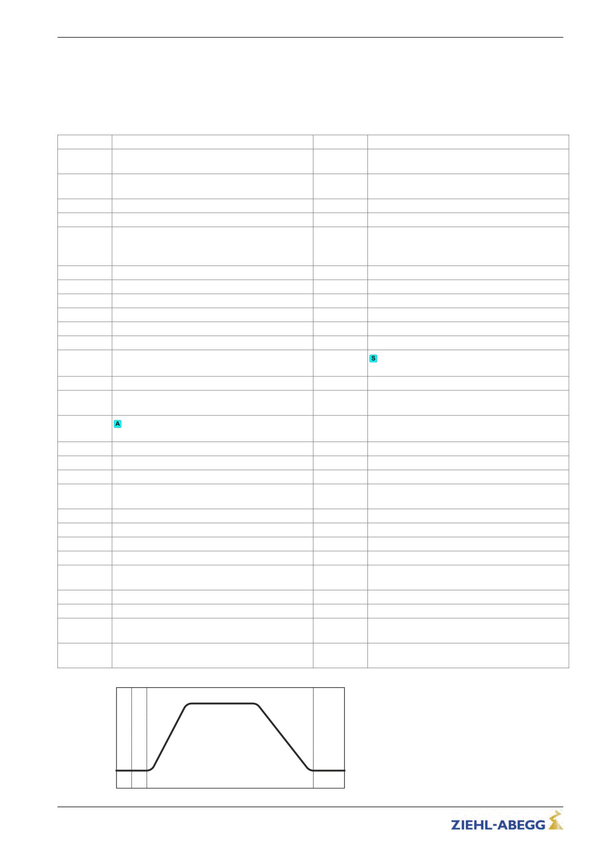
Operating conditions of the inverter
The frequency inverter software divides the operating curve into various sections. Each of
these sections is assigned a status number that refers to a defined service condition.
If an error occurs, the status number is stored with the error number in ther error list.
Furthermore, the operating conditions are displayed with the status number and in plain test in the
Info/Page02 menu.
status
Condition of the inverter
status
Condition of the inverter
Constant running at speed V3(time-dependent,
10
Checking of voltage supply
430
V1 is not activated)
Round down the acceleration to V3 (distance-de-
21
Check software version
431
pendent)
22
Parameter transmission
432
Linear acceleration to V3 (distance-dependent)
30
Check absolute value encoder
433
Constant travel with V3 (distance-dependent)
Check input BC
41
41: Power feedback unit
435
Deceleration with safety ramp
42
42: Brake chopper or brake resistor
50
Adjust current transformer
440
distance dependent travel with DCP4
70
Check temperature power unit
480
Retract to standstill
100
Device off
490
fast stop
105
Power feedback unit on standby
500
Keep motor at speed 0 (T4)
110
Machine ready
510
Wait until motor brakes are closed (T5)
200
Start-up check
515
Brake gets additional current feed for 1s
210 ... 223
Check absolute value encoder
520
Switch off current to motor (T5b)
300
Wait until motor contactors switched on (T0)
530
Wait until motor contactors switched off (T6)
Travel interrupted due to interruption of the con-
305
Checking the motor phases
535
troller enable RF
310
Travel interrupted due to interruption of the con-
536
311
Build-up of magnetic field in the motor (T1)
tactor monitor COx
320
Wait until motor brakes have opened (T2)
540
Wait for standstill
330
Accelerate motor to speed V_T3 (T3)
550
Checking the input BR after travel finished
340
Start up
560
End of travel
Delay of automatic acknowledgement after reme-
400
Accelerate to speed Vx
900
dying the cause of the fault (2 s)
402
Constant running at speed Vx
950
Parameter change
404
Delay from speed Vx
982
Motor type changed
410
Constant running at speed V1
988
Wait for reset
420
Constant running at speed V2
990
Fault input BC
Round down the acceleration to V2 (distance-de-
421
991
No absolute value encoder detected
pendent)
422
Linear acceleration to V2 (distance-dependent)
992
Temperature of the power section missing
423
Constant travel with V2 (distance-dependent)
997
Frequency converter is in stand-by mode
Rounding up and linear delay from V2 (distance-
424
998
Wait until frequency converter is switched off
dependent)
Rounding down of the delay from V2 (distance-
425
dependent)
2xx
3xx
4xx
5xx
Travel curve with related status numbers
145/200

Error diagnosis
13.7
Frequent startup problems
Problem
Cause
Adjustment
Frequency inverter does not start
Brake resistance is connected to
Brake resistance is connected to the
after switching on
the +DC and -DC terminals on ter-
+DC and R terminals on terminal X1/X3
minal X1/X3
Frequency inverter stands still in
Input voltage is too low
Check the input voltage of the inverter
status 40 during start procedure,
One phase on the line connection
Check wiring of the line connection
the fault message relay of output
is missing
O11-O14 does not pull up, the
menu cannot be operated
Motor does not reach nominal
Half load adjustment is not correct
Check half load adjustment and correct
speed (comparison of actual and
if necessary
nominal speed visible in the Info
Settings in the "Motor Rating Plate"
Check settings in the "Motor Rating
menu on page 04)
and "System Data" menus are not
Plate" and "System Data" menus (the
correct
value of the "n*" parameter in the "Sys-
tem Data" menu may not be much
greater than the value of the "n" param-
eter in the "Motor Rating Plate" menu)
Motor data are not correct
13.8
Automatic parameter check (APC)
The Automatic parameter check checks the input values for plausibility and tolerances while the
parameters are being entered.
The APC function aims to prevent erroneous parameter inputs. Every message must be acknowl-
key
You can activate or deactivate the APC function in the Monitoring/APC menu. The factory setting is
ON.
Monitoring
|-" APC
On
|-"
On
Auto.Parameter Control
Through the APC function:
• Values are restricted (Limit)
• Parameters are set (Set)
• Parameters are updated (Update). Parameters that are not preset are updated during a software
update.
13.9
Automatic parameter diagnostics (APD)
During Automatic parameter diagnostics, the following are checked:
• The parameters for plausibility and tolerances
• Device functions for functional errors
Erroneous parameters or functions are shown in the display.
key. The APD function can be activated
in the "Statistic/APD" menu. After checking, the function is reset to "OFF".
Statistics
|-" APD
OFF
|-"
ON
Automatic parameter
146/200
Energy saving
14
Energy saving
14.1
Stand-by function frequency converter
To save energy at standstill the frequency inverter ZETADYN 3 can be switched to stand-by mode.
Internal components of the frequency inverter are switched off in stand-by mode. This means that the
frequency inverter has a much lower power loss at standstill. There are two stand-by modes in the
ZETADYN 3:
• Standby 1
• Standby 2
14.1.1
Standby 1
In stand-by 1 mode the motor rotary encoder and the monitoring functions remain active, the output
relays remain switched on.
14.1.1.1
Activation of stand-by 1 mode
Information
Switching to stand-by mode is only possible when the controller enable (input CE) is switched off.
Configure digital input in theControl systemmenu toSTANDBY1.
Control system
|-" f_I08
STANDBY1
|-"
STANDBY1
Function of I_08
Activation of the STANDBY1 digital input:
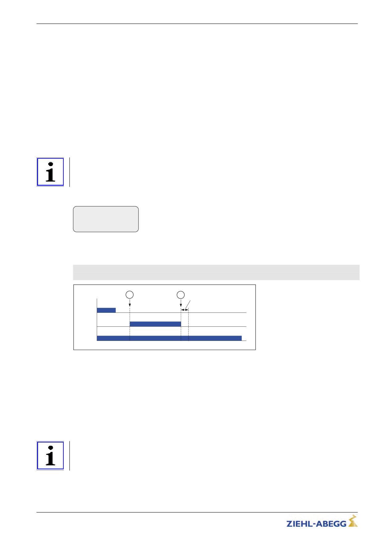
• Inverter switches to stand-by 1 mode
5 ms after deactivation of the digital STANDBY1 input the frequency inverter is ready for operation
again (see diagram).
1
2
5 ms
RF
STANDBY 1
ST
Function stand-by 1 mode ZETADYN 3
1
STANDBY1 input is activated
2
STANDBY1 input is activated
RF Controller enable
STANDBY1
Input with STANDBY 1 function
ST Err
14.1.2
Standby 2
In stand-by 2 mode the motor rotary encoder is switched off, the monitoring functions are not active
and all relays are switched off, including the fault message relay.
14.1.2.1
Activation of stand-by 2 mode
Information
Switching to stand-by 2 mode is only possible when the controller enable (input CE) is switched off.
147/200
Energy saving
Configure digital input in theControl systemmenu toSTANDBY2.
Control
|-" f_I08
STANDBY2
|-"
STANDBY2
Function I08
Activation of the STANDBY2 digital input:
• Inverter switches to stand-by 2 mode
• Output ST fault remains activated
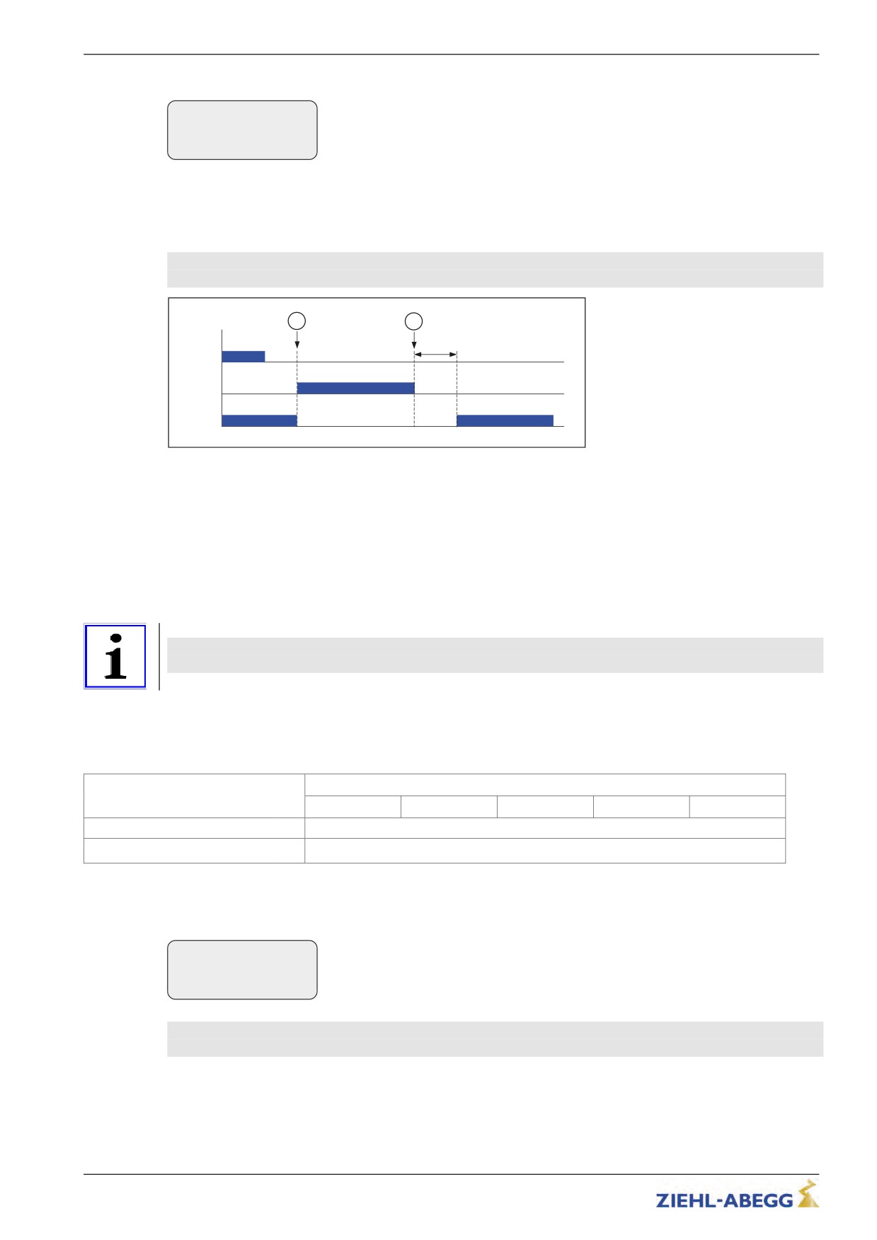
3 s after deactivation of the digital STANDBY2 input the frequency inverter is ready for operation
again. The ST fault output is activated (see diagram).
1
2
3 s
RF
STANDBY 2
ST
Function stand-by 2 mode ZETADYN 3
1
STANDBY2 input is activated
2
STANDBY2 input is activated
RF Controller enable
STANDBY2
Input with STANDBY 2 function
ST Err
14.2
Power Feedback Unit (PFU)
The power feedback unit offers the possibility to save energy by feeding the energy generated in a
generator run into the supply network. This energy is used by other consumers in the building.
Information
By using a power feedback unit graduation in energy efficiency class A according to VDI 4707
can be achieved!
14.2.1
Stand-by operation of the power feedback unit
To reduce the power loss of the power feedback unit at standstill the REVCON power feedback unit
can be switched to stand-by mode.
Revcon
SVC 07- 400
SVC 13 - 400
SVC 22 - 400
SVC 33 - 400
SVC 70 - 400
Power losses during standstill
[W]
24
Power loss in standby
[W]
8
14.2.1.1
Activation of stand-by mode
Parameterise digital output (preferably PWM) in the Control system menu to the PFU function.
Control system
|-" f_PWM
PFU
|-"
PFU
Function PWM
To switch the power feedback unit to stand-by mode the input A2 of the power feedback unit must be
disconnected from GND!
Deactivation of the digital output PFU:
• Power feedback unit switches to standby mode
148/200
Energy saving
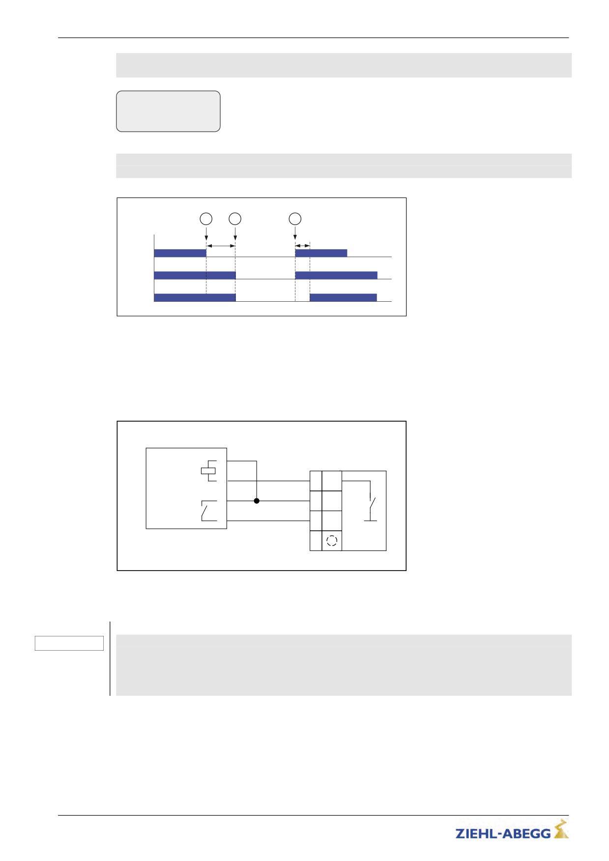
The time between the end of travel and activation of the PFU output can be specified with the
Encoder & BC/T_PFU parameter.
Encoder & BC
|-" T_PFU
0
s
If the parameter T_PFU is set to 0s , the output PFU is always active.
|-"
60
Standby is now deactivated.
Waiting time PFU PWM
1 s after deactivation of the digital output PFU the power feedback unit is ready for operation again
(see diagram).
1
2
3
T_PFU
1 s
RF
PFU
ST-Revcon
Function stand-by mode Revcon
1
End of travel
2
Output with the "PFU" function is activated
3
Output with the "PFU" function is deactivated
RF Controller enable
PFU Output with the "PFU" function
ST-Revcon Output "Fault" of the power feedback unit
14.2.1.2
Electrical connection stand-by mode
PFU
Revcon SVC
A1
X-BC
A2
(1)
PWM
X2
3
(2)
24V
4
(3)
BC
(4)
Connection Revcon power feedback unit with stand-by mode
14.2.1.3
Power feedback unit in connection with automatic emergency evacuation.
CAUTION!
In lift systems with automatic emergency evacuation by a single-phase mains supply (emer-
gency power supply unit/UPS) or battery (EVAC 3B) the power feedback unit is not active due
to the too operating voltage failure. To avoid too high a voltage in the intermediate circuit when
evacuating by a generator run, a brake resistor must be used in addition to the power feedback
unit!
149/200
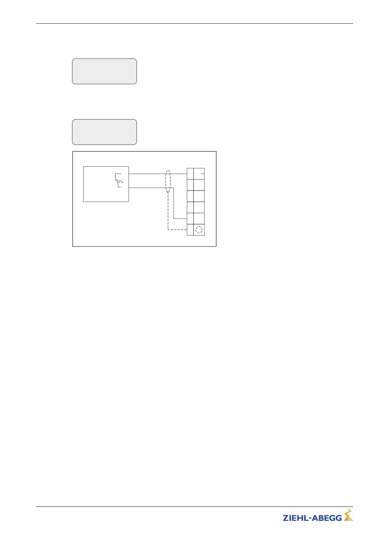
Energy saving
The combination power feedback unit + brake resistor must be entered in the Encoder & BC/BC_Typ
menu
Encoder & BC
|-" BC_TYP PFU+BR17
|-"
PFU+BR25
BR/BC type
Connection and parameterisation temperature monitor brake resistance
The temperature monitor is connected to a digital input (X-IN or X-BR). The input must be para-
meterised to the PFU_BR function.
Control
|-" f_XBR4
PFU_BR
|-"
PFU_BR
Function input BR4
X-BR
BR
+24 V
TB1
(6)
B
(5)
BR1
TB2
(4)
BR2
(3)
BR3
(2)
BR4
(1)
Connection brake resistor
150/200

Special functions
15
Special functions
15.1
Changing the Clock frequency
The factory setting of the frequency converter’s clock frequency depends on the size and the motor
type:
Size
Synchronous motor
Asynchronous motor
ZETADYN 3xx011
ZETADYN 3xx013
ZETADYN 3xx017
ZETADYN 3xx023
Clock frequency 16 kHz auto
Clock frequency 16 kHz auto
ZETADYN 3xx032
(Parameter M_PWM=Auto)
(Parameter M_PWM=Auto)
ZETADYN 3xx040
ZETADYN 3xx050
ZETADYN 3xx062
ZETADYN 3xx074
Information
If necessary the clock frequency can be changed continuously between 2.5 …. 16 kHz in the
Power section menu.
must be pressed for approx. 5 s. until ZIEHL-ABEGG-Intern FREIGABE
appears in the display.
Information
Only change the clock frequency after consultation with the ZIEHL-ABEGG hotline. Consulta-
tion can clarify the effect of changing the clock frequency on the service life of the frequency
inverter.
Caution!
Increasing the clock frequency causes
CAUTION!
• a performance reduction of the frequency inverter (see Technical Data chapter)
• a greater power loss and thus increased heating of the frequency inverter
The service life of the frequency inverter is negatively influenced by the higher temperatures.
15.1.1
Fixed presetting of the clock frequency (Menu Power sectionl/M_PWM=Fix f_PWM)
The cycle frequency of the frequency inverter is 8 kHz after setting at the factory. This can be
changed, if necessary, in the Power Unit/f_PWM menu continuously between 2.5 ... 10 kHz.
15.1.2
Automatic adjustment if the clock frequency (Menu Power sectionl/M_PWM=Auto)
The inverter works with the clock frequency which is configured in the the enu
Power section/f_PWM_H.
If required the inverter switches to the switching frequency set in the menu "Power section/f_PWM".
15.2
Encoder offset-alignment
Caution!
CAUTION!
Make sure you perform an encoder alignment if you operate a synchronous motor. Operating
the motor without encoder-offset alignment can cause uncontrolled motor movements.
Traveling is prohibited before an absolute encoder offset alignment has been performed!
Information
In ZIEHL-ABEGG motors, the absolute value encoder is already calibrated to the offset value
"0" ex works.
It is no longer necessary to perform an absolute encoder offset alignment!
151/200
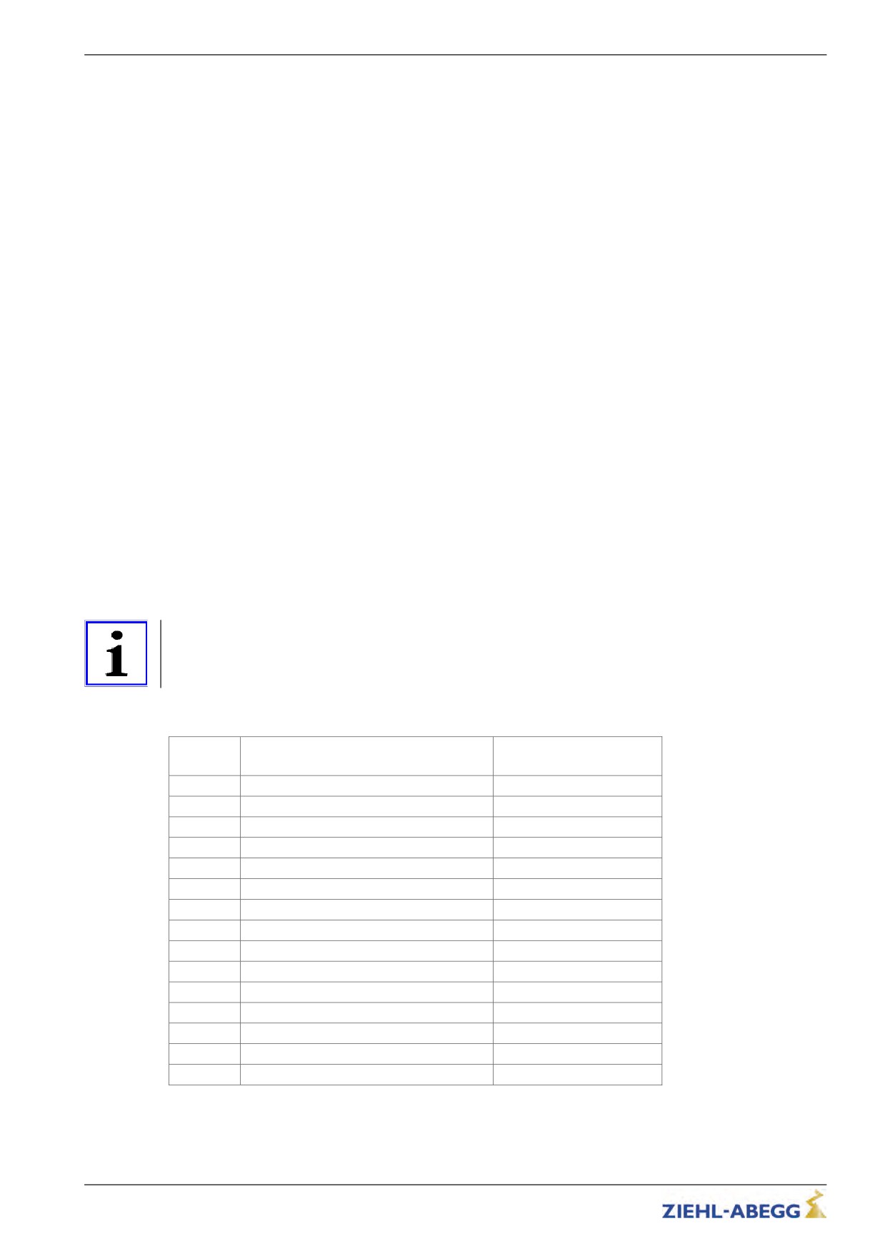
Special functions
Options for calibrating an absolute value encoder
The frequency converter ZETADYN 3BF has two different methods of calibrating the absolute value
encoder:
• load-free calibration of theabsolutevalue encoder
• calibration of the absolute value encoder with brake closed
General conditions required for an encoder alignment without load:
• The installation and motor data must be configured
• Load-free operation (ropes must be removed from the traction sheave)
• Brake monitoring must be activated corresponding to the number and type of brakes in use (
Monitoring/BR menu)
• Contactor monitoring must be configured according to the type of contact for monitoring (Monitor-
ing/CO menu)
•
General conditions required for an encoder alignment closed brake:
• The installation and motor data must be configured
• It must be ensured that the brake does not open during the calibration (disconnect brake)
• Brake monitoring must be activated corresponding to the number and type of brakes in use (
Monitoring/BR menu)
• Contactor monitoring must be configured according to the type of contact for monitoring (Monitor-
ing/CO menu)
15.2.1
Load-free alignment SSI-Encoder
When aligning the SSI encoder, the frequency inverter supplies the motor with direct current. During
this, the rotor jumps to the middle of the nearest magnetic poles. In this rotor position, the absolute
rotary encoder must be manually aligned to its zero point. To ease installation, it is recommended to
connect the encoder to the frequency inverter before installation and to align the offset value "0"
(value in Encoder-adjust./ENC_POS menu). After that, mount the encoder into position - shifting as
little as possible - into the position in which the terminal screw is easily accessible.
Information
The calibration should always be done twice. Any inaccuracy in the 1st calibration is detected by the
2nd calibration and can be corrected.
If the encoder terminal screw is not accessible in the "ENC_POS = 0" position, the encoder can be
adjusted to the value of any pole pair (see table).
Pole pair
ZAtop drive
ZAsyn drive
SM 160 / SM200 / SM225 / SM250
SM700 / SM860
1
0
0
2
819
546
3
1638
1092
4
2458
1638
5
3277
2185
6
4096
2731
7
4915
3277
8
5734
3823
9
6554
4369
10
7373
4915
11
-
5461
12
-
6007
13
-
6554
14
-
7100
15
-
7646
152/200
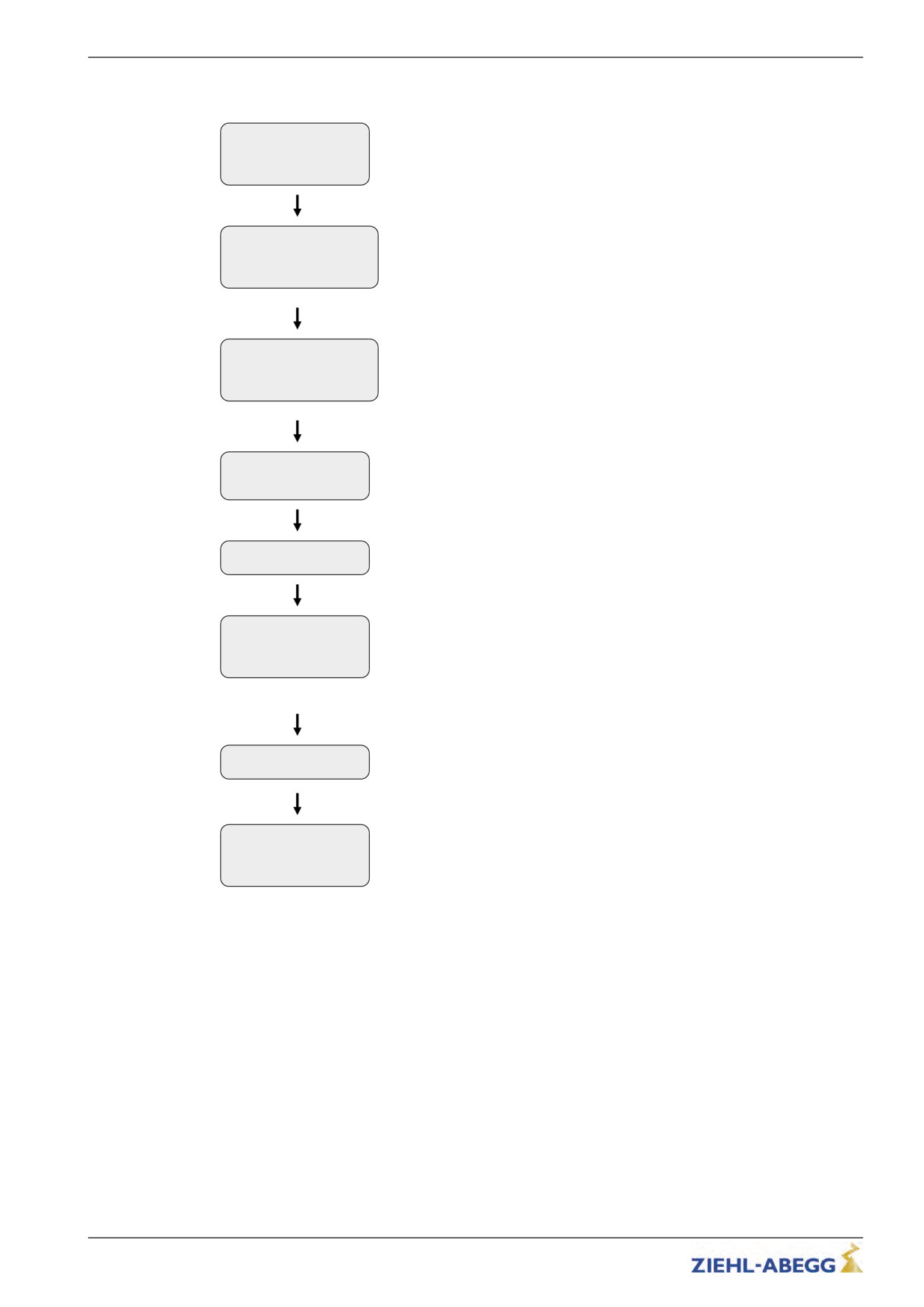
Special functions
Carrying out the load-free alignment with SSI-encoder
MMC Recorder
Select menu Encoder adjustment
->Encoder adjust.
Safety gear
HW-Ident.
Encoder-adjust.
Select parameter "ENC_OFF"
|-" ENC_OFF 0.00
DEG
|-"
0.00
Enter "ENC_OFF=0"
Encoder Offset
Encoder-adjust.
Select parameter "ENC_ADJ"
|-" ENC_ADJ Off
|-"
On
Switch on encoder adjustment with "ENC_ADJ=ON"
Encoder adjustment
CHECK or
Start Encoder-adjustment with [START]
START adjustment?
[Esc][x][CHK][START]
Keep the inspection run push-button pressed.
Press inspection!
[Esc]
Wait.Check encoder
The motor is powered in phase U and the rotor to zero of the next pole.
function.
+514 +512 INC/P
Encoder check, check the motor data for plausibility.
- Display of number of expected (calculated) impulses / pole pair (e.g. 512)
- Display of impulses counted between the poles (e.g. 514)
Wait
+12.9A -6.5A -6.47A
Rotor is held in zero point of the next pole
- Display of motor current of phases U V W
Difference within
one pole +110.70°
Offset value (electrical angle, 360° per pole)
Adjust SSI encoder
diff. to ZERO ...
153/200
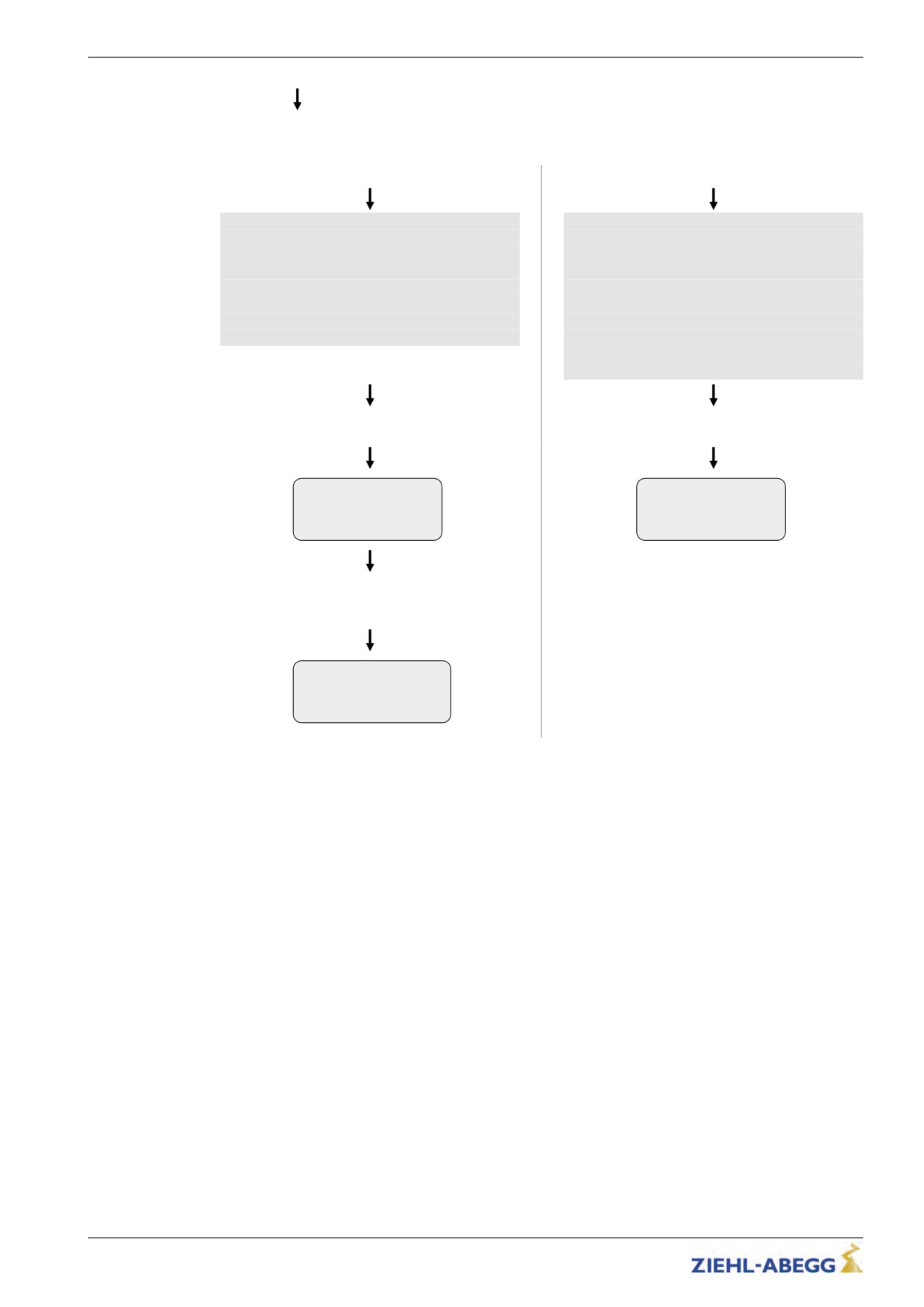
Special functions
Adjust encoder mechani-
cally?
No
Yes
Adjustment by entering the offset value:
Mechanical adjustment of the encoder:
The encoder is not moved mechanically, the off-
Adjust the encoder as exactly as possible to the
set value is retained and is corrected by entering
value 0 ° by turning and tighten the locking screw
the encoder offset value in the controller unit.
carefully, correct the encoder position if neces-
The offset value must be available when chang-
sary.
ing devices!
At the end of the adjustment procedure the en-
If the value is not available, a new encoder ad-
coder must be tightened and value close to 0.
justment must be made!
At deviations less than ± 2.00 ° the adjustment is
considered correct. A
deviation of max. ± 1 ° is recommended.
End the adjustment procedure by switching off
End the adjustment procedure by switching off
the inspection run.
the inspection run.
Please check and
Mechanical SSI
if necessary set
adjustment is quite
ENC_OFF=249.32°
correct!
[OK]
[OK]
The encoder offset must be corrected to the
specified value!
The value must be noted.
Encoder-adjust.
|-" ENC_OFF 249.32
DEG
|-"
249.32
Encoder Offset
154/200
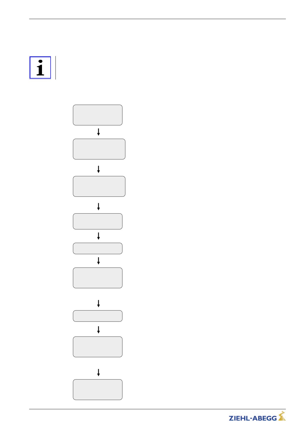
Special functions
15.2.2
Load-free alignment EnDat-Encoder
When aligning the EnDat encoder, the frequency inverter supplies the motor with direct current. During
this, the rotor jumps to the middle of the nearest poles. In this rotor position, the offset value is stored
in the encoder, which sets the encoder to the “0“ position.
Information
The calibration should always be done twice. Any inaccuracy in the 1st calibration is detected by the
2nd calibration and can be corrected.
Carrying out the load-free alignment with EnDat-encoder
MMC Recorder
Select menu Encoder adjustment
->Encoder adjust.
Safety gear
HW-Ident.
Encoder-adjust.
Select parameter "ENC_OFF"
|-" ENC_OFF 0.00
DEG
|-"
0.00
Enter "ENC_OFF=0"
Encoder Offset
Encoder-adjust.
Select parameter "ENC_ADJ"
|-" ENC_ADJ Off
|-"
On
Switch on encoder adjustment with "ENC_ADJ=ON"
Encoder adjustment
CHECK or
START adjustment?
Start Encoder-adjustment with [START]
[Esc][x][CHK][START]
Press inspection!
Keep the inspection run push-button pressed.
[Esc]
Wait.Check encoder
The motor is powered in phase U and the rotor to zero of the next pole.
function.
+514 +512 INC/P
Encoder check, check the motor data for plausibility.
- Display of impulses counted between the poles (e.g. 514)
- Display of number of expected (calculated) impulses / pole pair (e.g. 512)
Wait
Rotor is held in zero point of the next pole
+12.9A -6.5A -6.47A
- Display of motor current of phases U V W
Difference within
Display of difference between calculated and measured angle between 2
one pole -1.89
poles
! Stop Inspection !
End the adjustment procedure by switching off the inspection run.
The offset value is saved in the encoder.
Encoder adjustment
was successfully
finished
[EXIT]
155/200
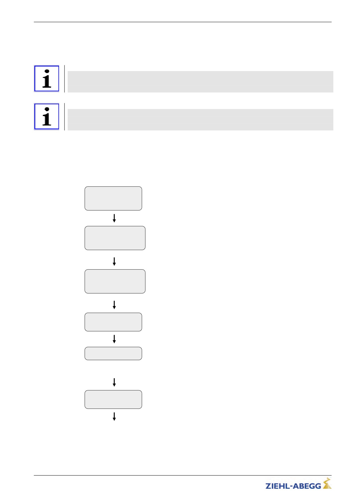
Special functions
15.2.3
Checking the load-free alignment of the SSI- & EnDat-encoders
When checking the encoder offset, the frequency inverter supplies each individual pole in the motor
with direct current. The offset is determined on each pole and the average offset is calculated from
that. This offset can be stored in the frequency inverter.
Information
The offset determined during the inspection is not stored in the frequency inverter because if the
inverter is replaced, the new inverter will not have the identical encoder offset. You must carry out a
new encoder offset alignment or enter the old encoder offset.
Information
During the encoder offset alignment, the driving disk must turn to the right (when looking at
the driving disk). Once the alignment is complete, the driving disk must be located in the same
position as at the start of the process.
Saving the checking
To save the result, a memory card needs to be in the X-MMC card slot during the check.
The result is filed under travel number.POL in the folder/3BF/DEVICE/Seriennummer/LST.
Carrying out the checking of the encoder offset
MMC Recorder
->Encoder adjust.
Select menu Encoder adjustment
Safety gear
HW-Ident.
Encoder-adjust.
Select parameter "ENC_OFF"
|-" ENC_OFF 0.00
DEG
|-"
0.00
Enter "ENC_OFF=0"
Encoder Offset
Encoder-adjust.
|-" ENC_ADJ Off
Select parameter "ENC_ADJ"
|-"
On
Switch on encoder adjustment with "ENC_ADJ=ON"
Encoder adjustment
CHECK or
Start check with [CHK]
START adjustment?
[Esc][x][CHK][START]
Press inspection!
[Esc]
Keep the inspection run push-button pressed for approximately 2 minutes.
The offset value check now runs automatically and lasts about 2 minutes.
The rotor now makes a full revolution and the offset value is determined at
every pole.
Press inspection!
Iu + 13.0A
Iv + 6.5A
156/200
Special functions
WAIT 0/0A 36C
Information is shown in the display during automatic adjustment:
||- - - - - - -80°
ACT >> prog:+15859
Line 1:
POL:2 real:+15859
0/0A: Current in motor phase U / V
36: Current temperature of the power unit
Line 2:
Display rotor position
Line 3:
ACT: Current action
M1 / M2: Measurement 1/2
-> <- Slow positioning of a pole
>> << Fast positioning of the next pole
prog: Latest current pointer position
Line 4:
POLE: Number of the approached pole pair
real: Currect encoder position within a pole
Stop inspection!
Release inspection run push-button
[Esc]
ERR_AVG: -1.42°
Result of the check is displayed:
ERR_MAX: +0.37°
Optimum
Line 1:
ENC_OFF: 1.10° [OK]
ERR_AVG: Average error in degrees (electr. angle)
Line 2:
ERR_MAX: Maximum error in degrees of average value
Line 3+4:
Optimum ENC_OFF: Correction factor encoder offset (electr. angle)
157/200
Special functions
15.2.4
Rotary encoder calibration with closed brake
If the encoder is calibrated with the brake closed, there is no need to take the cables off the traction
sheave. This allows calibration to be performed with much less effort.
Caution!
The electric brake of the motor must not open during the encoder offset alignment!
CAUTION!
It is recommended to remove the electrical connection of the brake for the duration of the
encoder offset alignment!
Information
Considerable noise may occur at the motor for approx. 10-15 s during alignment. These noises
are caused by the special form of energization of the motor and are normal for this kind of
encoder offset alignment.
Pleas keep the button for the inspection travel still closed!
Caution!
CAUTION!
If the device is replaced, the offset needs to be entered in the new device!
Perform calibration of EnDat or SSI encoders
MMC Recorder
->Encoder adjust.
Select menu Encoder adjustment
Safety gear
HW-Ident.
Encoder-adjust.
Select parameter "ENC_OFF"
|-" ENC_OFF 0.00
DEG
|-"
0.00
Enter "ENC_OFF=0"
Encoder Offset
Encoder-adjust.
|-" ENC_ADJ Off
Select parameter "ENC_ADJ"
|-"
On
Switch on encoder adjustment with "ENC_ADJ=ON"
Encoder adjustment
CHECK or
key (beneath [x]).
START adjustment?
[Esc][x][CHK][START]
Is the elec. connec.
to the mechanical
Disconnect electrical connection of the mechanical brake.
brake disconnected?
[Esc] [Yes][No]
key.
Press inspection!
Keep the inspection run push-button pressed for approximately 2 minutes.
[Esc]
*Set test current
Motor voltage is increased until motor current flows.
0 8.8A 23V
Calibration is performed.
158/200
Special functions
Stop inspection !
Release inspection run push-button
*Result: 2.7A
132-222 -> 176/ 356
Result of the adjustment is displayed (176 / 356)
ENC_ABS=263
If ENC_OFF = ? is displayed, it is not possible to determine the correct
ENC_OFF=356 [END]
Encoder Offset. In this case one of the two results (176 or 356 in the
example) is correct. It is recommended to move the motor shaft to a different
position by briefly releasing the brake and to repeat the calibration. If correct
calibration i still not possible, a test run must be made with both of the
received results. With one result the motor runs error-free, with the other
result uncontrolled movements of the motor can occur!
Save new ENC_OFF?
Prompt whether determined Encoder-Offset (ENC_OFF) is to be saved in
[no] [yes]
the Encoder Calibration/ENC_OFF menu
[yes]: Value is saved
[no]: Value is not saved
159/200