ZETADYN 3BF. Operating instruction (Part.-No. 00163264-GB 2/200) - page 2
Electrical installation
5.19.3
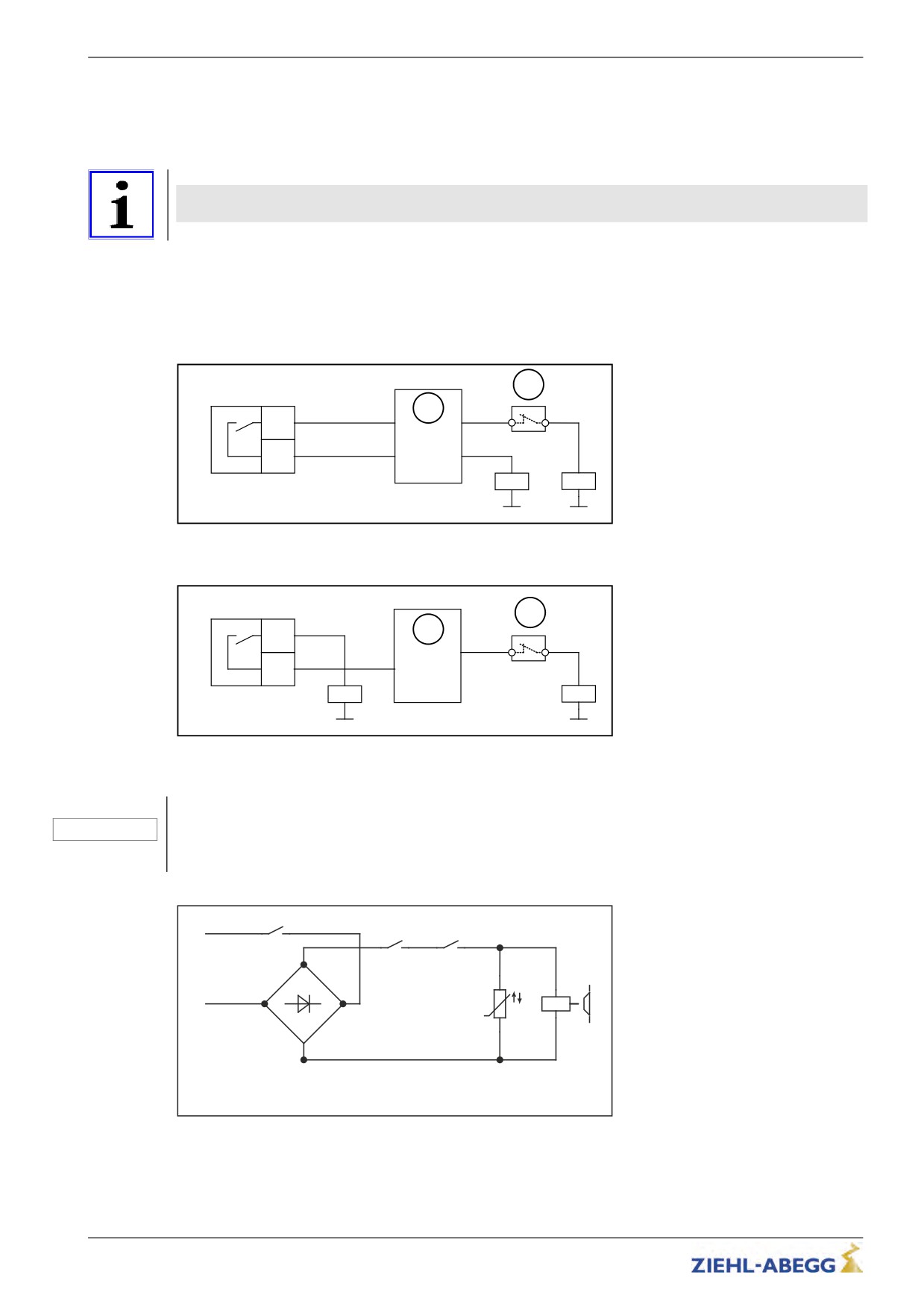
Triggering of the brakes
The signal for controlling the brakes is provided via a zero potential digital output (see "Digital
outputs"). This normally open contact can be used either by the control for further processing or
directly for switching the brake contactor (see fig.).
Information
To achieve optimum travel and position behavior, the brakes must be instantaneously opened and
closed via this contact!
To reduce noises during brake disconnect, during normal operation the brakes should be switched to
the alternating current side (K4). The brakes are switched-off slower and thus quieter through the
rectifier.
To ensure instantaneous brake application in emergencies, during inspection drives and return rides,
use a second contactor (K3), which disconnects the brakes from the direct current side. Integrate this
contactor into the safety circuit.
2
X-OUT
1
Ox4
in
out
Ox1
V+
K4
K3
Activating the brakes by the control system
1
Modulation
2
Safety circuit
X-OUT
2
Ox4
1
out
Ox1
V+
K4
K3
Activating the brakes by the frequency inverter and control system
1
Modulation
2
Safety circuit
Caution!
Brakes, which are connected to the direct current side, must be protected against excess voltage from
CAUTION!
the switching actions by using corresponding varistors!
Due to the high operating current, master contactors must be used to switch the brakes!
K4
1
2
L
K3
K3
1
2
3
4
+
N
~
~
U Y
-
Simplified diagram for brake activation
The contacts from K3 must close before the contact from K4 and are only permitted to open after the
contact from K4 has opened.
40/200
Electrical installation
5.20
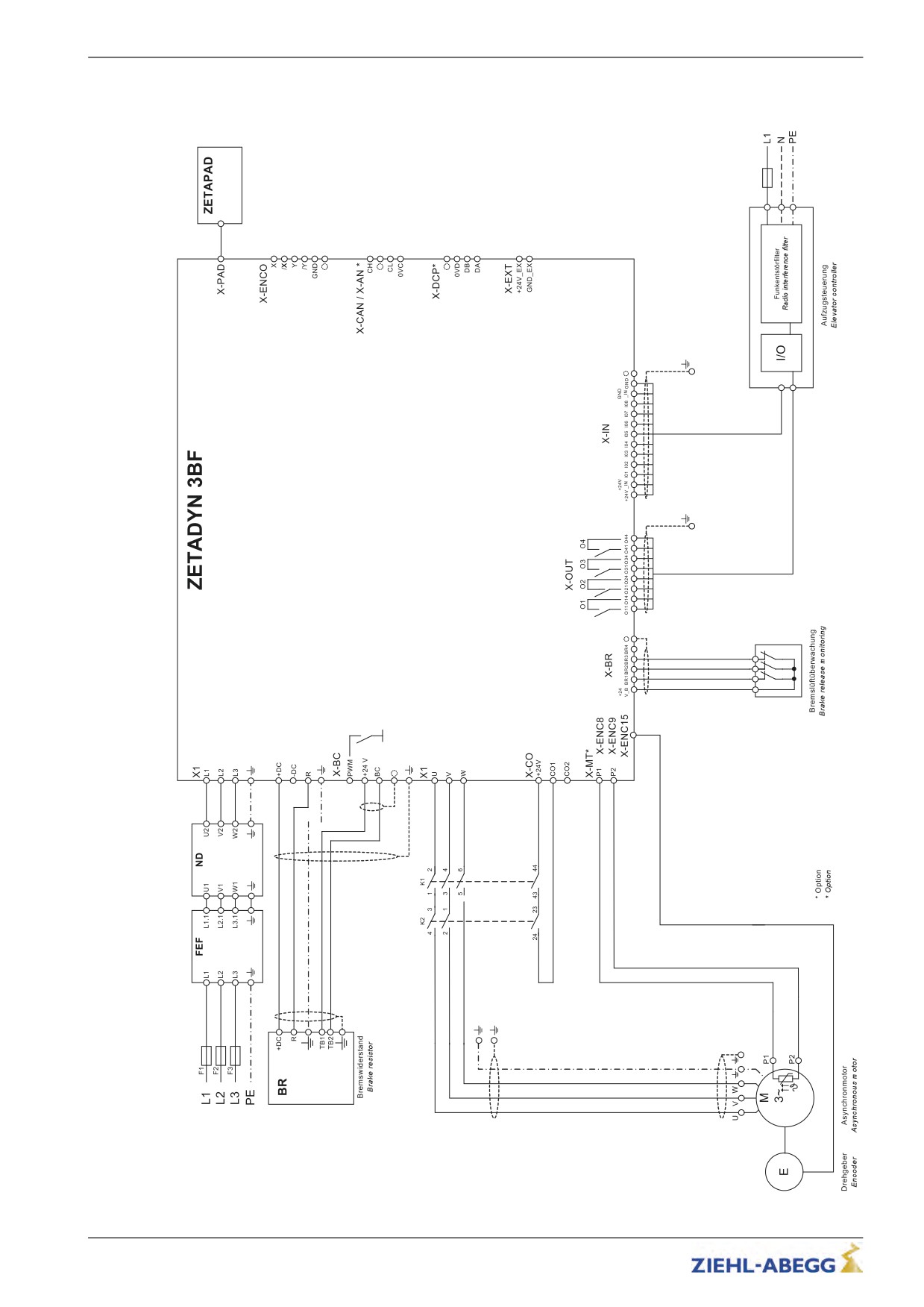
Connection suggestion ZETADYN 3BF (asynchronous motor)
41/200
Electrical installation
5.21
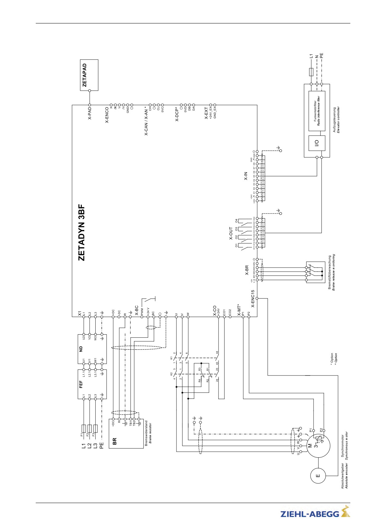
Connection suggestion ZETADYN 3BF (synchronous motor)
42/200
Accessories
6
Accessories
6.1
Line reactor-radio interference filter
6.1.1
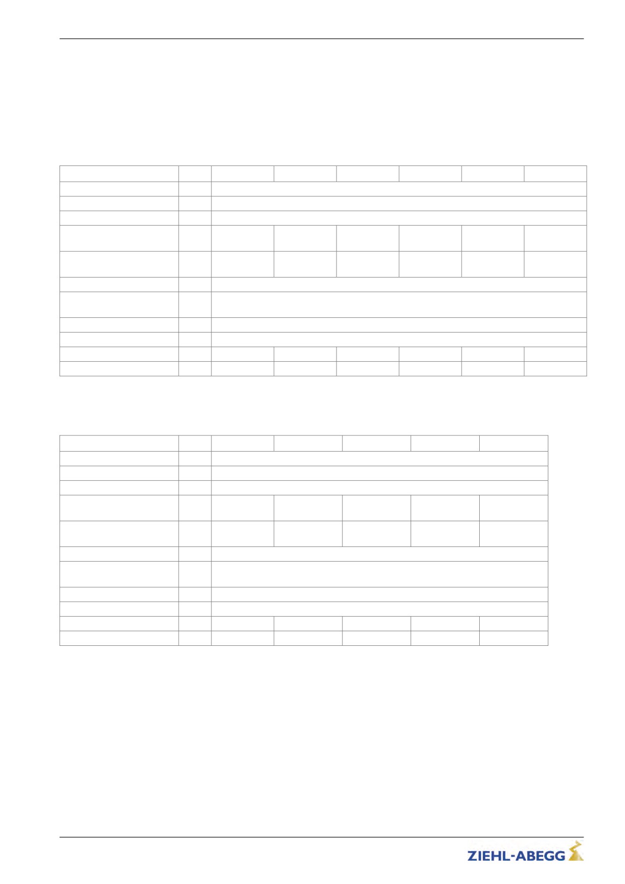
Technical data line reactor and radio interference filter
Line reactor type ND011 - ND040
ND011
ND013
ND017
ND023
ND032
ND040
Electrical data
Mains connection voltage
[V]
3~ 400 ±10 %
Mains frequency
[Hz]
50 / 60
Rated current for 25 % duty
[A]
11
13
17
23
32
40
cycle
Rated current for 30 % duty
[A]
-
-
-
-
-
-
cycle
Ambient conditions
Ambient conditions opera-
[°C]
40
tion
Protection class
IP00
Physical data
Dimensions w x h x d
[mm]
125x135x61
125x135x71
125x135x71
155x160x80
155x170x95
190x200x85
Weight
[kg]
2,0
2,5
2,5
4,0
5,0
6,5
Line reactor type ND050 - ND180
ND050
ND062
ND074
ND110
ND180
Electrical data
Mains connection voltage
[V]
3~ 400 ±10 %
Mains frequency
[Hz]
50 / 60
Rated current for 25 % duty
[A]
-
-
-
-
-
cycle
Rated current for 30 % duty
[A]
50
62
74
110
180
cycle
Ambient conditions
Ambient conditions opera-
[°C]
40
tion
Protection class
IP00
Physical data
Dimensions w x h x d
[mm]
190x200 x68
190x200 x120
190x200 x120
230x280x150
230x350x150
Weight
[kg]
8,0
9,0
10.0
14
21
43/200
Accessories
Radio interference filter FEF011KK4D - FEF050KK4D
FEF011KK4D
FEF023KK4D
FEF040KK4D
FEF050KK4D
Electrical data
Mains connection voltage
[V]
3~ 480 +10 %
Mains frequency
[Hz]
50 / 60
Rated current for 30 % duty
[A]
11
23
40
50
cycle
Ambient conditions
Ambient conditions opera-
[°C]
-25 ... +85
tion
Protection class
IP20
Physical data
Terminal cross-section
[mm²]
4.0
10.0
16.0
Dimensions w x h x d
[mm]
40x190x70
45x250x70
50x270x85
85x258x90
Weight
[kg]
0,7
1,0
1,4
1,5
Radio interference filter FEF074KK4D - FEF180KK4D
FEF074KK4D
FEF180KK4D
Electrical data
Mains connection voltage
[V]
3~ 480 +10 %
Mains frequency
[Hz]
50 / 60
Rated current for 30 % duty
[A]
74
180
cycle
Ambient conditions
Ambient conditions opera-
[°C]
-25 ... +85
tion
Protection class
IP20
Physical data
Terminal cross-section
[mm²]
16.0
95.0
Dimensions w x h x d
[mm]
85x258x90
130x450x180
Weight
[kg]
2,0
6,0
6.1.2
Mechanical installation
Information
The following points must be complied with during the mechanical installation to avoid causing a defect
in the device due to assembly errors or environmental influences:
Before installation
• Remove the device from the packing and check for any possible shipping damage
• Carry out installation only on a clean, level and stable foundation
• Assemble the device outside of the traffic area
During installation
• Mount the device in a torsion free conditions
• Mount the device in a torsion free conditions
• avoid that drilling chips, screws and other foreign bodies reach the interior of the device
Ambient conditions
• mounting the device on vibrating components is not allowed
• the device must not be exposed to any shock
• Prevent humidity
44/200
Accessories
• Avoid aggressive and conductive materials in the environment
6.1.3
Dimensions
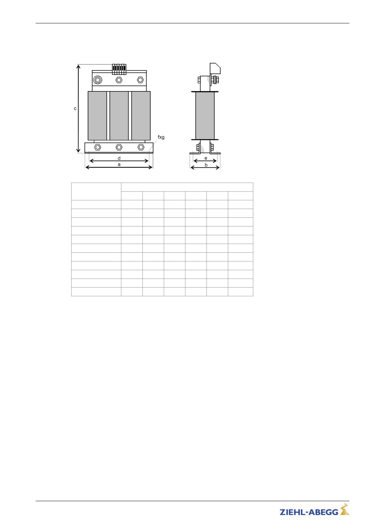
Dimensions power choke ND
Dimensions [mm]
a
b
c
d
e
fxg
ND011
125
61
135
100
45
5x8
ND013
125
71
135
100
55
5x8
ND017
125
71
135
100
55
5x8
ND023
155
80
160
130
57
8x12
ND032
155
95
170
130
72
8x12
ND040
190
85
200
170
58
8x12
ND050
190
120
200
170
68
8x12
ND062
190
120
200
170
78
8x12
ND074
190
120
200
170
78
8x12
ND110
230
150
280
180
120
8x12
ND180
230
150
305
180
122
9x12
45/200
Accessories
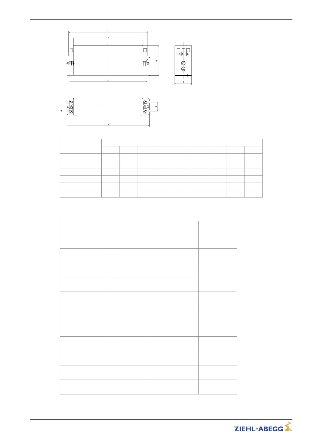
Dimensions radio interference filter FEF
Dimensions [mm]
A
B
C
D
E
F
G
H
L
FEF011KK4D
190
40
70
20
180
160
5,4
M5
185
FEF023KK4D
250
45
70
25
235
220
5,4
M5
245
FEF040KK4D
270
50
85
30
255
240
5,4
M5
265
FEF050KK4D
250
85
90
60
235
220
5,4
M6
258
FEF074KK4D
250
85
90
60
235
220
5,4
M6
258
FEF180KK4D
380
130
180
102
365
350
6.5
M10
450
6.1.4
Allocation of the line reactor-radio interference filter to the frequency inverter
Radio interference fil-
Inverter
Line reactor
Part no.
ter
ND011
-
357180
ZETADYN 3BF011
-
FEF011KK4D
357192
ND013
-
357181
ZETADYN 3BF013
-
FEF023KK4D
357176
ND017
-
357182
ZETADYN 3BF017
-
FEF023KK4D
357176
ND023
357183
ZETADYN 3BF023
-
FEF023KK4D
357176
ND032
357184
ZETADYN 3BF032
FEF040KK4D
357177
ND040
357185
ZETADYN 3BF040
FEF040KK4D
357177
ND050
-
357186
ZETADYN 3BF050
-
FEF050KK4D
357178
ND062
-
357187
ZETADYN 3BF062
-
FEF074KK4D
357179
ND074
-
357188
ZETADYN 3BF074
-
FEF074KK4D
357179
ND110
-
357196
ZETADYN 3BF110
-
FEF180KK4D
357199
ND180
-
357197
ZETADYN 3BF180
-
FEF180KK4D
357199
46/200
Accessories
6.2
Operating terminal ZETAPAD
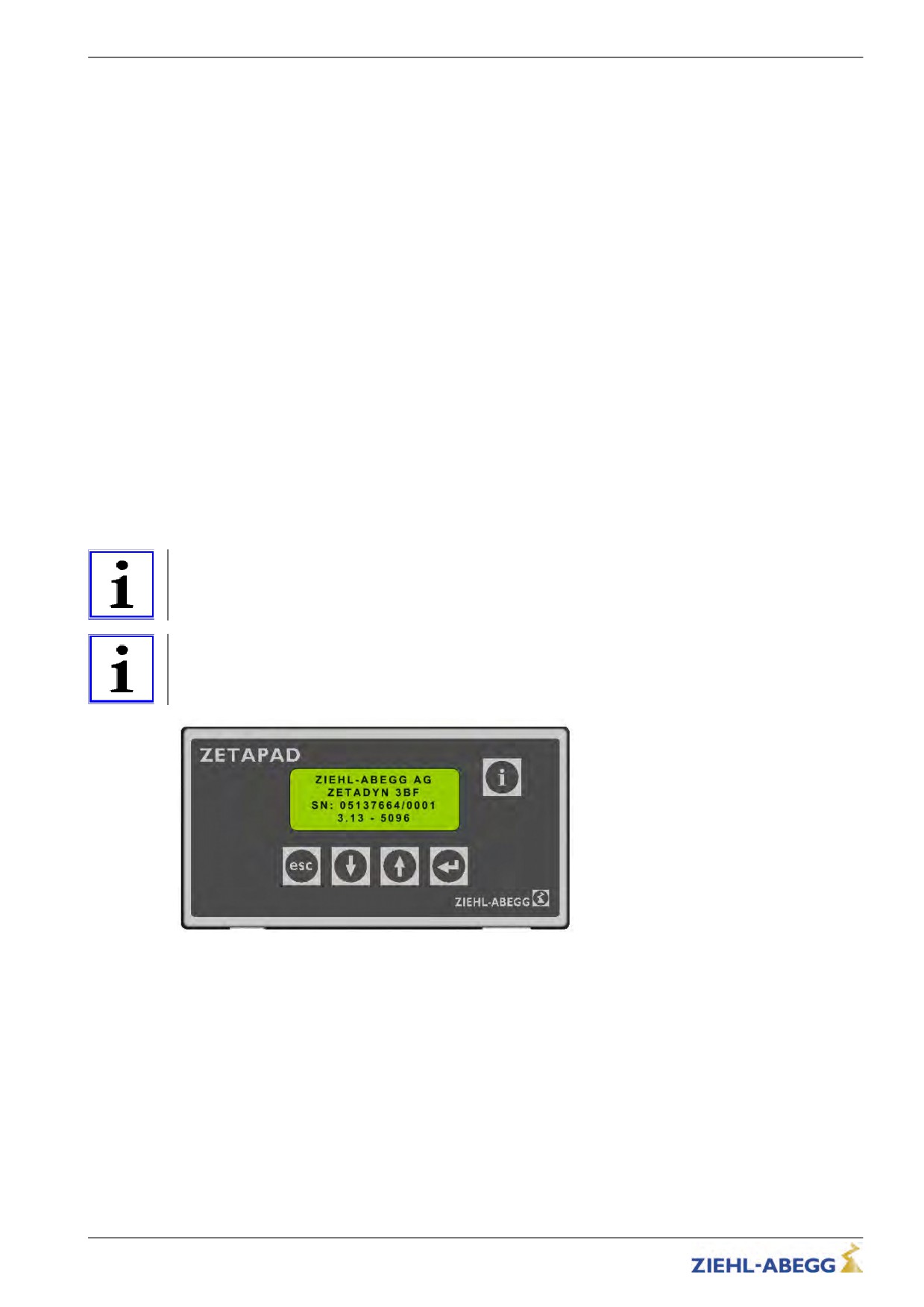
The ZETAPAD is an operating module that is independent of the frequency inverter. It can be used to
operate and configure all ZETADYN 3 type frequency inverters.
When using longer connection lines, remote control of the frequency inverter is feasible.
6.2.1
Mounting / Fastening
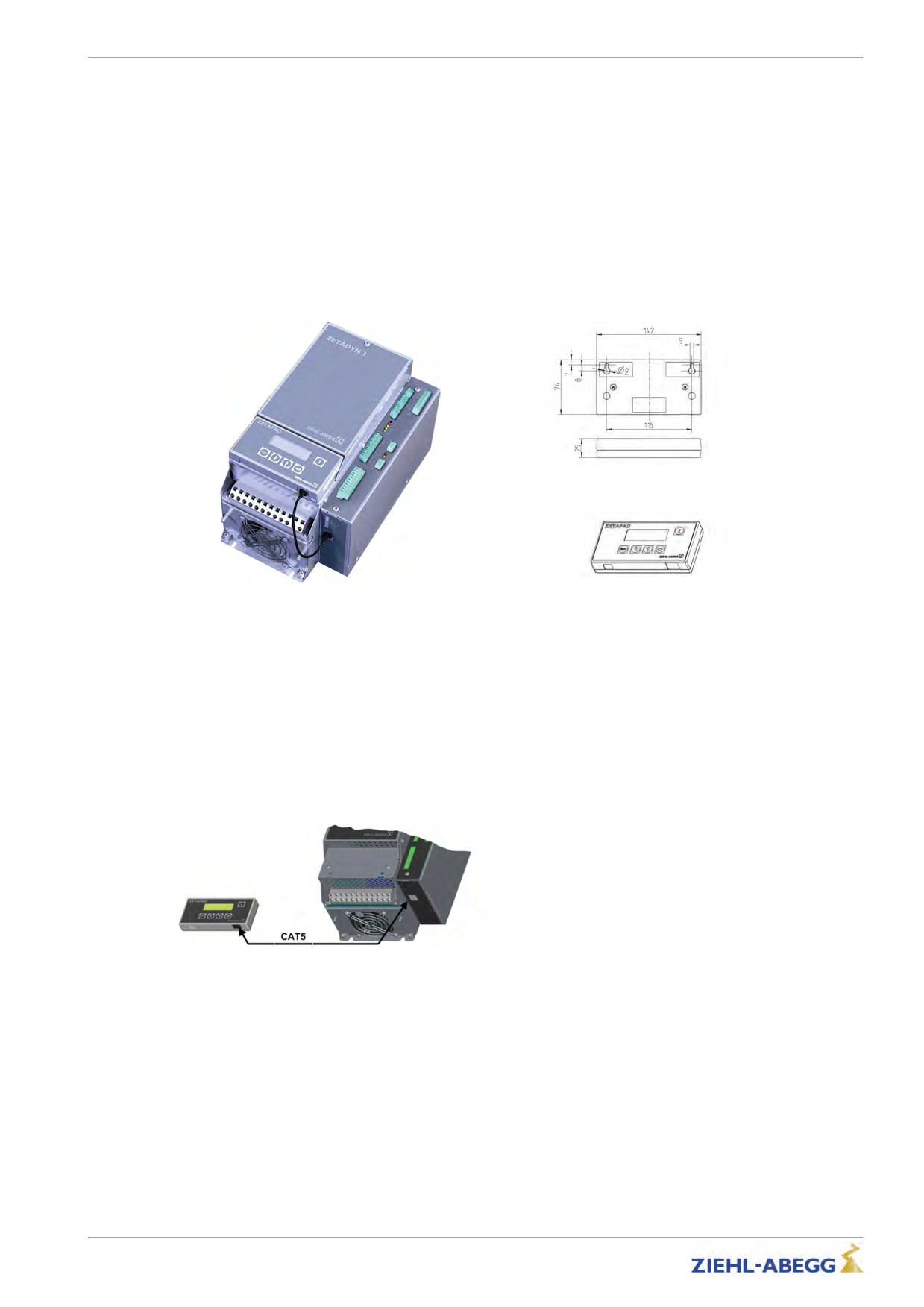
The fastening takes place with the provided magnetic stripes, which will be affixed to the back-side,
on the front-side of the frequency inverter and all magnetisable surfaces.
Two keyhole notches are available on the rear for mounting the ZETAPAD to non-magnetic surfaces
(see Fig.).
6.2.2
Dimensions
ZETAPAD dimensions
Mounting ZETAPAD to ZETADYN 3
6.2.3
Connection
The connection has to be effected on the RJ45-female plug of the operating terminal and the
ZETADYN 3 (X-PAD).
Connection cable
CAT5 network cable, 8-core
both sides RJ-45 plug, 8-pole
maximum line length: 50 m
line cross-section >= AWG26
ZETAPAD connection
47/200
Operation and parameterising
7
Operation and parameterising
7.1
Possibilities for operation and configuration
The following can be performed with the aid of the various operating facilities:
• The parameters needed for commissioning can be set
• Simple measurement and control functions can be carried out
• Service conditions can be recorded
7.1.1
Operating terminal ZETAPAD
The ZETAPAD is an operating module independent of the frequency inverter. It can be used to operate
and configure frequency inverters of the ZETADYN 3 type and evacuation modules of the EVAC 3
type.
7.1.2
Remote control via ZETAMON software
When the ZETAMON software is used the frequency converter can be operated by a PC / Notebook
(see chapter "ZETAMON Software").
7.1.3
Remote control via the elevator controller display
Prerequisite is an elevator control system which supports the DCP protocol or CANopen lift protocol
as well as an existing connection between frequency converter and elevator control system. Please
see the elevator control system operating manual for information on operating the converter via the
elevator control system.
7.2
Menu navigation
Information
The menu navigation for the ZETAPAD and ZETAMON operating facilities is uniform! Please inform
yourself about navigation with an elevator control by using the corresponding operating instructions!
Information
Modifying parameters is only possible when the machine is in standstill!
Operating interface ZETAPAD and ZETAMON
48/200
Operation and parameterising
7.2.1
Control key functions
• back to menu selection
• Back to parameter selection
• Negation of yes-no queries
• Cancel
• Confirming menu selection
• Confirming parameter values
• Confirming parameter values
• Affirmation of yes-no queries
• Menu selection
• Parameter selection
• Increasing parameter values
• Menu selection
• Parameter selection
• Reducing parameter values
• Show / exit INFO menu
• Display of current operational states
7.2.2
Menu and parameter navigation
ZIEHL-ABEGG SE
Main page
ZETADYN 3CS011-D
- Actuate with any key
SN: 09229587/0002
Phone: +49 794016308
ZETADYN 3
Menu section
- Select required menu
->Startup
Statistic
Confirm menu selection
Memory Card
Startup
Parameter section
USR_LEV Basic
Parameter selection
->MOT_TYP SM250
- Confirming parameter values
n 96 rpm
Startup
Changing parame-
- Enter / select parameter value.
|-" MOT_TYP SM225
ter
|-"
SM250
- Confirm value
Motortype
7.2.3
The different operating levels
The firmware of the ZETADYN 3 is divided into two operating levels:
Basic-Level
• Three menus are available here: Startup, Statistics and Memory Card
• Starting up takes place exclusively in the "Startup" menu.
Advanced-Level
• In the Advanced-Level all parameters as described in chapter 10 "Parameter List" are displayed.
• Depending on the parameterisation, unneeded parameters are hidden automatically to give a better
overview.
Information
key.
• The level which is active after the controller start can be set by the parameter LCD &
Password/USR_LEV.
49/200
Operation and parameterising
7.2.4
Meaning of the arrows appearing in the display:
Motor-Typenschild
à Encoder & BC
Selecting a menus in the menu level
Anlage-daten
Steuerung
Motor-Typenschild
n
128
rpm
Selecting changeable parameters in the menu
à f
18.0
Hz
I
40.4
A
Anlage-Daten
Selected parameter can be modified, but is blocked at the mo-
MOD_n* Mit D..i2
ment. The block can be implemented by assigning a password
n*
94
rpm
__D
0.240
m
or functionally (dependent on another parameter)
Start
T_2
1.0
s
Value / function of a parameters is only displayed for informa-
T2_real
0.8
s
tional purposes and cannot be modified.
T_3
0.1
s
Serial-No---------01
i
ZETADYN
3BF013-A
Current position (page number) in the INFO-menue
SN:06128238/0001
3.17-1037
Zahl
MMC-Recorder
□
REC_MOD
On
The recorder for recording measurements on the memory card
REC_CFG
0
is activ
REC_NUM
0
Start
ERR
T_2
1.0
s
Failure of the frequency inverter
ERR
T2_real
0.8
s
The device must be switched off
T_3
0.1
s
7.3
Entering numerical values
Entering numerical parameter values can be done using two different facilities:
7.3.1
Continuous change of a parameter value
After selecting the parameter, the parameter value can be set by continuously changing the numerical
key.
Short keypress: Number is incremented/decremented by 1
Long push on the key: Number automatically increases/decreases until the key is released.
Encoder & BC
|-" ENC_INC 1024
I
|-"
2036
Encoder resolution
7.3.2
Changing individual digits
When changing a parameter by a large value, it is possible to change the individual digits separately
&
key
The selected digit is marked with an arrow.
Encoder & BC
|-" ENC_INC 1024
I
|-"
2036
W
50/200

Start-up
8
Start-up
Danger!
Defective connections can cause the motor to start unexpectedly or lead to uncontrolled motor
movements.
Reversed connections cause the motor to rotate in the wrong direction. That can cause serious
machine damage.
Caution!
Incorrectly wired connections can destroy the electrical / electronic components.
CAUTION!
Electrostatic discharges can be hazardous to the electronic components and lead to errors in the
software.
You must comply with the following points to prevent machine damage or life-threatening injuries
when commissioning the machine:
• Only suitably qualified personnel are to be entrusted with the commissioning of the device. They
must comply with the safety instructions.
• Before starting work, make sure all tools and external parts have been removed from the machine.
• Activate all safeguards and the emergency-off switches before commissioning.
• Make sure no unauthorized persons are in the machine working area and that no other persons can
be endangered when the installation is started up.
• inspect the electrical connections before the first start
• Pay special attention to the protective measures (e.g. grounding, ...) for the electrostatically
endangered components.
• Also read the chapter "General Safety Instructions".
Information
This commissioning assumes the factory settings for the digital inputs and outputs, encoder inputs and
monitoring contacts have not been modified!
Requirements for error-free commissioning:
• Mains line is connected
• Motor is connected
• Brake chopper or Brake resistor are connected
• Controller and monitoring inputs are connected
• Encoder is connected
Information
Startup takes place in the basic level. To go to the advanced level, press the key long (see chapter
"Opeation and Parameterisation / The different operating levels") or go to the Startup menu and set
the USR_LEV = Advancedparameter.
Start-up
|-" USR_LEV Advanced
|-"
Advanced
User level
8.1
Preconfigured inverter
Inverters preprogrammed by ZIEHL-ABEGG are provided with the following information plate on the
faceplate
Information
Preset parameters
Preset paramters
In these units, the parameters are factory preset, based on customer specific information. Entering
parameters is no longer necessary but the parameters must be checked before commissioning!
51/200
Start-up
8.2
Switching on the frequency inverter
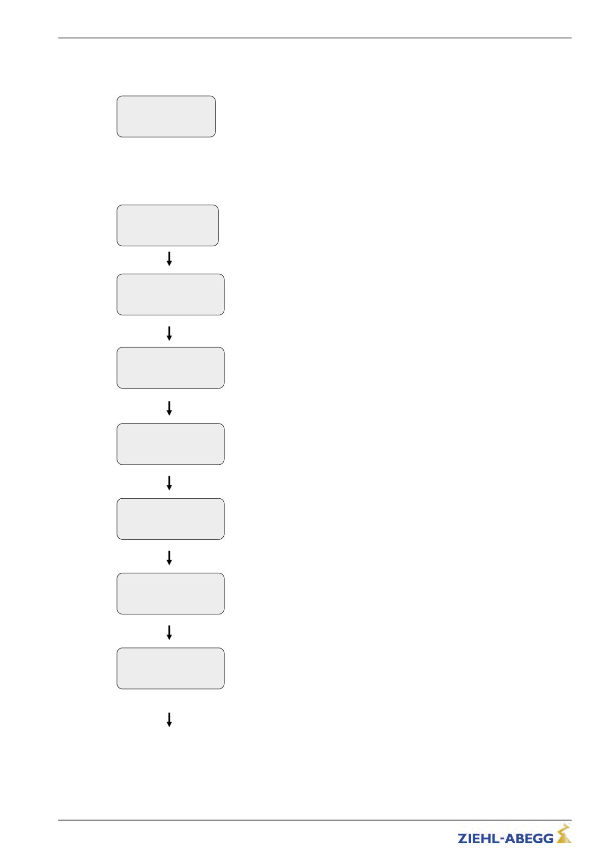
When the mains voltage is applied, the frequency inverter switches on after a self test. The display
shows thefoll owing:
ZIEHL-ABEGG SE
SN:12345678/123
Phone +49 794016308
8.3
Parameterization of the frequency inverter
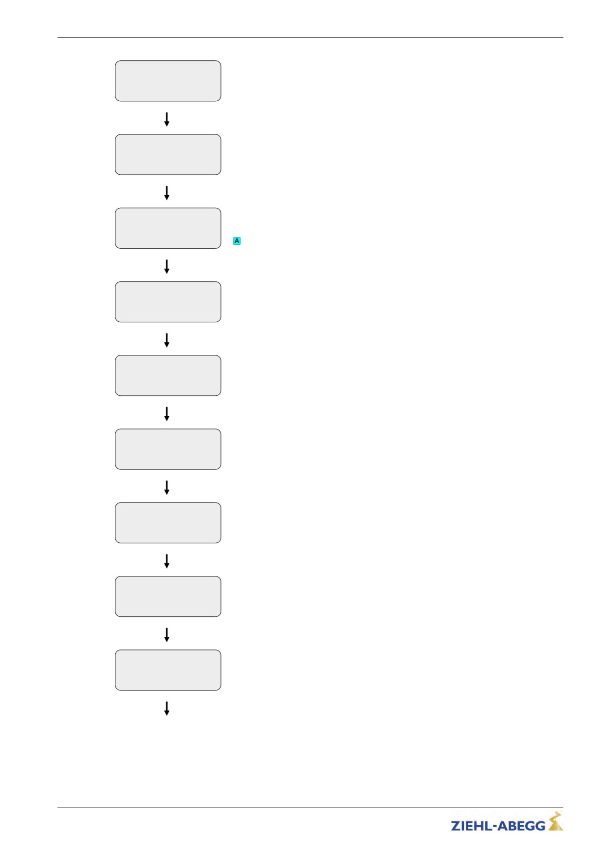
If the frequency inverter doesn't have preset parameters, you have to adjust the following parameters
before start-up.
->Start-up
Statistics
Select menu "Startup"
Memory Card
Start-up
Select parameter "LCD"
|-" LCD
Deutsch
Choose language
|-"
English
The languages German and English are integrated as standard. A third language
Sprache
- Language
can be loaded with the memory card.
Start-up
|-" USR_LEV Basic
Select parameter "USR_LEV"
|-"
Advanced
The level which is active after the controller start can be set by the parameter
User level
USR_LEV.
Start-up
|-" MOT_TYP SM
200
Select parameter "MOT_TYP"
|-"
SM 200
Enter the operated motor type
Motor
Start-up
|-" n
72
rpm
Select parameter "n"
|-"
72
Enter nominal speed of the motor
Rated speed
Start-up
|-" f
18.0
rpm
Select parameter "f"
|-"
18.0
Enter nominal frequency of the motor
Rated frequency
Start-up
|-" f
13.7
rpm
Select parameter "I"
|-"
13.7
Enter nominal current of the motor
Rated current
52/200
Start-up
Start-up
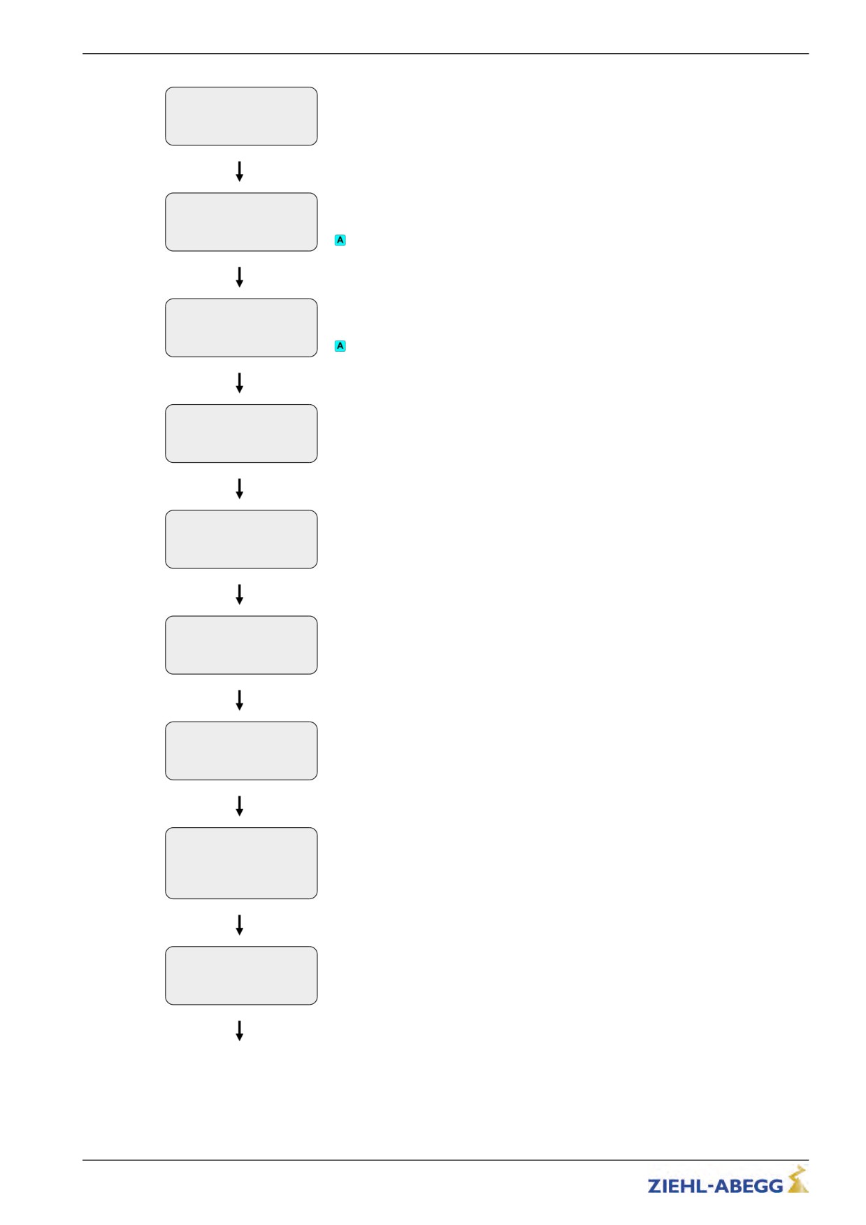
|-" U
360
V
Select parameter "U"
|-"
360
Enter nominal voltage of the motor
Rated voltage
Start-up
|-" f
5.5
rpm
Select parameter "P"
|-"
5.5
Enter nominal power of the motor
Rated power
Start-up
Select parameter "cos phi"
|-" cos phi 0.75
|-"
0.75
Enter power factor of the motor
Power factor
Possible only for asynchronous motors
Start-up
|-" TYPE
Star
Select parameter "TYP"
|-"
Triangle
Choose connection type of the motor
Connection type
Start-up
|-" ENC_TYP EnDat/SSI
Select parameter "ENC_TYP"
|-"
EnDat/SSI
Enter the type of encoder used
Encoder type
Start-up
|-" ENC_INC 2048
INC
Select parameter "ENC_INC"
|-"
2048
Enter the encoder resolution
Encoder resolution
Start-up
|-" BC_TYP BR11
Select parameter "BC_TYP"
|-"
BR11
Enter the used brake resistor or brake chopper
BR/BC type
Start-up
|-" V*
1.00
m/s
Select parameter "V*"
|-"
1.00
Enter the installation rated speed
Nominal speed
Start-up
|-" __D
0.315
m
Select parameter "__D"
|-"
0.400
Enter the diameter of the traction sheave
Driving disk diam.
53/200
Start-up
Start-up
|-" __is
1:1
Select parameter "__is"
|-"
1:1
Enter the installation's type of suspension
Suspension
Start-up
Select parameter "__i1"
|-" __i1
23.00
|-"
23.00
Input of i1 of the gearbox ratio i1:i2
Gearbox i1:i2
Possible only for asynchronous motors
Start-up
Select parameter "__i2"
|-" __i2
1
|-"
1
Input of i2 of the gearbox ratio i1:i2
Gearbox i1:i2
Possible only for asynchronous motors
Start-up
|-" Q
600
kg
Select parameter "Q"
|-"
600
Enter the elevator installation's rated load
Nominal load
Start-up
|-" F
1000
kg
Select parameter "F"
|-"
1000
Enter the car weight
Elevator car weight
Start-up
|-" G
1300
kg
Select parameter "G"
|-"
1300
Enter the counterweight
Counterbalance
Start-up
|-" CONFIG
01: ZA_IO
Select parameter "CONFIG"
|-"
01: ZA_IO
Configuration of the digital inputs according to the used control system and type of
Configuration
communication
Start-up
|-" MO_DR
Left
Select parameter "MO_DR"
|-"
Left
Changing the rotating direction of the motor
Motor rotation direc-
It must be observed the with triggering the input RV1 the cabin drives upwards
tion
Start-up
Select parameter "CO"
|-" CO
C01
|-"
C01
Definition of the contactor monitoring
Contactor monitoring
The contactor monitoring has to be connected to the inverter obligatory!
54/200
Start-up
Start-up
|-" BR
Off
Select parameter "BR"
|-"
3*NO
Definition of the brake monitoring
Brake monitor
Start-up
|-" P1P2
Off
Select parameter "P1P2"
|-"
PTC
Motor temperature monitoring
Motor temp. monitor
Start-up
Select parameter "K_START"
|-" K_START 1.0
Start gain
|-"
1.0
Multiplicative factor for the parameter "Controller/SPD_KP"
Control vers. at start
Increasing the PI controller during the start-up
Start-up
|-" SPD_KP
1.00
Select parameter "SPD_KP"
|-"
1.00
Multiplication factor to modify the calculated basic amplification SPD_C
Controller basic gain
8.4
Automatic operating-curves default
Using the automatic operating-curve defaults, the parameters responsible for operating curves and
travel speeds are pre-assigned dependent on the "installation nominal velocity "V*".
After changing the parameter V*, you can confirm the request " automatic pre-signment?" with yes or
no.
Preconfigured parameters through the automatic operating defaults:
"Acceleration" menu
"Deceleration" menu
"Travelling" menu
A_POS
A_NEG
V_2
R_POS1
R_NEG1
V_3
R_POS2
R_NEG2
55/200
Start-up
8.5
Setting the switch-off points
8.5.1
Cut-off points for travel speed V_3
The deceleration paths V_3 to V_1 or V_3 to standstill (with DCP2 and DCP4 protocols) can be read
out directly on the frequency inverter in the info menu/page 03.
Dist.
----------
03
sa: 0.00 s21: 0.52m
sr:^0.00 s31: 1.45m
s1: 0 sd: 0.52m
s31: Display of calculated deceleration path V_3 R V_1 or V_3 R Standstill
The following parameters influence the deceleration paths:
• V_1 (Positioning speed)
• V_3 (Traveling speed)
• R_NEG1 (upper round-off)
• R_NEG2 (lower round-off)
• A_NEG (Deceleration)
When a parameter is changed, the newly calculated deceleration path is (s31) indicated in the display
after confirming the modification.
Travel
s31= 1.53m [ok]
s31: Display of calculated deceleration V_3 R V_1 or V_3 R Standstill after modifying V_3
To have some leeway to optimize the travel behavior, the interrupt point is set to a deceleration path
larger than that, which was calculated.
The crawl path can be shortened later directly on the inverter in the Decelerating/S_DI3 menu
To reach almost identical positioning in all floors, the interrupt points must be set with a precision of
± 1 cm.
8.5.2
Cut-off points for travel speed V_2
The deceleration paths V_2 to V_1 or V_2 to standstill (with DCP2 and DCP4 protocols) can be read
out directly on the frequency inverter in the info menu/page 03.
Dist.
----------
03
sa: 0.00 s21: 0.52m
sr:^0.00 s31: 1.45m
s1: 0 sd: 0.52m
s31: Display of calculated deceleration path V_2 R V_1 or V_3 R Standstill
The following parameters influence the deceleration paths:
• V_1 (Positioning speed)
• V_2 (Intermediate speed)
• R_NEG1 (upper round-off)
• R_NEG2 (lower round-off)
• A_NEG (Deceleration)
When a parameter is changed, the newly calculated deceleration path is (s21) indicated in the display
after confirming the modification.
Travel
s21= 0.86m [ok]
s21: Display of calculated deceleration V_2 R V_1 or V_2 R Standstill after modifying V_2
If the floor separation is smaller than the calculated deceleration path, the speed for V_2 must be
decreased until the deceleration path is smaller than the floor separation.
56/200
Start-up
8.5.3
Cut-off points for travel speed V_1
To1prevent overshooting the flush alignment, the interrupt points V_1, dependent on the deceleration
A_NEG, must be set between 2 and 5 cm before flush alignment. If the ride ends before alignment,
the interrupt points need to be correspondingly adjusted. To reach almost identical positioning in all
floors, the interrupt points must be set with a precision of ± 1 mm.
8.6
Carrying out the first test run
Warning!
Operating synchronous motors without encoder offset can cause uncontrolled motor movements
An encoder offset adjustment must be made in synchronous motors before starting the first time (see
chapter "Special Functions")!
The offset calibration has already been performed in the factory for ZIEHL-ABEGG motors.
If third-party motors are used, the offset must be performed as follows (obtain information from
manufacturer): Connect motor winding to DC voltage: U R + and V and W R -. Offset value = 0
The first trip must be carried out with the return control or as an inspection trip.
If this trip can be carried out without any problems and without any fault messages, a normal trip can
be made as the next step.
If fault messages appear, an error list is available in the “Diagnose” chapter together with the
corresponding error causes
8.7
Optimisation of the startup and drive behaviour
The "SPD_KP" (amplification) parameter can be used to optimise the setting of the speed controller
acting during travel. The parameter can be changed in the Control/SPD_KP menu.
Control
|-" SPD_KP
1.00
|-"
0.95
Speed controller basic
gain
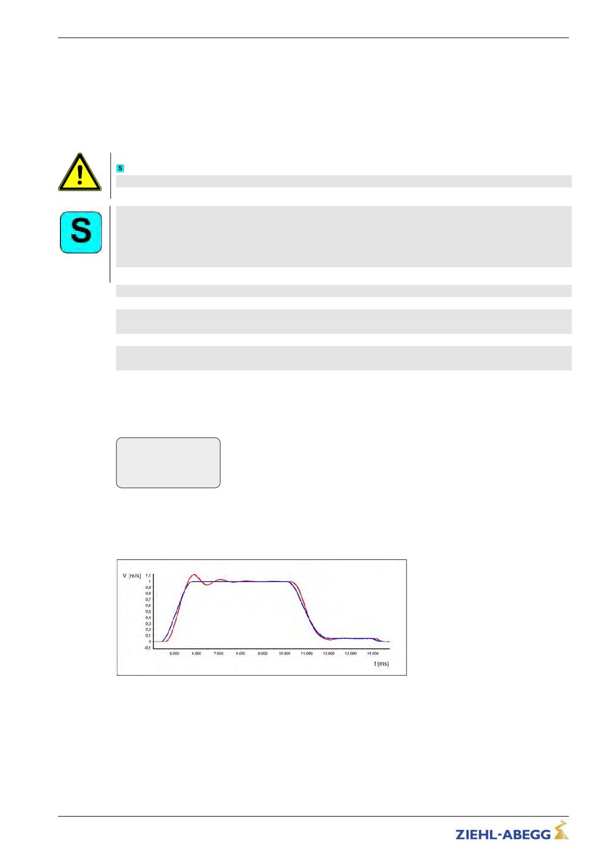
You can generally set the speed control by changing the factor for the basic amplification ("SPD_KP").
If significant control deviations occur during the trip (especially during acceleration and deceleration),
(see Fig.), the amplification has been set too low. In this case, increase the factor for amplification
("SPD_KP").
´
Control deviations when the amplification is set too low
blue Set-value - travel speed
red Actual-value - travel speed
57/200
Start-up
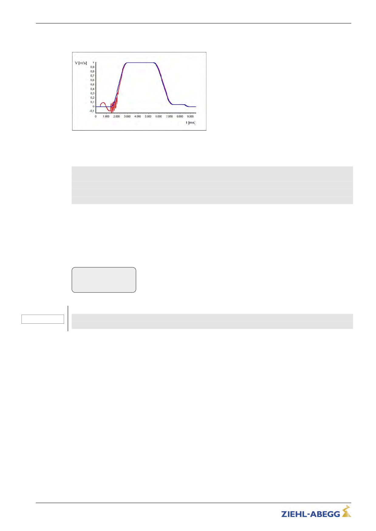
If the motor is noisy or starts vibrating (see figure), amplification is set too high. In this instance, the
factor for amplification ("SPD_KP") should be reduced.
Control deviations when the amplification is set too high
blue Set-value - travel speed
red Actual-value - travel speed
Optimum setting of the speed controller
The following procedure is recommended to obtain an optimum setting of the speed controller:
Increase the parameter Loop control/SPD_KPuntil the motor causes noises/vibrations when starting
up.
Decrease the parameter Loop control/SPD_KPuntil the motor causes no noises/vibrations when
starting up.
Turning away when starting up
Turningawaywhen starting up is indicated by uncontrolled movement of the traction sheave. The
reason for this is too weak a gain of the speed controller for the time at which the brake opens.
If the motor turns away when starting up despite optimum setting of the basic gain (parameter
Controllerl/SPD_KP) this can be optimised by increasing the parameter Start/K_START.
Start-up
|-" K_START 1.0
|-"
3.0
Start gain
Caution!
Before the parameter Start-up/K_START is increased, it must be ensured that the basic gain (
CAUTION!
Control/SPD_KP) is optimally configured!
58/200
Serial communication
9
Serial communication
9.1
DCP (Drive Control & Position)
Information
To operate the installation with DCP protocol, the frequency inverter must be equipped with the
optional board EM3-ENC-CAN-DCP (Art. No. 357107)!
The DCP-mode enables serial activation of the frequency inverter through an RS485 interface.
Through the bi-directional, serial triggering, the control signals are conducted through a 2- or 3-core
connection line. Generally, the lines X-IN andX-OUT are no longer required, which means the wiring
expenditure is reduced to a minimum.
9.1.1
Electrical connection
The connection is made via the interface X-DCP on the frequency inverter (see chapter "Electrical
Installation / DCP Interface (X-DCP)".
9.1.2
The various DCP protocols
DCP_01
The operating principle is similar to a conventional triggering via the (X-IN) control inputs and (X-OUT)
control outputs. The elevator control transmits the required activation signals (e.g. controller enable,
direction of travel, speed, deceleration point) to the frequency inverter as command bits and receives
the status messages as status bits as return information from the frequency inverter (e.g. signals for
mechanical brakes and motor contactor, speed monitoring and general alarm).
DCP_03
The DCP_03 protocol is an expanded version of the DCP_01 protocol. As compared with the DCP_01
protocol, it has:
• faster data transmission
• a faster communication channel
• an automatic compatibility check between the software in the frequency inverter and software in the
control
DCP_02
The transmission of the command and status bit correspond to the DCP_01-protocol. In addition,
travel is residual path oriented: With the start command, the open loop control determines the path to
the next floor for the frequency inverter. This path is continuously updated during the drive (residual
path). The frequency inverter adapts its traveling speed to the residual path and the car arrives directly
at the floor, time optimized and jolt-free without crawl drive. An absolute rotary encoder is required for
setting the residual path!The brake path (shown in the inverter’s display) must be manually entered
into the open loop control beforehand.Through the entered brake path and the current residual path
during an incoming call during the trip, the open loop control can decide whether it is still possible to
stop.If no call comes in latest
DCP_04
The DCP_03 protocol is an expanded version of the DCP_01 protocol. As compared with the DCP_01
protocol, it has:
• faster data transmission
• a faster communication channel
• an automatic compatibility check between the software in the frequency inverter and software in the
control
• a Braking distance transmission: The control unit continuously transmits the braking distance for
the current speed to the open loop control. That means during an incoming call, the trip the open
loop control can decide whether it is still possible to stop.
59/200
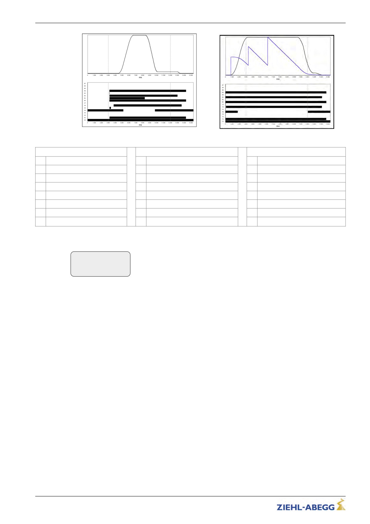
Serial communication
Signal curve DCP_01, DCP_03
Signal curve DCP_02, DCP_04
Command byte
Speed default byte
Status byte
B0
Controller enable RF
G0
slow speed (V1)
S0
inverter ready for the next trip
B1
travel command (start)
G1
readjustment (Vz)
S1
travel active (RB)
B2
stop switch (switching off V_1)
G2
Speed 0
S2
advance warning active
B3
Travel speed V_3
G3
return (V5)
S3
general alarm active (ST)
B4
direction of travel (RV1 or RV2)
G4
Inspection (V4)
S4
speed monitoring (interface/ V_G1)
B5
speed change
G5
Additional speed (V6)
S5
fast stop
B6
transmission of rest of route
G6
interim speed
S6
mechanical brake (MB)
B7
error in the last telegram
G7
high speed (V3)
S7
error in the last telegram
The command, speed and status bytes can be read in the Info menu / page 15.
DCP Bits- - - - - - - - -
15
B01..4... G
4...
S.1
6. 100
60/200
Serial communication
9.1.3
Configuring in DCP mode
9.1.3.1
Activating the DCP interface
Activate the DCP interface in the Control system/CONFIG menu dependent on the open loop control
used and the applied communication protocol.
Control
|-" CONFIG
04:BP_DCP1
|-"
05:BP_DCP2
Configuration
Manufacturer
DCP-protocol
Mnemonic ZETADYN 3
BÖHNKE + PARTNER
DCP1
04:BP_DCP1
BÖHNKE + PARTNER
DCP2
05:BP_DCP2
BÖHNKE + PARTNER
DCP3
06:BP_DCP3
BÖHNKE + PARTNER
DCP4
07:BP_DCP4
Kollmorgen
DCP3
09:KN_DCP3
Kollmorgen
DCP4
10:KN_DCP4
NEW LIFT
DCP3
12:NL_DCP3
SCHNEIDER STEUERUNGSTECHNIK
DCP3
14:SS_DCP3
STRACK LIFT AUTOMATION
DCP3
22:ST_DCP3
STRACK LIFT AUTOMATION
DCP4
23:ST_DCP4
Weber Lifttechnik
DCP1
17:WL_DCP1
Weber Lifttechnik
DCP2
18:WL_DCP2
Weber Lifttechnik
DCP3
19:WL_DCP3
Weber Lifttechnik
DCP4
20:WL_DCP4
KW AUFZUGSTECHNIK
DCP3
26:KW_DCP3
9.1.3.2
Setting the DCP-leveling behavior
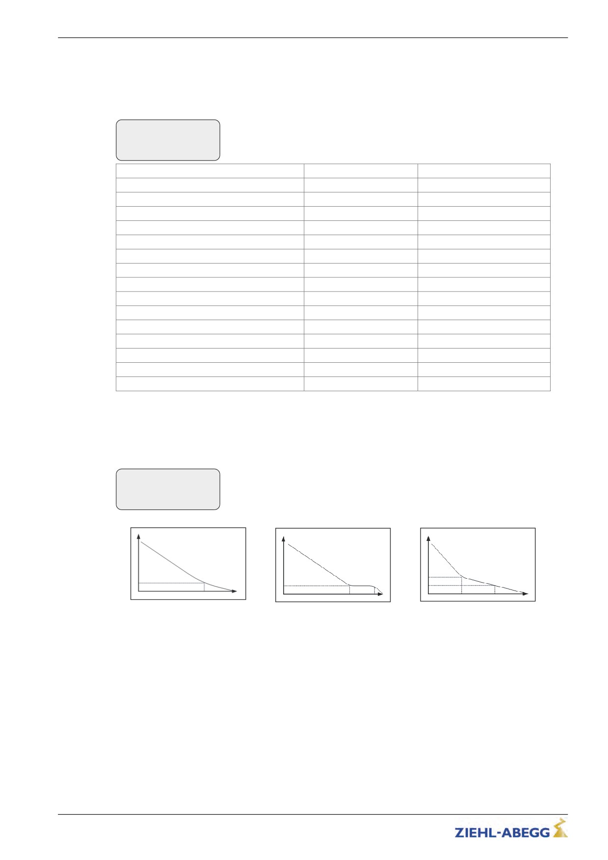
The behavior during direct leveling (only in DCP_02 and DCP_04) can be set in the DECELERA-
TION/S_ABH menu.
Delay
|-" S_ABH
DCP_comf
|-"
DCP_slow
Distance dependency
S_ABH=DCP_fast
S_ABH=DCP_comf
S_ABH=DCP_slow
Time optimized leveling
Leveling with short crawl path
Leveling with early reduction of the
leveling speed
61/200
Serial communication
9.2
CANopenLift
9.2.1
Start-up the CAN-interface
9.2.1.1
Information for start-up
Caution
Incorrectly wired connections can destroy the electrical / electronic components. Electrostatic
CAUTION!
discharges can be hazardous to the electronic components and lead to errors in the software.
9.2.1.2
Frequency inverter
• To operate the installation with CANopen, the frequency inverter must be equipped with the
optional board EM3-EMC-CAN-DCP (Art.-No.3357107).
• Only devices with the CiA 417 profile are allowed.
• All devices work in 11 bit - mode.
• By implication, there can be one ZETADYN 3 connected to one bus-system.
• When two ZETADYN 3 per bus-system are needed, please call ZIEHL-ABEGG before installing.
9.2.1.3
Bus-cable
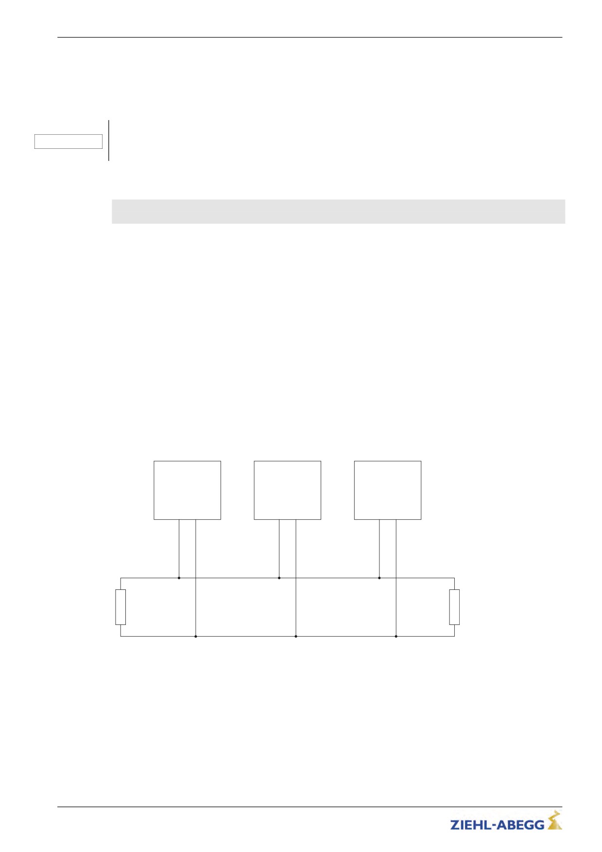
• A shielded bus-cable is not needed, but the data wires should be twisted.
• The installation takes place in line structure. The seperate devices are connected to the bus with
short branch lines.
• The bus should be terminated with a terminating resistor of 120 - 150 Ohms, at both ends of the
bus.
• The maximum length of the bus is 200 m and 6 m at the branch lines.
• All devices normally work with a baud rate of 250 kBit/s.
9.2.1.4
Wiring
• The connection of the bus cable takes place at the slot "X-CAN" of the frequency inverter.
• Take care of the maximum bus length.
• Not correctly shielded motor- , brake chopper- or brake resistor cables can cause significant errors.
• In case of an error, check the shielding of the cables.
Steuerung /
Umrichter /
Schachtgeber /
Control system
Inverter
Encoder
120 - 150 Ohm
120 - 150 Ohm
Exemplary assembly of a bus-system with CANopen
62/200
Serial communication
9.2.1.5
Electrical connection
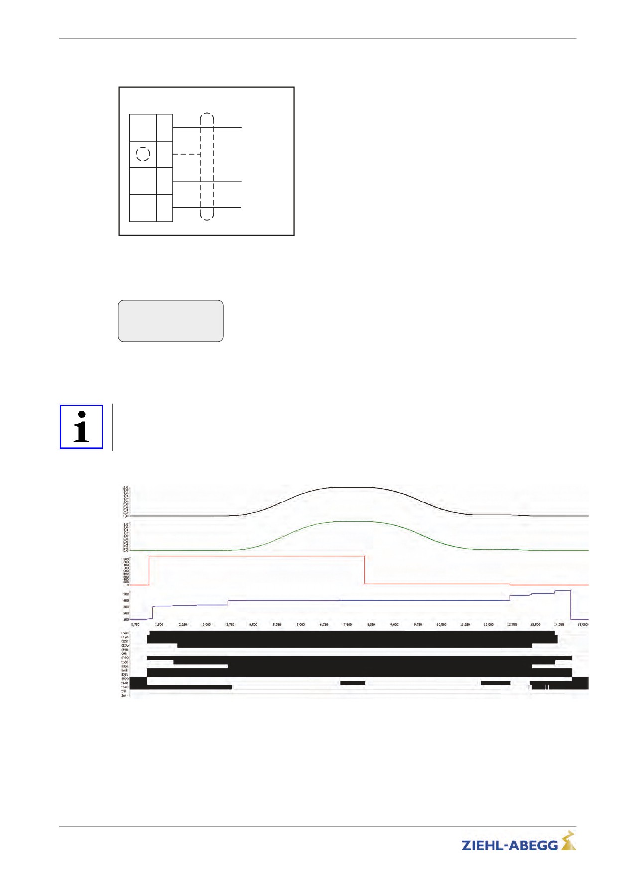
The connection of the bus cable takes place at the slot X-CAN of the frequency inverter.
X-CAN
CH
(4)
CAN High (H)
Optionaler
(3)
Schirmanschluss
CL
(2)
CAN Low (L)
0VC
(1)
GND
Connection CAN
9.2.1.6
Activating the interface
The activation of the CAN interface can be set in the menu Control system/CONFIG.
Control
|-" CONFIG
01:BP_DCP1
|-"
02:BP_DCP2
Configuration
The INFO menu shows CAN information at the pages 14 - 17 (Assumption: "CONFIG" = "02:
ZA_CAN").
9.2.1.7
Operation modes
Information
For the ZETADYN 3 are two operation modes by using CAN:
• Velocity Mode (Velocity Mode [pv])
Velocity Mode
63/200
Serial communication
• Position Mode (Position Mode [pp]
Position Mode
The used mode can be set in the menu "CAN/MODE" of the ZETADYN 3. Generally the mode is sent
from the control system to the ZETADYN 3 shortly before start-up. Therefor you have to set the
operation mode in the control system.
When the ZETADYN 3 is operated in position mode, the shaft-encoder has to be connected to the
same bus as the ZETADYN 3.
The control system transmits the travel speed to the frequency inverter before every drive. If the
transmitted speed couldn't be reached, the frequency inverter initiates a pointed arch drive. Therefor
the maximum speed has to be entered in the control system.
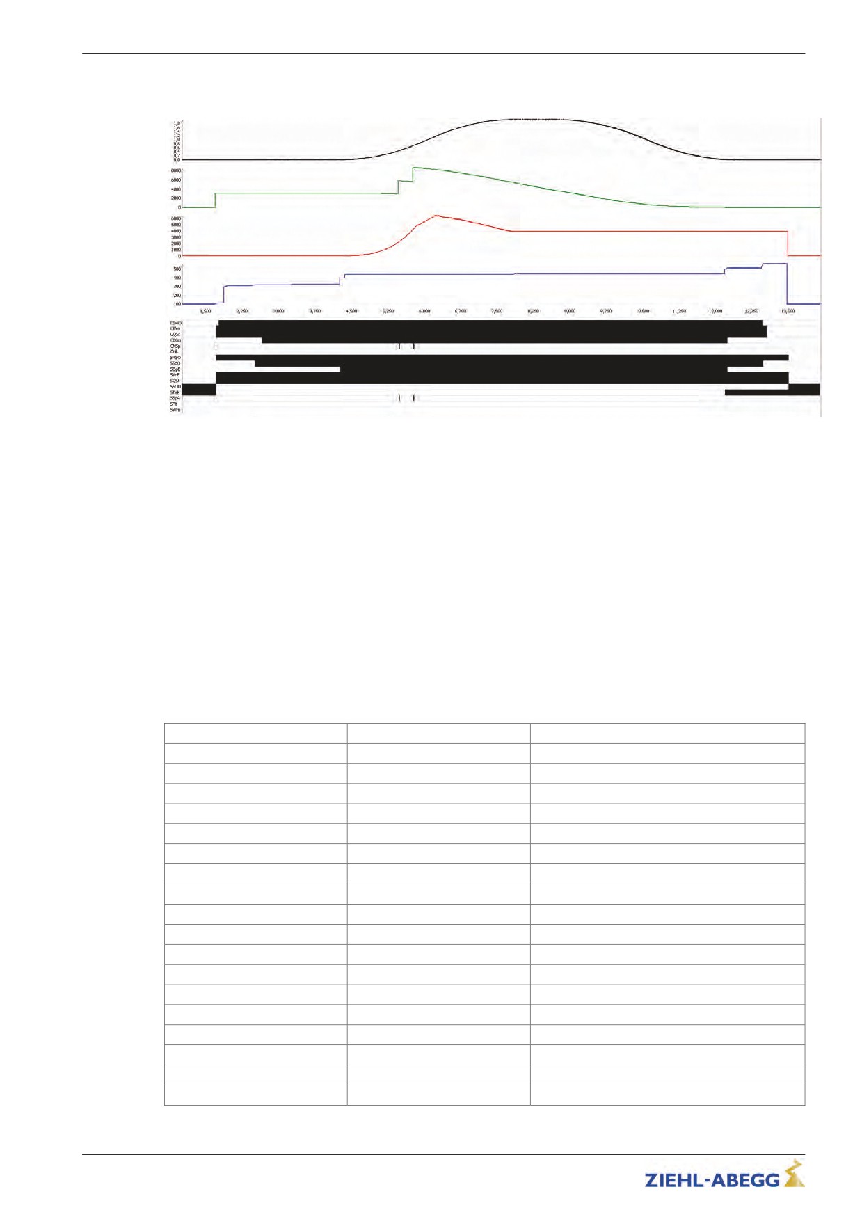
9.2.1.8
Command- and Statusbits of the recorder
• Position Mode [pp] C&S / Velocity Mode [pv] C&S
• C = Command = Command from the control system to the frequency inverter
• S = Status = Status of the frequency inverter as reaction of a command from the control system
Status- / Commandbit
Description
Remarks
CSwO
Command Switch On
CEVo
Command Enable Voltage
CQSt
Command Quick Stop
CEOp
Command Enable Operation
CFaR
Command Fault Reset
CNSp
Command New Setpoint
only active in position mode
CHlt
Command Halt
SRSO
Status Ready to Switch On
SSdO
Status Switched On
SOpE
Status Operation Enabled
SVoE
Status Voltage Enabled
SQSt
Status Quick Stop
SSOD
Status Switch On Disabled
STaR
Status Target Reached
SS=0
Status Speed = 0
only active in velocity mode
SSpA
Status Setpoint Acknowledge
only active in position mode
SFlt
Status Fault
SWrn
Status Warning
64/200
Serial communication
9.2.2
Parameter
9.2.2.1
Parameter settings
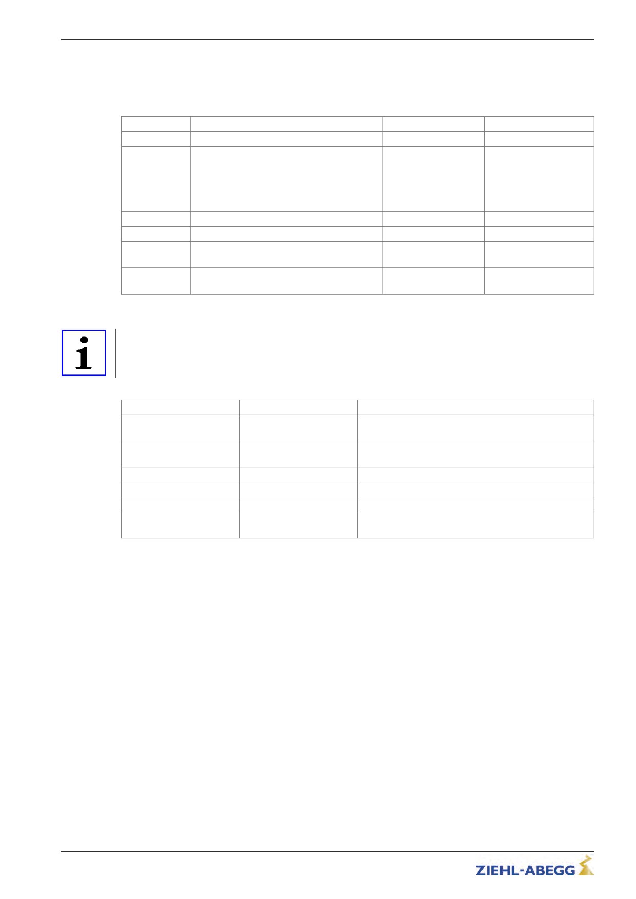
The seperate parameters for CAN operation can be modified in the menu CAN.
Parameter
Description
Value range
Factory setting
LIFT_NR
Enter the lift number
1 ... 2
1
NODE_ID
Node number,
1 ... 128
2
normally:
Control system: 1
Frequency inverter: 2
Encoder: 4
BD_RATE
Transmission rate (baud rate)
10 kBd ... 250 kBd
250 kBd
MODE
Operation mode of the ZETADYN 3
Position / Velocity
Position
T_CMD
Maximum waiting time for commands of the
200 ... 3000 ms
1500 ms
control system
T_MAX
Maximum processing time for the CAN mes-
0,1 ... 3 ms
0.8 ms
sages per cycle.
The CAN-specific displays are in the Info menu on pages 14 - 17 (see chapter "Parameters List").
Information
The in the ZETADYN 3 adjusted nominal travel speed V* has to be equal or higher than the speed
which is sent to the ZETADYN 3 by the control system. Otherwise no drive takes place.
9.2.2.2
Network Management Status
Status:
BootUp:
ZETADYN 3 is switching to the bus
Stop:
ZETADYN 3 was stopped (normally by the control sys-
tem)
Preop.:
ZETADYN 3 can be parametrised, but before the it has
to be set to "operational".
Opera.:
ZETADYN 3 is ready, a drive can take place.
Controller State:
No Error:
No errors existent
Warn.Lim.:
Error counter exceed 127
Bus off:
Because of too many errors the device was switched
off the bus (Error counter > 255)
65/200
Parameter list
10
Parameter list
Information
Not all of the described paramters are freely accessible. The indication of the parameters depends on
the choosen functions and the adjustments of the frequency inverter.
The individual parameters are subdivided into various menus based on their functions.
10.1
Basic-Level
The Startup, Statistic and Memory Card menus are displayed in the basic level.
The Startup menu is only displayed in the basic level. The Statistic and Memory Card menus are
displayed in both the basic level and advanced level. They are described in the chapters "Parameters
List / Statistic Menu" and "Parameters List / Memory Card Menu". See the chapter "Operation and
Parameterisation / The different operating levels" for information about the basic level.
10.1.1
Startup menu
All the parameters required for first-time start-up are contained in the Start-up menu.
Factory set-
Parameter
Description
Value range
ting
LCD
Select the desired operating language.
Deutsch
The operating languages German and English are integrated
English
into the device as standard.
Nederland
A third operating language can be loaded with the memory card.
Espanol
The following folders must be saved on the memory card for
Türkce
this: 3BF\Update\Language
Italiano
Deutsch
Svenska
Czech
France
Polski
Po Russki
USR_LEV
User Level
Basic
Choice about the user level which is active on the ZETAPAD
Basic
Advanced
after starting the ZETADYN 3.
MOT_TYP
Enter the operated motor type
ASM
ASM:Asynchronous motor
SMxxx
SM132
SMxxx: Synchronous motor External product
SM160
SM132: ZIEHL-ABEGG synchronous motor type SM132
SM190
SM160: ZIEHL-ABEGG synchronous motor type SM160
SM200
SM190: ZIEHL-ABEGG synchronous motor type SM190
SM225
SM200: ZIEHL-ABEGG synchronous motor type SM200
SM250
SM225: ZIEHL-ABEGG synchronous motor type SM225
SM700
SM250: ZIEHL-ABEGG synchronous motor type SM250
SM860
SM700: ZIEHL-ABEGG synchronous motor type SM700
SM860: ZIEHL-ABEGG synchronous motor type SM860
n
Enter the motor's rated speed
10 ... 2990 rpm
0
f
Enter the motor's rated frequency
3.0 ... 125.0 Hz
0.1
I
Enter the motor's rated current
5.0 ... 140.0 A
0.0
U
Enter the motor's rated voltage
200 ... 460 V
0
Enter the motor's rated current
p
Enter the motor's rated power
1.0 ... 65.0 kW
0
cos phi
0.10 ... 1.0
0.88
Enter the motor's power factor (only for asynchronous motors)
TYP
Enter the motor's type of connection
Star
Star
Delta
66/200

Parameter list
Factory set-
Parameter
Description
Value range
ting
ENC_TYP
Enter the type of encoder used
EnDat/SSI: Absolute rotary encoder
Position information is transmitted either via SSI (synchronous
EnDat/SSI
serial interface) or EnDat protocol
HTL 10-30V
ERN1387: absolute encoder
TTL square
EnDat/SSI
Position information is transmitted by analog signal
TTL Sine
ERN1387
TTL Sine: 5 V encoder with sinusoidal signal
No ENC.
TTL Square: 5 V encoder with square-wave signal
HTL 10-30V:10-30 V encoder with square-wave signal
No ENC.: Open-loop-mode
ENC_INC
Enter encoder resolution (pulses/revolution)
64 ... 10000
2048
BC_TYP
Enter the used brake resistor or brake chopper
BR11: Brake resistor type BR11-A
BR11
BR50:Brake resistor type BR50
BR50
BR50+BR25: parallel connection of BR25 and BR50
BR50+BR25
BR50+BR50: parallel connection of 2 pieces BR50
BR50+BR50
BRxx: Brake resistor external product
BRxx
PFU: Power Feedback Unit
PFU
PFU+BR11: Power Feedback Unit + Brake resitor type BR11
PFU+BR11
PFU+BR11: Power Feedback Unit + Brake resitor type BR17
PFU+BR17
PFU+BR11: Power Feedback Unit + Brake resitor type BR25
PFU+BR25
PFU+BR11: Power Feedback Unit + Brake resitor type BR50
PFU+BR50
BR09-1: Brake-Resistor Type BR09-1
BR09-1
BR17
BR14: Brake resistor type BR14
BR14
BR100: Brake resistor type BR100
BR100
PFU+BRxx: Power Feedback Unit + Brake resitor external prod-
PFU+BRxx
uct
2* BR100
2*BR100: parallel connection of 2 pieces BR100
3* BR100
3* BR100: Parallel circuit of three BR100
BR17
BR17-1: Brake resistor type BR17
BR25
BR25-1: Brake resistor type BR25
BC25
BC25: Brake-Chopper type BC25
BC50
BC50: Brake-Chopper type BC50
BC100
BC100: Brake-Chopper type BC100
ZArec
ZArec: ZArec feedback unit
V*
Enter the installation rated speed
0.00 ... 3.0 m/s
1.00
n*
Motor speed at V*
MOD_n = direct: direct input of the motor speed at V*
10 ... 2990 rpm
0
MOD_n = calculate: Calculates the speed of the motor depend-
ent on: V*; __D; __iS;__; __i1 and __i2
__D
Enter the diameter of the traction sheave
0.06 ... 1.20 m
0.50
__iS
Enter the installation's type of suspension
1:1
2:1
3:1
4:1
1:1
5:1
6:1
7:1
8:1
__i1
Input of i1 of the gearbox ratio i1:i1
1 ... 650
38.00
__i2
Input of i2 of the gearbox ratio i1:i2
1 ... 1000
1
Q
Enter the elevator installation's rated load
100 ... 20000
600
F
Enter the car weight
100 ... 20000
1000
G
Enter the counterweight
0 ... 20000
1300
67/200

Parameter list
Factory set-
Parameter
Description
Value range
ting
CONFIG
Configuration of the digital inputs according to the used control
system and type of communication
00:Free: Outputs are freely configurable
00:Free
01:ZA_IO: ZIEHL-ABEGG standard actuation
01:ZA_IO
02:ZA_CAN: ZIEHL-ABEGG CAN
02:ZA_CAN
03:BP_IO: Böhnke+Partner standard control
03:BP_IO
04:BP_DCP1: Böhnke & Partner DCP1
04:BP_DCP1
05:BP_DCP2: Böhnke & Partner DCP2
05:BP_DCP2
06:BP_DCP3: Böhnke & Partner DCP3
06:BP_DCP3
07:BP_DCP4: Böhnke & Partner DCP4
07:BP_DCP4
08:KN_IO: Kollmorgen standard control
08:KN_IO
09:KN_DCP3:Kollmorgen DCP3
09:KN_DCP3
10:KN_DCP4: Kollmorgen DCP4
10:KN_DCP4
11:NL_IO: New Lift standard control
11:NL_IO
12:NL_DCP3: New Lift DCP3
12:NL_DCP3
13:SS_IO: Schneider Steuerungen standard control
13:SS_IO
14:SS_DCP3: Schneider Steuerungen DCP3
14:SS_DCP3
15:ZA_BIN: ZIEHL-ABEGG standard actuation with binary
15:ZA_BIN
speed specification
16:WL_IO
01:ZA_IO
16:WL_IO: Weber Lifttechnik standard control
17:WL_DCP1
17:WL_DCP1: Weber Lifttechnik DCP1
18:WL_DCP2
18:WL_DCP2 Weber Lifttechnik DCP2
19:WL_DCP3
19:WL_DCP3 Weber Lifttechnik DCP3
20:WL_DCP4
20:WL_DCP4 Weber Lifttechnik DCP4
21:ST_IO
21:ST_IO Strack Lift Automation standard control
22:ST_DCP3
22:ST_DCP3 Strack Lift Automation DCP3
23:ST_DCP4
23:ST_DCP4 Strack Lift Automation DCP4
24:CSILVA
24:CSILVA: Carlos Silva standard control
25:S+S
25:S+S: Schmitt+Sohn standard control
26:KW_DCP3
26:KW_DCP3: KW Aufzugstechnik DCP3
27:MAS_BIN
27: MAS_BIN: Masora standard control
28:Bucher_SATU
28: BU_SATU: Hydraulic elevator aggregate with Bucher-Ag-
gregat type Saturn ALPHA
29:Bucher_ORIO
29: BU_ORIO: Hydraulic elevator aggregate with Bucher-Aggre-
30:KS_IO
gat type Orion ALPHA
31:KL_IO
30: KS_IO: Georg Kühn Control systems standard control
32:S_SMART
31: KL_IO: Kleemann standard control
32: S_SMART: Schindler Smart standard control
MO_DR
Changing the rotating direction of the motor
It must be observed the with triggering the input RV1 the cabin
left
drives upwards
left
right
left: Rotary direction left
right: Rotary direction right
CO
Monitoring the travel contactors
Off: Contactor monitoring deactivated
OFF
CO1: Contactor monitoring is only implemented by input CO1
CO1
CO1
(series connection of the monitoring contacts)
CO1&CO2
CO1&CO2: Contactor monitoring is implemented by inputsCO1
and CO2 (individual monitoring of the monitoring contacts)
68/200

Parameter list
Factory set-
Parameter
Description
Value range
ting
BR
Motor brake monitoring
Input of number and function of the brake monitoring contacts
used
OFF:no brake monitoring connected
1*NC: 1x normally closed contact (Contact closed when brake
Off
currentless)
1*NC
2*NC: 2 x normally closed contact (Contact closed when brake
2*NC
currentless)
accordingly to
3*NC
3*NC: 3 x normally closed contact (Contact closed when brake
motor type
1*NO
currentless)
2*NO
1*NO: 1 x normally open (contact is open when brake current-
less)
3*NO
2*NO: 2 x normally open contact (contact is open when brake
currentless)
3*NO: 3 x normally open (contact is open when brake current-
less)
P1P2
Motor temperature monitoring
Off
Off: Temperature monitor deactivated
PTC
PTC: thermistor (PTC according to DIN 44082)
PTC
TC
TC: Thermal circuit breaker
KTY
KTY: Temperature sensor KTY84-130
K_START
Start gain
is automatically
Multiplicative factor for the parameter "Controller/SPD_KP"
1.0
limited
Increasing the PI controller during the start-up
SPD_KP
Multiplication factor to modify the calculated basic amplification
is automatically
1.0
SPD_C
limited
69/200

Parameter list
10.2
Advanced-Level
The menus of the advanced level are described below. See the chapter "Operation and Parameter-
isation / The different operating levels" for information about the advanced level.
10.2.1
LCD & Password menu
Selection the desired operating language. Protects the frequency inverter from access by third parties
by assigning a password.Modifying the parameters is only possible after entering the password. A
password is not factory set.
Factory set-
Parameter
Description
Value range
ting
LCD
Select the desired operating language.
Deutsch
The operating languages German and English are integrated
English
into the device as standard.
Nederland
A third operating language can be loaded with the memory card.
Espanol
The following folders must be saved on the memory card for
Türkce
this: 3BF\Update\Language
Italiano
Deutsch
Svenska
Czech
France
Polski
Po Russki
USR_LEV
User Level
Basic
Choice about the user level which is active on the ZETAPAD
Basic
Advanced
after starting the ZETADYN 3
PASSWD
Enter password.
0 ... 9999
0
0 = no password
PW_NEW
New password
0 ... 9999
0
A number between 0 and 9999 can be used as a password
PWCOD
Displays the password in coded form. If you lose the password,
Cannot be set
21689
please contact the manufacturer.
PW_CLR
Deleting the password
The password has to be entered correctly before
On
Off
ON: Delete password
Off
Off: no function
70/200
Parameter list
10.3
Motor name plate menu
Enter the motor data in accordance with the data on the motor name plate.
Information
The motor data must be configured before the first trip!
The procedure for entering the motor data is described in the "Commissioning" chapter.
Factory set-
Parameter
Description
Value range
ting
MOT_TYP
Enter the operated motor type
ASM
ASM:Asynchronous motor
SMxxx
SM132
SMxxx: Synchronous motor External product
SM160
SM132: ZIEHL-ABEGG synchronous motor type SM132
SM190
SM160: ZIEHL-ABEGG synchronous motor type SM160
SM200
SM190: ZIEHL-ABEGG synchronous motor type SM190
SM225
SM200: ZIEHL-ABEGG synchronous motor type SM200
SM250
SM225: ZIEHL-ABEGG synchronous motor type SM225
SM700
SM250: ZIEHL-ABEGG synchronous motor type SM250
SM860
SM700: ZIEHL-ABEGG synchronous motor type SM700
SM860: ZIEHL-ABEGG synchronous motor type SM860
n
Enter the motor's rated speed
10 ... 2990 rpm
0
f
Enter the motor's rated frequency
3.0 ... 125.0 Hz
0.1
p
Displays the number of pole pairs of the motor
nicht einstellbar
I
Enter the motor's rated current
5.0 ... 140.0 A
0.0
U
Enter the motor's rated voltage
200 ... 460 V
0
Enter the motor's rated current
P
Enter the motor's rated power
1.0 ... 65.0 kW
0
cos phi
0.10 ... 1.0
0.88
Enter the motor's power factor (only for asynchronous motors)
TYP
Enter the motor's type of connection
Star
Star
Delta
M_MAX
Maximum motor torque
0.2 ... 5.0
2.0
71/200
Parameter list
10.4
Encoder & BC menu
Enter:
•
Encoder type
•
Encoder resolution
•
used Brake-Chopper or Brake resistor type
Factory set-
Parameter
Description
Value range
ting
ENC_TYP
Enter the type of encoder used
EnDat/SSI: Absolute rotary encoder
Position information is transmitted either via SSI (synchronous
EnDat/SSI
serial interface) or EnDat protocol
HTL 10-30V
ERN1387: absolute encoder
TTL square
EnDat/SSI
Position information is transmitted by analog signal
TTL Sine
ERN1387
TTL Sine: 5V encoder with sinusoidal signal
No ENC.
TTL Square: 5V encoder with square-wave signal
HTL 10-30V: 10-30V encoder with square-wave signal
No ENC.: Open-loop-mode
ENC_INC
Enter encoder resolution (pulses/revolution)
64 ... 10000
2048
BC_TYP
Enter the used brake resistor or brake chopper
BR11: Brake resistor type BR11-A
BR11
BR50:Brake resistor type BR50
BR50
BR50+BR25: parallel connection of BR25 and BR50
BR50+BR25
BR50+BR50: parallel connection of 2 pieces BR50
BR50+BR50
BRxx: Brake resistor external product
BRxx
PFU: Power Feedback Unit
PFU
PFU+BR11: Power Feedback Unit + Brake resitor type BR11
PFU+BR11
PFU+BR11: Power Feedback Unit + Brake resitor type BR17
PFU+BR17
PFU+BR11: Power Feedback Unit + Brake resitor type BR25
PFU+BR25
PFU+BR11: Power Feedback Unit + Brake resitor type BR50
PFU+BR50
BR09-1: Brake-Resistor Type BR09-1
BR09-1
BR17
BR14: Brake resistor type BR14
BR14
BR100: Brake resistor type BR100
BR100
PFU+BRxx: Power Feedback Unit + Brake resitor external prod-
PFU+BRxx
uct
2* BR100
2*BR100: parallel connection of 2 pieces BR100
BR17
BR17-1: Brake resistor type BR17
BR25
BR25-1: Brake resistor type BR25
BC25
BC25: Brake-Chopper type BC25
BC50
BC50: Brake-Chopper type BC50
BC100
BC100: Brake-Chopper type BC100
ZArec
ZArec: ZArec feedback unit
R_BR
Enter resistance of brake resistor when third-party product used
4 ... 200 Ohm
64
("BC_TYP=BRxx")
P_BR
Enter rating performance when third-party product used
0.0 ... 65 kW
0.5
("BC_TYP=BRxx")
T_PFU
Input of time between end of run and activation of the output with
the PFU function
0 ... 600 s
0
Input 0: Function deactivated
72/200
Parameter list
10.5
Installation menu
Enter of installation specific data
Information
The installation data must be configured before the first trip!
The procedure for calculating the installation nominal speed and to preset the travel data is described
in the "Commissioning" chapter.
Factory set-
Parameter
Description
Value range
ting
V*
Enter the installation rated speed
0.00 ... 3.0 m/s
1.00
MOD_n*
Input type of the motor speed at installation rated speed
direct: manually input of V* and n*
direct
Calculate
Calculate: Calculates the speed of the motor dependent on: V*;
Calculate
__D; __iS;__; __i1 and __i2
n*
Motor speed at V*
MOD_n = direct: direct input of the motor speed at V*
10 ... 2990 rpm
0
MOD_n = calculate: Calculates the speed of the motor depend-
ent on: V*; __D; __iS;__; __i1 and __i2
__D
Enter the diameter of the traction sheave
0.06 ... 1.20 m
0.500
__iS
Enter the installation's type of suspension
1:1
2:1
3:1
4:1
1:1
5:1
6:1
7:1
8:1
__i1
Input of i1 of the gearbox ratio i1:i2
1 ... 650
38.00
__i2
Input of i2 of the gearbox ratio i1:i2
1 ... 1000
1
Q
Enter the elevator installation's rated load
100 ... 20000 kg
600
F
Enter the car weight
100 ... 20000 kg
1000
G
Enter the counterweight
0 ... 20000 kg
1300
73/200

Parameter list
10.6
Control system menu
Configuring of:
•
elevator control system
•
Digital inputs
•
Digital outputs
Factory set-
Parameter
Description
Value range
ting
CONFIG
Configuration of the digital inputs according to the used control
system and type of communication
00:Free: Outputs are freely configurable
00:Free
01:ZA_IO: ZIEHL-ABEGG standard actuation
01:ZA_IO
02:ZA_CAN: ZIEHL-ABEGG CAN
02:ZA_CAN
03:BP_IO: Böhnke+Partner standard control
03:BP_IO
04:BP_DCP1: Böhnke & Partner DCP1
04:BP_DCP1
05:BP_DCP2: Böhnke & Partner DCP2
05:BP_DCP2
06:BP_DCP3: Böhnke & Partner DCP3
06:BP_DCP3
07:BP_DCP4: Böhnke & Partner DCP4
07:BP_DCP4
08:KN_IO: Kollmorgen standard control
08:KN_IO
09:KN_DCP3:Kollmorgen DCP3
09:KN_DCP3
10:KN_DCP4: Kollmorgen DCP4
10:KN_DCP4
11:NL_IO: New Lift standard control
11:NL_IO
12:NL_DCP3: New Lift DCP3
12:NL_DCP3
13:SS_IO: Schneider Steuerungen standard control
13:SS_IO
14:SS_DCP3: Schneider Steuerungen DCP3
14:SS_DCP3
15:ZA_BIN: ZIEHL-ABEGG standard actuation with binary
15:ZA_BIN
speed specification
16:WL_IO
16:WL_IO: Weber Lifttechnik standard control
01:ZA_IO
17:WL_DCP1
17:WL_DCP1: Weber Lifttechnik DCP1
18:WL_DCP2
18:WL_DCP2 Weber Lifttechnik DCP2
19:WL_DCP3
19:WL_DCP3 Weber Lifttechnik DCP3
20:WL_DCP4
20:WL_DCP4 Weber Lifttechnik DCP4
21:ST_IO
21:ST_IO Strack Lift Automation standard control
22:ST_DCP3
22:ST_DCP3 Strack Lift Automation DCP3
23:ST_DCP4
23:ST_DCP4 Strack Lift Automation DCP4
24:CSILVA
24:CSILVA: Carlos Silva standard control
25:S+S
25:S+S: Schmitt+Sohn standard control
26:KW_DCP3
26:KW_DCP3: KW Aufzugstechnik DCP3
27:MAS_BIN
27: MAS_BIN: Masora standard control
28:Bucher_SATU
28: BU_SATU: Hydraulic elevator aggregate with Bucher-Ag-
29:Bucher_ORIO
gregat type Saturn ALPHA
29: BU_ORIO: Hydraulic elevator aggregate with Bucher-Aggre-
30:KS_IO
gat type Orion ALPHA
31:KL_IO
30: KS_IO: Georg Kühn Control systems standard control
32:S_SMART
31: KL_IO: Kleemann standard control
33:SS_DCP4
32: S_SMART: Schindler Smart standard control
33: SS_DCP4: Schneider controls DCP4
MO_DR
Changing the rotating direction of the motor
It must be observed the with triggering the input RV1 the cabin
left
drives upwards
left
right
left: Rotary direction left
right: Rotary direction right
CTRL
Select the communication between the inverter and the control
system under "CONFIG=Free"
Standard
Standard: Parallel connection
DCP01
DCP1: Communication by DCP01 protocol
DCP02
Standard
DCP2: Communication by DCP02 protocol
DCP03
DCP3: Communication by DCP03 protocol
DCP04
DCP4: Communication by DCP04 protocol
74/200

Parameter list
Factory set-
Parameter
Description
Value range
ting
f_I01
Configuration of the function of the digital inputs I01 … I08 under
00:Free
01:RF
"CONFIG=free" (For description of the functions, see table).
f_I02
01:RF
04:V1
Input I08 is free adjustable, independent of "CONFIG".
f_I03
02:RV1-UP
05:V2
03:RV2-DOWN
f_I04
06:V3
04:V1
f_I05
07:VZ
05:V2
f_I06
02:RV1-UP
06:V3
f_I07
03:RV2-DOW-
07:VZ
N
08:V4
f_I08
00:Free
09:V5
f_XBR1
Configuration of the function of the digital inputs for the brake
10:V6
20:BR1
monitoring BR1 ... BR4 (For description of the functions, see
f_XBR2
11:V7
21:BR2
table)
f_XBR3
12:PARA2
22:BR3
13:BIN0
f_XBR4
00:Free
14:BIN1
15:BIN2
16:DIR(1=UP)
17:v=0
18:RF+RV1
19:RF+RV2
20:BR1
21:BR2
22:BR3
23:BR4
24:SBIN0
25:SBIN1
26:SBIN2
27:MBIN0
28:MBIN1
29:MBIN2
30: STANDBY2
31:STEP+
32:STEP-
33:PFU_BR
34:HY_UP
35:HY_DOWN
36:/DELAY
37:DTE
38:RECORD
39:INV_A1
40:FKT.ana
41:Monitor
43: STANDBY1
44:ZR_RDY
75/200
Parameter list
Factory set-
Parameter
Description
Value range
ting
f_O1
Configuration of the function of the digital outputs O1 … O4
Off
Err
under "CONFIG=free" (For description of the functions, see
f_O2
MotContact
MB_Brake
table)
f_O3
RB-Invers
MotContact
V<V_G1
f_O4
V < V_G1
V<V_G2
f_PWM
Configuration of the function of the digital output PWM
V<1.1*V_3
ATTENTION! The PWM output does not have zero potential.
Warning
The GND potential of the internal 24 V mains supply is con-
nected!
Err
EVAC.Dir
MB_Brake
INV V<V_G1
INV V<V_G2
V=0
PFU
Info rope
TD_CNT ext.
ZR_EN
V_G1
Presetting of the limit value 1 when using the V<V_G1 parame-
0.03 ... 3.20 m/s
0.30
ter for a digital output
V_G2
Presetting of the limit value 2 when using the V<V_G2 parame-
0.03 ... 3.20 m/s
0.80
ter for a digital output
V_G3
Presetting of the limit value 3 (this information is only issued
0.03 ... 3.20 m/s
0.50
when using a DCP protocol)
SIM_V1
ON: Distance-dependent delay of V3 -> V1 or V2 -> V1 is carried
out if V1 is activated 100 ms after switching off V3 or V2 at the
latest
SIM_V1 must be activated to carry out a distance-dependent
On
Off
delay of V3 -> V1 or V2 -> V1 with binary speed specification
Off
Off: Distance-dependent delay of V3 -> V1 or V2 -> V1 is only
carried out if the positioning speed is already activated at the
time of deactivation of a high travelling speed (V3 or V2)
A_MAX
Delay in elevator emergency stop due to deactivation of the
1.00 m/s2
input with the function "/DELAY"
S_B_OFF
Additional braking offset
If the control system doesn't extend early enough, it can be
50 ... 160 mm
50
increased here
76/200

Parameter list
Parameter descriptions for digital inputs
Parameter
Function
Explanation
00:Free
Function not assigned
Activating the input is noneffective
Enable for the frequency inverter. This input must be triggered
01:RF
Controller enable
during the entire trip.
02:RV1
Direction preset UP
Travel direction "UP"
03:RV2
Direction prest DOWN
Travel direction "DOWN"
04:V1
Positioning speed
Speed to position the car to the stop point
05:V2
Intermediate speed
If necessary, the intermadiate speed for normal travel
06:V3
Travel speed V_3
High travel speed for normal travel
Speed for readjustment. Has precedence above all other
07:VZ
Readjustment speed
speeds!
08:V4
Additional speed 1
Additional speed for inspection and return operation
09:V5
Additional speed 2
Additional speed for inspection and return operation
10:V6
Additional speed 3
Additional speed for inspection and return operation
11:V7
Additional speed 4
Additional speed for inspection and return operation
12:PARA2
Switchover to 2nd parameter set
2nd parameter set is activated
Speed default through binary coding
13:BIN0
Binary input 0
Standard-configuration
Speed default through binary coding
14:BIN1
Binary input 1
Standard-configuration
Speed default through binary coding
15:BIN2
Binary input 2
Standard-configuration
Default for direction of travel when using one input
16:DIR
Direction default
1 signal: Direction of travel "UP"
0 signal: Direction of travel "DOWN"
17:v=0
Hold speed 0
When the motor brake is open, speed 0 is controlled
Controller enable and travel direction "UP" are triggered with
18:RF+RV1
Controller enable + travel direction UP
one input
Controller enable + travel direction
Controller enable and travel direction "DOWN" are triggered with
19:RF+RV2
DOWN
one input
20:BR1
Brake monitoring 1
Brake monitoring with unsing the input terminal X-IN
21:BR2
Brake monitoring 2
Brake monitoring with unsing the input terminal X-IN
22:BR3
Brake monitoring 3
Brake monitoring with unsing the input terminal X-IN
23:BR4
Brake monitoring 4
Brake monitoring with unsing the input terminal X-IN
Binary input 0
Speed default through binary coding
24:SBIN0
Configuration Schmitt+Sohn
Configuration Schmitt+Sohn
Binary input 1
Speed default through binary coding
25:SBIN1
Configuration Schmitt+Sohn
Configuration Schmitt+Sohn
Binary input 2
Speed default through binary coding
26:SBIN2
Configuration Schmitt+Sohn
Configuration Schmitt+Sohn
Binary input 0
Speed default through binary coding
27:MBIN0
Configuration Masora
Configuration Masora
Binary input 1
Speed default through binary coding
28:MBIN0
Configuration Masora
Configuration Masora
Binary input 2
Speed default through binary coding
29:MBIN0
Configuration Masora
Configuration Masora
Switching the ZETADYN 3C to Standby 2 function to save en-
30:STANDBY2
Standby 2
ergy
31:STEP+
Touch mode for special applications
Positive change
32:STEP-
Touch mode for special applications
Negative change
Function monitoring of the feedback unit when using a brake
33:PFU_BR
Power Feedback Unit + brake resistor
resistor in connection with a feedback unit
The input functions RF+RV1+V1 are activated simultaneously
Direction UP at hydraulic elevator with
34:HY_UP
when the input is activated
Bucher aggregate type Saturn ALPHA
only in ZETADYN 3xx-HY
77/200

Parameter list
Parameter
Function
Explanation
Direction DOWN at hydraulic elevator
The input functions RF+RV2+V1 are activated simultaneously
35:HY_DOWN
with Bucher aggregate type Saturn
when the input is activated
ALPHA and Orion ALPHA
only in ZETADYN 3xx-HY
When deactivating the input the motor is braked with the delay
36:/DELAY
Delay in emergency stop
set in the "Controller/A_MAX" menu
37:DTE
ZIEHL-ABEGG test function
Reserved for ZIEHL-ABEGG
Start or stop measurement by external signal
38:RECORD
Recorder function
Input activated: Measurement is active
Input deactivated: Measurement is stopped and saved
Direction UP at hydraulic elevator with
39:INV_A1
Inverting the analog target value A1
Bucher aggregate type Orion ALPHA
40:FKT.ana
ZIEHL-ABEGG test function
Reserved for ZIEHL-ABEGG
Monitoring function for manually evac-
41:Monitor
Shown evacuation direction and evacution speed
uation
With active input there is a deceleration after speed 0, even
Distance-dependent deceleration after
when travel speeds are activated.
42: LZ
standstill
The deceleration from travel speed V1 depends on the distance
programmed for the parameter S_10.
Switching the ZETADYN 3C to Standby 1 function to save en-
43:STANDBY1
Standby 1
ergy
44: ZR_RDY
ZArec ready
ZArec monitoring function
Parameter descriptions for digital outputs
Parameter
Function
Explanation
Off
Output has no function
Output is open all the time
Contact closes when the following signals are applied: Controller
Controller ready
MotContact
enable, traveling speed and direction default. When the contact
Switching the motor contactors
closes, the motor contactors must be switched immediately.
Contact opens when the following signals are applied: Controller
RB_Invers
Inverted function of "RB contactor"
enable, traveling speed and direction default.
Contact opens when the tolerance set in the "Control system"
V<V_G1
Speed monitoring
menu V_G1 is exceeded.
Contact opens when the tolerance set in the "Control system"
V<V_G2
Speed monitoring
menu V_G2 is exceeded.
Contact opens when the traveling speed V3 is exceeded by
V<1.1*V_3
Speed monitoring
10%.
Monitoring of the motor temperature and the temperature of the
power section.
Contact opens if a malfunction advance warning is present
Warning
Warning
because of an excess temperatur. The current trip will be trav-
eled to the end. The advance warning can be evaluated by the
open loop control and a new start can be prevented.
Err
Err
Contact is closed if no error is present in the frequency inverter.
Contact open: Car is lighter than counterweight
EVAC.DIR
Evacuation direction
Contact closed: car is heavier than counterweight
Contact closes after expiration of the magnetic flux creation
MB_Brake
Mechanical brake
time. When the contact close, the mechanical brake must be
immediately opened via an external contactor.
Contact closes when the limit value set in the "Control system"
INV V<V_G1
inverted function of "V<V_G1
menu V_G1 is exceeded.
Contact closes when the limit value set in the "Control system"
INV V<V_G2
inverted function of "V<V_G2
menu V_G2 is exceeded.
Contact opens at start of travel, when actual speed > 0 m/s
V=0
Speed = 0
Contact closes at the end of travel when actual speed = 0 m/s
and output for control mode contactor = 0
PFU
Recuperation unit
Switching the feedback unit to standby function to save energy
78/200

Parameter list
Parameter
Function
Explanation
Contact closes when the actual rope still can be used, for approx
Info rope
Rope-change necessary
1 year.
Contact stays close until the down-counter will be reset.
The output relay gives an impulse to the output at every travel
TD_CNT ext.
Monostable trigger circuit
direction change.
For connecting an external counter, e.g. in the control system
Closed Loop operation: Output becomes active when deceler-
ation from V3 actual speed < limit value V_G1.
SD
Speed monitoring
Open Loop operation: Output becomes active when decelera-
tion from V3 nominal speed < limit value V_G1.
Output becomes inactive as soon as actual/nominal speed = 0
Contact closes when the following signals are present: controller
ZR_EN
ZArec: Controller ready
enable, travelling speed and direction specification.
10.7
Monitoring menu
Configuring the monitoring functions
Factory set-
Parameter
Description
Value range
ting
MOD_ST
Behavior of the frequency inverter during fault
Lock function: If serious errors occur successively without a
flawless trip being carried out, it is possible to blocks the inverter.
The output "ST malfunction" remains open. If a flawless trip is
carried out, the error counter is reset to 0
Fix 2 Sec: no blocking function, the output configured on "ST"
drops for 2 seconds during a malfunction and then increases
again
Fix 2 s
Lock n.3: Block function after 3 malfunctions. Output "ST" re-
Lock n.3
Fix 2 s
mains dropped after the 3rd error
Lock n.2:
Lock2.n.2: Locking function after 2 faults. Output "ST" remains
Lock n.1
released after the second fault.
Lock n.1: Block function after 1 malfunction. Output "ST" re-
mains dropped after the 1st error.
The following notification text appears during a block function:
"ZETADYN block [OFF]".After pressing the "i" key, the device
returns back to normal operation. The errors that led to the block
are accordingly marked in the error list.
LOCKBR
Block at brake malfunction
The controller is locked in case of brake malfunctions if this
ON
OFF
parameter is switched on.
OFF
At CONFIG: 31:KL_IO LOCKBR is activated automatically
CO
Monitoring the travel contactors
Off: Contactor monitoring deactivated
OFF
CO1: Contactor monitoring is only implemented by input CO1
CO1
CO1
(series connection of the monitoring contacts)
CO1&CO2
CO1&CO2: Contactor monitoring is implemented by inputsCO1
and CO2 (individual monitoring of the monitoring contacts)
79/200