ZETADYN 3BF. Operating instruction (Part.-No. 00163264-GB 2/200) - page 3

Parameter list
Factory set-
Parameter
Description
Value range
ting
BR
Motor brake monitoring
Input of number and function of the brake monitoring contacts
used
OFF:no brake monitoring connected
1*NC: 1x normally closed contact (Contact closed when brake
currentless)
Off
2*NC: 2 x normally closed contact (Contact closed when brake
1*NC
currentless)
2*NC
3*NC: 3 x normally closed contact (Contact closed when brake
3*NC
currentless)
accordingly to
1*NO
1*NO: 1 x normally open (contact is open when brake current-
motor type
2*NO
less)
3*NO
2*NO: 2 x normally open contact (contact is open when brake
currentless)
4*NC
3*NO: 3 x normally open (contact is open when brake current-
4*NO
less)
4*NC: 4 x normally closed contact (Contact closed when brake
currentless)
4*NO: 4 x normally open (contact is open when brake current-
less)
P1P2
Motor temperature monitoring
Off
Off: Temperature monitor deactivated
PTC
PTC: thermistor (PTC according to DIN 44082)
PTC
TC
TC: Thermal circuit breaker
KTY
KTY: Temperature sensor KTY84-130
R_P1P2
Only accessible when P1P2=KTY is parameterised
Resistance value at which the motor temperature monitor re-
500 ... 5000 Ohm
1190
sponds
1190 Ohm = 130 °C motor temperature
T_ENC
Encoder check time
Time is started when the output signal "MB" is issued. If there no
0.5 ... 7.0 s
2.0
input signals from the pulse encoder are applied during this time,
the inverter goes into malfunction
T_CO
Debounce time of the motor contactor monitoring
Monitoring time of the contactor interruption. The final stage is
switched off when the contactor contacts are open for longer
0.00 ... 100.0 ms
0.2 s
than the time set in the T_CO parameter. The time T_CO is
0.00=Off
active in interruptions during travel, not in a normal stop. Only
accessible when contactor monitor is activated.
T_CDLY
Delay contactor monitor
When the contactor monitor is switched on (menu "Monitoring/-
CO") the reply must be available at the contactor monitor input
0.5 ... 7.0 s
1.5 s
within the time T_CDLY for the motor contactors to be closed
(start up) or open (stop).
T_BR
Debounce time for brake monitoring. The input signal is eval-
uated delayed by the time T_BR. Only accessible if the brake
0.01 ... 3.00 s
0.40
monitoring is activated.
S_MB
Maximum distance with MB=Off
If rotary encoder pulses are detected with the digital output "MB"
0.10 ... 1.00 m
0.50
is switched off, the inverter issues an error message if the
configured path is exceeded.
I_MAX
Protection against overload current depending on the nominal
current of the motor
20 ...180 %
180
If the configured value for "I_Max" (I x "I_MAX") is exceeded for
the time "T_I_MAX" the inverter issues an error message.
T_I_MAX
Overcurrent protection
If the value configured for time "T_I_MAX" in "I_MAX"
0.3 ... 10.0 s
5.0
(I x "I_MAX") is exceeded, the inverter issues an error message.
80/200

Parameter list
Factory set-
Parameter
Description
Value range
ting
APC
Automatic arameter control
Parameter values are checked for plausibility when entered. The
On
values are corrected or additional parameters changes if neces-
On
Off
sary (see chapter "Error Diagnosis / Automatic Parameter
Check")
MASK1
Error mask 1...5
0
MASK2
Suppression of up to five error messages through configuring
0
the corresponding error number in an error mask
MASK3
Error no.
0
MASK4
0
MASK5
0
10.8
Start menu
Chronological sequence from before the start of acceleration and optimization of the start-up behavior.
Factory set-
Parameter
Description
Value range
ting
M_START
Control action to optimize the starting behavior (see chapter
"Commissioning")
Off
Off: RPM control without gain at start (K_Start=1)
MOD1
MOD1:Speed control
MOD2
accordingly to
MOD2: Speed control + safety function
MOD3
motor type
MOD3:Speed + position control
MOD4
MOD2: Position control + safety function
MOD5
MOD5: Position control
K_START
Start gain
is automatically
Multiplicative factor for the parameter "Controller/SPD_KP"
1.0
limited
Increasing the PI controller during the start-up
T_0
Max. motor contactor switch-on time
Time during deactivated contactor monitoring ("Monitoring/CO=-
0.0 … 10.0 s
0.5
Off") menu from applying the travel signal up to supply the
contactors with current
T_0 real
Measured time that the contactors require to open
Cannot be set
0.0
T_1
Flux build-up time
Time to build-up the magnetic field in the motor (only with asyn-
0.1 … 10.0 s
0.1
chronous motors)
Value set to 0.0
0.0
T_2
Maximum brake opening time
After expiration of time "T_1", the brake must have opened with-
1.8,
in time "T2"
for MOT_-
TYP=SM250:
0.0 … 15.0 s
2.5
0.6
T_2 real
Gemessene Zeit, welche die Bremse zum Öffnen benötigt
Cannot be set
0.0
T_3
Hold speed V_T3
Within time T_3, the machine accelerates up to the speed con-
0.0 … 10.0 s
0.0
figured in V_T3
V_T3
Minimal speed to minimize starting jerk. Within time T_3, the
machine is accelerated up to speed V_T3, thus overcoming the
0 … 50 mm/s
0
static friction.
s_start
If the position of the machine changes during the start procedure
by the configured value, amplification K_START is switched off
0.1 … 30 mm
3.0
(only with M_START=MOD2/4)
BRK_DMP
Brake damping
AUS
EIN
EIN
81/200
Parameter list
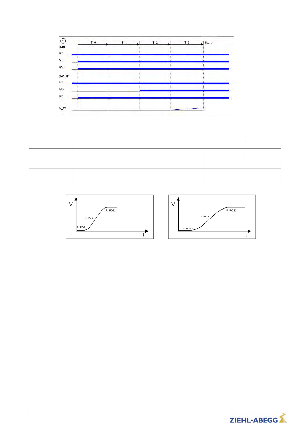
Start-up time sequence
10.9
Acceleration menu
Definition of acceleration ramp.
Parameter
Description
Value range
Factory setting
A_POS
Positive acceleration
0.25 ... 2.00 m/s²
0.5
R_POS1
Lower round off during positive acceleration, a higher value
will be calcu-
20 ... 90 %
causes a softer round off
lated
R_POS2
Upper round off during positive acceleration, a higher value
will be calcu-
20 ... 90 %
causes a softer round off
lated
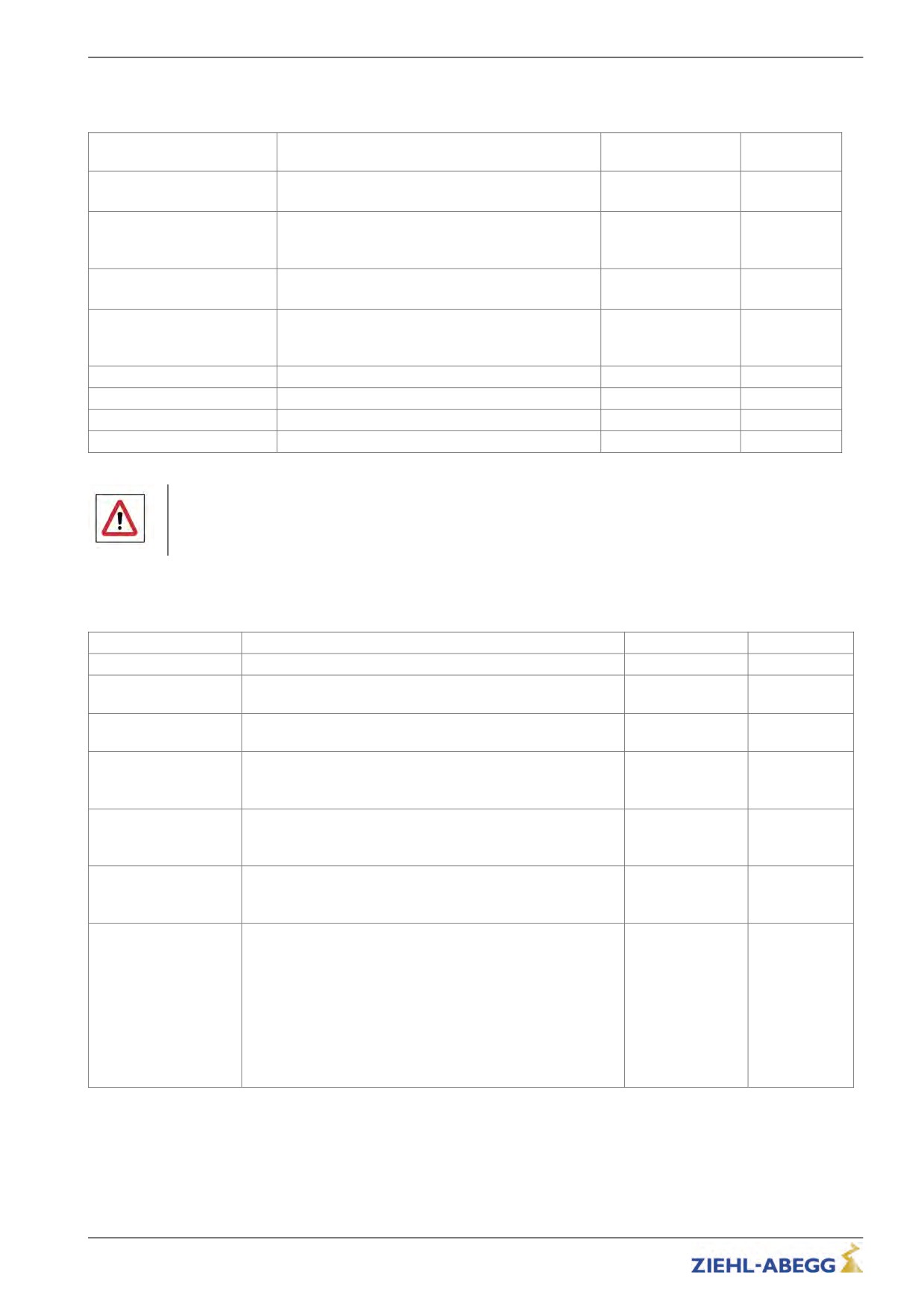
Acceleration with high A_POS and low R_POS1 and
Acceleration with low A_POS and high R_POS1 and
R_POS2
R_POS2
82/200
Parameter list
10.10
Travel menu
Traveling speed defaults
Factory set-
Parameter
Description
Value range
ting
V_1
Positioning speed
0.010 ... 0.20 m/s
0.050
Speed to position during floor approach
V_2
Intermediate speed
Speed for normal traveling e.g. during travel to inter-
0.03 ... 2.50 m/s
0.50
mediate floor
V_3
Travel Speed
0.03 ... 6.00 m/s
0.95
Speed for normal travel
V_Z
Readjustment speed
Speed for readjusting the car position during car
0.003 ... 0.30 m/s
0.01
loading or unloading
V_4
Additional speed
0.03 ... 3.00 m/s
0.30
V_5
Additional speed
0.03 ... 3.00 m/s
0.30
V_6
Additional speed
0.03 ... 3.00 m/s
0.05
V_7
Additional speed
0.03 ... 3.00 m/s
0.05
Danger!
Crashing of elevator car due to too long a delay path at high speed
Risk of death, severe injury and/or significant material damage
" Set the deceleration ramp so that the elevator car does not crash.
10.11
Decelerating menu
Defines the deceleration ramp and optimizes the positioning behavior.
Parameter
Description
Value range
Factory setting
A_NEG
Negative acceleration
0.25 ... 2.00 m/s²
0.5
R_NEG1
upper round off during negative acceleration, a higher value
will be calcu-
20 ... 90 %
causes a softer round off
lated
R_NEG2
lower round off during negative acceleration, a higher value
will be calcu-
20 ... 90 %
causes a softer round off
lated
S_DI3
Dist. correction V3
Traveling speed V_3 is switched off, delayed by the config-
0.00 ... 2.00 m
0
ured value
S_DI2
Dist. correction V2
Traveling speed V_2 is switched off, delayed by the config-
0.00 ... 2.00 m
0
ured value
S_DI1
Dist. correction V1
Traveling speed V_1 is switched off, delayed by the config-
0 ... 150 mm
0
ured value
S_ABH
Path dependent deceleration
ON: path dependent deceleration, the deceleration paths are
On
always identical
Off
OFF: time dependent deceleration, deceleration paths can be
DCP_fast
varied
On
DCP_comf
DCP_fast, DCP_comf, DCP_slow:Behavior during direct ap-
proach with DCP2 or DCP4 (see chapter "DCP mode" )
DCP_slow
V2toV3
V2toV3: in distance-dependent travel with intermediate speed
(V1 and V2 active) travelling speed V3 can be accelerated to
83/200
Parameter list
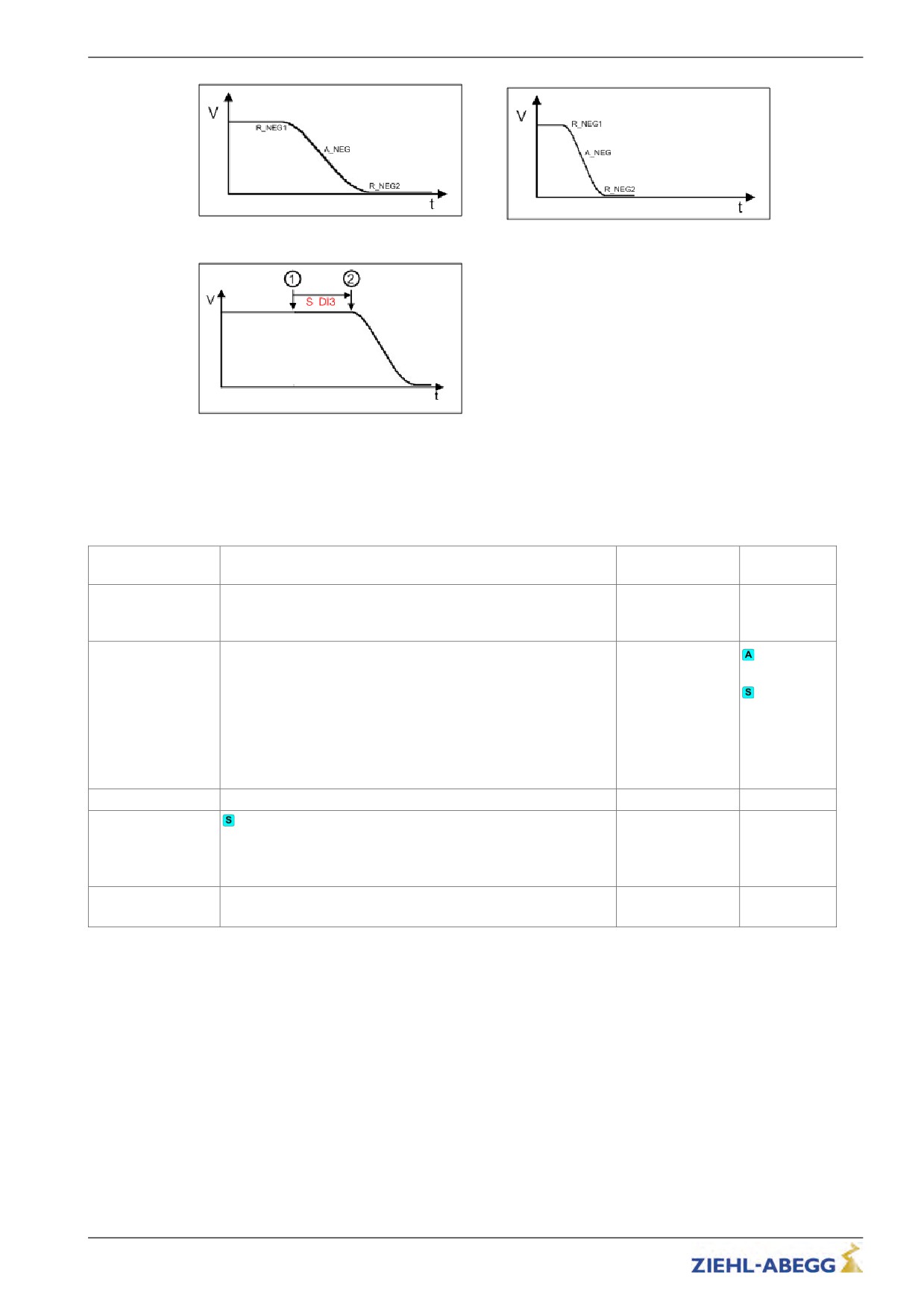
Deceleration with low A_NEG and high R_NEG1 and
Deceleration with high A_NEG and low R_NEG1 and
R_NEG2
R_NEG2
Function S_DI
1
Switching of V3
2
Starting with deceleration
10.12
Stop menu
Chronological sequence after reaching speed 0 during stopping procedure.
Factory set-
Parameter
Description
Value range
ting
T_4
Hold speed 0
During time T_4, the motor is maintained at speed 0 after reach-
0.0 ... 10.0 s
0.1
ing this speed
T_5
Mech. Brake close time
Time within which the mechanical brake must be closed
0.6
1.5,
0.0 ... 10.0 s
in the case of
MOT_-
TYP=SM250:
2.0
T_5a
additional current feed at closed brakes
0.0 … 2.0 s
0.0
T_5b
Wait until the motor is currentless
0.0 … 2.0 s
0.3
Within time T_5b, the powering of the synchronous motor is
decreased in a ramp function
T_6
Wait until contactors open
0.0 ... 10.0 s
0.5
Time within which the contactor signal must be closed
84/200
Parameter list
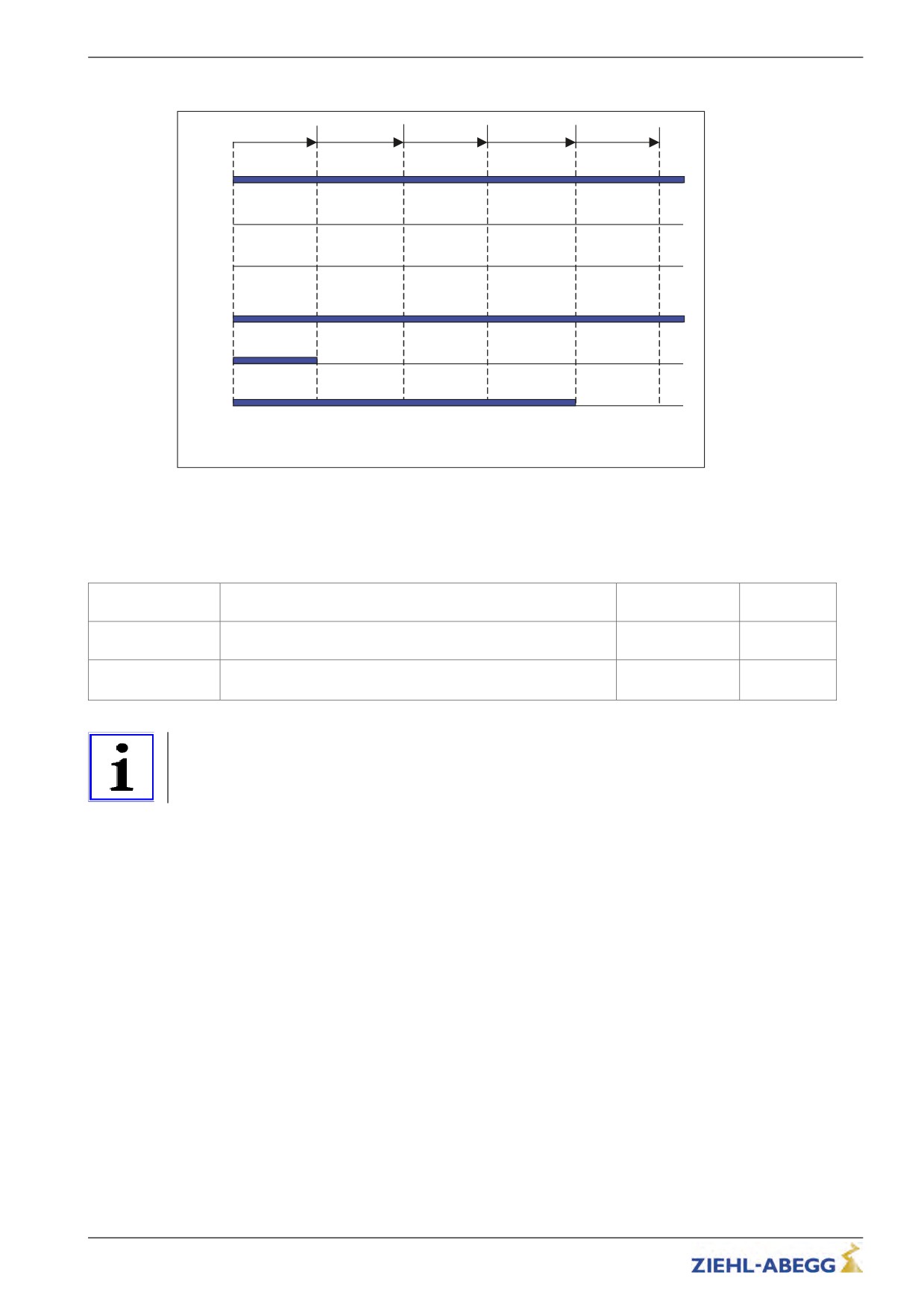
Stopping time sequence
T_4
T_5
T_5a
T_5b
T_6
X-IN
RF
Vx
RVx
X-OUT
St
MB
RB
10.13
Controller menu
Influences the speed control by the factor of the basic amplification (SPD_KP) and readjustment time
(SPD_TI).
Seletion of the operation mode of the frequency inverter
Factory set-
Parameter
Description
Value range
ting
SPD_KP
Multiplication factor to modify the calculated basic amplification
is automatically
1.00
SPD_C
limited
SPD_TI
Adjusting time
5 ... 300 ms
100
Controller averaging time during the trip
Information
The paramters which are necessary for the Open-Loop-operation are only displayd with the paramter
C_MOD=U/f. The parameters are described in the chapter Open-Loop-operation".
85/200

Parameter list
10.14
Parameter set 2 menu
A second set of parameters can be stored in the inverter. This can be used for:
•
Emergency evacuation
•
Normal travel with changed parameter values
•
Parameter back-up
Factory set-
Parameter
Description
Value range
ting
F_PAR2
Function allocation of parameter set 2
Locked: 2.nd parameter set is blocked
2.ndParameter set: Activates the 2.nd parameter set
Locked
EVAC 3: Emergency evacuation with evacuation module EVAC
2nd parameter set
3
EVAC 3
Locked
EVA. 3*AC: Emergency evacuation through three-phase current
EVA. 3*AC
emergency-generator
EVA. 1*AC
EVA. 1*AC: Emergency evacuation through UPS
UPS
UPS: Emergency evacuation through UPS (with decreased
power)
U_ACCU
Accu nominal voltage
Configuring the rated voltage of the rechargeable battery during
60 ... 565 V
120
evacuation with evacuation unit EVAC 3 ("f_PARA2=EVAC 3B",
see "Emergency evacuation" chapter)
P_UPS
Max. Load UPS
Configuring the available power of the UPS during evacuation
0.0 ... 70.0 kW
1.0
with UPS ("f_PARA2=UPS", see "Emergency evacuation" chap-
ter)
RS_UPS
Stator resistor
0.0 ... 9.99 Ohm
1.00
Enter the resistor of the stator of themotor with "f_PARA2=UPS"
STOP
Stop function to improve the positioning accuracy in the evacua-
tion mode "f_PARA2=UPS"
ON:
On
- Brake is closed when the switch point for V_1 is closed.
Off
Off
- Brake is closed when the residual path configured in S_STOP
has been reached (only for DCP02/04
Off: Stop function deactivated
Copy
Copy parameter set
OFF: Function deactivated
Off
Off
PARA1->2: copies the data from 1st parameter set into the 2nd
Para 1->2
parameter set
86/200
Parameter list
10.15
Statistic menu
All statistical data can be called up in the Statistic menu. The data remain saved even after the
frequency inverter has been switched off. Reading out the error list and deleting the error memory are
described in the "Error diagnosis" chapter.
Information
Not all parameters are visible when the Statistic menu is opened in the basic level.
visible in
Factory
Parameter
Description
Value range
the basic
setting
level
ST_LST
Error list
Cannot be set
-
X
ST_H
Operating hours
Cannot be set
-
X
ST_DRV
Number of trips
Cannot be set
-
X
ST_RES
Number of mains interruptions
Cannot be set
-
X
ST_SRF
Number of travel aborts due to interruption of the controller
Cannot be set
-
X
enable RF during the travel
ST_SCO
Number of trip aborts due to interruption of the contactor mon-
Cannot be set
-
X
itoring CO (opening of the contactor) during the travel
ST_CRL
Delete error memory
Cannot be set
-
Deletes ST_LST, ST_RES and ST_SRF and ST_SCO
APD
Automatic parameter diagnosis, see "Error diagnosis" chapter
On
On: Automatic parameter diagnostics are activated
Off
Off
Off: Automatic parameter diagnostics are deactivated
RESET
Deletes parameters, counter levels and error lists, preassigning
parameters with standard values.
RESET77:
preset parametred frequency inverter: Parameters will be set
with customer specific datas
Standard frequency inverter: Parameters will be set with
Reset 77
standard data
Reset 90
0
X
RESET90: Device reset, parameters remain preserved. ENC_-
OFF stays.
Reset 99
RESET99: Device reset, parameters deleted and assigned by
the factory settings.
If a value is entered for the encoder offset (ECOFF), it will also
be deleted!
TD_PWN
Assign password for the travel direction counter.
0 ... 9999
0
A number between 0 and 9999 can be used as a password
TD_PWC
Displays the password in coded form. If you lose the password,
nicht einstellbar
21689
please contact the manufacturer.
TD_PW
Enter password.
0 ... 9999
0
0 = no password
TD_CNT
Initial value of the down counter
0.00 ... 10.00 M
0.00
87/200

Parameter list
10.16
Memory Card menu
Contains the parameters for the various functions in association with a memory card.
Information
Not all parameters are visible when the Memory Card menu is opened in the basic level.
visible in
Factory
Parameter
Description
Value range
the basic
setting
level
SAV_ALL
Saves data to memory card with serial number allocation
• Parameter list (.PRT) in directory /3BF/DEVICE/serieal
number/LST
• Error list (.FLT) in directory /3BF/DEVICE/serial number/LST
• Parameter (.PA3) in directory /3BF/DEVICE/serial num-
On
ber/LST
Off
X
Off
• Black-Box (.BOX) in directory /3BF/DEVICE/serial num-
ber/LST
Off: no function
ON: Data will be saved to the memory card. After copying, the
parameter jumps back to "Off"
SAV_PAR
Save parameters to memory card (copy parameters in the case
of identical systems):
• Parameter (.PA3) in directory /3BF/DEVICE/FORCE
Here, there is no serial number allocation. The data will be over-
On
Off
X
written during each saving
Off
Off: no function
ON: Parameter will be saved to the memory card. After copying,
the parameter jumps back to "Off"
LOD_PAR
Load parameters from memory card to inverter (copy parame-
ters in the case of identical systems)
Enter 27: Parameter (.PA3) will be loaded from the /3BF/DEVI-
27
0
X
CE/FORCE directory into the inverter After loading, the parame-
ter jumps back to "off"
UPDATE
Starts the software update from a memory card. The most cur-
rent software will always be loaded from the memory card.
27
0
Enter 27: Software will be loaded from the /3BF/Update/Softwar-
eversion directory into the inverter
SAV_CFG
Saves data to memory card with configuration number alloca-
tion:
• Parameter list (.PRT) in directory /3BF/CONFIG/configuration
0 ... 59999
0
• Parameter (.PA3) in directory /3BF/CONFIG/configuration
number
LOD_CFG
Load parameter from memory card to converter with specifica-
tion of configuration number
Enter configuration number : Parameters (.PA3) are loaded to
0 ... 59999
0
the converter from the /3BF/CONFIG directory. The parameter
jumps to "Off" again after loading
Format
Reformatting the memory card:
27
0
Enter 27:Folders and files on the memory card will be deleted
88/200

Parameter list
10.17
MMC-Recorder menue
With the assistance of the memory card it is possible to make measurements on the frequency inverter
without notbook. the measurement will be configurated in the MMC-Recorder menu.
Factory set-
Parameter
Description
Value range
ting
REC_MOD
Recorder settings
Off:Recorder is switched off
ON: Recorder ist active, the operating curves are saved to the
memory card
Off
Stop&Shot: Manual stopping and saving of a measurement
On
ZETAMON
which was started with MOD=ON". After saving the data on the
Stop&Shot
memory card, REC_MOD will set to "Off".
ZETAMON
ZETAMON: Mode for using ZETAMON software
The settings for REC_MOD can only be changed with
REC_CFG=0.
REC_CFG
Configuring the measurement channels
0
0: all measurement channels and the recording time can be
1
freely configured
2
1 … 9: permanently set configurations that cannot be modified
3
4
1
5
6
7
8
9
REC_NUM
Directory number
Number assignment for the file on the memor card. With entering
0
"0" the serial number of the inverter will be used for the name of
the file.
TRIG_BY
Trigger-source
Specifications for stopping the recorder and saving the data to
the memory card.
Error
1.0
Error: data will be saved as soon as an error occurs
Error/Stop
Err/stop: data will be saved as soon as an error occurs or an
error-free travel is finished
T_REC
Record-time
5 s
Time for 1000 measurements
10 s
For a recording time of 5 s, for example, measured values are
15 s
recorded every 5 ms
20 s
40 s
5
80 s
160 s
0.5 h
1 h
24 h
T_DLY
Trigger Delay
Delay time for stopping of the masurement, e.g. T_DLY=0.5s:
0.5 s
0.5 s
the recording will be stopped 0.5s after an error occurs.
89/200

Parameter list
Factory set-
Parameter
Description
Value range
ting
CHN1
Configuration of the measuring channels 1-4 with analog meas-
3
urement values
CHN2
0...299
1
1: setted speed [m/s]
CHN3
143
3: acutal speed [m/s]
CHN4
6: Internal status (inverter status)
16: flux build-up current [A]r
26: motor current [A]
27: motor voltage [V]
31: temperatur power section [°C]
49: covered total travel distance [m]
6
62: residual path by the control system [mm] (only wirh DCP2 or
DCP4)
119: Capacity of the Brake-Chopper / Brake resistor
142: Intermediate circuit voltage [V]
143: torque build-up current [A]
CHN5
Configuration of the measuring channel 5 with digital measure-
ment values
89: digital in- and outputs with indication of the function
0...299
89
90: digital in- and outputs optimized for brake monitoring
91: digital in- and outputs
92: DCP-order and statusbits
10.18
Encoder adjustment menu
Contains parameter values required for aligning the SSI/EnDat rotary encoders for synchronous
motors.
The procedure for entering the encoder alignment data is described in the "Special functions" chapter.
Factory set-
Parameter
Description
Value range
ting
ENC_ADJ
Activating the encoder alignment
Off: no function
On
Off
ON: Starts the encoder offset or control of the encoder offset
Off
alignment
ENC_POS
Encoder Position
Numerical display of the absolute position of the encoder per
Cannot be set
-
revolution:
0 … [4x number of grooves in encoder]-1
ENC_OFF
Encoder Offset
Shifts the zero position of the absolute rotary encoder to the
pole's electrical zero position
EnDat encoder: Default 0 is absolutely necessary
0 ... 360.00°
0
SSI encoder: if the SSI encoder is not mechanically mounted in
the zero position, the value ascertained during the offset align-
ment (ENC_ADJ) for ENC_OFF must be entered
90/200
Parameter list
10.19
Safety gear menu
Configuration of the data used for the "Safety gear" function.
The procedure for the safety brake is described in the "Special functions" chapter.
Factory set-
Parameter
Description
Value range
ting
SB_MOD
Activate or deactivate the capture release
OFF:Capture release is deactivated
On
On: Starting the Safety-Brake-function in the requested direction
Off
Off
by pressing the button "Inspection trip UP" oder "Inspection trip
DOWN"
SB_M
Default for pulse amplitude with which the motor is to be fed with
current.
10 ... 100 %
70
The default is made as a percent from the maximum inverter
operating current (rated current x 1.8)
SB_T0
Pulse breake
0.1 ... 2.0 s
0.2
Break time between the individual current pulses
SB_T1
Împulse time
0.1 ... 1.0 s
0.5
Time for which the motor will be fed with current
SB_N
Number of current pulses
1 ... 5
3
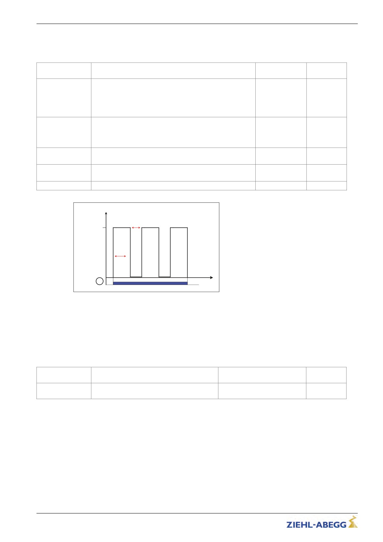
SB_N=3
SB_M [%]
SB_T0
100
SB_T1
1
t
Process capture release
1
Inspection trip "UP" or "DOWN"
10.20
HW-Ident. menu
Identification of the individual assemblies in the frequency inverter. The identification of the assembly
is generally downloaded directly from its EEPROM.
Manual input of the identification defaults is only necessary in case of malfunctions and replacements.
To do so, enter the stored version number for the corresponding assembly.
If the number of the stored version numbers is exceeded, a 0 = automatic identification is entered.
Factory set-
Parameter
Description
Value range
ting
ID_NOK
The number of the changed hardware identifica-
tion (identification-no. unequal 0) is indicated
91/200

Parameter list
10.21
Power section menu
Configuring the tolerances of the internal power stage.
Factory set-
Parameter
Description
Value range
ting
M_PWM
Pulse width modulation operating mode
Auto: PWM frequency is changed depending on the power
stage temperature and load.
At the start of travel, the motor voltage is cycled at the cycle
Auto
Auto
frequency set in parameter "f_PWM_H".
Fix f_PWM
Cycle frequency is reduced if required.
Fix f_PWM: motor voltage is permanently cycled at the PWM
frequency set in the parameter "f_PWM"
f_PWM
Cycle frequency at parameter setting "M_PWM=Fix f_PWM"
2.5 ... 10.0 kHz
8.0
f_PWM_H
Maximum cycle frequency (start frequency) at parameter setting
"M_PWM=Auto"
2.5 ... 16.0 kHz
16.0
Parameter is only shown for "M_PWM=Auto".
UDC_N
DC voltage for the DC-link
100 ... 600 V
565
UDC_MIN
Minimum limit value of the DC-link voltage
30 ... 500 V
450
UDC_MAX
Maximum limit value of the DC-link voltage
300 ... 800 V
760
FAN_T
Power stage temperature at which the fan is switched on
28 ... 45 °C
33
10.22
Menu checks
Selection of supporting tests during acceptance of the system:
• Testing of the protection device according to EN81-A3
Factory set-
Parameter
Description
Value range
ting
SCY_EN
Enabling of the test functions
On: Functions are accessible
On
Off: No access to the functions
Off
Off
After a test function has been performed, this parameter
automatically adopts the "Off" value.
SCY_A3
Testing the protection device according to EN81-A3 for protec-
tion against accidental movement of the car
No current
No current: Movement of the car by releasing the brakes with-
Off
Off
out power to the final stage
Off: Function deactivated
10.23
CAN menu
Parametrize the CAN-specific functions.
Factory set-
Parameter
Description
Value range
ting
LIFT_NR
Enter the lift number
1 ... 2
1
NODE_ID
Node number, normally:
Control system: 1
1 ... 128
2
Frequency inverter: 2
Encoder: 4
BD_RATE
Bitrate
10 kBd ... 250 kBd
250 kBd
MODE
Operation mode of the ZETADYN 3
Position / Velocity
Position
T_CMD
Maximum waiting time for commands of the control system
200 ... 3000 ms
1500 ms
92/200

Parameter list
10.24
ZA-Intern menu
Parameterisation of internal measuring and monitoring functions
Factory set-
Parameter
Description
Value range
ting
PW_S9
Password for the indication of additional parameter
0
UVW_CHK
Definition of motor phase checking on start-up
Single:1.Motor phases will be check with the first travel after
switching-on the inverter. With a successful control no more
Single
further examination is made.
Cont
Single
If the examination is incorrect, with each start an examination is
made until a correct examination could be accomplished.
Off
Cont: Motor phases will be check with each travel
Off: Checking of the motor phases is deactivated
UVW_PEK
Test voltage for motor phase check
1 ... 10 V: Selection of the test voltage between 1 V and 10 V.
In case of an error the testing voltage is displayed in the error
1 ... 10 V
message.
15 V
f(P)
15 V:Test voltage 15 V.
f(P)
f(P): The testing voltage depends on the nominal voltage of the
motor, which is entered in the menu "Motor name plate". In case
of an error the testing voltage is displayed in the error message.
n_ANA
Initialisation value for analogue input in ZETADYN 3-HY
Example:
n_ANA = 3000
1 ... 3300
3000
analogue input = 0-10 V
10 V = 3000 1/min
93/200
Parameter list
10.25
INFO menu
The INFO menu provides an easily accessible overview of:
• Current measurements
• Current operation conditions of the inverter
• Current switching states of the inputs and outputs
• Inverter internal measurements
• Information about the internal components
The individual pages are numbered for increased clarity.
Page 01: Serial-No.
Line 2:
Serial No. - - - - - - - 01
ZETADYN 3BF013-A
Indication of the inverter type and inverter size
SN: 06128238/x001
-A: Typ ZETADYN 3BF for asynchronous motors
3.24-110308xx
-S: Typ ZETADYN 3BF für synchronous motors
-SD:Typ ZETADYN 3C with integrated brake contactors for synchronous machines
-X: unknown type
Line 3:
Serial number/type consecutively numbered
/0xxx: type ZETADYN 3BF
/Dxxx:Type ZETADYN 3C with integrated brake contactors for synchronous machines
Line 4:
Software version
Loaded 3rd operating language
Page 02: Status
Line 2:
Status - - - - - - - - - - 02
current service condition in plain text display
" System OFF 3
530R540R550R560R 100
Line 3:
^0.00 0.00 0.00m/s
last 5 service conditions
current operating condition is displayed on right
in total, the last 60 service conditions can be inquired:
Previous page
Next page
The current condition will be indicated with the arrows > <
The previous conditions are indicated with the arrows < >
Line 4 (from left to right):
current direction of travel
current position of car in the shaft
current travel path with positioning speed
current traveling speed
Page 03: Dist
Line 2:
Dist. - - - - - - - - - - -
03
sa: current position of car in the shaft
sa: 0.00 s21: 0.52m
sr:^0.00 s31: 1.45m
s21: calculated deceleration path V_2 R V_1
s1: 0.00 sd: 0.52m
s20: calculated deceleration path V_2 R Standstill (only in DCP02/DCP04)
Line 3:
sr: current direction of travel, current total route
s31: calculated deceleration path V_3 R V_1
s30: calculated deceleration path V_3 R Standstill (only in DCP02/DCP04)
Line 4:
s1: current travel path with positioning speed V_1 (not used in DCP02 / DCP04)
sd:real deceleration path V_3 R V_1 or V_2 R V_1
button.
94/200

Parameter list
Page 04: Mot
Line 2:
Mot - - - - - - - - - - - -
04
zzz _ _ _ _ _ _ _+0%
Bar chart of motor speed
real: 0rpm 0V
Slip in %
prog: 0rpm +0.0A
Load angle in °
Line 3:
Actual motor speed
Motor voltage
Line 4:
Target motor speed
Motor current
If the motor has been correctly adjusted, the slip is nearly proportional to the motor’s rated
current (e.g. 50% motor current = 50% slip).
button.
Page 05: MotDat
Display of the motor data entered in the “Motor name plate” menu:
MotDat - - - - - - - - - -
05
I: 11.0A n: 60rp
U: 360V f:10Hz
Line 2:
p: 10
Rated current
Nominal speed
Line 3:
Nominal voltage
Rated frequency
Line 4:
Number of pole pairs
Line 2:
MotDat - - - - - - - - - -
05
Rated current
I: 11.0A n: 1450rp
Nominal speed
cos:0.88 f: 50.0Hz
Line 3:
I0: 3.8A TR: 316ms
cos phi
Rated frequency
Line 4:
Magnetization current
Rotor time constant
Page 05: MotDatFW
Display of the calculated motor data with field weakening operation:
MotDatFW- - - - - - - - -
05
I: 11.0A n: 1560rp
cos:0.89 f: 53.4Hz
Line 2:
I0: 3.5A TR: 316ms
Rated current
Nominal speed
Line 3:
cos phi
Rated frequency
Line 4:
Magnetization current
Rotor time constant
Seite 05: MotDatNom
button, the original motor date wiill be displayed
MotDatNom - - - - - - - -
05
I: 11.0A n: 1450rp
cos:0.88 f: 50.0Hz
I0: 3.8A TR: 316ms
95/200

Parameter list
Page 06: RegLimits
Online display of whether a control loop has reached the limit
RegLimits - - - - - - - - 06
SP IQ ID PS U
Line 2:
LIM:.. ·
SP: Speed controller
PEK:
IQ: Current controller (torque creation current)
ID: Current controller (flux creation current)
PS: Position controller
U: Frequency-inverter voltage limit
Line 3:
Alarm bell left: minimum limit reached
Alarm bell right: maximum limit reached
No alarm bell should appear during a faultless, normal trip.
Page 07: Brake-Chopper
Online-display
Brake Chopper - - - - - 07
Line 2:
Internal 1.4kHz BC ·
U_DC:_ _ _ _ _ _ 565V
Internal PWM frequency (only for brake resistor)
Ampl:_ _ _ _ _ _ 0%
Condition of function and temperature monitoring on the input terminal BC (larger point = OK)
Line 3:
DC-link voltage as bar chart display
DC-link voltage
Line 4 (only with Brake resistor):
Modulation of Brake resistor as bar chart display
Modulation of Brake resistor in %
The DC-link voltage displayed in standstill must have the value “Mains connection
voltage x 1,41".
A large point must constantly be displayed behind the function and condition monitor.
button
Display will be frozen
Display of the loaf of the brake resistor (average value over 120s)
Page 08: Cu-Functions
Online-display
Cu-Functions- - - - - -
08
CONFIG 00: Frei
Line 2:
I:RF RV.2V
Selected control system configuration in menu "Control system/CONFIG"
O:
VG1
Line 3:
Active digital input functions:
• Controller enable (RF)
• Direction of travel (RV)
• Traveling speed (V)
Line 4:
Active digital output functions
Page 09: Start / Stop
Online display of the digital inputs and outputs important for the start / stop process:
Start/Stop - - - - - - -
09
Line 3:
RF RB CO MB BR1234
·
RF - Controller enable (input)
RB - Controller ready / Contactors switching (output)
CO - Contactor monitoring (input)
MB - mechanical brake switching (output)
BRx - Brake monitoring contacts
Line 4:
A big dot below the description displays the input or output is active
A "!" under the monitor input "CO" or "BR" indicates that this monitoring function has been
deactivated in the "Monitoring" menu.
96/200
Parameter list
Page 10: Cu-Ports
Online-display
Cu Ports
-------- 10
In: Out:
Line 3:
12345678 BC C12 1234
1…8: digital inputs I1…I8
........ ·
·
BC: Function and temperature monitoring of brake resistor or brake chopper
C12: Contactor monitoring
1…4: digital outputs O1…O4
Line 4:
A big dot below the description displays the input or output is active
Page 11: Encoder
Online-display
Encoder - - - - - - - - - 11
Line 2:
Incr:2048 Type:ENDAT
Enable·· Err: 0
Configured encoder resolution
Cnt:3941=345° A B
Detected encoder type (with absolute encoders)
Configured encoder type (with incremental encoders)
Line 3:
Enable first point: Enabling of the supply voltage for absolute rotary encoder
Enable second point: Absolute rotary encoder performance test
both points must be active
both points must be off
ERR: Error code from encoder, if the encoder is faultless, 0 must be displayed.
Line 4:
Cnt: Counter reading for impulse counter (0 - 4x encoder resolution) and display of motor
revolution in degrees (360° = one revolution of the motor)
A and B: graphic display of the sine signal (A) and cos signal (B)
button.
Page 12: Power1
Power stage condition (point for condition OK)
Power1 - - - - - - - - - -
12
Line 2 und 3:
DC IGBT PWM ED: 10%
··
·· ..
z FAN: 0%
DC:
UDC:565V
Temp: 28C
first point: Precharge relay switched on
second point: Power stage power supply
both points must be active during normal operation
IGBT:
first point: ower stage power supply
second point: Power stage power supply OK
both points must be active during normal operation
PWM:
first point: PWM power stage enabled
second point: Power stage power supply OK
Both points are only active during driving
Bar display under M:
narrow: Clock frequency 4 kHz fixed
medium: Clock frequency 8 kHz
wide: Clock frequency 16 kHz
ED:
Turn on duration of the frequency converter (time interval: 10 minutes)
FAN:
Speed of the fan in %
Line 4:
UDC: DC-link voltage
Temp: Power stage temperature
button.
97/200

Parameter list
Page 12: Power2
Cause for excess current malfunction
Power2 - - - - - - - - - - 13
ERR_EXT U. OC: ...
Line 2:
SRC_APP. UCE_P: ...
ERR_EXT: Excess current message (display is not saved; point is only displayed if excess
SRC_MOP. UCE_M:
current is present
U: Overvoltage error in the DC-link (voltage higher than 850 V DC)
OC: overcurrent was detected by the current sensors (incorrect phase is indicated by letters
U V W)
Line 3:
SRC_APP: Excess current is detected by the application processor.
UCE_P: Error in positive current path in power stage (faulty phase is displayed)
Line 4:
SRC_MOP: Excess current is detected by the motor management processor.
UCE_M: Error in negative current path in power stage (faulty phase is displayed)
During normal operation, no points and phase displays (U V W) should be active.
During a malfunction, the displays remain active until the next travel command (with the
exception of ERR_EXT)
Page 14: DCP-Ident
Information about the control system
DCP Ident - - - - - - - -
14
Info: xx
Line 2:
0101 / 010106 en
Manufacturer
Load: 77% - 12.3A
Line 3:
Software version of control system
Software date of the control system
Operating language set in the control system, display according to ISO639
The operating language of the inverter is automatically adapted.
Line 4 (only with DCP4):
Load in % (0% = cabin empty)
Load-dependent start torque current
Page 15: DCP-Bits
Online-display
DCP Bits
--------
15
Line 2:
B01..4... G
4...
S.1
6. 100
Command and speed bytes
CR UP V_3* MTW
B= command byte
G= speed byte
Line 3:
Status byte
S= Statusbyte
Current service condition in which the frequency inverter is operating
Line 4:
Display of the actual travel commands:
RF: Controller enable
Travel direction
controlled travel speed
MTW: Motor temperature pre-warning (displayed at overtemperature)
See chapter "Serial Communication / DCP (Drive Control & Position)" for further information
about DCP operation.
98/200
Parameter list
Display 1
Page 16: DCP-Dist.
Online-display
DCP-Dist. - - - - - - - - 16
sv_I7: +0002210mm
Line 2:
sv: +0002198mm
Display of the current remaining path
Prg:Rea 1.15:x.xxm/s
Line 3:
Display of the remaining path required
Display 2
Line 4:
Display 1:
DCP-Dist. - - - - - - - - 16
sv_I7: +0002210mm
Shows the ratio of set nominal speed to real speed.
sv: +0002198mm
Display during travel
Prg:Rea 1.15:1.10m/s
(providing that the controller supports the "I9" position telegram)
Display 2: Shows the ratio of set nominal speed to real speed.
Display after travel
(providing that the controller supports the "I9" position telegram)
Page 17: DCP-Err
Online display of transmission errors that increase the counter level during running operation
DCP Err - - - - - - - - - 17
as soon as transmission errors occur:
RX_TIM 1
Line 2:
RX_XOR 0
TX_ERR 0
RX_TIM: Timing (open loop control does not answer within the cycle time
Line 3:
RX_XOR: erroneous open loop control telegram is detected by inverter
Line 4:
TX_ERR: erroneous inverter telegram is detected by the open loop control
CAN--------------- - 14
Page 14: CAN
Act· Mode: Velocity
Information about CAN operation
T_max: 0 RErr: 0
Line 2:
NMT:Preop./Warn.Lim:
Act: A dot signalizes that the inverter operates with CAN
Mode: Operating mode (velocity or position)
Line 3:
T_max: Number of cycles, which excessed the maximum process time
RErr: Recieve buffer - error counter
Line 4:
NMT: Shows the actual NMT status (see chapter "Serial Communication / NMT")
button
CAN--------------- - 14
Line 3:
Act· Mode: Velocity
T_max: Maximum time for processing the CAN messges per cycle, since switch-on
T_max:0.7ms TErr: 0
TErr: Transmit buffer - error counter
NMT:Preop./Warn.Lim:
Page 15: CAN Velocity
Active in velocity mode
CAN Velocity------ - 15
Line 2:
V_CAN: + 0mm/s
Contr.:Disable Volt.
V_CAN: Travel speed, sent fron the control system to the ZETADYN 3.
Status:Sw. On Disab.
Line 3:
Contr. Control-byte. Shows commands which are sent by the control system
Line 4:
Status: Status-byte. Shows CAN-status of the ZETADYN 3
99/200
Parameter list
Page 15: CAN Position
Active in position mode
CAN Position------ - 15
S_CAN + 0mm
Line 2:
Contr.:Disab. Volt.
S_CAN: Relative target position, sent from the control system to the ZETADYN 3
Status:Sw.On Disab.
Line 3:
Contr. Control-byte. Shows commands which are sent by the control system
Line 4:
Status: Status-byte. Shows CAN-status of the ZETADYN 3
button the display shows the maximum travel speed, sent by the
control system
page 16: CAN Error information
Information about telegram errors in CANopen lift operation
CAN Error Info------ 16
Err act. Last:No Err
Line 2 (from left to right):
Rec Tra Warn Pas off
Error status
0 0 0 0 0
Load: Fault which last occurred
Displayed text:
Meaning
Error status
"Err act."
Error active
"Warning"
Warning
"Err pass"
Error passive
"Bus off"
Bus off
Load: Fault which last
"No Err"
no error
occurred
"Stuff"
Stuffing Error
"Form"
Form Error
"ACK"
Acknowledge Error
"Bit(r)"
Bit Error (Recessive Level was output but
Dominant Level detected)
"Bit(d)"
Bit Error (Dominant Level was output but
Recessive Level detected)
CRC Error
"CRC"
Line 3 and 4:
Rec: Number of receive errors
Tra: Number of transmit errors
Warn: Indication how often the frequency inverter switched to the warning status
Pas: Indication how often the frequency inverter switched to the error passive status
off: Indication how often the frequency inverter switched to the bus off status
Page 17: CAN Calib.
17
Calibration
CAN Calib.
1------ -
AbsEncmm: 5358
Lines 2 - 4:
MotEncmm:+ 4169
For calibrating the distances which were sent by the motor encoder and the shaft encoder.
Offs:13081A/M 1.28
Page 18: A&R
Display of configured values for:
A+R - - - - - - - - - - - -
18
0.62 0.62 m/s3
• Acceleration
0.50 0.50 m/s2
• Rampdown time
0.62 0.50m/s3
dependent on the operating curve of a normal ride
Line 2:
upper round off of the acceleration in m/s³
upper round off of the deceleration in m/s³
Line 3:
Acceleration in m/s³
Deceleration in m/s³
Line 4:
lower round off of the acceleration in m/s³
lower round off of the deceleration in m/s³
100/200

Parameter list
Page 19: InfoBus
Display of the inverter configuration
InfoBus - - - - - - - - -
19
Ident No 01234567
Line 2:
Exist: xxxx
Ident no. of the internal assemblies
Error 0000
0: Controller Unit (CU)
1: Shunt module (CUSH)
2: Expansion card DCP / CAN (CUEC)
3: Expansion card, encoder (CUEE)
4: reserved
5: Switching Power Print (SP)
6: Power Print (PP)
7: Module Print (MP)
Line 3:
Each board which implemented to the inverter will be indicated (see also "HW Ident." menu):
x: identification of the board by reading out the EEPROM
m: identification by manual default in the menu "HW-Ident."
Line 4:
Error allocation of the assembly
1: No answer
2: Incorrect or unknown object
3: No proper EEPROM connection
4: No or unknown part number
5: No or unknown index
6: Original and backup copy are not identical
During flawless operation, all internal assemblies must be displayed with a "0"
Page 20: TravelDirection
Display the direction changes
TravelDirection
---
20
TD_SET 10.00 M
Line 2:
TD_CNT 4.32 M
TD_SET: Initial value of the down counter
TD_DRV 18.45 M
Line 3:
TD_CNT: Travel direction counter, resettable.
Displays the remained travel direction changes with the actual rope.
After resetting the travel direction counter, TD_RES will be increased
Line 4:
TD_DRV: Total counter of the travel direction changes.
Value remains after resetting the down counter
TravelDirection
---
20
Page 20: TravelDirection
TD_RES 10
button, line 2 shows the actual number of counter resets "TD_RES".
TD_CNT 4.32 M
TD_DRV 18.45 M
Page 21: Cuec
Expansion board "Control"
Cuec
-----------
21
Type: B1013AA-02
Line 2:
Func: DCP & CAN
Type: Part number of the expansion board "Control"
Stat: GRN
Line 3:
Func: Functions of the expansion board "Control"
Line 4:
Stat: LED status of the expansion board "Control"
101/200
Travel options
11
Travel options
11.1
Normal travel
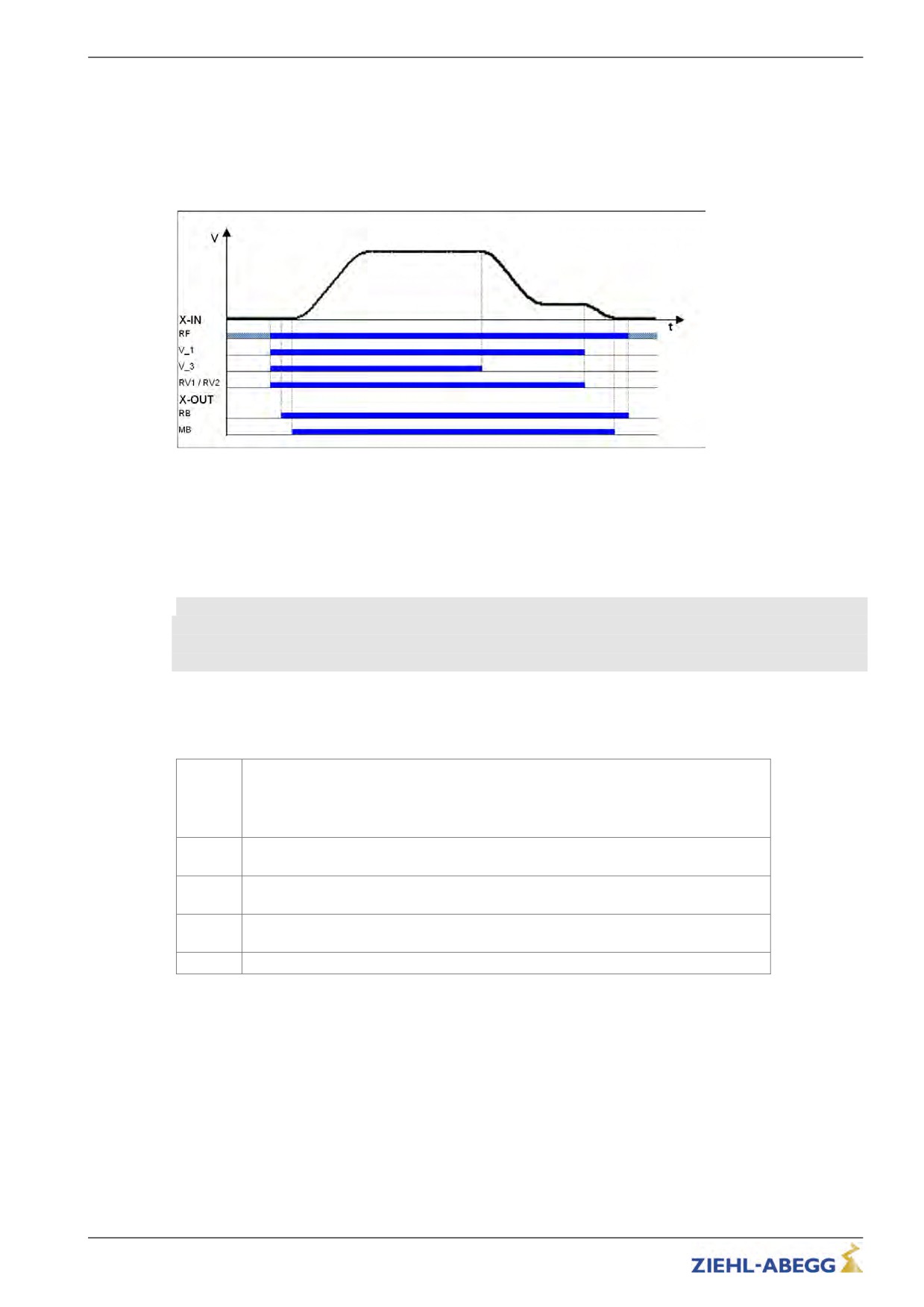
The figure shows the sequence of a trip between two floors with the corresponding input and output
signal processes. You can find a detailed description of the various acceleration and deceleration
processes in this chapter.
Normal travel
RF Controller enable
V_1
Positioning speed
V_3
Travel Speed
RV1 / RV2
Direction default
RB Controller ready
MB_Brake Mechanical brake
11.2
Start-up and acceleration
To be able to travel, the frequency inverter requires at least the following input signals:
• Controller enable (RF)
• Speed (V_1, V_2 or V_3)
• Default of travel direction (RV1 or RV2)
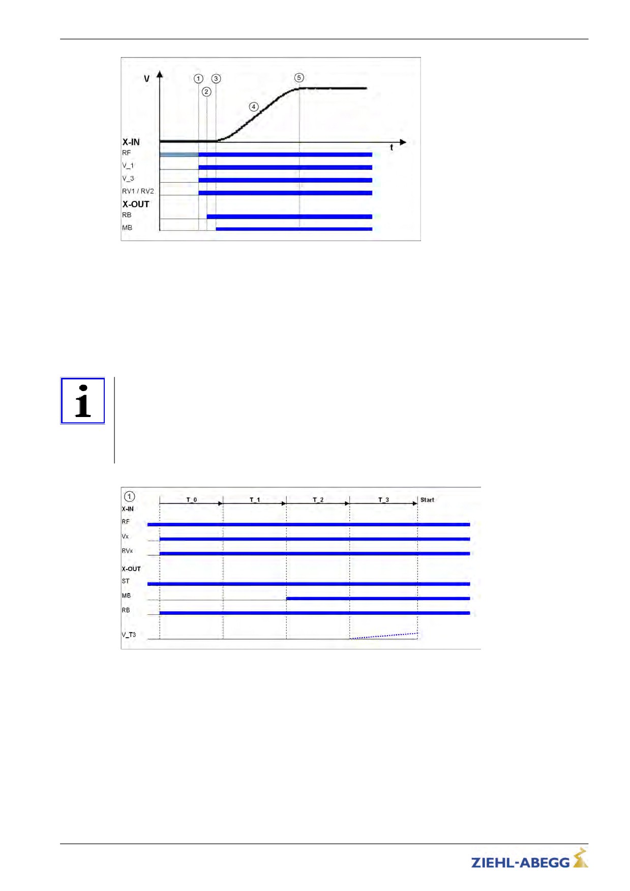
Start-up procedure with acceleration
The elevator control system triggers the following inverter inputs:
• Controller enable (RF), can already be triggered
1
• Speed V_1 and V_3
• Direction of travel RV1
The inverter switches the digital output "MotContact" with a time delay. The motor
2
contactors must be switched without delay with this signal.
The inverter switches the digital output "Mechanical brake MB" time-delayed. The
3
motor brakes must be opened instantaneously with this signal
The controller accelerates the motor up to the highest triggered speed (V_3) according
4
to the set acceleration and round off.
5
Target speed V_3 has been reached.
102/200
Travel options
Start-up and acceleration
RF Controller enable
V_1
Positioning speed
V_3
Travel Speed
RV1 / RV2
Direction default
RB Controller ready
MB_Brake Mechanical brake
11.3
Optimizing start up behavior
Optimizing the start up behavior is only necessary if there is a negative influence on the travel comfort
(e.g. through start up jerks)
Information
• Proper installation condition (rail guides, car suspension, transmission oil filling, etc.)
• The car must be empty and the counterweight completely loaded. Start-up for all loading conditions
can only be optimally adjusted in under these conditions
• The speed control parameters must be correctly set in theController menu (see "Commissioning /
Setting the speed control" chapter)
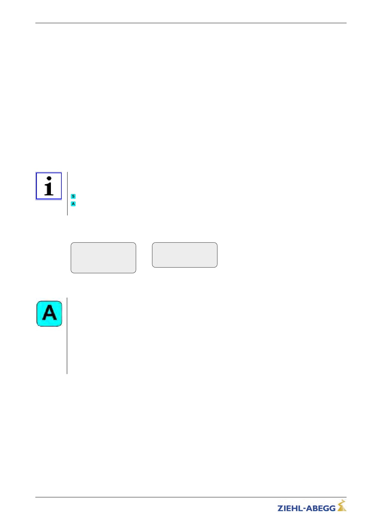
Start-up time sequence
T_0
Time until motor contactors have been opened
T_1
Time until magnetizing flux has been built up (only with asynchronous motors)
T_2
Time until brake has been opened
T_3
Time in which the motor is controlled to speed 0 or accelerated to V_T3
RF Controller enable
Vx Travel speed V_3
RVx Travel direction
ST Controller failure
MB_Brake Mechanical brake
RB Controller ready
The various times can be set in the Start menu
103/200
Travel options
Time optimization through contactor monitoring
With monitoring of contactors activated (Monitors/CO activated) and monitor contacts connected the
time T_0 is optimised. As soon as the contactors are closed, the time T_0 is interrupted and the time
T_1 started.
Time optimization through brake monitoring
If the brake monitoring is activated (Monitoring/BR≠ON) and the monitoring contacts are connected,
the time T_2 is optimized. As soon as the brakes are opened, time T_2 is aborted and time T_3
started.
11.3.1
Damping the start-up jerk
Applies to all start-up variations!
To reduce a startup jolt, you can accelerate to speed V_T3 linearly whilst T_3 is running. This
overcomes the static friction and reduces the startup jolt (see diagram).
11.3.2
Start-up variations
Information
The optimal start-up variations are preset based on the motor type selection in the Motor name plate
menu.
Synchronous motors: MOD5
Asynchronous motors: MOD1
Additional start-up variations are only required in special cases.
The various start-up variations can be configured in the Start/M_Star menu. The speed control
amplification K_START is configured in the Start/K_START menu.
Start-up
Start-up
|-" M_START 1
|-" K_START 1
|-"
3
|-"
3
Start control proce-
Start gain
dure
MOD1 (standard setting for asynchronous motors)
The machine is speed controlled. Up to expiration of T_2, the speed is controlled at target value = 0. A
shaft position change is not corrected. The parameter "K_start" is used to increase the speed control
amplification. It is activated with the start of T_1 and deactivated with the expiration of T_2.
MOD2
Corresponds to the function of MOD1. In addition, the parameter "s_start" is activated. If the position of
the machine changes during time T_2 by the value entered in "s_start", "K_start" is switched off. That
prevents the machine from being damaged due to too high a value of "K_start".
MOD3
The machine is both position and speed controlled. Please note that both controls are set through
"K_start" and are thus dependent on each other. The position and speed control is activated with the
start of T_1 and deactivated with the expiration of T_2.
104/200
Travel options
MOD5 (standard setting for synchronous motors)
The machine is position controlled. The machine position is recorded until expiration of T_2 and is
corrected if it changes. The parameter "K_start" is used to increase the position control amplification. It
is activated with the start of T_1 and deactivated with the expiration of T_2
MOD4
Corresponds to the function of MOD5. In addition, the parameter "s_start" is activated. If the position of
the machine changes during time T_2 by the value entered in "s_start", "K_start" is switched off. That
prevents the machine from being damaged due to too high a value of "K_start".
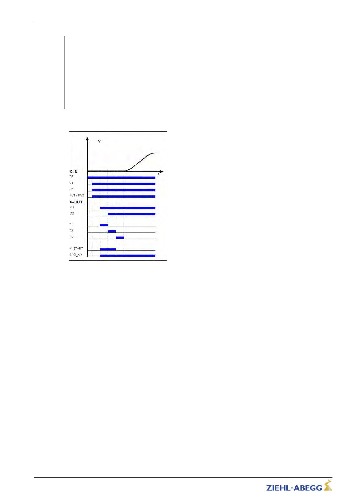
Start-up variations
RF
Controller enable
V_1
Positioning speed
V_3
Travel Speed
RV1 / RV2
Direction default
RB
Controller ready
MB_Brake
Mechanical brake
T_1
Flux build-up time
T_2
Brake opening time
T_3
Speed=0
K_START
MOD1 / MOD2 (Speed control)
MOD3 (position- & speed control)
MOD4 / MOD5 (position control)
SPD_KP Base amplification speed controller
105/200
Travel options
11.4
Optimizing the acceleration
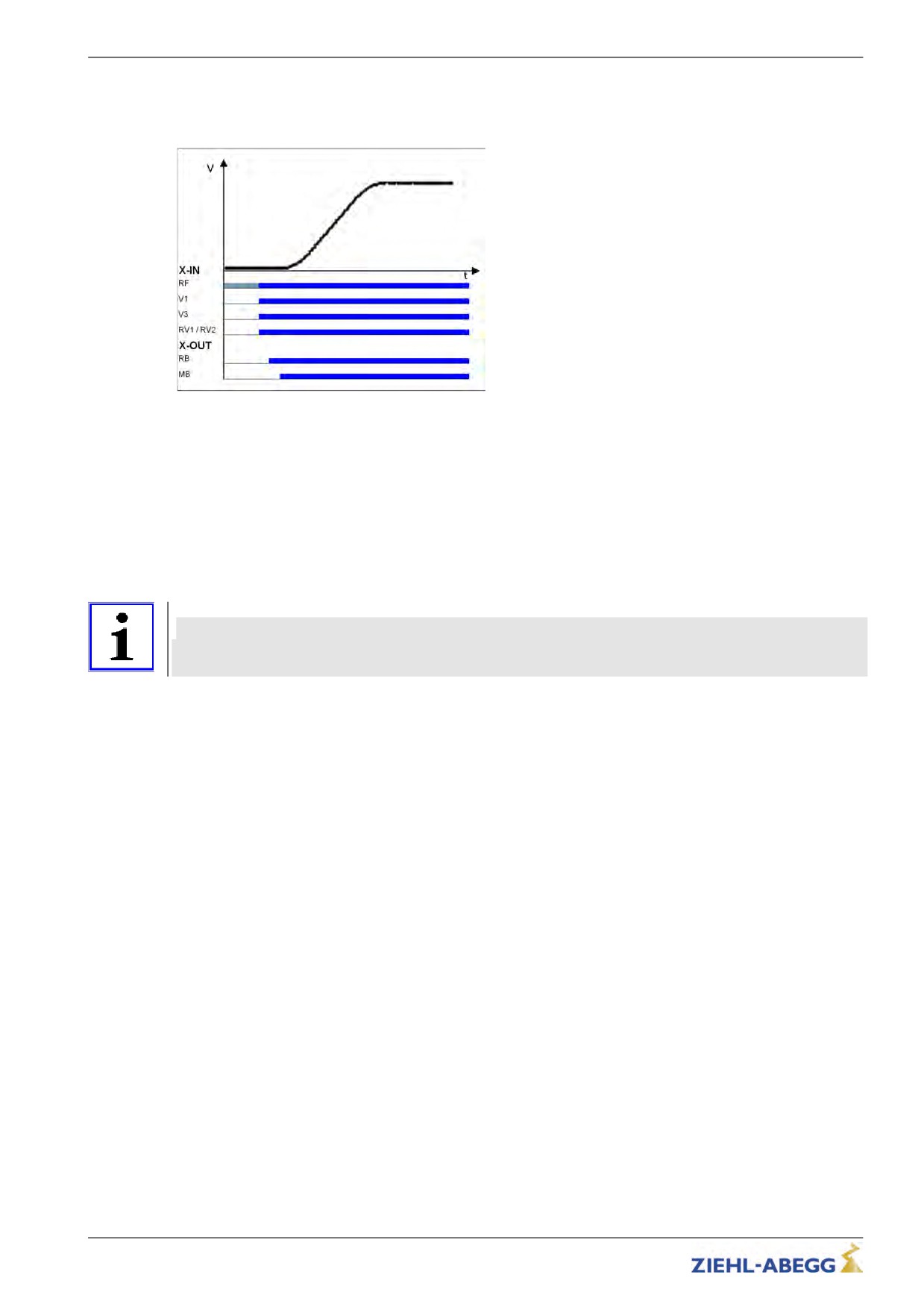
The acceleration torque is defined by the parameter in the Accelerating menu. By changing the
parameter values, you can adapt the curve shape to the requirements
Acceleration ramp
RF Controller enable
V_1
Positioning speed
V_3
Travel Speed
RV1 / RV2
Direction default
RB Controller ready
MB_Brake Mechanical brake
A_POS:
Acceleration preset in m/s². A higher value causes greater acceleration and thus a steeper ramp
R_POS1:
Setting the lower round off A higher value causes a softer round off
R_POS2:
Setting the upper round off. A higher value causes a softer round off.
Information
To achieve optimum starting behavior:
• The motor contactors must be switched instantaneously with the digital output "RB"
• The brakes must be switched instantaneously with the digital output "MB"
106/200
Travel options
11.5
Traveling speed defaults
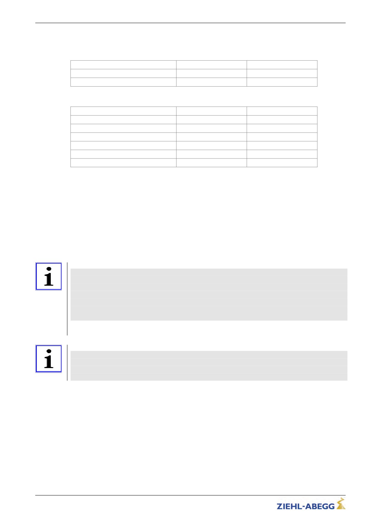
After entering the installation specifications and carrying out the automatic parameter assignment, the
traveling speeds "V_2" and "V_3" are pre-configured in the Travelling menu, dependent on "V*".
Description
Parameter
pre-signment
Intermediate speed V_2
V_2
50% V*
Travel speed V_3
V_3
100% V*
The speeds listed in the table below are permanently preset and thus independent of "V*".
Description
Parameter
pre-signment
Positioning speed
V_1
0,05 m/s
Readjustment speed
V_Z
0,05 m/s
Additional speed V_4
V_4
0,32 m/s
Additional speed V_5
V_5
0,32 m/s
Additional speed V_6
V_6
0,32 m/s
Additional speed V_7
V_7
0,32 m/s
11.6
Distance-dependent deceleration
In a path-dependent deceleration, the deceleration paths are always identical. Independent of the
speed reached at the start of the deceleration.
The path-dependent deceleration can be activated in the menu Decelerating/S_ABH = ON
Path dependent deceleration is carried out during deceleration of:
• V3 R V1
• V2 R V1
• V3 R Drehzahl 0 (only in DCP2/DCP4 protocol)
• V3 R Drehzahl 0 (only in DCP2/DCP4 protocol)
During all other switchovers between two speeds, the deceleration is carried out time-dependent.
Information
Before removing the digital input for the travel speeds V_3 or V_2 the input for the travel speed V_1
must be applied (see diagram "Normal stop at distance-dependent deceleration").
If it is not possible to control two travelling speeds simultaneously for technical reasons (e.g. control of
the speeds by an alternating contact), the distance-dependent delay with the Control system/SIM_-
V1=ON parameter can be activated!
Here it must be noted that the positioning speed V_1 must be activated 100 ms after deactivation of
the travelling speeds V_3 or V_2 at the latest!
If binary speed is specified, there is only a distance-dependent delay at Control system/SIM_V1=ON!
Information
If the signal for the higher traveling speed (e.g. V_3) is switched off for a short time, the inverter
decelerates the motor to positioning speed V_1. For safety reasons, retriggering a higher traveling
speed is ignored. Triggering at a higher traveling speeds is only possible after all the inputs for the
traveling speed have been switched off and the motor has reached the speed 0.
107/200
Travel options
11.6.1
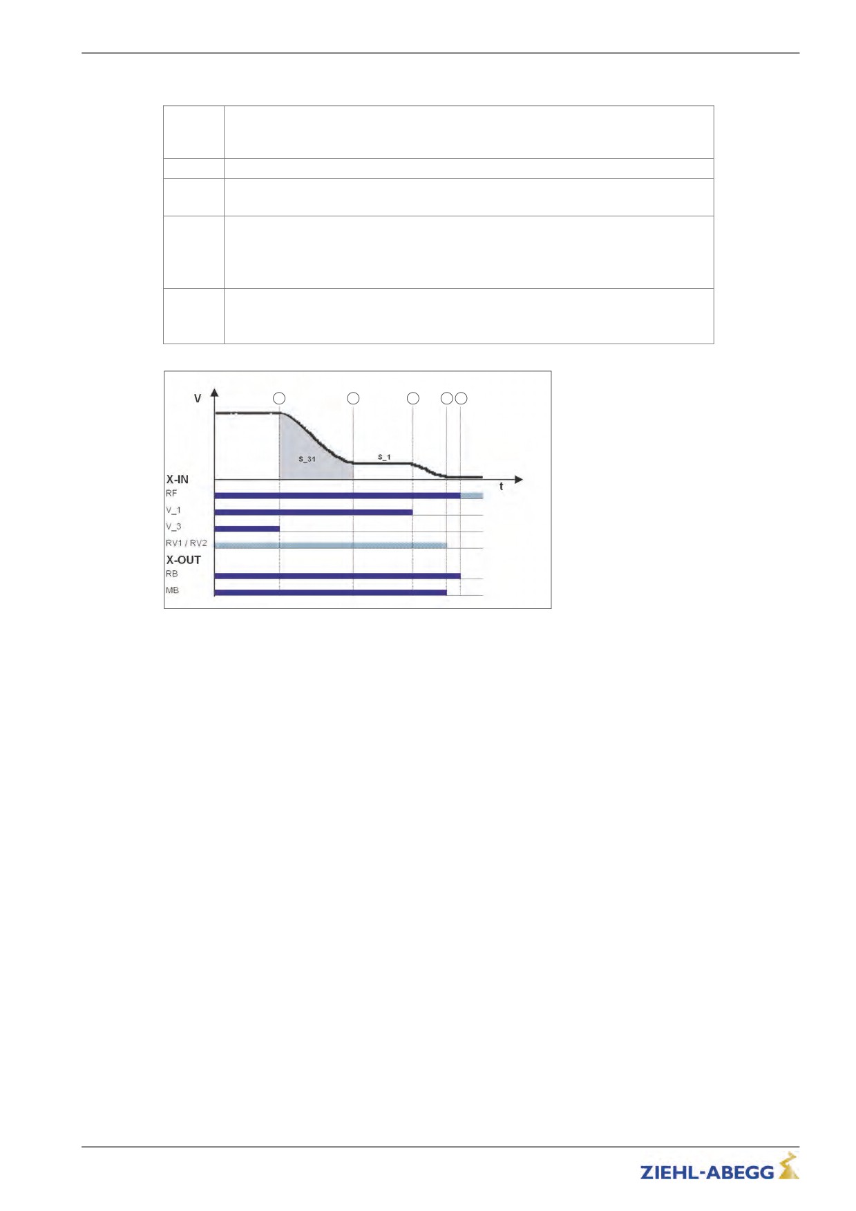
Normal stop during path dependent deceleration
When the switch off point for the traveling speed is reached, the configured final speed
6
V_3 has been reached.
Deceleration is initiated
7
Travel at positioning speed V_1
Positioning speed V_1 is switched off.
8
Motor continues to decelerate.
Speed 0
Output MB is switched off
9
Brake must operate immediately
The motor continues to be fed with current
The current to the motor is switched off
10
Output RB is switched off
Motor contactors must drop immediately
6
7
8
9
10
Normal stop during path dependent deceleration
RF Controller enable
V_1
Positioning speed
V_3
Travel Speed
RV1 / RV2
Direction default
RB Controller ready
MB_Brake Mechanical brake
108/200
Travel options
11.6.2
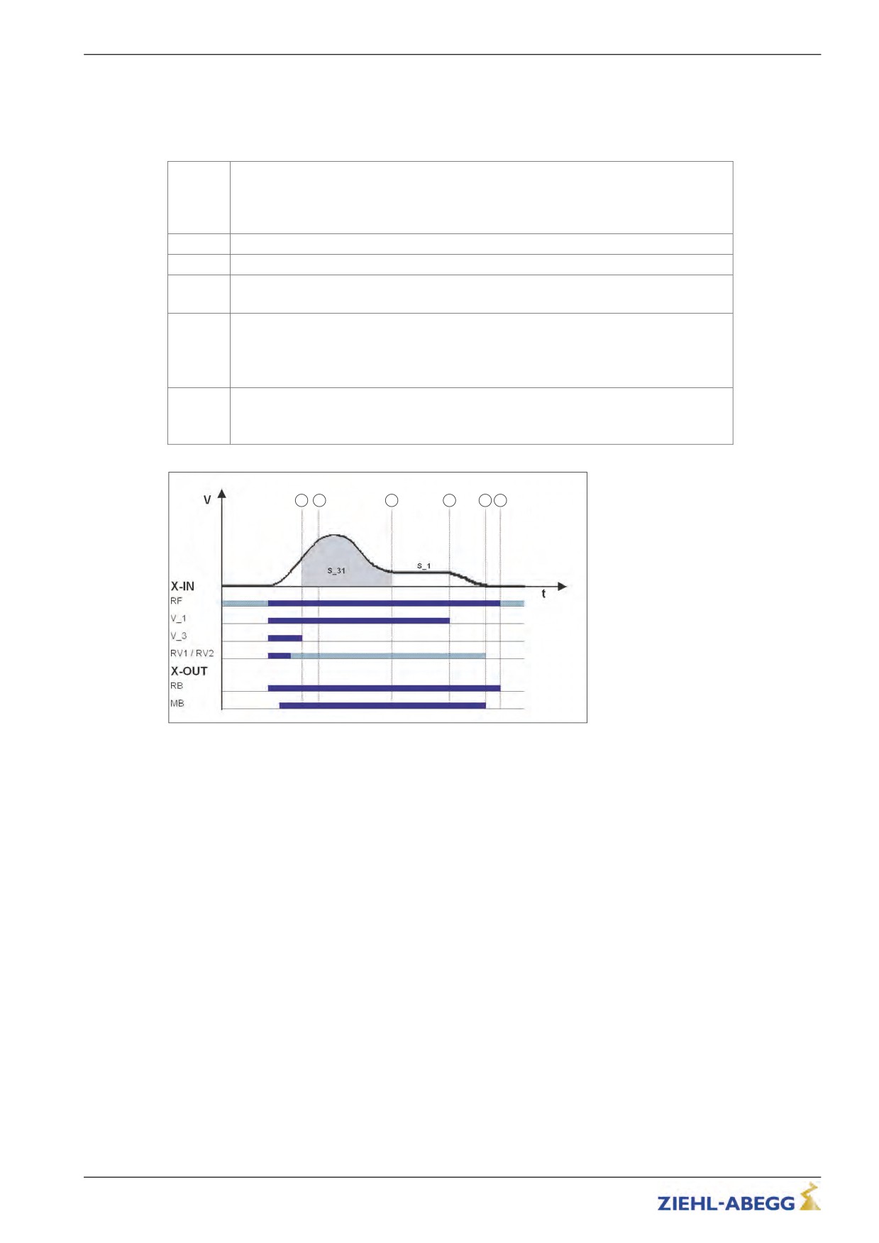
Arch travel with path-dependent deceleration
If the selected final speed (V_2 or V_3) is not reached with short floor clearances, the frequency
inverter carries out arch travel. Independent of the speed reached upon the interrupt time point, the
identical crawl paths are always achieved through the arch travel.
When the switch off point for the traveling speed is reached, the configured final speed
is not yet reached.
6
The motor continues to be accelerated.
The point from which the deceleration must be initiated is calculated.
X
Deceleration is initiated
7
Travel at positioning speed V_1.
Positioning speed V_1 is switched off.
8
Motor continues to decelerate.
Speed 0
Output MB is switched off
9
Brake must operate immediately
The motor continues to be fed with current
The current to the motor is switched off
10
Output RB is switched off
Motor contactors must drop immediately
6
x
7
8
9
10
Arch travel
RF Controller enable
V_1
Positioning speed
V_3
Travel Speed
RV1 / RV2
Direction default
RB Controller ready
MB_Brake Mechanical brake
That means that during a normal trip and during arch travel, the deceleration path V3 R V1 (S_31) and
the crawl path V1 R speed 0 (S_1, only with DCP 1/DCP 3) are identical.
109/200
Travel options
11.7
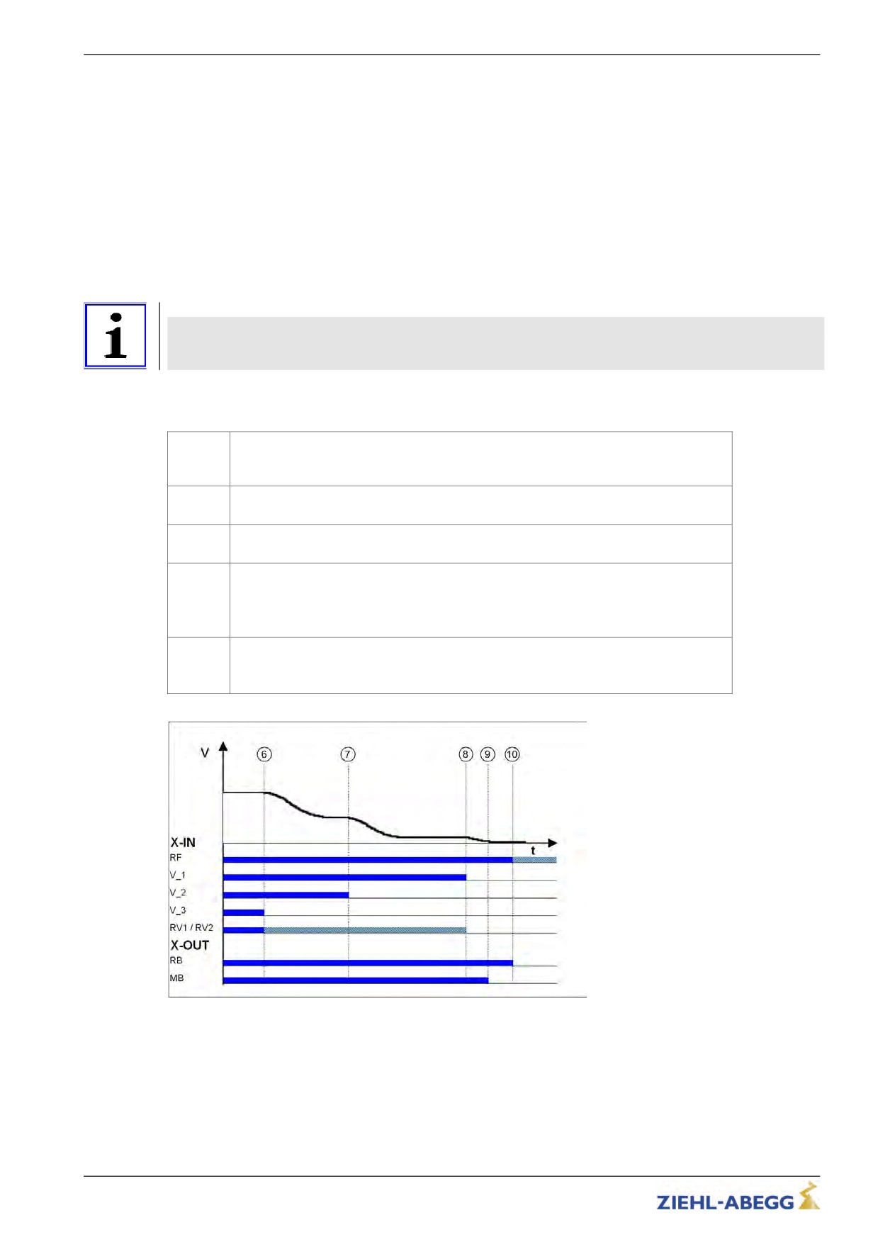
Time-dependent deceleration
Time-dependent deceleration is activated for all speed transitions if the menu Decelerating/S_ABH =
OFF.
With the exception of decelerations of:
• V_3 R V_1
• V_2 R V_1
the decelerations are operated time-dependent. They are independent from the configured function of
the parameter Decelerating / S_ABH
After switching off the current speed preset, the motor is decelerated time-dependent, according to the
configured decelerations and round offs, to the highest speed still triggered.
Information
In a time-dependent deceleration, the deceleration paths vary dependent on the speed attained at the
time the deceleration starts. For this reason, time-dependent deceleration only makes sense if
traveling speed is reached during each trip.
11.7.1
Deceleration with reached traveling speed
When the switch off point for the traveling speed is reached, the configured final speed
6
V_3 has been reached.
Deceleration to V_2 is initiated
Switch off point for V_2
7
Deceleration to V_1 is initiated
Positioning speed V_1 is switched off.
8
Motor continues to decelerate.
Speed 0
Output MB is switched off
9
Brake must operate immediately
The motor continues to be fed with current
The current to the motor is switched off
10
Output RB is switched off
Motor contactors must drop immediately
Time-dependent deceleration with reached traveling speed
RF Controller enable
V_1
Positioning speed
V_2
Intermediate speed
V_3
Travel Speed
RV1 / RV2
Direction default
RB Controller ready
MB_Brake Mechanical brake
110/200
Travel options
11.7.2
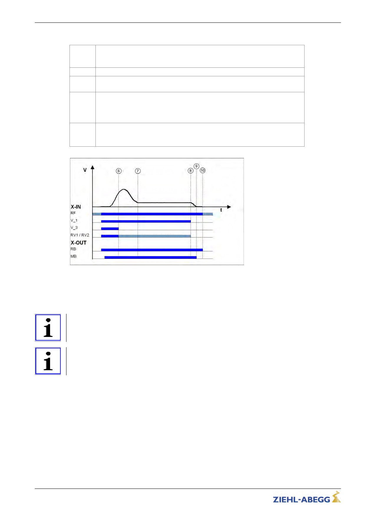
Deceleration when traveling speed has not been reached
When the switch off point for the traveling speed is reached, the configured final speed
6
V_3 is not reached.
Deceleration is initiated
7
Travel at positioning speed V_1
Positioning speed V_1 is switched off.
8
Motor continues to decelerate.
Speed 0
Output MB is switched off
9
Brake must operate immediately
The motor continues to be fed with current
The current to the motor is switched off
10
Output RB is switched off
Motor contactors must drop immediately
Deceleration when traveling speed has not been reached
RF Controller enable
V_1
Positioning speed
V_3
Travel Speed
RV1 / RV2
Direction default
RB Controller ready
MB_Brake Mechanical brake
Information
If the trip duration is monitored by the open loop control, due to the long trip time with a traveling speed
of V_1 an error message may result!
Information
If the traveling speed is switched off just before the preset final speed has been reached, it could
happen that the floor is overshot.
111/200
Travel options
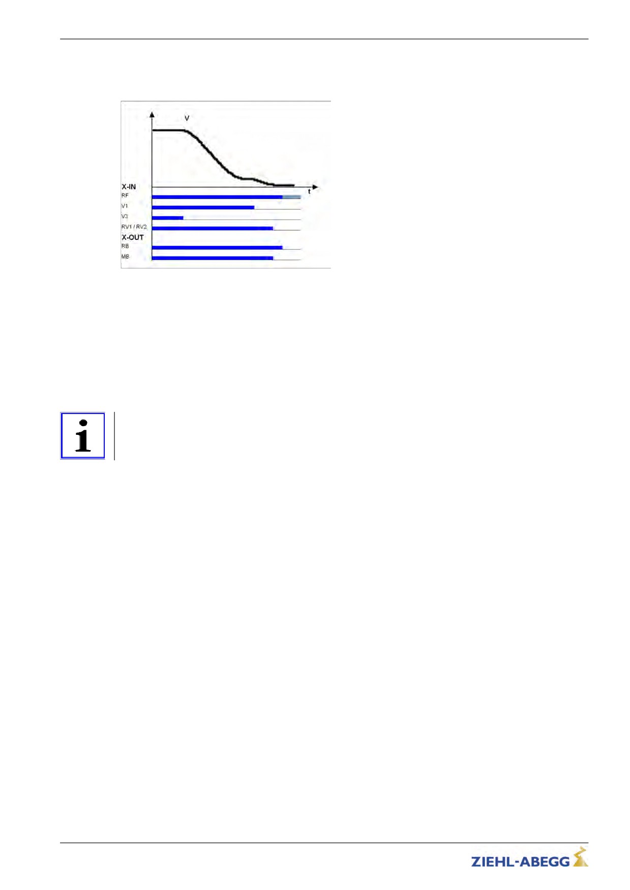
11.8
Optimizing deceleration
The deceleration ramp is defined by the parameter in the Deceleration menu. By changing the
parameter values, you can adapt the curve shape to the requirements
Deceleration ramp
RF Controller enable
V_1
Positioning speed
V_3
Travel Speed
RV1 / RV2
Direction default
RB Controller ready
MB_Brake Mechanical brake
A_NEG: Deceleration preset in m/s². A higher value causes greater deceleration and thus a steeper ramp.
R_NEG1: Setting the upper round off. A higher value causes a softer round off.
R_NEG2: Setting the lower round off A higher value causes a softer round off.
Information
Adapting the parameter modifies the deceleration path V_3 R V_1. The recalculated path is shown in
the display. If necessary, correspondingly adapt the interrupt point for V_3.
112/200
Travel options
11.9
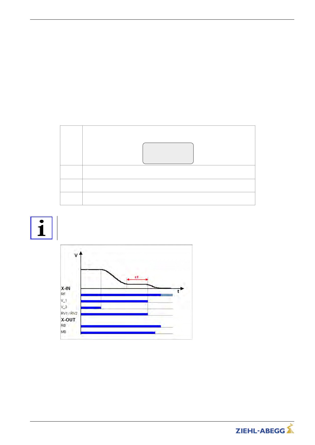
Crawl path optimization
Improvement of:
• Too long creep paths with travelling speed V_1
• non-flush stopping due to V_1 being prematurely switched off
without additional installation work.
Using the crawl path optimization in the menu:
Decelerating / S_DI1
Decelerating / S_DI2
Decelerating / S_DI3
the traveling speeds V_1, V_2 and V_3 are switched off in all floors delayed by the value configured in
the corresponding menu.
Optimizing the crawl paths
Travel to each floor from both directions of travel with the max. traveling speed
1
V_3 or V_2 and check the crawl path s1 in the "INFO / Page 03" menu.
Dist. - - - - - - - - - - - 03
sa: 0.00 s21: 0.52m
sr:^0.00 s31: 1.45m
s1: 0.00 sd: 0.52m
The value for s1 should be the same for all floors from both travel directions.
2
If the crawl paths differ, use the smallest value for s1.
In the Decelerating menu, change the values for "S_DI3" or "S_DI2" to that
3
determined for s1
Check the deceleration behaviour and correct the values for the parameters
4
"S_DI3" or "S_DI2" if necessary.
Information
If s1 has different values, it is not possible to get the same crawl path in all floors!
Deceleration with non-optimized crawl path
RF Controller enable
V_1
Positioning speed
V_3
Travel Speed
RV1 / RV2
Direction default
RB Controller ready
MB_Brake Mechanical brake
113/200
Travel options
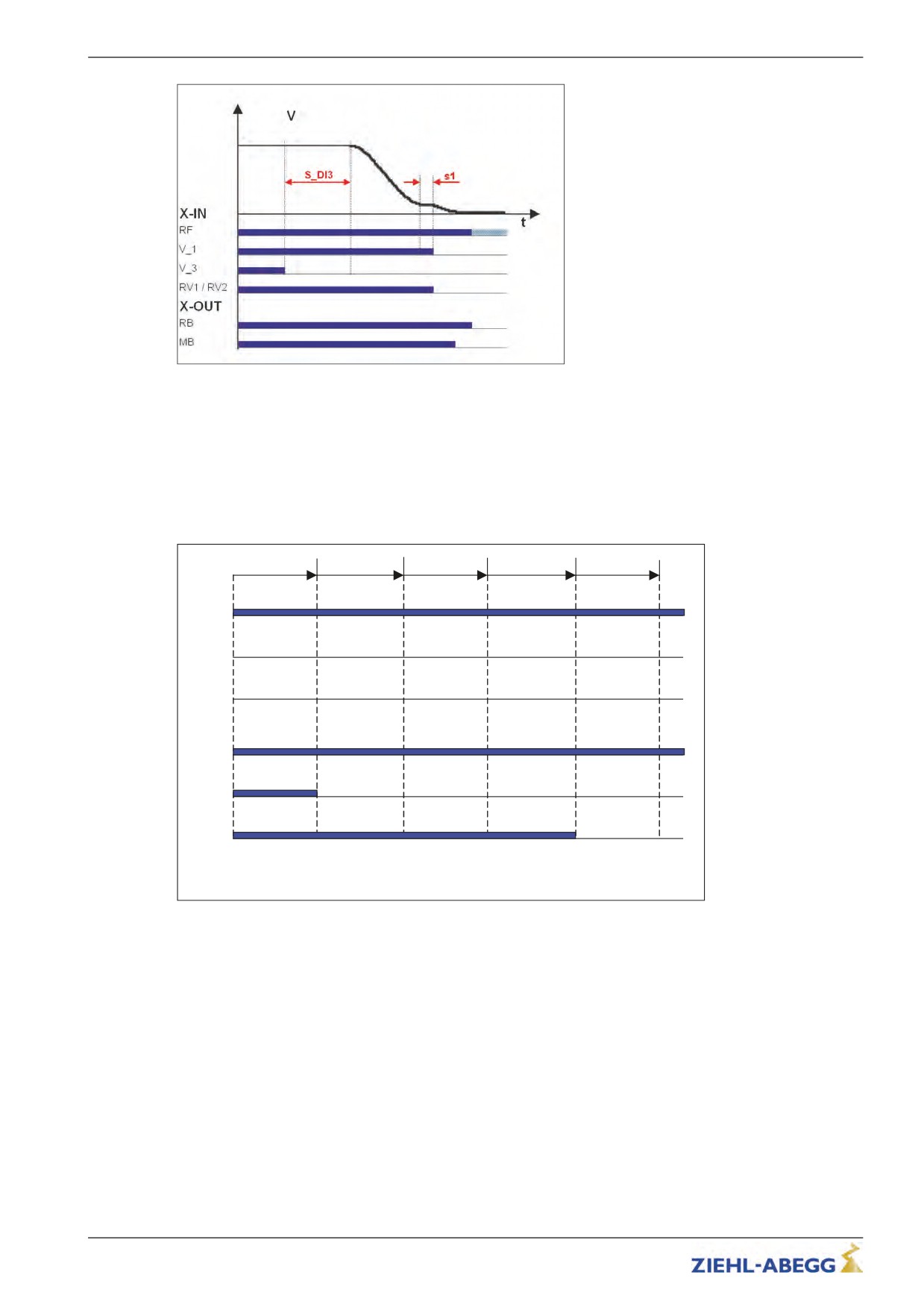
Deceleration with optimized crawl path
RF Controller enable
V_1
Positioning speed
V_3
Travel Speed
RV1 / RV2
Direction default
RB Controller ready
MB_Brake Mechanical brake
11.10
Optimizing stopping
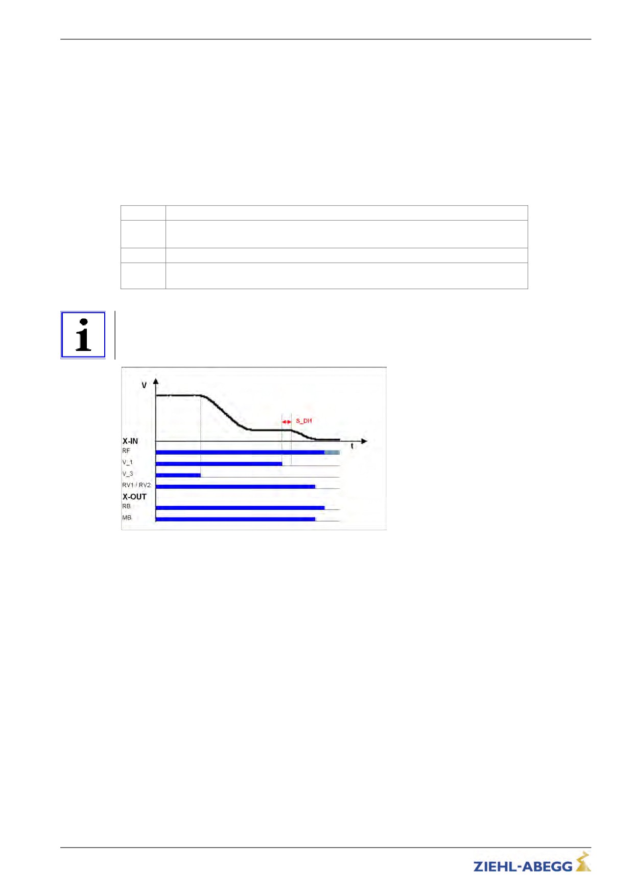
Stopping time sequence
T_4
T_5
T_5a
T_5b
T_6
X-IN
RF
Vx
RVx
X-OUT
St
MB
RB
T_4
Hold speed 0
T_5
Wait until the brake is closed
T_5a additional current feed of the brakes
T_5b Wait until the motor is currentless
T_6
Wait until contactors open
RF Controller enable
Vx Travel speed V_3
RVx Travel direction
ST Controller failure
MB_Brake Mechanical brake
RB Controller ready
The various times can be set in the Stop menu.
114/200
Travel options
Time optimization through brake monitoring
If the brake monitoring is activated (menu Monitoring/BR≠Off) and the monitor contacts are con-
nected, time T_5 is optimized. As soon as the brakes are closed, time T_5 is aborted and time T_5b
started.
Time optimization through contactor monitoring
If the contact monitoring is activated (menu Monitoring/CO=ON) and the monitor contacts are
connected, time T_6 is optimized. As soon as the contactors are open, time T_6 is aborted and the
stopping sequence ends.
11.11
Optimizing the step alignment
1
Ascertain the distance of the flush in each floor by measuring manually
The clearance should be the same in all floors when approaching from both directions.
2
If the values differ, use the smallest value determined.
3
In the Decelerating menu, configure the value for "S_DI1" to the ascertained value.
Check the deceleration behaviour and, if necessary, correct the value for the parame-
4
ter "S_DI1".
Information
If there are different distances to the flush alignments, it is not possible to travel flush to all floors by
modifying the parameter "S_DI1"!
Optimizing the step alignment
RF Controller enable
V_1
Positioning speed
V_3
Travel Speed
RV1 / RV2
Direction default
RB Controller ready
MB_Brake Mechanical brake
115/200
Travel options
11.12
Direct leveling
Information
Direct leveling is only possible when using the DCP2 or DCP4 protocols and an absolute shaft copy
system!
During direct leveling, the control system predetermines the frequency inverter the residual path to be
traveled up to the stopping point.
The inverter slows down the motor in accordance with the specified remaining distance. making it
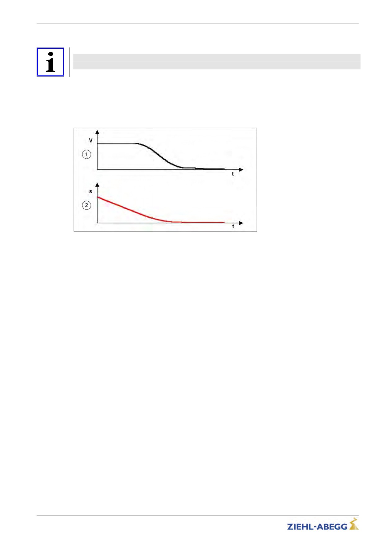
possible to travel to the stop area without a creep path.
Direct leveling with DCP protocol
1
Travel speed V_3
2
Residual distance
116/200
Travel options
11.13
Readjustment
Correction of the rope elongation under load and relieving the load on the car. The rope elongation is
evaluated by the control system.
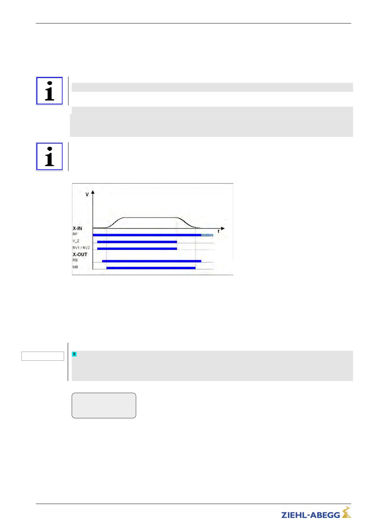
The readjustment speed is configured in the Travelling/V_Z" menu and controlled through a digital
input (configured to V_Z).
Information
The traveling speed for readjustment takes precedence over the other traveling speeds.
To be able to make a readjustment, at least the following input signals need to be present:
• Controller enable
• Readjustment speed V_Z
• Direction default
Information
To prevent oscillation, the control system must wait a suitable amount of time until the rope comes to
rest before the readjustment is activated.
Readjustment speed
RF Controller enable
V_Z Readjustment speed
RB Controller ready
MB_Brake Mechanical brake
11.14
Operation in idle
With the ZETADYN 3 frequency inverter, both synchronous as well as asynchronous motors can be
operated in an idle state.
Caution!
CAUTION!
When operating synchronous motors in idle, strong vibrations and noise development can
result! Therefore, the factor for the speed controller basic-amplification "SPD_KP" must be
reduced to approx. 0.1%.
Controller
|-" SPD_KP
1.00
|-"
0.10
SPD_REG: Base gain-factor
117/200
Travel options
11.15
Fast-start
The motor is energized as the cabin door closes and the mechanical brake is opened. Motor speed is
controlled to 0. This makes it possible to start travel immediately the door is closed.
Information
The Quickstart function may only be used in the door zone range in elevators with adjustment control.
The regulations of DIN EN 81-1 must be observed.
11.15.1
Modulation
Configure digital input in the Control system menu to v=0.
Control
|-" f_I08
v=0
|-"
v=0
Function I08
Standard
DCP
Cabin door closing
Cabin door closing
Actuation of inputs:
Setting the bits by lift control:
• RF - Controller enable
• G2 - RPM 0
• RVx - Default for travel direction
• B1 - travel command
• v=0 - Hold speed 0
• B2 - off switch
• B3 - travelling speed
1
Activation of output:
• B4 - travel direction
• RB - Controller ready
Motor contacts must be switched without a delay.
Setting the bits by frequency converter:
Motor energized
• S1 - travel active
Motor contacts must be switched without a delay.
Motor energized
Activation of output:
Setting the bits by frequency converter:
• MB - mechanical brake
• S6 - mechanical brake
2
Motor brake must be opened without a delay.
Motor brake must be opened without a delay.
Motor speed is controlled to 0.
Motor speed is controlled to 0.
Cabin door is closed
Cabin door is closed
Deactivation of input:
Setting the bits by lift control:
• v=0 - Hold speed 0
• G6 - Intermediate speed or
• G7 - fast speed
Actuation of inputs:
• B3 - travelling speed
3
• V1 - Positioning speed or
Cancelling the bits by lift control:
• V2 - Intermediate speed or
• G2 - RPM 0
• V3 - travel speed
Travel speeds must be actuated no more than 150 ms after input
Travel speeds must be actuated no more than 150 ms
"v=0" has been deactivated!
after input "v=0" has been deactivated!
Caution!
Danger from traveling with cabin door open!
In order to prevent premature starting up in the event of a defective input or fractured wire for
the "Hold speed 0" function, the signals for travel speeds should only be applied after the
"Hold speed 0" function has been switched off!
118/200
Travel options
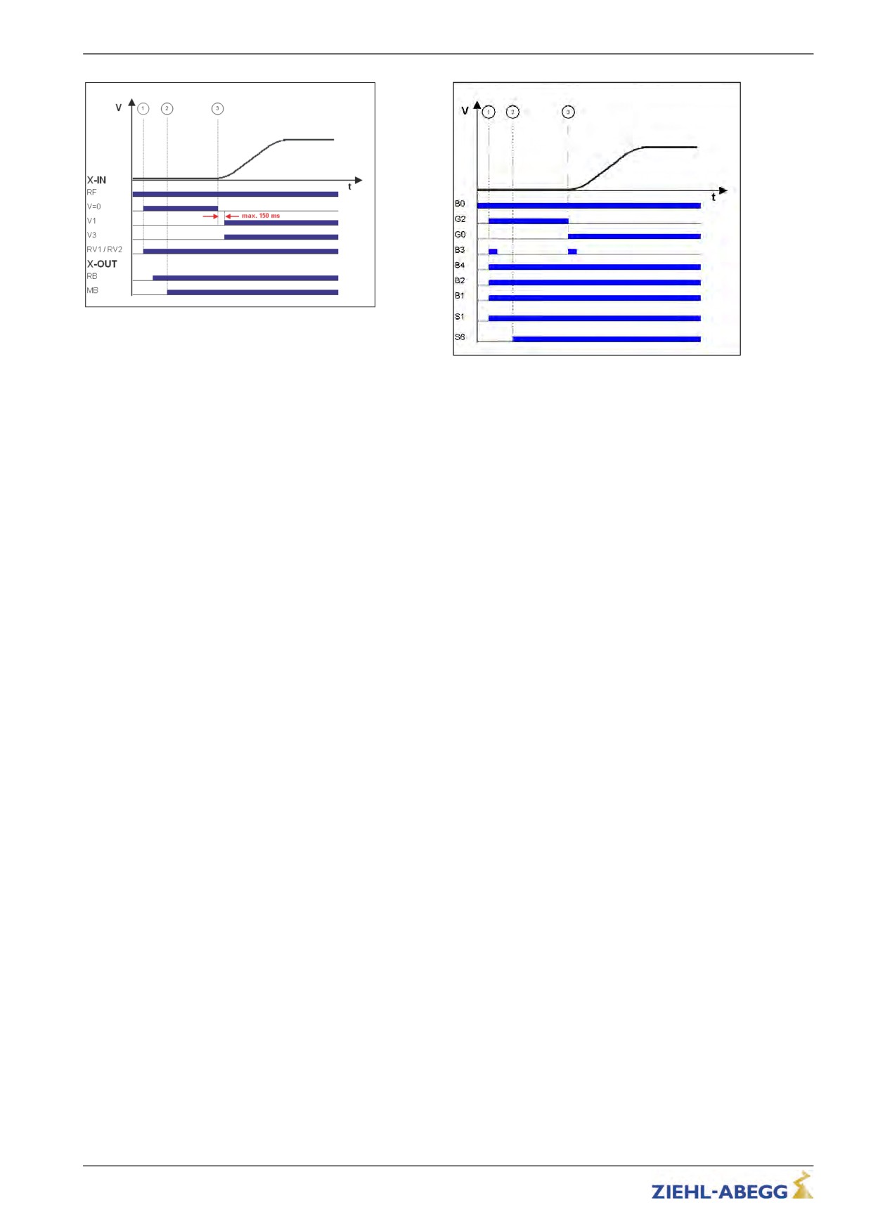
Quickstart with standard actuation
RF Controller enable
v=0
Hold speed 0
V1
Positioning speed
V3
Travel speed V_3
Quick start with DCP actuation
RV1 / RV2
Direction default
B0
Converter enable
RB Controller ready
B1
Travel command
MB_Brake Mechanical brake
B2
Off switch
B3
Travel speed V_3
B4
Direction default
S1
Travel active
S6
Mechanical brake
G2
Speed 0
G7
Travel speed
11.15.2
Monitoring functions for Quickstart
• If the drive is maintained at speed 0 for longer than 20 s, the inverter goes to fault mode, displaying
ERR780/Quickst. t-limit
• If the input signal "Drehzahl 0 halten" is set during travel, the inverter goes to fault mode, displaying
ERR781 / Quick. bei Fahrt
• If the motor moves by more than ± 7 mm with the input set to speed 0, the frequency inverter goes
to fault mode, displaying ERR529 / Quickstart Alarm
• The monitoring time for the rotary encoder (T_GUE) is started after the function "Speed 0" has
been switched off
119/200