ZETADYN 3BF. Operating instruction (Part.-No. 00163264-GB 2/200) - page 1
Frequency inverter
Store for future use!
Art.-Nr. 00163264-GB
Content
1
General information
8
1.1
Validity
8
1.2
Structure of the operating instructions
8
1.3
Target group
8
1.4
Structure of operating instructions
8
1.5
Exclusion of liability
8
1.6
Copyright
9
2
Safety instructions
9
2.1
General
9
2.2
Intended use
9
2.3
Pictographs
9
2.4
Product safety
10
2.5
Requirements placed on the personnel / due diligence
10
2.6
Commissioning
10
2.7
Working on device/hazards through residual voltage
10
2.8
Modifications / interventions in the device
10
2.9
Operator’s obligation of diligence
11
2.10
Employment of external personnel
11
3
Product overview
12
3.1
Application
12
3.2
Functional description
12
3.3
Rating plate
12
3.4
Transport
12
3.4.1
Storage duration:
13
3.5
Disposal & recycling
13
4
Mechanical installation
13
4.1
General notes
13
4.1.1
Wall installation
13
4.1.2
Switch cabinet installation
13
4.2
Dimensions
14
5
Electrical installation
16
5.1
EMC-compatible installation
17
5.1.1
EMC-compatible assembly of the control cabinet
18
5.2
Device set-up / Position of connection terminals
19
5.2.1
ZETADYN 3C011 to 3C074
19
5.2.2
ZETADYN 3BF110 to 3BF180
20
5.3
Protective ground connection
21
5.4
Mains connection
(X1)
21
5.4.1
Network form
21
5.4.2
Cable cross section
21
5.4.3
Mains fuse
21
5.4.4
Type of cable
21
5.4.5
Connection
21
5.5
Line reactor-radio interference filter
22
5.6
Residual current operated device (RCCB)
23
5.7
Control transformer in the mains feed line
23
5.8
Motor connection
(X1)
24
5.8.1
Cable cross section
24
5.8.2
Type of cable
24
5.8.3
Cable length
24
5.8.4
Connection
24
2/200
5.8.5
Motor contactors
24
5.8.6
Contacting the shielding in the switch cabinet
25
5.8.7
Contacting the shielding on the motor
25
5.9
Motor temperature monitoring (X-MT)
26
5.10
Brake-Resistor (X1)
26
5.11
Digital inputs (X-IN)
28
5.11.1
Connection with external power supply
28
5.11.2
Connection with internal power supply
28
5.11.3
Technical data
29
5.11.4
Terminal assignment X-IN
29
5.11.5
Binary traveling speed default
30
5.12
Digital outputs (X-OUT)
30
5.12.1
Digital outputs X-OUT
30
5.12.1.1
Connection X-OUT
30
5.12.2
Digital output X-BC:PWM
30
5.12.2.1
Connection PWM
31
5.12.3
Technical data
31
5.12.4
Terminal assignment X-OUT
31
5.13
DCP / CAN interface (X-DCP, X-CAN)
32
5.13.1
DCP
32
5.13.2
CANopenLift
32
5.14
Encoder connection asynchronous motors (X-ENC8 X-ENC15)
33
5.14.1
Technical data X-ENC8, X-ENC9 and X-ENC15
33
5.14.2
Terminal assignment X-ENC8
33
5.14.3
Pin assignment X-ENC9 / X-ENC15
34
5.14.4
Encoder connection to terminal X-ENC8
34
5.15
Encoder connection synchronous motors (X-ENC15)
35
5.15.1
Technical data X-ENC15
35
5.15.2
Pin assignment X-ENC15 for absolute value encoder with EnDat/SSI interface
35
5.15.3
Pin assignment X-ENC15 for absolute value encoder type ERN1387 (not for ZETADYN
3C-MRL)
36
5.16
Artificial encoder (X-ENCO)
36
5.16.1
Technical data X-ENCO
36
5.16.2
Connection X-ENCO
37
5.17
External 24V power supply (X-EXT)
37
5.17.1
Technical data
37
5.17.2
Connection X-EXT
37
5.18
Monitoring the motor contactors(X-CO)
38
5.18.1
Technical data
38
5.18.2
Connection
38
5.19
Brakes
39
5.19.1
Brake release monitoring (X-BR)
39
5.19.2
Connection X-BR
39
5.19.3
Triggering of the brakes
40
5.20
Connection suggestion ZETADYN 3BF (asynchronous motor)
41
5.21
Connection suggestion ZETADYN 3BF (synchronous motor)
42
6
Accessories
43
6.1
Line reactor-radio interference filter
43
6.1.1
Technical data line reactor and radio interference filter
43
6.1.2
Mechanical installation
44
6.1.3
Dimensions
45
6.1.4
Allocation of the line reactor-radio interference filter to the frequency inverter
46
6.2
Operating terminal ZETAPAD
47
6.2.1
Mounting / Fastening
47
6.2.2
Dimensions
47
6.2.3
Connection
47
3/200
7
Operation and parameterising
48
7.1
Possibilities for operation and configuration
48
7.1.1
Operating terminal ZETAPAD
48
7.1.2
Remote control via ZETAMON software
48
7.1.3
Remote control via the elevator controller display
48
7.2
Menu navigation
48
7.2.1
Control key functions
49
7.2.2
Menu and parameter navigation
49
7.2.3
The different operating levels
49
7.2.4
Meaning of the arrows appearing in the display:
50
7.3
Entering numerical values
50
7.3.1
Continuous change of a parameter value
50
7.3.2
Changing individual digits
50
8
Start-up
51
8.1
Preconfigured inverter
51
8.2
Switching on the frequency inverter
52
8.3
Parameterization of the frequency inverter
52
8.4
Automatic operating-curves default
55
8.5
Setting the switch-off points
56
8.5.1
Cut-off points for travel speed V_3
56
8.5.2
Cut-off points for travel speed V_2
56
8.5.3
Cut-off points for travel speed V_1
57
8.6
Carrying out the first test run
57
8.7
Optimisation of the startup and drive behaviour
57
9
Serial communication
59
9.1
DCP (Drive Control & Position)
59
9.1.1
Electrical connection
59
9.1.2
The various DCP protocols
59
9.1.3
Configuring in DCP mode
61
9.1.3.1
Activating the DCP interface
61
9.1.3.2
Setting the DCP-leveling behavior
61
9.2
CANopenLift
62
9.2.1
Start-up the CAN-interface
62
9.2.1.1
Information for start-up
62
9.2.1.2
Frequency inverter
62
9.2.1.3
Bus-cable
62
9.2.1.4
Wiring
62
9.2.1.5
Electrical connection
63
9.2.1.6
Activating the interface
63
9.2.1.7
Operation modes
63
9.2.1.8
Command- and Statusbits of the recorder
64
9.2.2
Parameter
65
9.2.2.1
Parameter settings
65
9.2.2.2
Network Management Status
65
10
Parameter list
66
10.1
Basic-Level
66
10.1.1
Startup menu
66
10.2
Advanced-Level
70
10.2.1
LCD & Password menu
70
10.3
Motor name plate menu
71
10.4
Encoder & BC menu
72
10.5
Installation menu
73
10.6
Control system menu
74
10.7
Monitoring menu
79
10.8
Start menu
81
4/200
10.9
Acceleration menu
82
10.10 Travel menu
83
10.11 Decelerating menu
83
10.12 Stop menu
84
10.13 Controller menu
85
10.14 Parameter set 2 menu
86
10.15 Statistic menu
87
10.16 Memory Card menu
88
10.17 MMC-Recorder menue
89
10.18 Encoder adjustment menu
90
10.19 Safety gear menu
91
10.20 HW-Ident. menu
91
10.21 Power section menu
92
10.22 Menu checks
92
10.23 CAN menu
92
10.24 ZA-Intern menu
93
10.25 INFO menu
94
11
Travel options
102
11.1
Normal travel
102
11.2
Start-up and acceleration
102
11.3
Optimizing start up behavior
103
11.3.1
Damping the start-up jerk
104
11.3.2
Start-up variations
104
11.4
Optimizing the acceleration
106
11.5
Traveling speed defaults
107
11.6
Distance-dependent deceleration
107
11.6.1
Normal stop during path dependent deceleration
108
11.6.2
Arch travel with path-dependent deceleration
109
11.7
Time-dependent deceleration
110
11.7.1
Deceleration with reached traveling speed
110
11.7.2
Deceleration when traveling speed has not been reached
111
11.8
Optimizing deceleration
112
11.9
Crawl path optimization
113
11.10 Optimizing stopping
114
11.11 Optimizing the step alignment
115
11.12 Direct leveling
116
11.13 Readjustment
117
11.14 Operation in idle
117
11.15 Fast-start
118
11.15.1 Modulation
118
11.15.2 Monitoring functions for Quickstart
119
12
Emergency evacuation
120
12.1
Evacuation with 1-phase mains supply 230V AC
120
12.1.1
Parameterisation
121
12.2
Evacuation with UPS
122
12.2.1
Evacuation through UPS with optimum power
122
12.2.2
Evacuation through UPS with minimum power
123
12.2.3
Parameterisation
123
12.3
Improving the positioning
125
12.3.1
Parameterisation
125
12.4
Connection diagram for UPS to ZETADYN 3
126
12.5
Emergency evacuation by opening the brakes
127
12.5.1
Monitor function
127
5/200
13
Error diagnosis
128
13.1
Travel abort and acknowledgement during malfunctions
128
13.1.1
Travel abort
128
13.1.2
Acknowledgement
128
13.2
Light emitting diodes
128
13.2.1
Software update
129
13.3
Readout the error memory
129
13.4
Delete error memory
130
13.5
Error list
131
13.5.1
Masc-Funktion
131
13.5.2
Block function
131
13.5.3
Notes 0xx
131
13.5.4
Error 1xx
132
13.5.5
Error 2xx
132
13.5.6
Error 3xx
134
13.5.7
Error 4xx
136
13.5.8
Error 5xx
138
13.5.9
Error 7xx
141
13.5.10 Error 8xx
142
13.5.11 Error 9xx
143
13.5.12 Information texts
144
13.6
Operating conditions of the inverter
145
13.7
Frequent startup problems
146
13.8
Automatic parameter check (APC)
146
13.9
Automatic parameter diagnostics (APD)
146
14
Energy saving
147
14.1
Stand-by function frequency converter
147
14.1.1
Standby 1
147
14.1.1.1
Activation of stand-by 1 mode
147
14.1.2
Standby 2
147
14.1.2.1
Activation of stand-by 2 mode
147
14.2
Power Feedback Unit (PFU)
148
14.2.1
Stand-by operation of the power feedback unit
148
14.2.1.1
Activation of stand-by mode
148
14.2.1.2
Electrical connection stand-by mode
149
14.2.1.3
Power feedback unit in connection with automatic emergency evacuation.
149
15
Special functions
151
15.1
Changing the Clock frequency
151
15.1.1
Fixed presetting of the clock frequency (Menu Power sectionl/M_PWM=Fix f_PWM)
151
15.1.2
Automatic adjustment if the clock frequency (Menu Power sectionl/M_PWM=Auto)
151
15.2
Encoder offset-alignment
151
15.2.1
Load-free alignment SSI-Encoder
152
15.2.2
Load-free alignment EnDat-Encoder
155
15.2.3
Checking the load-free alignment of the SSI- & EnDat-encoders
156
15.2.4
Rotary encoder calibration with closed brake
158
15.2.5
Alignment absolute encoder type ERN1387
160
15.2.6
Error messages during encoder offset alignment
161
15.3
Safety Brake
162
15.4
Reset
164
15.5
Memory card
165
15.5.1
Software update
165
15.5.1.1
Software update with the ZApad operating terminal
165
15.5.1.2
Software update without the ZETAPAD operating terminal
166
15.5.1.3
Error flash code during a software update
167
15.5.2
Saving parameters
167
15.5.3
Loading parameters
168
6/200
15.5.4
Saving parameters lists, printer lists and error lists
168
15.5.5
Performing measurements
169
15.5.6
Saving configurations
169
15.5.7
Loading configurations
170
15.6
Checking the motor phases
171
15.7
Field weakening
171
15.8
Encoder-less operation (Open-Loop)
172
15.8.1
Activate operating mode for operation without encoder
172
15.8.2
Parameter for Open-Loop-operation
173
15.8.3
Functions with Open-Loop-operation
174
15.8.3.1
U/f-characteristic curve
174
15.8.3.2
Current-control
174
15.8.3.3
Slip-compensation
174
15.8.3.4
Tilting protection
176
15.8.4
Improvements with Open-Loop-operation
176
15.8.4.1
Optimizing start up behavior
176
15.8.4.2
Slip-compensation
176
15.9
Operation with a 3-phase 230 VAC power supply
177
15.10
Controlled emergency stop in inclined elevators
178
15.11
Travel direction counter
179
15.11.1 Parameters for the travel direction counter
179
15.11.2 Parametrization of the counter
179
15.11.3 Output functions
180
15.11.4 Resetting the travel direction counter
180
15.12
Self-monitoring of the brakes according to EN81-A3
180
15.12.1 Activation of the self-monitoring
180
15.12.2 Activation of the ZETADYN lock in case of a malfunctioning brake circuit
181
15.12.3 Function test of the self-monitoring
181
16
Enclosure
182
16.1
Technical data ZETADYN 3BF
182
16.1.1
ZETADYN 3BF011 - 032
182
16.1.2
ZETADYN 3BF040 - 074
183
16.1.3
ZETADYN 3BF110 - 180
184
16.2
EU declaration of conformity
185
16.3
Adjustment card
187
16.4
Allocation brake resistance, line reactor and radio interference filter
188
16.5
Type designation
189
16.6
Part no
190
16.7
Certificates
191
16.8
Index
197
7/200
General information
1
General information
1.1
Validity
This instruction manual applies to:
Frequency inverter from the series:ZETADYN 3BF
the most current software version taken into account: 3.50
1.2
Structure of the operating instructions
These operating instructions help you to work safely on and with the frequency inverter ZETADYN
3BF. They contain safety instructions that must be complied with as well as information that is required
for failure-free operation of the frequency inverter.
The operating instructions are to be stored together with the frequency inverter. It must be ensured
that all persons who have to perform activities on the frequency inverter can consult the operating
instructions at any time. Instructions for use in accordance with the German Occupational Safety and
Health Act and the German Work Equipment Ordinance must be provided in addition to the operating
instructions.
Keep the operating instructions for continued use. They must be passed-on to all successive owners,
users and final customers.
1.3
Target group
The operating instructions address persons entrusted with planning, installation, commissioning and
maintenance and servicing and who have the corresponding qualifications and skills for their job.
1.4
Structure of operating instructions
The operating manual has a systematic structure. The order of the individual chapters corredsponds
to the order of the work steps for first time installation of the device.
The operating instructions contain the following information:
• Device description
• Mechanical and electrical installation
• Accessories
• Operation and parameterising
• Start-up
• Parameter list
• Drive options and special functions
• Evacuation mode
• Diagnostic
• Software ZETAMON
• Enclosure
1.5
Exclusion of liability
It has been established that the content of these operating instructions is concurrent with the
frequency inverter hardware and software described.
It is still possible that non-compliances exist; no guarantee is assumed for complete conformity. The
contents of this manual are put through periodic reviews. Necessary modifications are incorporated
into the next version.
ZIEHL-ABEGG SEis not liable for damage due to misuse, incorrect use, improper use or as a
consequence of unauthorized repairs or modifications.
Symbols description
Asynchronous motors
The contents in the operating instructions refer specifically to the operation of asynchronous motors.
8/200
Safety instructions
Synchronous motors.
The contents in the operating instructions refer specifically to the operation of synchronous motors.
1.6
Copyright
These operating instructions contain copyright protected information. The operating instructions may
be neither completely nor partially photocopied, reproduced, translated or put on data medium without
previous explicit consent from ZIEHL-ABEGG SE. Infringements are liable for damages.
All rights reserved, including those that arise through patent issue or registration on a utility model.
2
Safety instructions
2.1
General
This chapter contains instructions to prevent personal injury and property damage.
These instructions do not lay claim to completeness. In case of questions and problems, please
consult our company technicians.
2.2
Intended use
The ZETADYN 3BF is a frequency inverter for RPM control of three-phase current motors. The device
is not designed for any other use than those listed here - this is considered as improper use.
Reading these operating instructions and complying with all contained instructions - especially the
safety instructions contained therein - are considered part of intended use. Furthermore, carrying out
all inspection work in the prescribed scheduled intervals is part of intended use
The operator of the ZAdyn4C is liable for any personal harm or material damage arising from non-
intended use! The manufacturer shall bear no liability for such damages.
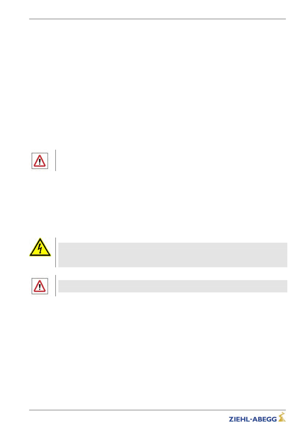
2.3
Pictographs
Safety instructions are highlighted with warning triangles and are depicted according to the degree of
hazard as follows.
Danger!
General hazardous area. Death or severe injury or significant property damage can occur if the
corresponding precautions are not taken!
Warning!
Risk of moderate or minor injury if the corresponding precautions are not taken!
Caution!
Material damage is possible if the corresponding precautions are not taken!
CAUTION!
Danger!
Danger by dangerous, electric voltage! Death or severe injury can occur if the corresponding
precautions are not taken!
Information
Important information and advice for user
9/200
Safety instructions
2.4
Product safety
The device conforms to the state of the art at the time of delivery and is fundamentally considered to
be reliable. The device and its accessories must only be used in a flawless condition and installed and
operated with compliance to the operating instructions.
Exceeding the limits stated in the “Enclosure / technical data” chapter can lead to a defect in the
device.
2.5
Requirements placed on the personnel / due diligence
Persons entrusted with the planning, installation, commissioning and maintenance and servicing in
connection with the device must have the corresponding qualifications and skills for these jobs. Based
on their training, knowledge and experience as well as knowledge of the relevant standards, they
must be able to judge the work transferred to them and be able to recognize possible hazards.
In addition, they must be knowledgeable about the safety regulations, EU directives, rules for the
prevention of accidents and the corresponding national as well as regional and in-house regulations.
Personnel to be trained or instructed and apprentices are only permitted to work on the device under
the supervision of an experienced person. This also applies to personnel undergoing general training.
Comply with the legal minimum age
2.6
Commissioning
Danger!
During commissioning, unexpected and hazardous conditions can arise in the entire installation due to
defective adjustments, defective components or incorrect electrical connections
During the commissioning following has to be observed:
• Remove all persons and objects from the hazardous area
• The EMERGENCY-STOP functions must be in working order
• The mechanical safety brakes must be installed and in working order
• Commissioning is only permitted with compliance to the EMC directive 39/336/EEC
2.7
Working on device/hazards through residual voltage
Before working on previously installed devices, separate them from the mains and secure them
against reconnection.
Danger!
Through use of capacitors, danger of death exists even after switching off the device through directly
touching the energized parts or due to parts that have become energized due to faults.
Wait at least 3 minutes before working on the device.
The safe isolation from the supply must be checked using a two-pole voltage detector.
Danger!
It is generally forbidden to carry out work on electrical live parts. Protection class of the device when
open is IP 00! It is possible to touch hazardous voltages directly!
2.8
Modifications / interventions in the device
For reasons of safety, no unauthorized interventions or modifications may be made on the device .
All planned modifications must be authorized by the manufacturer in writing.
Use only genuine spare parts / genuine wearing parts / genuine accessories from the ZIEHL-ABEGG
SE.These parts were specifically designed for the device. There is no guarantee that parts from non-
original sources are designed and manufactured in correspondence with load and safety require-
ments.
Parts and special equipment not supplied by the ZIEHL-ABEGG SE are not approved for use.
10/200
Safety instructions
2.9
Operator’s obligation of diligence
The device has been designed and constructed with consideration of a hazard analysis and after
carefully selecting the harmonized standards to be complied with as well as additional technical
specifications. It thus complies with the state-of-the art and ensures the highest degree of safety.
However, this safety can only be implemented in operational practice if all measures necessary for
this purpose are taken. The operator of the installation has the obligation of due diligence to plan
these measures and monitor their implementation.
In particular, the operator must ensure that
• The device is only used as intended (cmp. chapter "Product overview" concerning this)
• The installation is operated solely in a flawless, functional condition and that especially the safety
devices are periodically checked for their properly functioning condition
• The required personal safety gear is available to and used by the operating, maintenance and
repair personnel
• The operating instructions are always readily available at the location where the frequency inverter
is being used, are complete and are in legible condition
• Only sufficiently qualified and authorized personnel operate, maintain and repair the device
• these staff receive regular instruction in all relevant occupational safety and environmental protec-
tion issues, are knowledgeable about the operating instructions and, especially, are familiar with the
safety instructions contained therein.
• All safety and warning notices attached to the device are never removed and remain legible
2.10
Employment of external personnel
Maintenance and service work are frequently carried out by external employees who often do not
recognize the specific situations and the thus resulting dangers.
These persons must be comprehensively informed about the hazards in their area of activity.
You must monitor their working methods in order to intervene in good time if necessary.
11/200
Product overview
3
Product overview
3.1
Application
The ZETADYN 3BF is a field-oriented Frequency inverter for speed control of three-phase motors
developed for use in elevator machines.
The inverter is equipped with a microprocessing control. This drives the motor based on time and
travel-dependent programs, which can be selected through the upstream elevator controls. The use of
IGBT modules and a pulse width modulation in which the clock frequencies can be modified enable
low-noise motor operation. The user interface specifically matched to elevator technology, interfaces
and software enable simple installation and commissioning of the device.
The Frequency inverter is designed for elevator installations for passenger and freight transport with a
high demand on travel comfort and positioning accuracy.
Frequency inverter for operating asynchronous motors and synchronous motors are available.
3.2
Functional description
The Frequency inverter places a three-phase line with variable frequency and variable voltage at your
disposal. The amount of voltage and rate of frequency depends on the selected traveling speed and
the load to be carried. By using a field-orientated control, the motor is optimally operated at all
operating points. As a result, every torque required is made available practically without delay. Even in
standstill (speed 0), the motor’s entire torque rating is available.
Control
All operating curves are run speed controlled and load independent. The flux control enables very
precise compliance with the specified operating curves throughout the entire speed-control range.
The closed loop control can be used up to a speed of 3.2 m/s (higher speeds available on request).
The brakes operate almost wear-free throughout the controlled operation from speed 0 (start) to
speed 0 (stop).
centrifugal masses
In order to reduce the acceleration current, all additional centrifugal masses are to be removed. Solid
hand wheels are to be replaced with plastic or aluminium hand wheels.
However, please note that by removing the centrifugal masses, it is possible that an imbalance arises
Frequency inverter
When selecting the frequency inverter, it is assumed that the motor to be controlled will be loaded with
the rated torque at the rated speed. Additional torque is required to accelerate the motor. To create
this torque, an additional current of approx. 60 - 80% of the rated current is necessary. That means
during acceleration, the motor’s current consumption is approx. 160 - 180% of the rated current.
The frequency converter can be loaded to up to 10 % of the rated current for a maximum of
10 seconds. For this reason the current which is set when the motor accelerates may not be greater
than 180% of the rated current.
In general, valid is:
INenn Frequenzumrichter ≥ INenn Motor
3.3
Rating plate
The rating plate is found on the left housing side of the ZETADYN 3BF.
3.4
Transport
• The device is packed ex factory to suit the transport method previously agreed.
• Always use the original packaging materials when transporting the device
• Avoid shocks and impacts to the device during the transport
12/200
Mechanical installation
3.4.1
Storage duration:
The storage duration depends particularly on the electrolytic capacitors because the oxide coating in
the capacitor deteriorates.
Storage duration:
•
12 months at -20 ... +50 °C
•
24 months at -20 .. +45 °C
•
36 months at -20 .. +40 °C
If storage exceeds the stated maximum storage times, you must carry out a reformation of the
capacitors before applying the entire mains voltage to the inverter.
New formation:
To reform, the frequency inverter needs to be connected to reduced voltage for ca. 1 hour (230 VAC
at L1 / L2).
3.5
Disposal & recycling
Disposal must be carried out professionally and environmentally friendly in accordance with the legal
stipulations.
4
Mechanical installation
4.1
General notes
Danger!
The following points must be complied with during the mechanical installation to avoid causing a defect
in the device due to assembly errors or environmental influences:
Before installation
• Remove the device from the packing and check for any possible shipping damage
• Carry out installation only on a clean, level and stable foundation
• Assemble the device outside of the traffic area
During installation
• Mount the device in a torsion free conditions
• Mount the device in a torsion free conditions
• avoid that drilling chips, screws and other foreign bodies reach the interior of the device
• Maintain the stated minimum clearances to ensure unobstructed cooling- air feed as well as
unobstructed outgoing air discharge (see fig.)
• To ensure EMC-acceptable installation, mount the device on a galvanized or chrome-plated and
grounded mounting plate. When using a painted mounting plate, the paint must be removed from
the contact-surface areas.
Ambient conditions
• mounting the device on vibrating components is not allowed
• the device must not be exposed to any shock
• Prevent humidity
• Avoid aggressive and conductive materials in the environment
4.1.1
Wall installation
The device is designed for installation in a switch cabinet. Wall installation outside the switch cabinet
is not permitted.
4.1.2
Switch cabinet installation
Caution!
CAUTION!
With an installation in the control cabinet, a sufficient cooling must be assured. At this the power loss
of the device (see chpater "Technical data") has to be observed.
To ensure unobstructed airflow, the device must be installed in a vertical position!
13/200
Mechanical installation
4.2
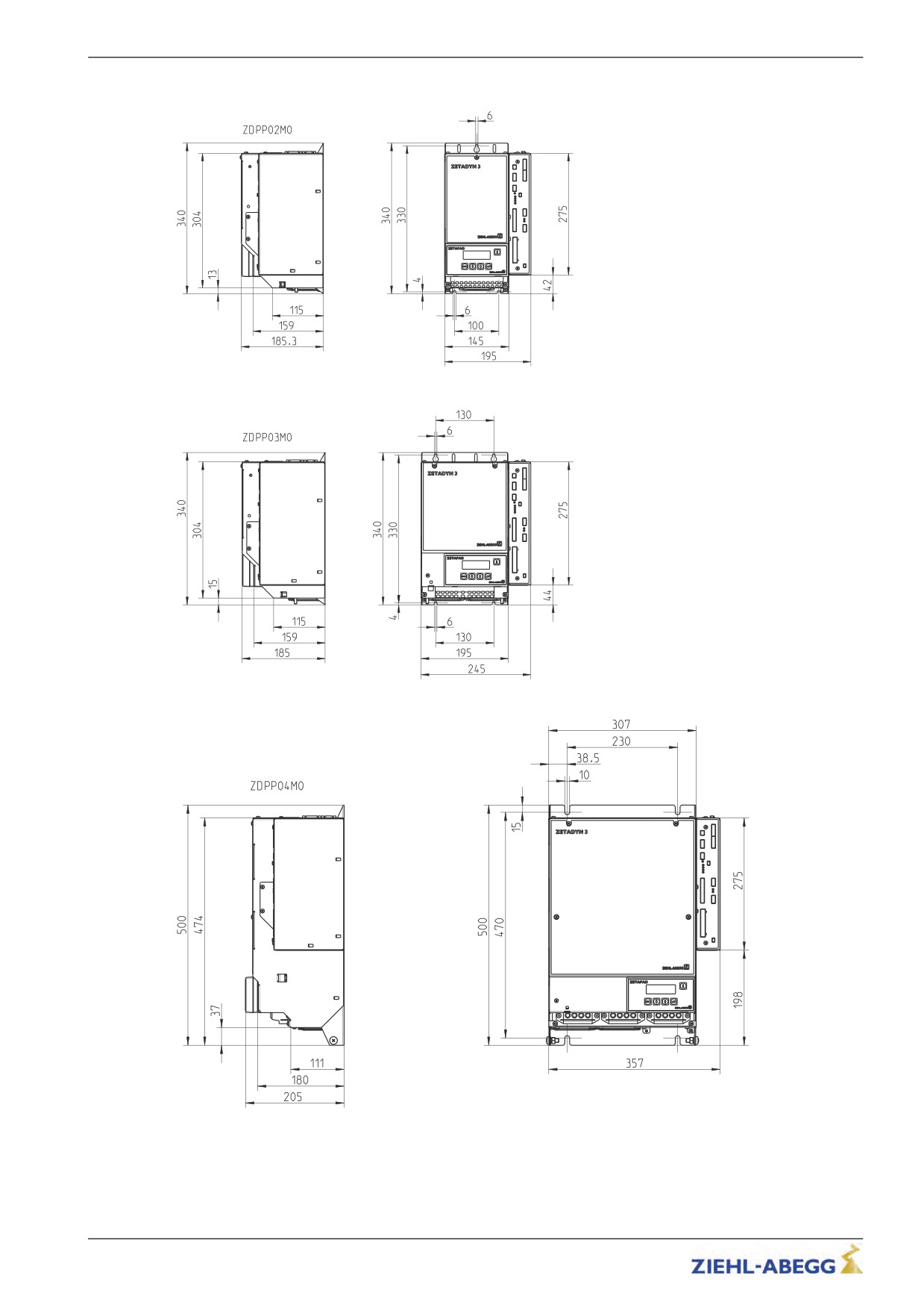
Dimensions
Dimensions ZETADYN 3BF011 up to ZETADYN 3BF017
Dimensions ZETADYN 3BF023 up to ZETADYN 3BF040
Dimensions ZETADYN 3BF050 up to ZETADYN 3BF074
14/200
Mechanical installation
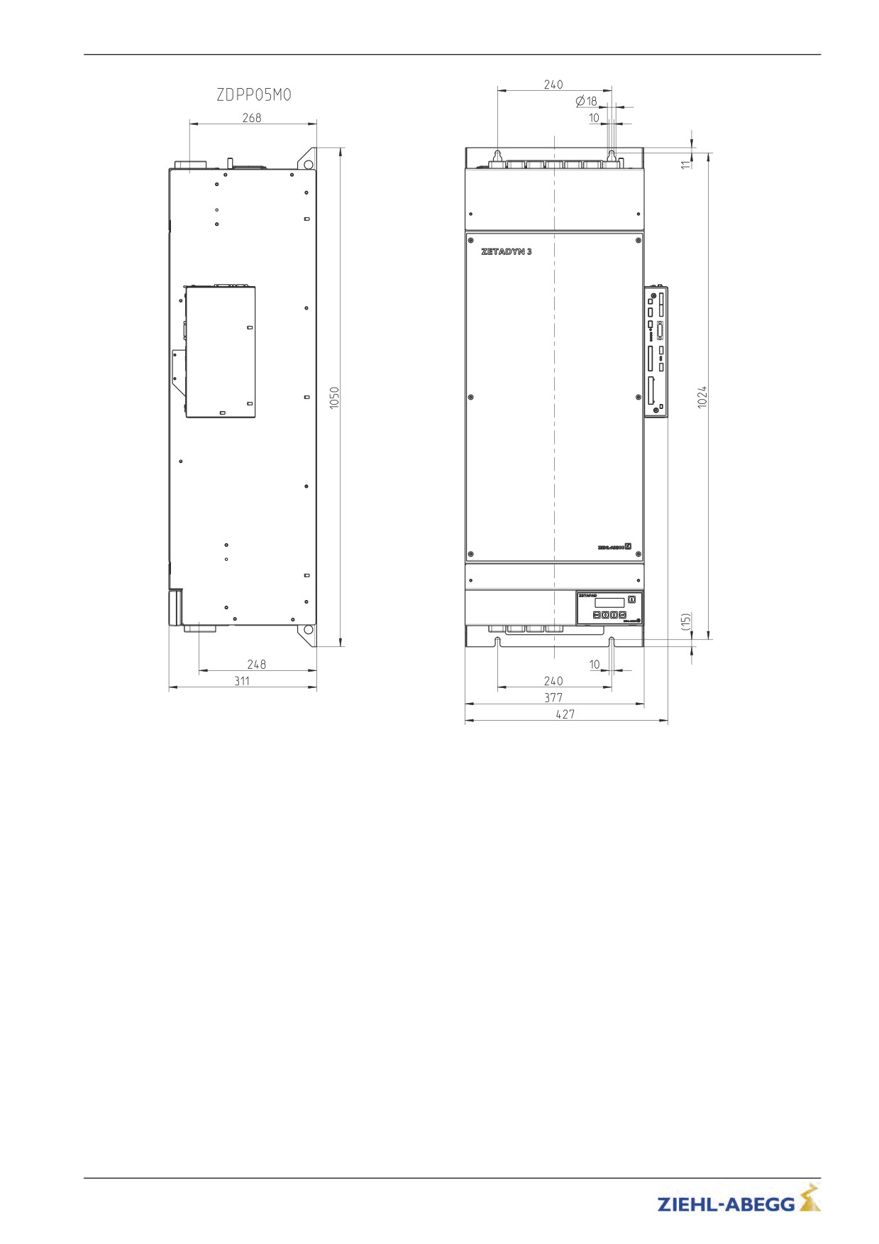
Dimensions ZETADYN 3BF110 up to ZETADYN 3BF180
15/200
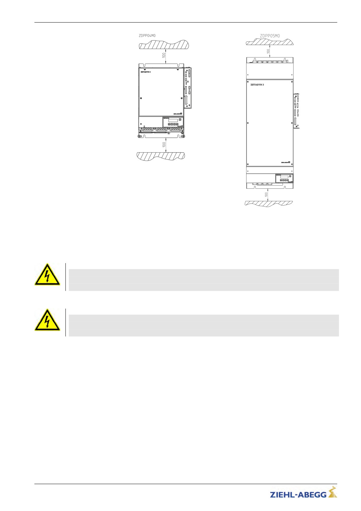
Electrical installation
Minimum distances ZETADYN 3BF011 up to ZETADYN
3BF180
5
Electrical installation
Danger!
It is forbidden to carry out work on electrically live parts.
Even after disconnection, the DC-link ( terminals X1: +DC / X1:-DC ) are still live.
Wait at least 3 minutes before working on the device
Danger!
Operating the ZETADYN 3BF with the housing cover removed is prohibited because energized,
exposed parts are present inside the device. Disregarding this regulation can lead to severe personal
injury.
Work on electric components may only be carried out by trained electricians or by persons instructed
in electricity under the supervision of an electrician in accordance with electrical engineering regula-
tions.
A second person must always be present when working on energized parts or lines who disconnects
in case of emergency.
Inspect electrical equipment periodically: retighten loose connections - immediately replace damaged
lines and cables.
Always keep switch cabinets and all electrical supply facilities locked. Access is only allowed for
authorized persons using a key or special tool.
Never clean electrical equipment with water or similar liquids.
16/200
Electrical installation
5.1
EMC-compatible installation
When correctly installed (see below), the device corresponds to the following standards:
• EN 12015 Electromagnetic compatibility - Product family standard for lifts, escalators and moving
walks - Emission
• EN 12016 Product family standard for lifts, escalators and moving walks - Immunity
The following points must be observed if the above mentioned standards are to be adhered to:
• Integrate power choke and radio interference filter into the mains line
• Use only shielded cables for motor and brake chopper or brake resister connections.
• Max. motor line length is 25m
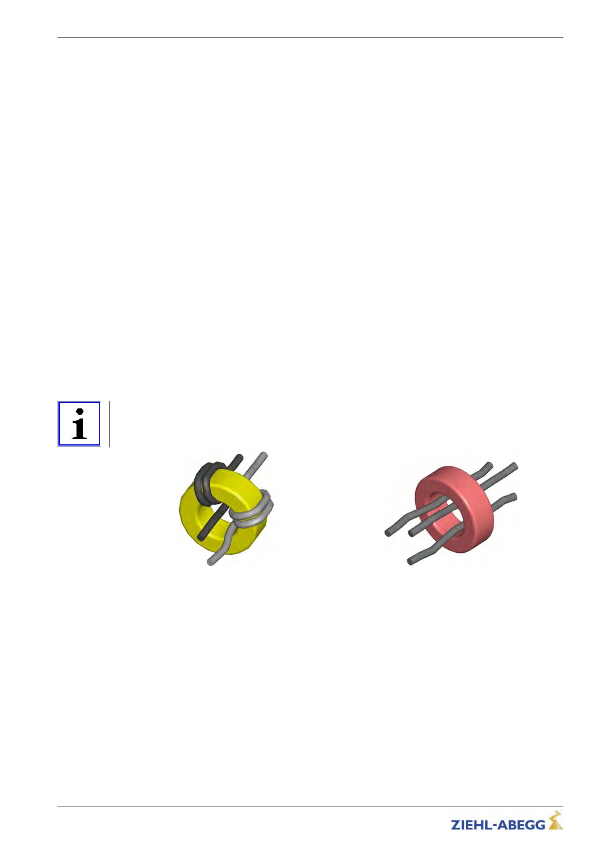
• Wind unshielded cables of brake resistors type BR09-1 and BR11-A around the toroidal core
provided (see figure)
• Feed the motor cables at output U/V/W of the frequency converter through the toroidal core
provided (see figure)
• If you must interrupt the shielding on a cable (e.g., to install a motor contactor), the shielding must
be subsequently continued with the lowest possible HF impedance.
• Use only shielded control cables
• The shielding of control cables (inputs and outputs, rotary encoder cable, etc.) must be connected
to earth potential on the inverter side
• The shielding of control cables (inputs and outputs, rotary encoder cable, etc.) must be connected
to earth potential on the inverter side
• Use shielded lines in the switching cabinet also
• Do not twist shielding for connections; use a suitable shield connection system (e.g. Shield-Kon®)
• Run the control cables and the encoder cables separate from the power cables
• Flawless electrical contact must exist between the grounded mounting plate and the metal housing
of the frequency inverter
• Provide connected inductances (brakes, motor contactors) with suppressors
Information
Please contact the manufacturer for information on adhering to the limit value class B in accordance
with EN 55011.
Toroidal core in BR09-1 and BR11-A
Toroidal core for motor cable
17/200
Electrical installation
5.1.1
EMC-compatible assembly of the control cabinet
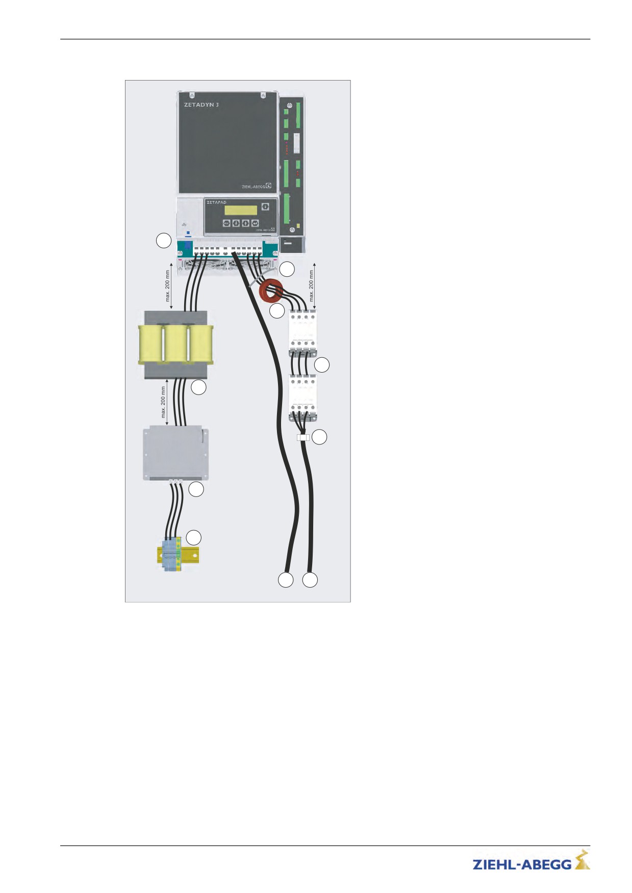
The following points must be observed if the in
chapter 5.1 mentioned standards are to be adhered
to:
• see chapter 5.1
•
Leadlength between radio interference filter and line
reactor max. 200mm
• Leadlength between line reactor and ZETADYN 3BF
max. 200mm
• Leadlength between ZETADYN 3BF and 1. motor
contactor max. 200mm
• Assemble the mains line (incl. mains connection,
radio interference filter and line reactor) seperate from
the brake resistor cable and the motor contactors
(incl. motor cable)
4
9
5
6
3
10
2
1
7
8
1
Mains connection
2
Radio interference filter FEF
3
Line reactor
4
5
Toroidal core for motor cable
6
Motor contactors
7
Brake resistor cable (shielded)
8
Motor cable (shielded)
9
Shielding (brake resistor cable)
10
Cable clamp (shielded)
18/200
Electrical installation
5.2
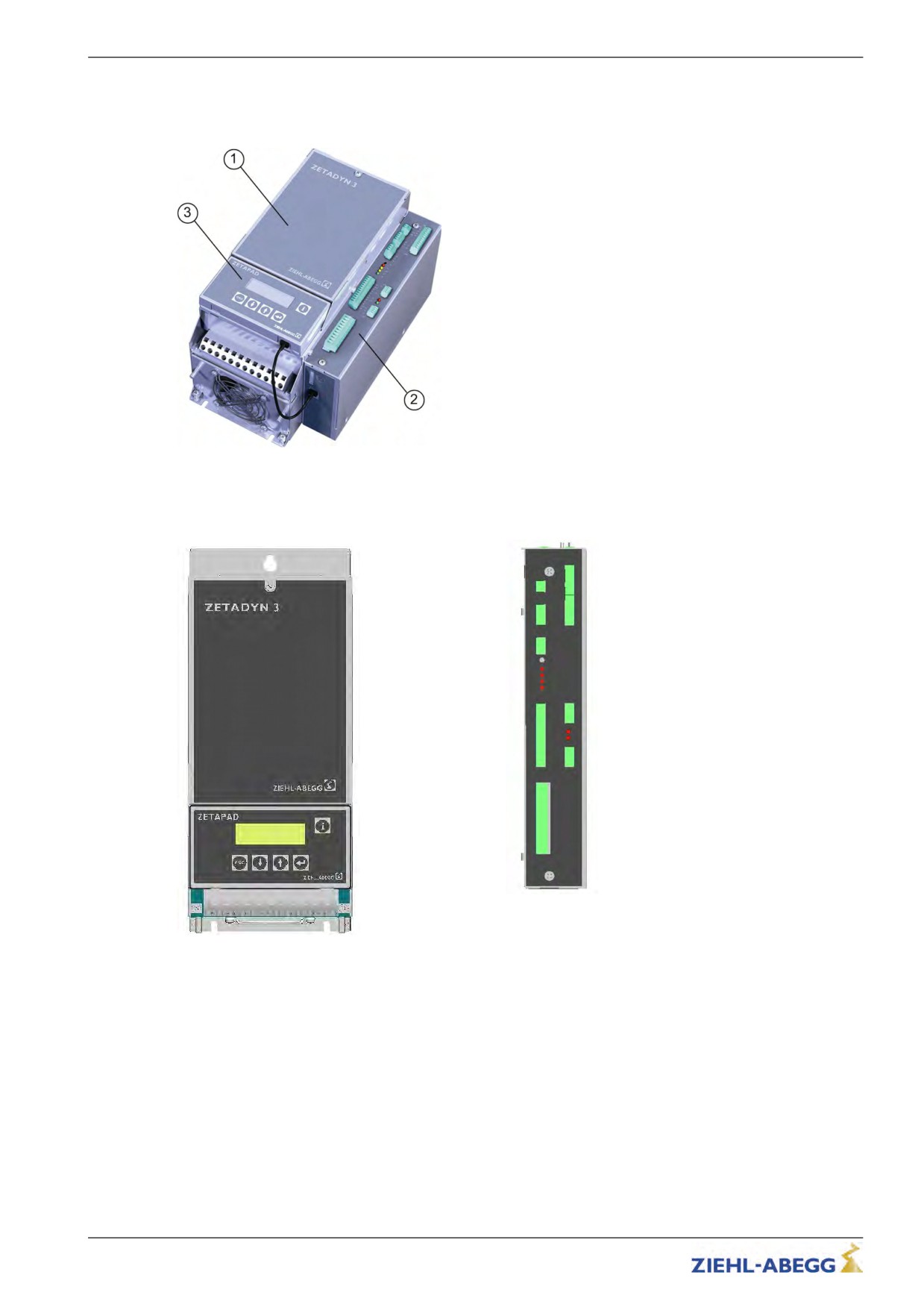
Device set-up / Position of connection terminals
5.2.1
ZETADYN 3C011 to 3C074
Configuration ZETADYN 3BF011 to 3BF074
1
Power unit
2
Controller unit (with open loop control inputs and control outputs)
3
Operating terminal ZETAPAD
X-MT X-ENC8 / X-ENC9 / X-ENC15
X-BR
X-EXT
X-ENCO
X-BC
X-CO
X-CAN / X-AN
X-I
X-DCP
X-O
X1
X-MMC X-PAD
Terminal positions
X1
Mains / Motor / Brake-Chopper / Brake-Resistor
X-EXT external 24 V external power supply
X-BC Allocation of Brake-Chopper / Brake-Resistor
X-CO Contactor monitoring
X-I Digital inputs
X-O Digital outputs
X-MMC Memory card
X-PAD ZETAPAD
X-DCP DCP
X-CAN CAN
X-ENCO Artificial encoder
X-BR Motor brake monitoring
X-ENC8
Encoder
X-ENC9
Encoder SUB-D
X-ENC15
Absolute encoder SUB-D
19/200
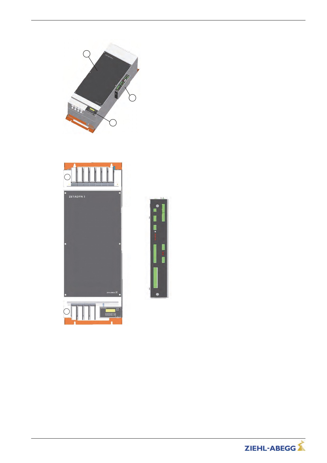
Electrical installation
5.2.2
ZETADYN 3BF110 to 3BF180
1
2
3
Configuration ZETADYN 3BF110 to 3BF180
1
Power unit
2
Controller unit (with open loop control inputs and control outputs)
3
Operating terminal ZETAPAD
2
X-MT X-ENC8 / X-ENC9 / X-ENC15
X-BR
X-EXT
X-ENCO
X-BC
X-CO
X-CAN / X-AN
X-I
X-DCP
X-O
X-MMC
1
Terminal positions
1
Mains connection
2
Motor / brake chopper / brake resistor
X-EXT external 24 V external power supply
X-BC Allocation of Brake-Chopper / Brake-Resistor
X-CO Contactor monitoring
X-I Digital inputs
X-O Digital outputs
X-MMC Memory card
X-PAD ZETAPAD
X-DCP DCP
X-CAN CAN
X-ENCO Artificial encoder
X-BR Motor brake monitoring
X-ENC8
Encoder
X-ENC9
Encoder SUB-D
X-ENC15
Absolute encoder SUB-D
20/200
Electrical installation
5.3
Protective ground connection
The device has a defined leakage current of > 3.5 mA according to DIN EN 60990. For this reason its
connection has to be fix. According to EN 50178 point 5.2.11 or 5.3.2.1 the earth conductor has to
have a cross section of 10 mm² or more. If an earth conductor with a cross section < 10 mm² is used,
there has to be a second earth conductor. Then the cross section of both earth conductors added has
to be 10 mm² or more. For the connection of the earth conductors there are threaded bolts M6 at the
frequency inverter (see picture).
Protective ground connection ZETADYN 3BF011 up to
Protective ground connection ZETADYN 3BF0050 up to
ZETADYN 3BF040
ZETADYN 3BF074
5.4
Mains connection (X1)
Danger!
Before connecting to the mains, check if the technical data on the rating plate of the ZAdyn4C
correspond to the required connection values.
5.4.1
Network form
The mains filter and frequency converter are designed for use in an earthed supply system. Permis-
sible network forms are:
• TN network
• TT network
Information
The mains filter and frequency converter are unsuitable for use in the IT network!
5.4.2
Cable cross section
The line cross-section must be specified dependent on the motor’s rated current and the ambient
conditions (e.g. temperature, wiring method) in accordance with DIN VDE 0100.
5.4.3
Mains fuse
The fuse protection is implemented in accordance with the line cross-section used
5.4.4
Type of cable
Both rigid and flexible lines can be utilized. The use of wire-end sleeves is recommended for flexible
lines.
The mains line does not have to be shielded.
5.4.5
Connection
Type ZETADYN 3BF011 bis ZETADYN 3BF040
The mains connection is designed with spring contact terminals. To avoid damage to the connection
terminals and to ensure a safe contact, a suitable screwdriver must be inserted into the terminals as
far as it will go to fully open them when connecting cables.
21/200
Electrical installation
Type ZETADYN 3BF050 up to ZETADYN 3BF074
The mains connection is implemented with screw terminals. To prevent damage to the terminals and
to ensure good contact, the terminals must be tightened with the torque as stated in the technical
data.
Type ZETADYN 3BF110 bis ZETADYN 3BF180
The mains connection is implemented with screws M12 for ring terminals. To prevent damage to the
cables and the connecting screws and to ensure good contact, the terminals must be tightened with
the torque as stated in the technical data.
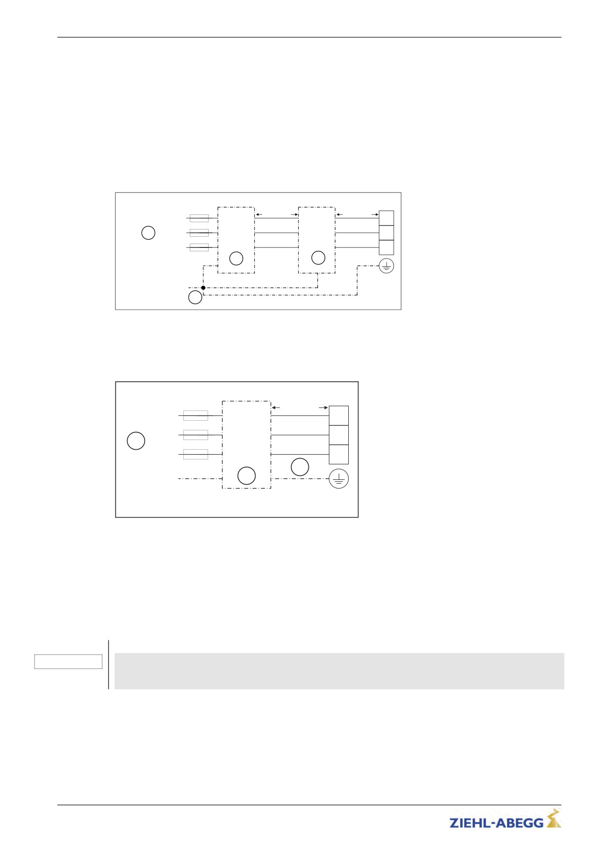
X1
FEF
max. 200 mm
ND
max. 200 mm
L1
L1
L1.1
U1
U2
L1
1
L2
L2
L2.1
V1
V2
L2
L3
L3
L3.1
W1
W2
L3
2
3
PE
4
Mains connection ZETADYN 3BF011 und ZETADYN 3BF050-074
1
Mains 3~ 400V/PE/50Hz
2
Radio interference filter FEF
3
Line reactor ND
4
Central ground point
X1
max. 200 mm
L1
L1
L1.1
L1
L2
L2
L2.1
L2
1
L3
L3
L3.1
L3
3
PE
2
Mains connection ZETADYN 3BF013 - 040
1
Mains 3~ 400V/PE/50Hz
2
Line reactor-radio interference filter
3
Prefabricated connection wires
5.5
Line reactor-radio interference filter
Installation in the mains feed to comply with:
• EN 12015 Electromagnetic compatibility - Product family standard for lifts, escalators and moving
walks - Emission
• EN 12016 Product family standard for lifts, escalators and moving walks - Immunity
When the frequency inverter is operated without a power choke, the harmonic limit values quoted in
CAUTION!
product family standard EN12015 are not met. The service life of the device is also considerably
shorter.
The line reactor and the radio interference filter are two separate components which have to be
mounted in the switch cabinet.
With the line reactor radio-interference filter from ZIEHL-ABEGG, compliance with these standards
and directives is guaranteed.
Connection diagrams showing the connection of the line reactor and the radio interference filter can
be found in the chapter "Electrical installation / line connection (X1)".
22/200
Electrical installation
5.6
Residual current operated device (RCCB)
Frequency inverters of the ZAdyn type require no FI circuit breaker for operation.
The circuit at the ZETADYN 3BF output is monitored by an electronic short-circuit protection. On
detecting a short-circuit current at the output of the ZETADYN (and thus negligible impedance
between the phase and a body or the protective earth of the circuit or a protective earth of the
operating medium in the case of an error) the output current is switched off within a time of <20 μs. On
condition that the potential equalisation for the ZETADYN and the motor was performed according to
the valid standards (VDE0100-Part 540:2012-06 and DIN EN 50178:1997), this behaviour is sufficient
for the automatic switch-off in case of an error demanded by VDE 0100-4100.
If an FI circuit breaker is required for special reasons (e.g. fire prevention), an all-current sensitive FI
circuit breaker type B must be used. For maximum operational reliability ZIEHL-ABEGG recommends
the use of an FI circuit breaker with reference fault current of 300 mA for fire prevention according to
regulation VdS 3501.
Information
Please note that even when using a correct type B RCCB, false triggering due to high protective earth
currents (stray current) can still occur and that operation with these protective devices is not possible.
5.7
Control transformer in the mains feed line
Caution!
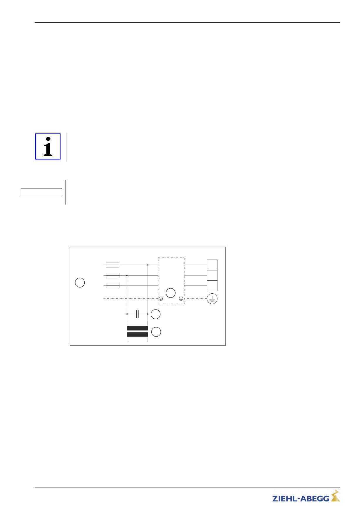
When using a control transformer in the frequency inverter’s mains supply line, you must connect a
CAUTION!
capacitor parallel to the transformer’s primary winding (see Fig.).
The capacitor is used to prevent an extreme increase in voltage in case the voltage fails in one of the
phases to which the transformer is connected. This voltage increase can lead to destruction of the line
filter. The cause of voltage increases is resonance of the control transformer with the radio-interfer-
ence suppression components, which are always used in frequency inverters.
X1
L1
L1
L1.1
L1
L2
L2
L2.1
L2
1
L3
L3
L3.1
L3
2
PE
Cx
3
0V
400V
4
0V
230V
Control transformer in the mains feed line
1
Mains 3~ 400V/PE/50Hz
2
Line reactor-radio interference filter
3
Capacitor
4
Control transformer
Recommended capacitor types for Cx:
• Epcos Typ B25832 10µF/640V-AV
• Condensers for motor starting with following data: 10µF/450V-AC
In addition, you must comply with the following:
• During sequential disconnection, switch off the phase on which the transformer is operated last
• Do not oversize the transformer
• If a loaded and an intermittently unloaded transformer is operated in the open loop control, operate
these on the same phases
23/200
Electrical installation
5.8
Motor connection (X1)
5.8.1
Cable cross section
The line cross-section must be specified dependent on the motor´s current and the ambient conditions
(e.g. temperature, wiring method) in accordance with DIN VDE 0298-4.
5.8.2
Type of cable
Always use shielded cables for the motor connections! Both rigid and flexible lines can be installed.
The use of wire-end sleeves is recommended for flexible lines.
5.8.3
Cable length
The maximum line length is 25 m. With a motor line of >25 m compliance with DIN EN 12015 (electro-
magnetic compatibility - interference emission and DIN EN 12016 (electromagnetic compatibility -
interference immunity) can no longer be guaranteed.
5.8.4
Connection
Type ZETADYN 3BF011 bis ZETADYN 3BF040
The mains connection is designed with spring contact terminals. To avoid damage to the connection
terminals and to ensure a safe contact, a suitable screwdriver must be inserted into the terminals as
far as it will go to fully open them when connecting cables.
Type ZETADYN 3BF050 up to ZETADYN 3BF074
The mains connection is implemented with screw terminals. To prevent damage to the terminals and
to ensure good contact, the terminals must be tightened with the torque as stated in the technical
data.
Type ZETADYN 3BF110 bis ZETADYN 3BF180
The mains connection is implemented with screws M12 for ring terminals. To prevent damage to the
cables and the connecting screws and to ensure good contact, the terminals must be tightened with
the torque as stated in the technical data.
5.8.5
Motor contactors
Select the motor contactors depending on the type of motor and the corresponding motor data.
According to DIN EN 81-1, the motor contactor contacts must be self-commutated.
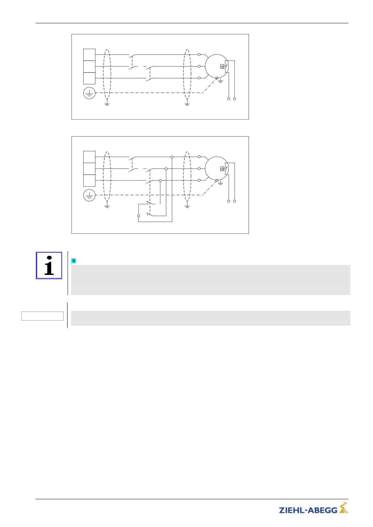
When operating asynchronous motors, two master contactors per at least 2 main contacts (make
contact element, NO contact) are required for the motor connection and 2 auxiliary contacts (NO
contacts) for contact monitoring (see wiring diagram).
For operating synchronous motors 1 main contactor with 4 main contacts (2x normally open and 2x
normally closed) and 2 main contactors with at least 2 main contacts (normally open) are required for
the motor connection. Both main contactors require 2 auxiliary contacts each (normally open) for
contactor monitoring (see connection diagram).
The maximum line length to the motor contactors when using non-shielded lines is 200mm. If there is
a greater distance between the contactors and frequency inverter, you must use shielded lines!
Danger!
Whenoperatingthemotorwithanencoder,the feed line to the motor must be connected on the motor and
inverter side phase-correct: U R U / V R V / W R W.
Never swap the connection; not even if the rotary direction of the motor is false!! If the motor phases
are swapped, motor control is generally not possible. This can lead to jerky movements or uncon-
trolled acceleration of the motor.
24/200
Electrical installation
X1
K1
3
4
U
U
K2
M
1
2
3
4
V
V
3~
1
2
W
W
P1
P2
Asynchronous motor connection
X1
K1
3
4
U
U
K2
M
1
2
3
4
V
V
3~
1
2
W
W
P1
P2
R4 R3
R2 R1
Synchronous motor connection
Information
If an emergency evacuation is carried out by opening the brakes, the motor windings must be
short-circuited for the evacuation to prevent an uncontrolled acceleration of the elevator. The
short-circuit generates a speed-dependent braking torque, sufficient in most cases to limit the
elevator speed to a safe level.
CAUTION!
If operating with synchronous motors from other manufacturers, you have to ensure that a manually
emergency evacuation is approved.
5.8.6
Contacting the shielding in the switch cabinet
You must connect the shielding on the switch cabinet side in to the PE near the contactors
5.8.7
Contacting the shielding on the motor
Connect the shielding on the motor side to the PE junction that is located directly on the motor
housing.
For pre-assembled motor cables from ZIEHL-ABEGG, the shield connection terminal is provided with
a ring cable lug for the corresponding thread size.
When using non-prefabricated lines, implement the shielding connection by using a suitable shielding
connection system (e.g. Shield-Kon®).
25/200
Electrical installation
5.9
Motor temperature monitoring (X-MT)
Information
The frequency inverter must be equipped with the option module EM3-MOT-TEMP (item no. 357108)
for motor temperature monitoring!
Information
The detection of over temperature of the motor doesn't cause a drive interruption. The current drive
will be completed.
If an over temperature of the motor will be detected at stop, there is no further drive possible.
The temperature monitoring is carried out according to IEC 61800-5-1:2003-02 (switching point at
3500 Ω)
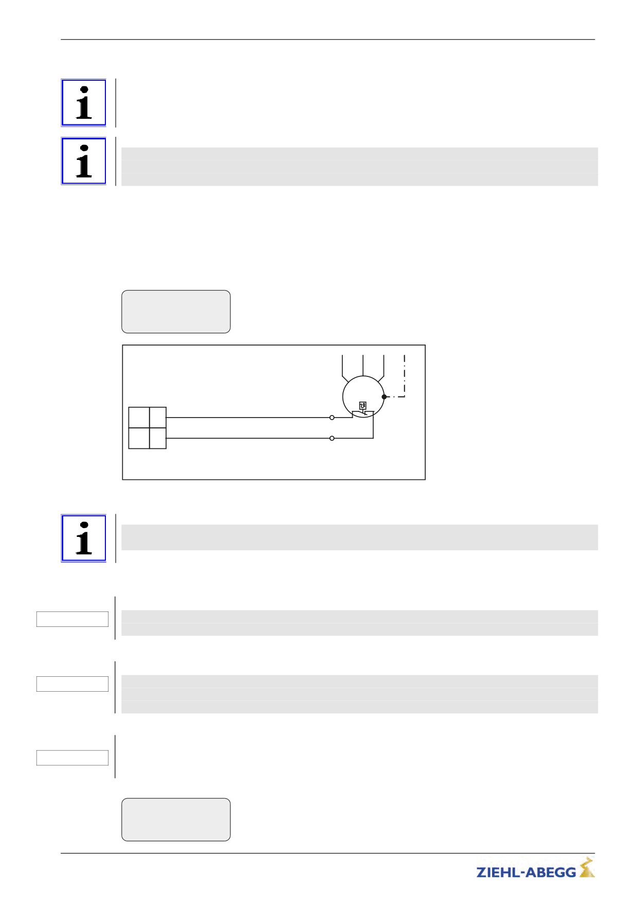
The following sensor types can be used:
• PTC thermistor (PTC according to DIN 44082)
• Temperature sensor KTY84-130
• Thermal circuit breaker
The used sensor has to be parametrized in the menueMonitoring/P1P2!
Monitor
|-" P1P2
On
|-"
On
Motor temp. monitor
U
V
W PE
M
3~
X-MT
P1
P1
(P1)
P2
P2
(P2)
Temperature monitoring connection
() terminal designation of connector
Information
If the temperature monitor is not used, it must be switched off (Monitors/P1P2=Off). Short-circuiting
of the inputs P1 and P2 is detected as a fault by the ZETADYN 3C.
5.10
Brake-Resistor (X1)
Caution!
An existing temperature monitor absolutely must be connected to the frequency inverter!
CAUTION!
Otherwise, the device could burn up during a malfunction!
Caution!
If the connection of a brake resistor (type BRxx) to the +DC and -DC terminals is faulty, it will emit a
CAUTION!
continuous power output and the device will become overheated. If a temperature monitor is not
connected, the device will burn out!
Caution!
CAUTION!
The brake resistor or brake chopper used must be configured in the menu Encoder & BC /BC_TYP.
Encoder & BC
|-" BC_TYP BR25
|-"
BR25
BR/BC - Typ
26/200
Electrical installation
Type BR11-A
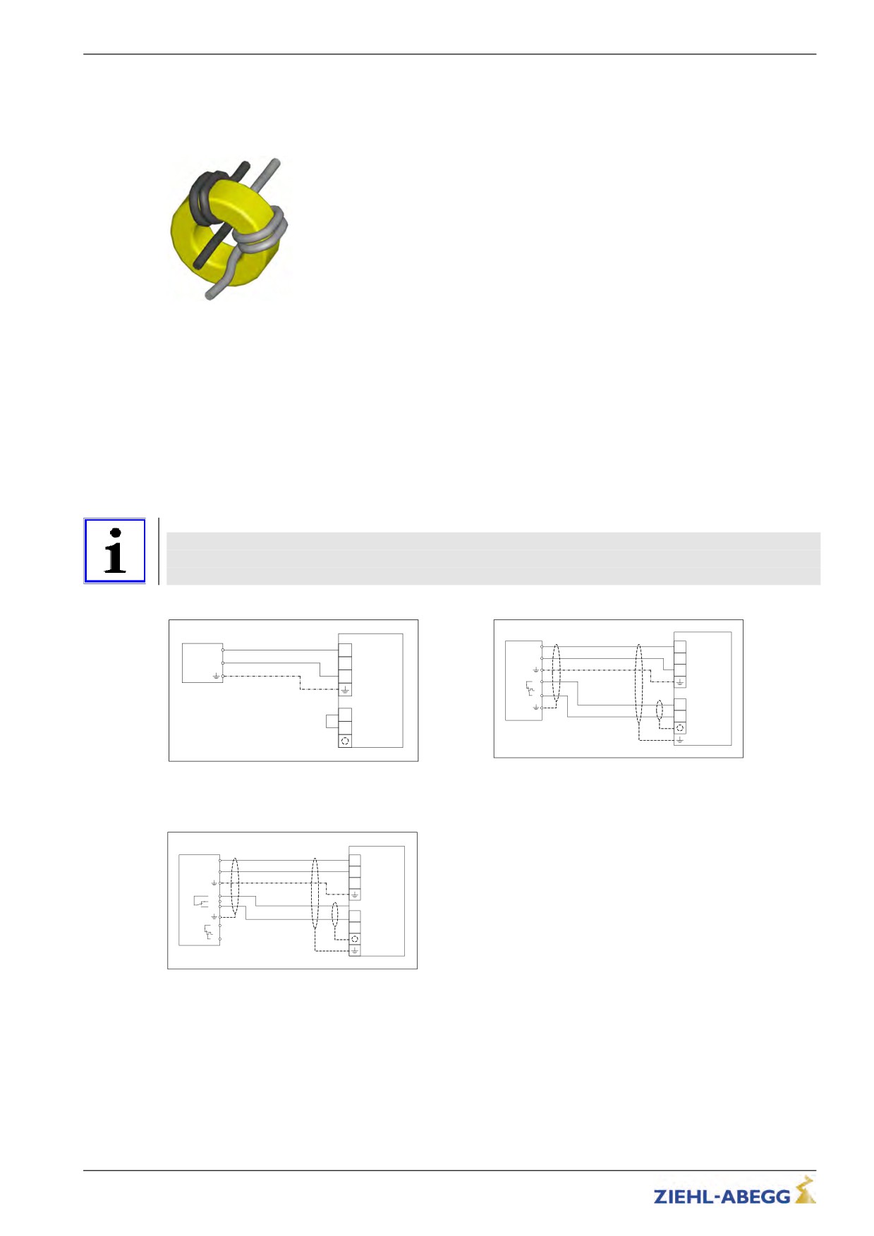
The brake resistor of the type BR11-A is equipped with prefabricated cables. These must be wound
around the delivered toroidal core (see fig.).
Toroidal core BR11-A
Cable length
The maximum line length is 5 m.
When lines over >5 m are used, compliance with DIN EN 12015 (electromagnetic compatibility -
electrical interference) and DIN EN 12016 (electromagnetic compatibility - noise immunity) is no
longer guaranteed.
If the11pre-fabricated5cable is not long enough in the brake resistor of the BR11-A type, this can be
extended up to a length of 5 m.
A shielded, self-extinguising cable is required for this.
Brake-Resistor connection
Information
The brake resistor of the BR11-A type has no temperature monitor.
An electrical connection must be made at the ZETADYN 3BF between XBC:+24V and XBC:BR
(see fig.)!
X1/X3
X1/X3
BR
+DC
+DC
BR
+DC
+DC
R
-DC
R
-DC
R
R
TB1
TB2
X-BC
X-BC
+24V
+24V
BC
BC
BR11-A connection
Installation position BR17 / BR25 / BR50 / BR100
1
Max. contact load: 5 A / 250 VAC
Brake-Chopper connection
X1/X3
BC
ZK+
+DC
ZK-
-DC
R
ST11
ST12
ST14
X-BC
+24V
TB1
BC
TB2
BC25 / BC50 connection
1
Max. contact load: 5 A / 250 VAC
27/200
Electrical installation
5.11
Digital inputs (X-IN)
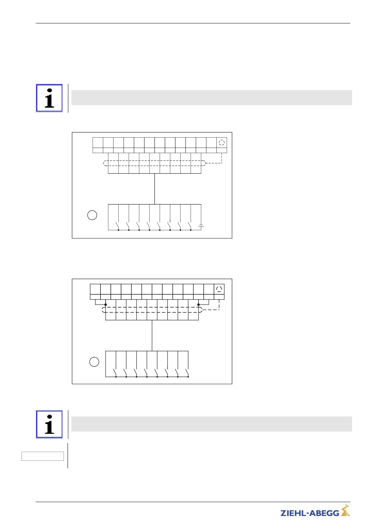
Standard, there are digital inputs available on the X-IN 8 terminals for parallel activation of the
frequency inverter. The inputs are pre-parameterized but can be assigned with other functions by
modifying the parameters
The inputs can be activated galvanically isolated by an external 24 V power supply in the control
system or by the internal 24 V supply in the frequency inverter.
Information
Use shielded cables for the connections. The shielding must be connected to the terminal X-IN
shielding connection.
5.11.1
Connection with external power supply
+24V
+24V
I01
I02
I03
I04
I05
I06
I07
I08
GND
GND
_IN
_IN
X-IN
(1)
(2)
(3)
(4)
(5)
(6)
(7)
(8)
(9)
(10)
(11)
(12)
(13)
1*
2*
3*
4*
5*
6*
7*
8*
9*
10*
1*
2*
3*
4*
5*
6*
7*
8*
9*
10*
1
0V
+24V
Connection of digital input with external power supply
1
Modulation
()
terminal designation of connector
5.11.2
Connection with internal power supply
+24V
GND
+24V
I01
I02
I03
I04
I05
I06
I07
I08
GND
X-IN
_IN
_IN
(1)
(2)
(3)
(4)
(5)
(6)
(7)
(8)
(9)
(10)
(11)
(12)
(13)
1*
2*
3*
4*
5*
6*
7*
8*
9*
10*
1*
2*
3*
4*
5*
6*
7*
8*
9*
1
Connection of digital input with internal power supply
1
Modulation
()
terminal designation of connector
Information
When using the internal power supply, you must make a bridge between both 24V terminals
and both 0V terminals.
Caution!
The internal 24V power supply is provided solely for the digital inputs. Switching consumer load with
CAUTION!
this voltage is prohibited!
28/200
Electrical installation
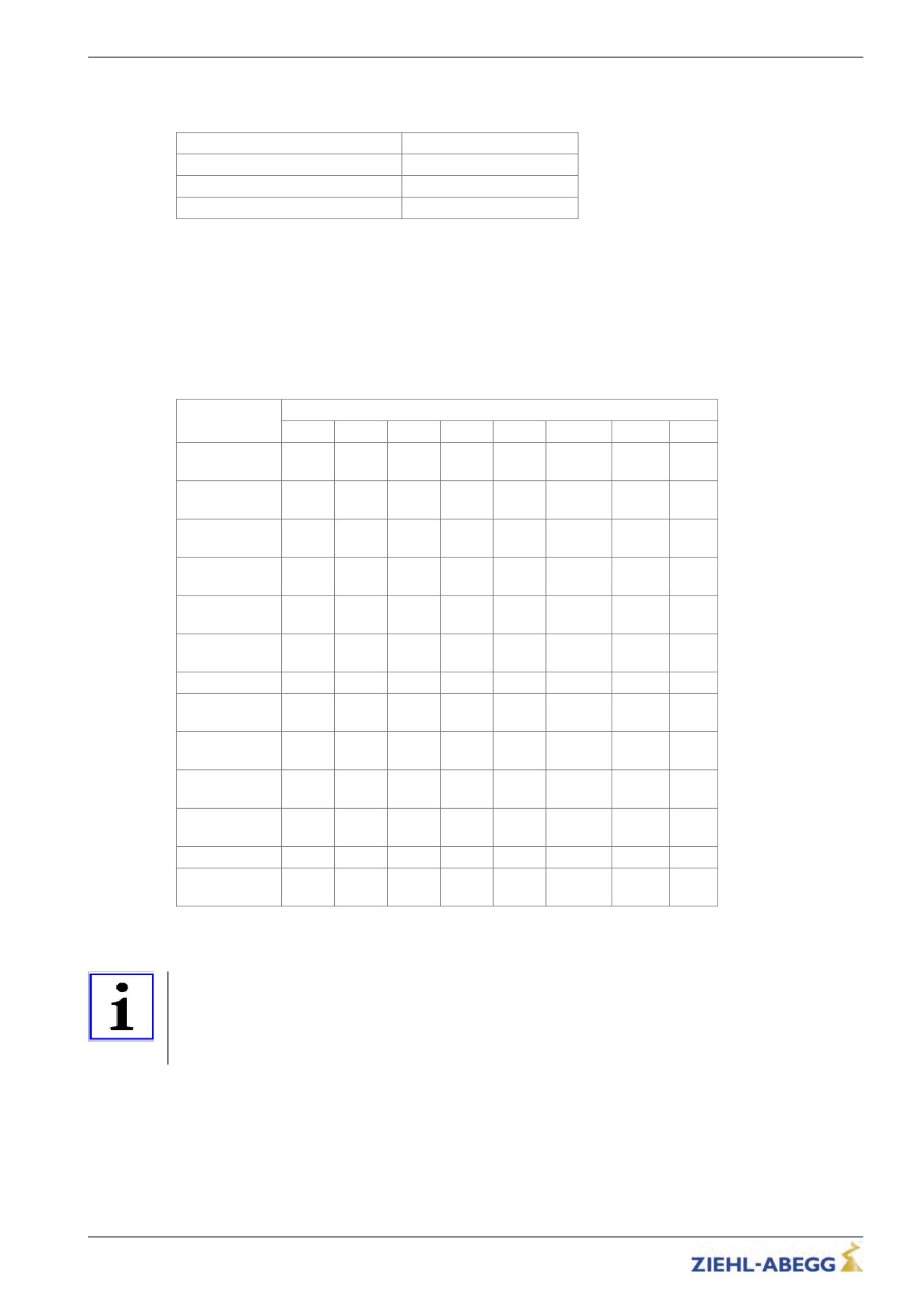
5.11.3
Technical data
The digital inputs comply with the IEC61131-2 TYPE 2 industry standard.
Voltage range
+22 ... 26 VDC
Switching level low/high
<5 VDC / >11 VDC
Current consumption at 24 V
typ. 12.6 mA
Clamping range
max. 1,5 mm²
5.11.4
Terminal assignment X-IN
You can configure the inputs I1 … I8 assignments. The configuration can be implemented by:
• Presetting the used control system (assignment corresponding to the control requirements)
• Free configuration
Implement configuration of the digital inputs in the Control system\CONFIG menu.
The input assignments dependent on the configuration:
Inputs
Configuration
I01
I02
I03
I04
I05
I06
I07
I08
RV2
00:Free
RF*
V1*
V2*
V3*
VZ*
RV1 UP*
Free*
DOWN*
RV2
01:ZA_IO
RF
V1
V2
V3
VZ
RV1 UP
Free*
DOWN
RV2
03:BP_IO
RF
V1
V2
V3
VZ
RV1 UP
Free*
DOWN
RV2
08:KN_IO
RF
V1
V2
V3
VZ
RV1 UP
Free*
DOWN
RV2
11:NL_IO
RF
V1
V2
V3
VZ
RV1 UP
Free*
DOWN
RV2
13:SS_IO
RF
V1
V2
V3
VZ
RV1 UP
V4*
DOWN
15:ZA_BIN
RF
DIR
BIN0
BIN1
BIN2
Free*
Free*
Free*
RV2
16:WL_IO
RF
V1
V2
V3
VZ
RV1 UP
Free*
DOWN
RV2
21:ST_IO
RF
V1
V2
V3
VZ
RV1 UP
Free*
DOWN
RV2
24:CSILVA
RF
BIN0
BIN1
BIN2
Free
RV1 UP
Free*
DOWN
RV1
RV2
25:S+S
SBIN2
SBIN1
SBIN0
Free*
Free*
RF
UP
DOWN
27:MAS_BIN
RF
DIR
MBIN0
MBIN1
MBIN2
BR1
BR2
Free*
RV2
30:KS_IO
RF
V1
V4
V2
VZ
RV1 UP
V3*
DOWN
* The function of the inputs can be changed
Information
To be able to travel, at least the following input signals need to be present:
• Controller enable
• Speed
• Direction default
29/200
Electrical installation
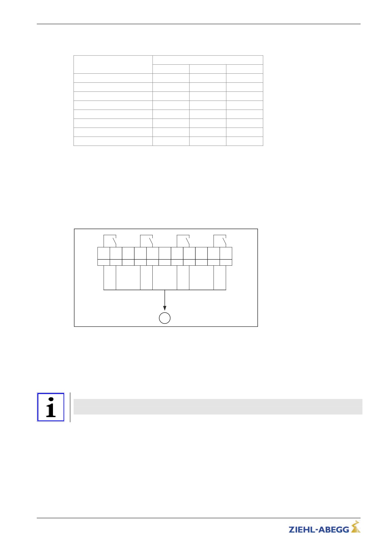
5.11.5
Binary traveling speed default
Standard (CONFIG=15:ZA_BIN)
Binary inputs
Travel speed V_3
BIN2
BIN1
BIN0
-
0
0
0
V1
0
0
1
V2
0
1
0
V3
0
1
1
V4
1
0
0
V5
1
0
1
V6
1
1
0
V7
1
1
1
5.12
Digital outputs (X-OUT)
5.12.1
Digital outputs X-OUT
The connection terminal X-OUT is equipped with 4 digital outputs as zero potential relay contacts with
normally open function. The functions of the outputs are pre-parameterised but can be assigned other
functions by changing the parameters.
5.12.1.1
Connection X-OUT
X-OUT
O11
O14
O21
O24
O31
O34
O41
O44
(1)
(2)
(3)
(4)
(5)
(6)
(7)
(8)
(9)
(10)
(11)
1
Connection of the digital outputs X-OUT
1
Modulation
()
terminal designation of connector
5.12.2
Digital output X-BC:PWM
The connection terminal X-BC is equipped with 1 digital output, connection PWM, with normally open
function. The functions of the output is pre-parameterised but can be assigned another function by
changing the parameter.
Information
ATTENTION! The PWM output does not have zero potential. The GND potential of the internal 24 V
mains supply is connected!
30/200
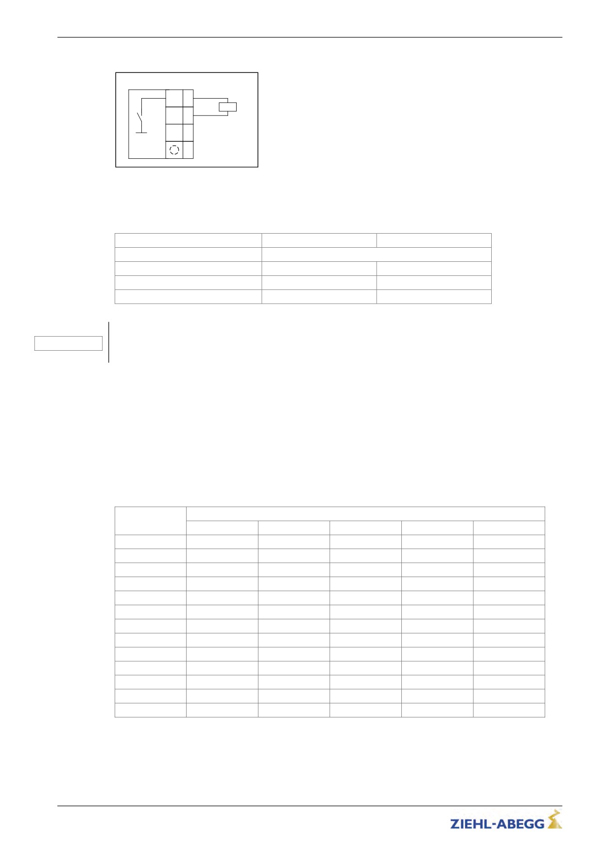
Electrical installation
5.12.2.1
Connection PWM
X-BC
PWM
(1)
Kx
24V
(2)
BC
(3)
(4)
Connection of the digital output PWM
Kx Control relay
() terminal designation of connector
5.12.3
Technical data
X-OUT
X-BC (PWM)
Short-circuit-proof
no*
Min. switching capacity
5 mA / 12 VDC
5 mA / 24 VDC
Max. switching capacity
2 A / 250 VAC
50 mA / 24 VDC
Cable cross section
max. 2.5 mm²
max. 1,5 mm²
Caution!
CAUTION!
* In order to protect the relay contacts, switched inductivities must be provided with an external
suppressor circuit (suppressor diode, RC element).
5.12.4
Terminal assignment X-OUT
The output assignments can be configured. The configuration can be implemented by:
• Presetting the used control system (assignment corresponding to the control requirements)
• Free configuration
Implement configuration of the digital outputs in the Control system\CONFIG menu.
Please refer to the "Parameter list / Control menu" chapter for a description of the individual parame-
ters
The output assignments dependent on the configuration:
Outputs
Configuration
O11 - O14
O21 - O24
O31 -O34
O41 - O44
PWM
00:Free
Fault*
MB_Brake*
MotContact*
V < V_G1*
AUS*
01:ZA_IO
Err
MB_Brake
MotContact
V < V_G1
AUS
03:BP_IO
Err
MB_Brake
MotContact
V < V_G1
AUS*
08:KN_IO
Err
MB_Brake
MotContact
V < V_G1
AUS*
11:NL_IO
Err
MB_Brake
MotContact
V < V_G1
AUS*
13:SS_IO
Err
MB_Brake
MotContact
V < V_G1
AUS*
15:ZA_BIN
Err
MB_Brake
MotContact
V < V_G1
AUS*
16:WL_IO
Err
MB_Brake
MotContact
V < V_G1
AUS*
21:ST_IO
Err
MB_Brake
MotContact
V < V_G1
AUS*
24:CSILVA
Err
MB_Brake
MotContact
V < V_G1
AUS*
25:S+S
MotContact
MB_Brake
V=O
Err
AUS*
27:MAS_BIN
Err
MB_Brake
MotContact
Off*
AUS*
30:KS_IO
Err
MB_Brake
MotContact
V < V_G1
AUS*
* The function of the outputs can be changed
31/200
Electrical installation
5.13
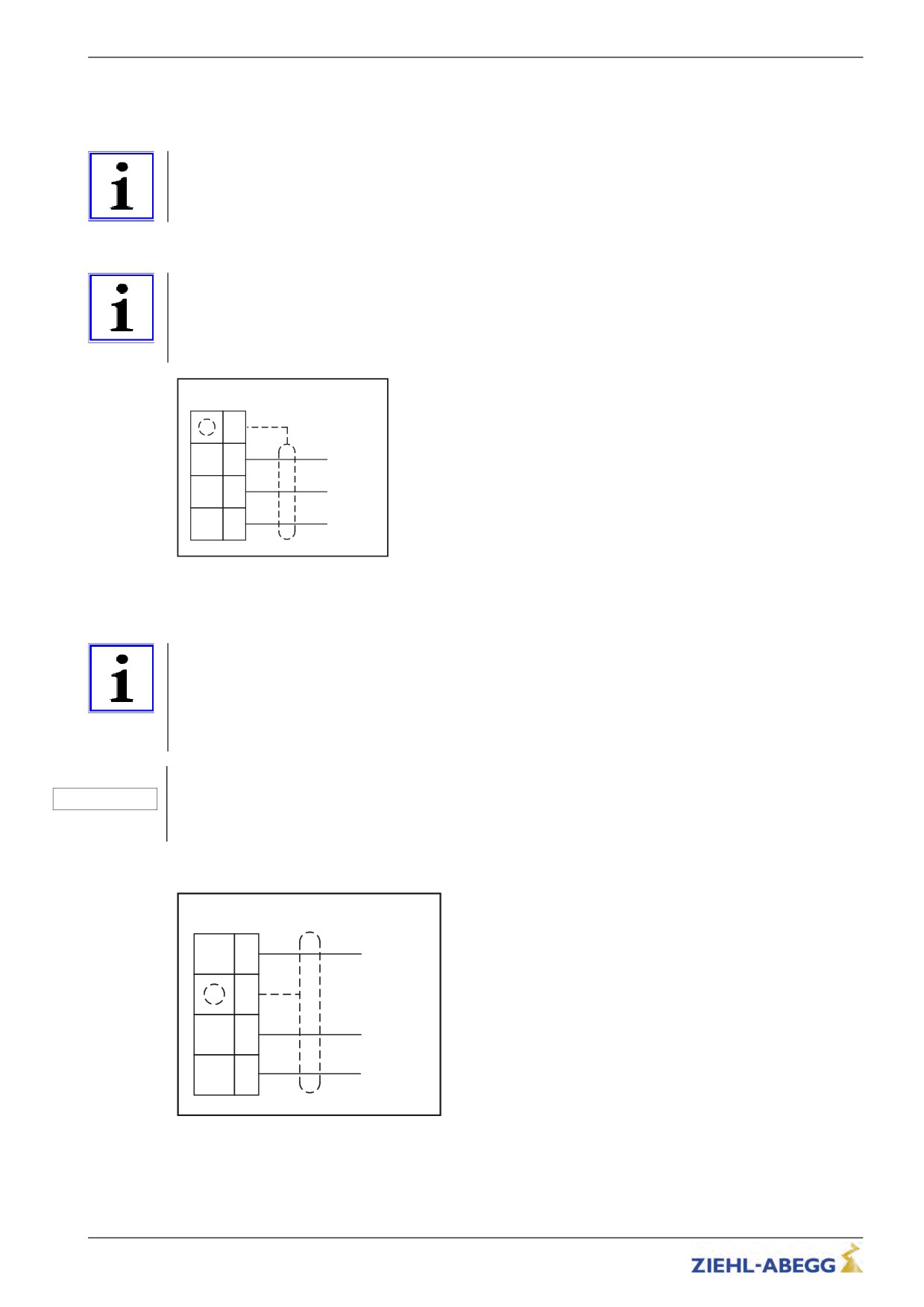
DCP / CAN interface (X-DCP, X-CAN)
Alternatively to the conventional wiring, it is possible to control the frequency inverter by DCP or
CANopenLift (see chapter "Serial Communication").
Information
Operation of the frequency inverter with DCP or CANopenLift is only possible with the add-on module
EM3-CAN-DCP (Art.-No. 357107)!
5.13.1
DCP
Information
• Use a shielded cable for the connection. The shielding must be grounded on the inverter side.
• Make the connection between the frequency inverter and the control system without additional
terminal points.
• The maximum line length is 50 m.
X-DCP
(4)
0VD
(3)
GND
DB
(2)
DATA - (B)
DA
(1)
DATA + (A)
DCP connection
() terminal designation of connector
5.13.2
CANopenLift
Information
• A shielded bus-cable is not needed, but the data wires should be twisted.
• The installation takes place in line structure. The seperate devices are connected to the bus with
short branch lines.
• The bus should be terminated with a terminating resistor of 120 - 150 Ohms, at both ends of the bus.
• The maximum length of the bus is 200 m and 6 m at the branch lines.
Caution!
CAUTION!
Incorrectly wired connections can destroy the electrical / electronic components.
Electrostatic discharges can be hazardous to the electronic components and lead to errors in the
software.
The connection of the bus cable takes place at the slot X-CAN of the frequency inverter.
X-CAN
CH
(4)
CAN High (H)
Optionaler
(3)
Schirmanschluss
CL
(2)
CAN Low (L)
0VC
(1)
GND
Connection CAN
32/200
Electrical installation
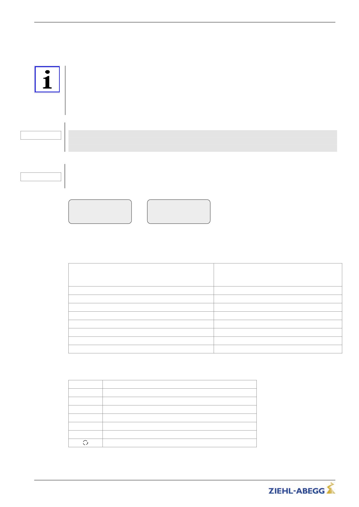
5.14
Encoder connection asynchronous motors (X-ENC8 X-ENC15)
X-ENC9:9-pole SUB-D jack for connection with Sub-D plug
X-ENC15: 15-pole SUB-D jack for connection with Sub-D plug
X-ENC8: 8-pole terminal strip for connection with single wires
Information
When operating the motor with a sinusoidal or incremental encoder, the frequency inverter must be
equipped with the option module EM3-ENC-ASM-ZA (item no. 357104)
• Use a shielded cable for the connection.
• Attach the shielding on the inverter corresponding to the terminal or pin assignments.
• Make the connection between the frequency inverter and the encoder without additional terminal
points.
Caution!
CAUTION!
The SUB-D jack pin assignments are not standardized. When using external encoders, make
sure that they have the identical contact assignments and an interface with identical specifica-
tions.
Caution!
CAUTION!
Before the encoder is plugged on/connected, the encoder type and resolution used must be
configured in the menus "Encoder & BC/ENC_TYP" and "Encoder & BC/ENC_INC " .
Encoder & BC
Encoder & BC
|-" ENC_Typ TTL rect.
|-" ENC_INC 2048
|-"
TTL rect.
|-"
2048
Encoder type
Encoder resolution
5.14.1
Technical data X-ENC8, X-ENC9 and X-ENC15
Encoder types
Sine encoder
Incremental encoder TTL
Incremental encoder HTL (onlyX-ENC8)
Encoder resolution
64 ... 4096 pulse / revolution
Input resistor
120 Ω
Cut-off frequency
200 kHz
TTL differential frequency (against GND)
Ulow <= 0,5 V Uhigh >= 2,5 V
Sine differential signal (at 2.5 V offset against GND)
0,6 Vss ... 1,2 Vss (typ. 1Vss)
Connection cable
Shielded twisted pair cable
Terminal assignment X-ENC8
max. 1,5 mm²
Max. cable length
25 m
5.14.2
Terminal assignment X-ENC8
A
Track A
/A
Track A inverse
B
Track B
/B
Track B inverse
+5V_E
+5 V power supply for sinus and TTL encoder
GND
Ground
+24V_E
+24 V power supply for HTL encoder
Shielding
33/200
Electrical installation
5.14.3
Pin assignment X-ENC9 / X-ENC15
X-ENC9
X-ENC15
1
12
A
Track A
2
7
B
Track B
3
-
-
-
4
4
+5V_E
+5 V power supply for sinus and TTL encoder
5
5
DGND
Ground
6
13
/A
Track A inverse
7
14
/B
Track B inverse
8
-
/FAULT
reserved
9
-
DGND
Ground
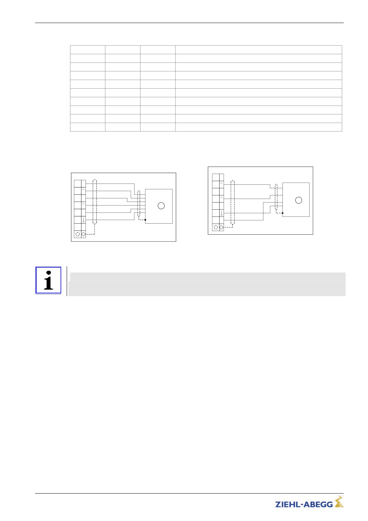
5.14.4
Encoder connection to terminal X-ENC8
TTL incremental encoder (5 V), sine encoder
HTL encoder
(1 Vss)
X-ENC8
X-ENC8
A
A
A
A
/A
A
A
/A
A
B
B
/A
A
B
B
B
/A
/B
B
/B
B
Vcc
1
/B
B
/B
1
5V
5V
0V
Vcc
_E
5V
5V
0V
GND
_E
GND
24V
24
_E
24V
_E
24
HTL encoder connection
1
HTL-encoder
TTL encoder (30V)
1
TTL- or sine encoder
Information
Pay attention to correct connection of the signal tracks when connecting HTL incremental encoders!
• signal A R input /A
• signal B R input /B
34/200
Electrical installation
5.15
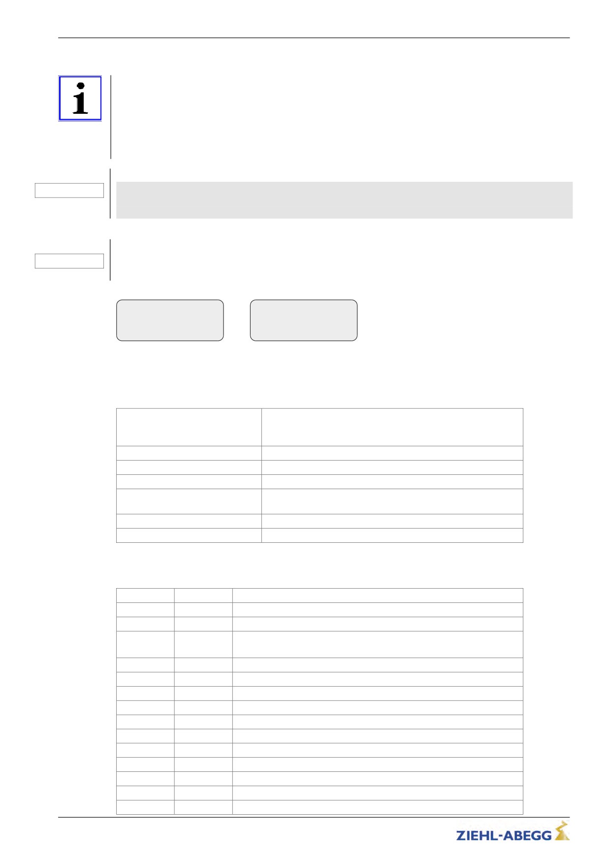
Encoder connection synchronous motors (X-ENC15)
Information
For operating synchronous motors, the frequency inverter must be equipped with the right optional
board to suit the encoder type used!
• Absolute value encoder with EnDat or SSI interface: optional board EM3-ENC-SYN-ZA (art.
no. 357105)
• Absolute value encoder type ERN1387 (not for ZETADYN 3C-MRL): Options board
EM3-ENC-SYN-01 (art. no. 357116)
Caution!
CAUTION!
The pin assignment of the SUB-D-socket X-ENC15 is not standardised. When using encoders
from other manufacturers, make sure that these have the same contact assignment and an
interface with identical specification.
Caution!
CAUTION!
Before the encoder is plugged on/connected, the encoder type and resolution used must be
configured in the menus "Encoder & BC/ENC_TYP" and "Encoder & BC/ENC_INC " .
Encoder & BC
Encoder & BC
|-" ENC_Typ TTL rect.
|-" ENC_INC 2048
|-"
TTL rect.
|-"
2048
Encoder type
Encoder resolution
5.15.1
Technical data X-ENC15
Encoder types
Absolute value encoder with EnDat or SSI interface
Absolute value encoder type ERN1387 (not for ZETADYN 3C-
MRL):
Encoder resolution
512 ... 4096 pulse / revolution
Input resistor
120 Ω
Cut-off frequency
200 kHz
Sine differential signal (at 2.5 V off-
0,6 Vss ... 1,2 Vss (typ. 1Vss)
set against GND)
Connection cable
Shielded twisted pair cable
Max. cable length
25 m
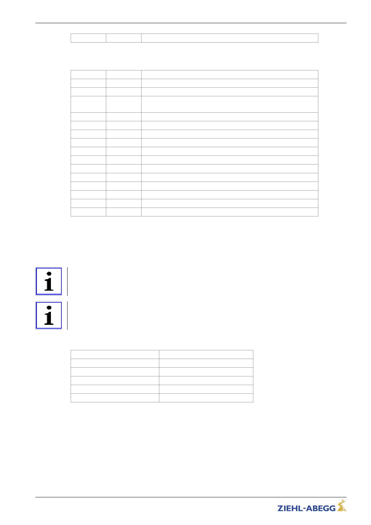
5.15.2
Pin assignment X-ENC15 for absolute value encoder with EnDat/SSI interface
1
DATA
Data line for communication with the absolute encoder
2
/DATA
Data line inverse
3
U+ sens
Sensor cable for encoder voltage (positive)
4
+5V_REG
Controlled +5 V power supply
(With missing encoder the power supply is switched off)
5
DGND
Ground power supply absolute encoder
6
not connected
7
B
Analog track B
8
not connected
9
/CLK
Clock signal invers
10
CLK
Clock signal for serial transfer
11
U- sens
Sensor cable for encoder voltage (negative)
12
A
Analog track A
13
/A
Analog track A inverse
14
/B
Analog track B inverse
15
GND_A_B
Ground for internal shielding
35/200
Electrical installation
Housing
Shielding
5.15.3
Pin assignment X-ENC15 for absolute value encoder type ERN1387 (not for ZETADYN 3C-MRL)
1
not connected
2
not connected
3
U+ sens
Sensor cable - encoder voltage
4
+5V_REG
Controlled +5 V power supply
(With missing encoder the power supply is switched off)
5
DGND
Ground power supply absolute encoder
6
/C
Analog track C inverse
7
B
Analog track B
8
C
Analog track C for transmitting position
9
/D
Analog track D inverse
10
D
Analog track D for transmitting position
11
U- sens
Sensor cable - encoder voltage
12
A
Analog track A
13
/A
Analog track A inverse
14
/B
Analog track B inverse
15
GND_A_B
Ground for internal shielding
Housing
Shielding
5.16
Artificial encoder (X-ENCO)
The encoder simulation transforms the signals of the encoder mounted on the motor into differential
signals according to ANSI standard RS422 um and transmits them to the control. The resolution of the
encoder simulations is identical with the resolution of the encoder.
Information
The X-ENCO connection is not a connection for the impulse encoder but an output for transission of
data to the control. The impulse encoder is connected to connections X-ENC8, X-ENC9 or X-ENC-15.
Information
When connecting an external 24 V voltage source to terminal X-EXT, the artificial encoder remains
active even if the frequency inverter is switched off
5.16.1
Technical data X-ENCO
Output signal high
min. 2,8 V / 8 mA
Output signal low
max. 0,4 V / 4 mA
Rload
≥ 120 Ω
Short-circuit-proof
No
Connection cable
Shielded twisted pair cable
Clamping range
max.1,5mm²
36/200
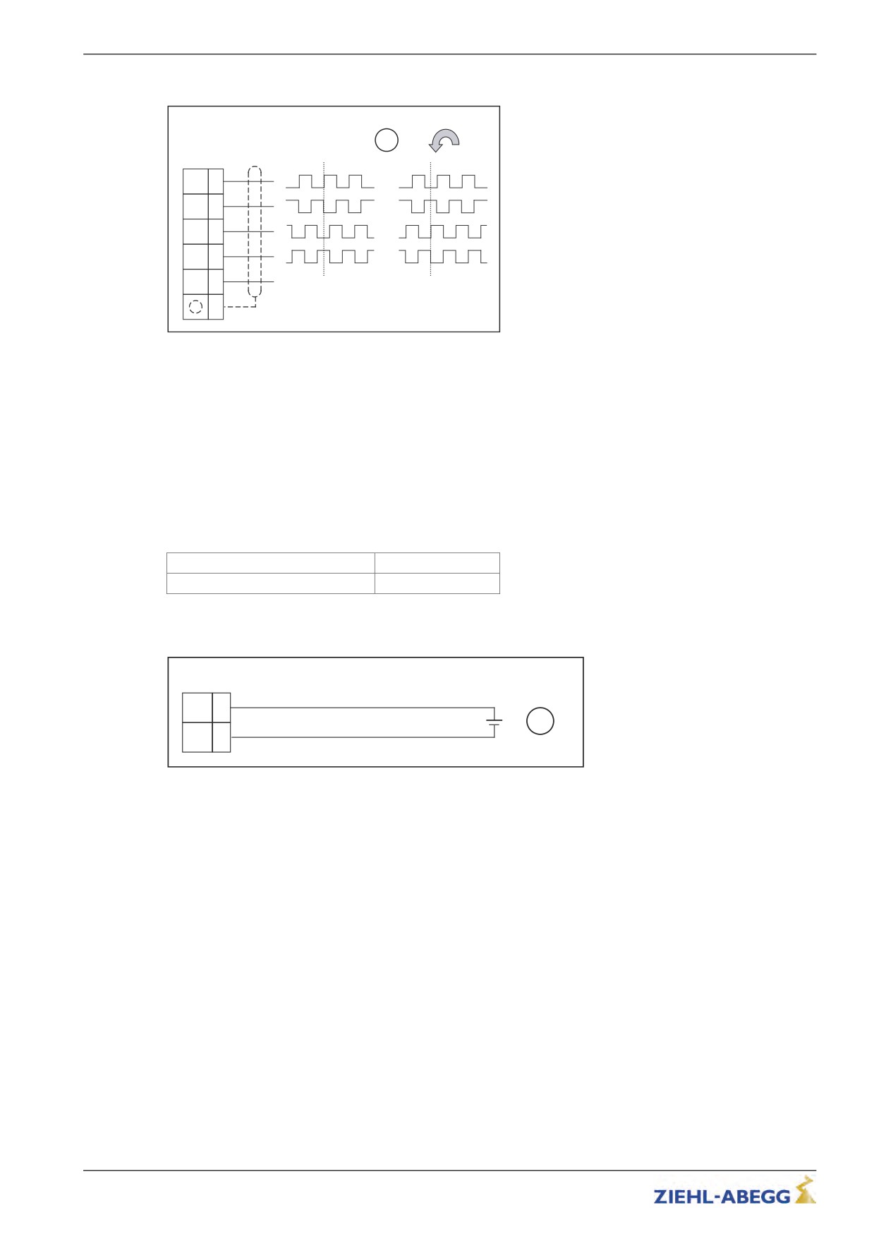
Electrical installation
5.16.2
Connection X-ENCO
1
X-ENCO
X
(6)
/X
(5)
Y
(4)
/Y
(3)
GND
(2)
(1)
Artificial encoder connection
1
Signals depending on the rotating direction of the motor (with view to the power take-off side)
()
terminal designation of connector
5.17
External 24V power supply (X-EXT)
By applying an external 24 V power supply to terminal X-EXT, the following functions are active even
when the frequency inverter is switched off:
• Artificial encoder
• ZETAPAD (parameter changes are possible)
• USB interface of the ZETAPAD
5.17.1
Technical data
Voltage range
23 ... 26 V
Current consumption
max. 625 mA
5.17.2
Connection X-EXT
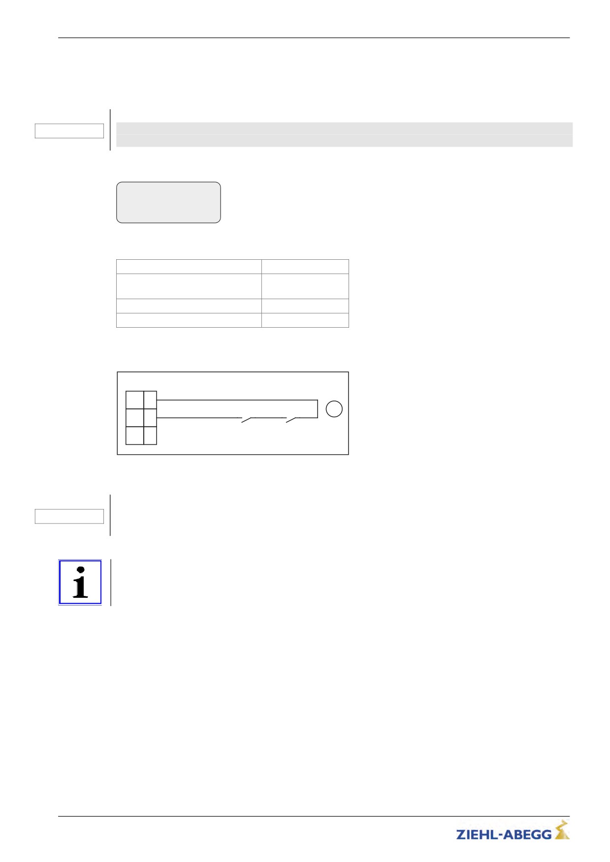
X-EXT
24V
(1)
_EX
+24V
1
GND
0V
(2)
_EX
Connection external power supply
1
external power supply
()
terminal designation of connector
37/200
Electrical installation
5.18
Monitoring the motor contactors(X-CO)
The frequency inverter monitors the switching status of the motor contactors. The contactors must be
applied during travel. Opening the contactors during travel (e.g. through chatter) leads to an immedi-
ate travel abort.
Operating gearless motors is only permissible with connected and activated contactor mon-
CAUTION!
itoring!
The contactor monitoring can be activated/deactivated in the Monitoring/CO menu.
Monitors
|-" CO
Off
|-"
CO1
Contactor monitoring
5.18.1
Technical data
Monitoring voltage
+24 VDC / 12 mA
Contact type
Normally open con-
tact (NO)
Number of inputs
2
Clamping range
max. 1,5 mm²
5.18.2
Connection
X-CO
+24V
(1)
K2
K1
1
CO1
(2)
14
13
14
13
CO2
(3)
Contactor monitoring connection
1
Parameter "Monitoring/CO=CO1"
()
terminal designation of connector
The internal 24V power supply is provided solely for the contactor monitoring. Switching consumer
CAUTION!
load with this voltage is prohibited!
Information
The frequency inverter contactor monitoring does not replace the motor contactors required by EN 81!
38/200
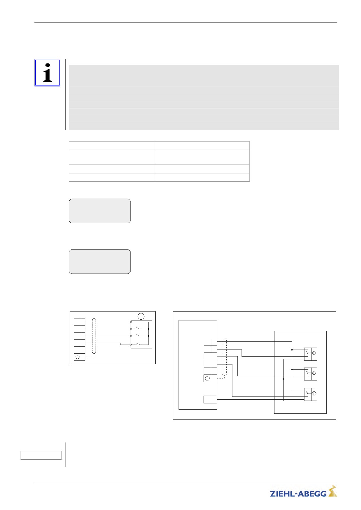
Electrical installation
5.19
Brakes
5.19.1
Brake release monitoring (X-BR)
Information
The brake release monitoring serves as monitoring for redundancy and the operation status of the
brakes.
It is recommended to connect the brake air monitor to the ZETADYN 3 for optimum starting and
stopping.
The monitoring conforms with chapter 9.10 of EN81-1:2010 for brakes as protection for the upside
traveling elevator car against overspeed.
With activated lock function the brake release monitoring fulfills the requirements for self monitoring
according to chapter 9.11.3 of EN81-1:2010 for brake elements for protection against unintendend
movement of the car.
Monitoring voltage
+24 VDC / 12 mA
Contact type
Normally open contact (NO) or nor-
mally closed contact (NC)
Number of inputs
4
Clamping range
max. 1,5 mm²
The contactor monitoring can be activated/deactivated in the menu Monitoring
Monitoring
|-" BR
1*NC
|-"
3*NC
Brake control (BR1..BR4)
The lock function of the ZETADYN is engaged by activating the “LOCKBR=On” parameter in the
menu Monitoring.
Monitoring
|-" LOCKBR Off
|-"
On
Lock inverter
Activation of the parameter ensures that the ZETADYN locks on detection of a faulty brake circuit.
The ZETADYN lock can only be released by setting the “Monitors / UNLOCK = On” parameter.
5.19.2
Connection X-BR
X-BR
1
+24V
(6)
_B
ZETADYN 3
BR1
(5)
BR2
(4)
X-BR
+24V
ZAtop
BR3
(3)
_B
(6)
+
BR4
(2)
BR1
(5)
(1)
BR2
(4)
BR3
(3)
-
+
Connection of brake release monitor with
BR4
(2)
micro switches
1
Monitoring contacts
(1)
-
()
terminal designation of connector
+
X-ENCO
GND
(2)
-
Connection of brake release monitor with initiators
0
terminal designation of connector
Caution!
The internal 24V power supply is provided solely for the brake release monitoring. Switching consumer
CAUTION!
load with this voltage is prohibited!
39/200
//////////////////////////////////////////