ZETADYN 3BF. Operating instruction (Part.-No. 00163264-GB 2/200) - page 5
Special functions
15.2.5
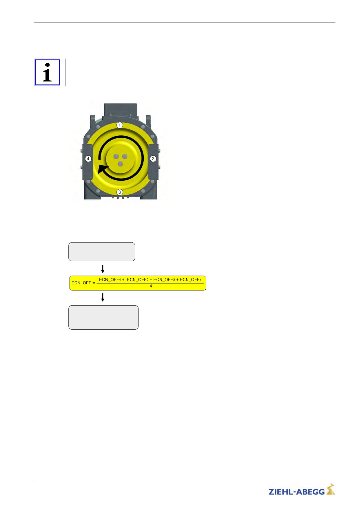
Alignment absolute encoder type ERN1387
The calibration of absolute value encoders of type ERN1387 corresponds to calibration with brake
closed.
Information
To minimize inaccuracies in determination of position, the encoder calibration must be performed 4
times with the brake closed!
The traction sheave needs to be turned through approx. 90° after every calibration.
Positions for the encoder alignment
Carry out encoder calibration type ERN1387
* Result: 2.7A
Perform encoder calibration 4 times with brake closed.
144-228 -> 186/ 6
ENC_OFF= 6 [END]
Note the value for ENC_OFF after each calibration
Calculating the average offset
Encoder-adjust.
|-" ENC_OFF 6.00 DEG
Enter mean offset in parameter "ENC_OFF"
|-"
6.00
in the menu "Encoder-adjust"
Encoder Offset
160/200
Special functions
15.2.6
Error messages during encoder offset alignment
Error no.
Error text
Error cause
01
Drop out of inspect.
Measurement was aborted too soon
Phase current too small
05
Phase UVW is missing
Iu < 200 mA
Iv, Iw < 100 mA
no encoder pulses
06
No encoder impulses
Rotary encoder defective or motor brake is closed
Wrong direction
07
Wrong dir. Check UVW
motor phases are mixed up
Wrong number of pole pairs
08
Wrong amount of pole
Deviation of the increments by ± 10% within one pole
10
Asym. current
Motor current is unsymmetrical
12
Drop out of inspect.
Signals for the inspection trip were removed too early
Brake monitor contacts are active even before the encoder offset
30
BR is not off.
alignment started
Contactor monitor contacts do not switch or contactors are not
40
CO1 does not turn on
open
50
BR does not turn on
Brake monitor contacts do not switch or brakes are not open
52
Input CO interrupt
Contactors open during encoder calibration
Encoder error, absolute value cannot be written into the encoder
60
Adj.cannot be stored
memory
61
Adj.did not store
Encoder error, absolute value not saved in encoder
Brake opens when carrying out an encoder calibration with
70
BR1..4 are activ
closed brake
71
Check nominal power!
Motor data are not correct
161/200
Special functions
15.3
Safety Brake
Function to release the car from the safety gear.
In this function, the motor builds up its maximum torque dependent on the configured values for the
pulse sequence, thus attempting to pull the car from the arrester.
In order to provide the maximum power, the clock frequency of the pulse width modulation is reduced
during the safety-brake function time.
Caution!
Do not repeatedly carry out the safety brake function because that can destroy the frequency
CAUTION!
inverter.
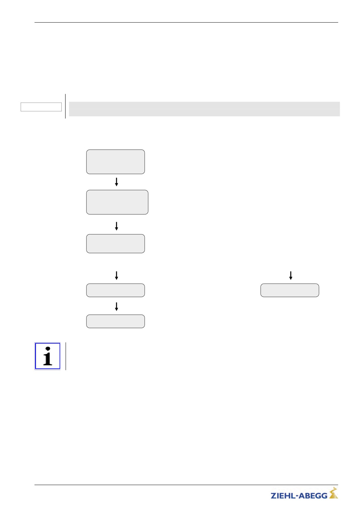
Carrying out the safety brake-function
MMC Recorder
Select "Capture device" menu
->Encoder adjust.
Safety gear
HW-Ident.
Capture device
Select "SB_MOD" parameter
|-" SB_MOD Off
|-"
On
Activate capture release
Freeing function act
Safety Brake
Start capture release by pressing the inspection run push-button
Press inspection!
[esc]
Function successful!
Function faile!
0.0s 4.0A
Stop inspection
Abort inspection run
- - - - - - -> jerk1
in both cases.
SB_INFO 1
[ESC]
Information
If required, the parameters impulse amplitude, impulse time, impulse pause and number of impulses
can be changed in the Capture device menu.
162/200
Special functions
Possible errors during safety gear mode
Error no.
Error description
1
The travelling was interrupted too early by the user.
Travel command has to be longe existent.
2
No absolute encoder existent.
Check encoder connection.
3
No value could be read out of the encoder.
Check encoder cable.
10
Asymetric motor current. Difference over 12.5%.
Check motor phases / contactors.
30
The brake release monitoring reports open brakes although the frequency
inverter did not open them.
Check brake monitoring respectively the brakes.
40
Motor contactors do not switch.
50
Brake does not switch.
71
SIN / COS - Error
72
Missing SSI module
73
Missing SSI dialogue
74
EnDat Light Error
75
EnDat Amplitude Error
76
EnDat Position Error
77
EnDat Supply Error
163/200
Special functions
15.4
Reset
Allocating the parameters of the frequency inverter with a factory setting or customer specific settings.
The works setting is made by a numeric input in the Statistics/RESETmenu.
Reset-functions:
Reset-No.
Effect
preset parametred frequency inverter: Parameters will be set
with customer specific datas
77
Standard frequency inverter: Parameters will be set with
standard data
deleting of:
• Parameter
90
• Error list
• Error messages
Parameters will be set with standard data
deleting of:
• Parameter
•
Error list
99
• Error messages
• Encoder-Offset "ENC_OFF" (will be set to 0)
Parameters will be set with standard data
Caution!
CAUTION!
In synchronous motors, the parameters for the encoder offset (ENC_OFF) are set to 0 during a reset.
If a value was entered beforehand for ENC_OFF, after performing a reset either an encoder-offset
alignment must be carried out or the old values for ENC_OFF must be entered!
Operating the motor without encoder offset alignment can cause uncontrolled motor movements!
Attention! - Reset 90 and 99
Any pre-configuration carried out in the ZIEHL-ABEGG factory is lost when the reset is carried out.
CAUTION!
The parameters are allocated the factory settings. These do not correspond to the pre-config-
uration!
Information
You can only start-up again after entering the parameters in the Motor name plate, Encoder & BC,
Installation, Control system and Monitoring menus (see "Commissioning" chapter).
164/200
Special functions
15.5
Memory card
The following functions are feasible when using a memory card (MMC card or SD card) in the X-MMC
card slot:
• Software-Update (see "Memory card / Software update" chapter)
• Storing parameters (see "Parameter list / Menu Memory Card / Function SAV_PAR" chapters)
• Loading parameters (see "Parameter list / Menu Memory Card / Function LOD_PAR" chapters)
• Storing parameter lists, error lists and parameters with allocation of the frequency inverter serial
number (see "Parameter list / Menu Memory Card / Function SAV_ALL" chapters)
• Continuous recording of operating curves with an MMC recorder and saving the measurements in
standstill (see "Parameter list / Menu MMC recorder" chapter)
15.5.1
Software update
If a software update becomes necessary, you can carry it out using a memory card (SC/MMC).
The update is available at:
• Internet (www.ziehl-abegg.com)
• Email with software from ZIEHL-ABEGG
• Memory card from ZIEHL-ABEGG written with software
Caution!
Carry out a supervised inspection trip after completing the update!
15.5.1.1
Software update with the ZApad operating terminal
Perform a software update
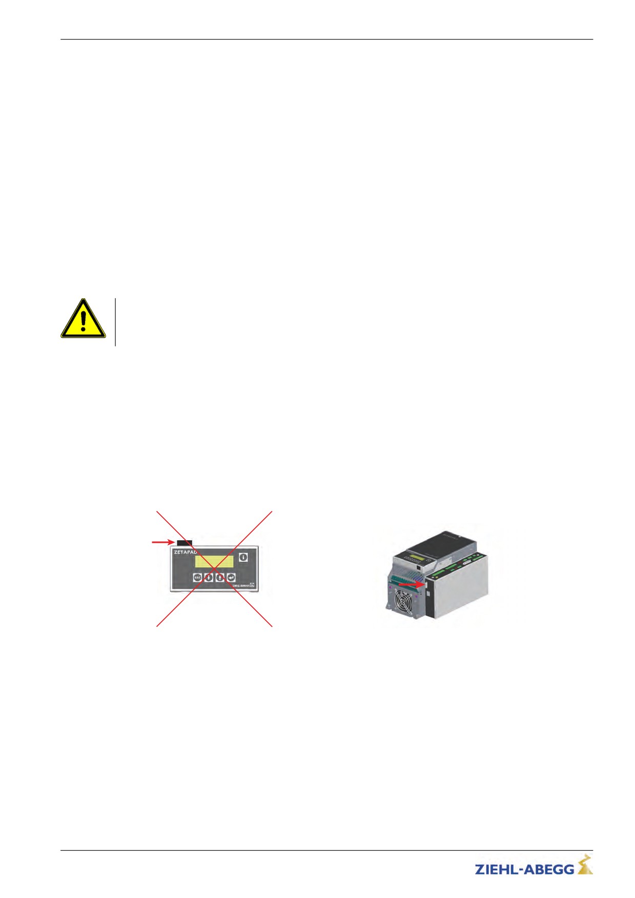
• Insert the memory card in the X-MMC card slot on the controller unit (see figure bottom right).
A software update cannot be made with the card slot on the ZETAPAD! Do not insert the memory
card in the card slot of the ZETAPAD!
✓
Memory card in card slot of the ZETAPAD
Memory card in the X-MMC card slot
165/200
Special functions
Statistics
Select "Memory Card" menu
->Memory Card
MMC Recorder
Confirming menu selection
Encoder-adjust.
Memory Card
Select parameter "UPDATE"
|-" UPDATE
0
|-"
27
Confirming menu selection
Enter "UPDATE=27"
key.
The update is performed and last a maximum 5 minutes.
Please wait ...
max 300s
ZIEHL-ABEGG SE
A restart is performed after the update. The inverter is ready for
ZETADYN 3
SN: 12345678
operation again. The display shown on the left appears.
3.13 - 506
15.5.1.2
Software update without the ZETAPAD operating terminal
" Switch off the master switch and wait until the controller unit is voltage free.
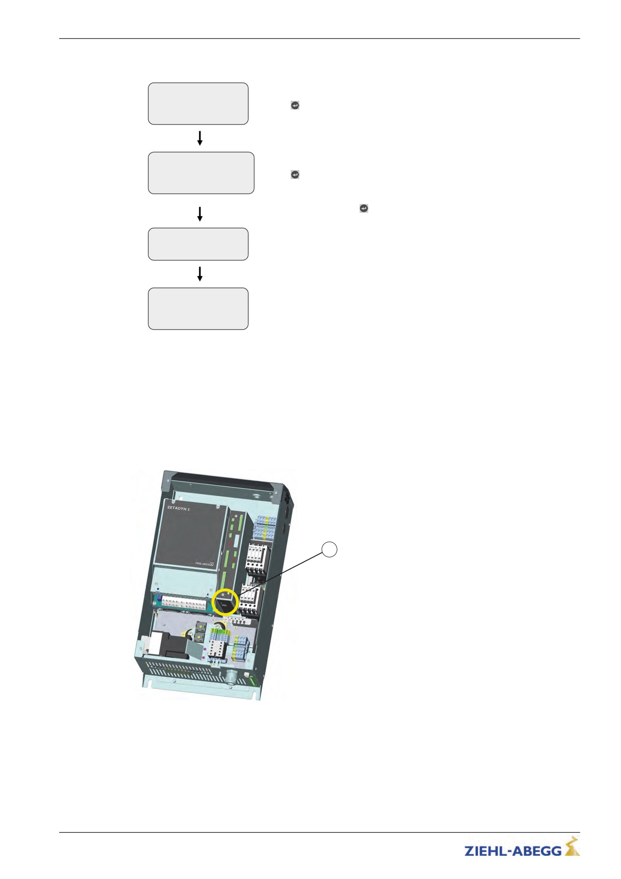
" Insert the memory card with the software update into the "X-MMC" card slot (see Fig.).
" Switch on the master switch. The inverter starts again.
" After the LED "OP1" illuminates for the first time, remove the memory card and then reinsert it. You
must complete this procedure within 5s (watch for fast "OP1" flash code).
✓ The Update starts (duration max. 300s).
Following another automatic reset, the frequency is once more ready for operation.
1
1
X-MMC card slot position
166/200
Special functions
15.5.1.3
Error flash code during a software update
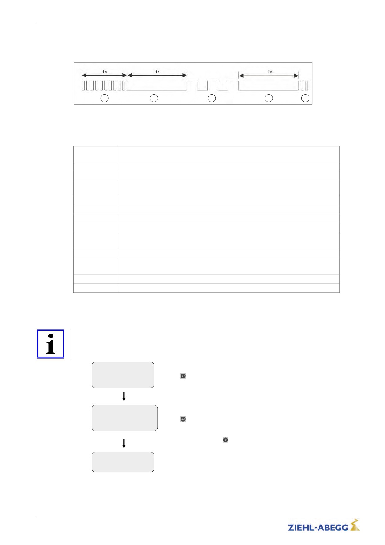
If an error occurs during the software update, a flash code is issued by LED OP1 for the corresponding
error message.
1
2
3
4
5
1
Quickly flashing (10 pulses/s)
2
Break (1 s)
3
Slowly flashing (Number of pulses corresponds to the error message in the table below)
4
Break (s)
5
Cycle is repeated
Number of
Error description
pulses
EEPROM is missing
1
2
The memory card does not contain a software update
The update software on the memory card is identical with the software in the frequency
3
inverter
4
The memory card does not contain a valid software update
5
The files in the update software are identical
6
External application-processor RAM is defective
Internal programing voltage does not switch on
8,14
Internal programing voltage does not switch off
8,19
(it is possible that the prog. key is blocked)
16
Error while deleting the program memory (flash delete error)
Error while writing the program memory (Flash write error)
17
(Flash write error)
18
Error while checking the written files in the program memory (flash data error)
23
Memory card was removed too early
15.5.2
Saving parameters
The parameters of an inverter can be saved on the memory card.
Information
Only the parameters of one inverter can be saved on the memory card. It is not possible to save the
parameters of several inverters.
Statistics
->Memory Card
Select "Memory Card" menu
MMC Recorder
Confirming menu selection
Encoder-adjust.
Memory Card
Select "SAV_PAR" parameter
|-" SAV_PAR OFF
|-"
ON
Confirming menu selection
Select "SAV_PAR=EIN"
key.
The parameters are saved.
Please wait ...
Copy1:_ _ _ _ _ _ _
167/200
Special functions
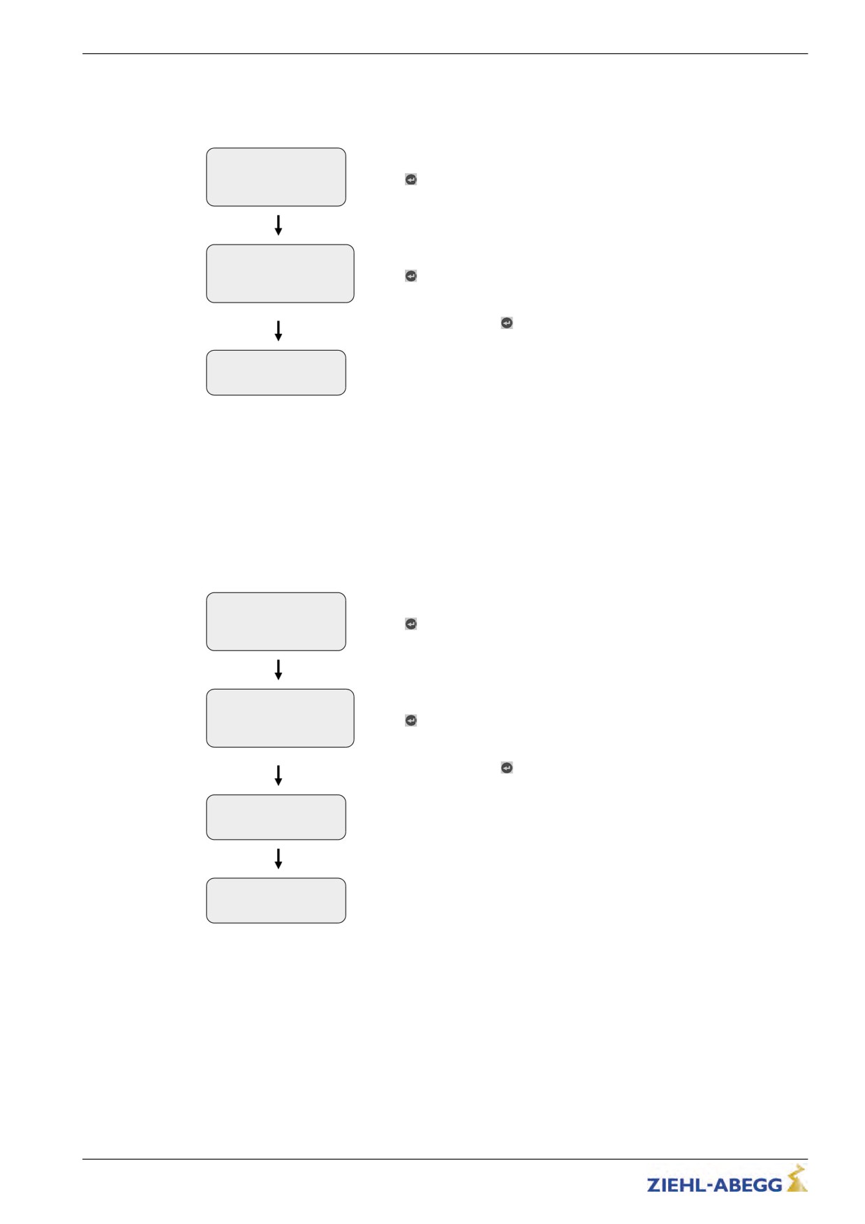
15.5.3
Loading parameters
With identical systems, the saved parameters of an inverter can be loaded into the inverters of the
other systems.
Statistics
->Memory Card
Select "Memory Card" menu
MMC Recorder
Confirming menu selection
Encoder-adjust.
Memory Card
Select "LOD_PAR" parameter
|-" LOD_PAR 0
|-"
27
Confirming menu selection
Enter "LOD_PAR=27"
key.
Please wait ...
The parameters are saved.
Copy1:_ _ _ _ _ _ _
15.5.4
Saving parameters lists, printer lists and error lists
Parameter lists, printer lists and error lists can be saved on the memory card with allocation of the
frequency inverter serial number.
The following folder structure is created on the memory card: "3BF\DEVICE\serial number". The
"LST" and "PAR" folders are created in the "Serial Number" folder. The error lists and printer lists are
saved in the "LST" folder, the parameter lists are saved in the "PAR" folder. The lists are named
according to the actual number of runs at the time of the data backup (e.g. "00000109.FLT" with 109
runs).
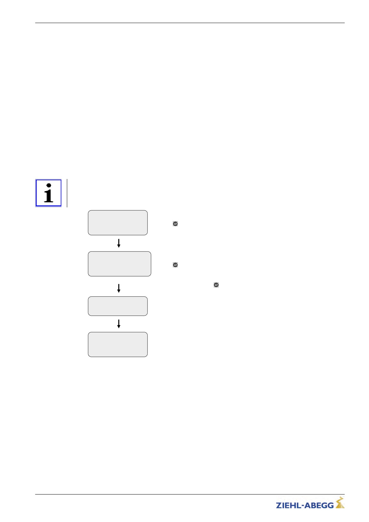
Statistics
Select "Memory Card" menu
->Memory Card
MMC Recorder
Confirming menu selection
Encoder-adjust.
Memory Card
|-" SAV_ALL OFF
Select "SAV_ALL" parameter
|-"
ON
Confirming menu selection
Select "SAV_ALL=EIN"
key.
The parameter list, the printer list and the error list are saved.
Copy1:
_ _ _ _ _ _ _ _ _
Memory Card
-> SAV_ALL Off
After the data backup the "SAV_ALL" parameter reassumes the value
SAV_PAR Off
"OFF".
168/200
Special functions
15.5.5
Performing measurements
It is possible to perform measurements on the frequency inverter. These measurements are config-
ured in the MMC-Recorder menu and can be saved on the memory card. A description of the
individual parameters of the MMC-Recorder menu can be found in the chapter "Parameter List /
Menü MMC-Recorder". The following folder structure is created on the memory card: "3BF\DEVICE\-
serial number\Rec". A sub-folder is created in the "Rec" folder for every measuring variant. The
measurements are saved in these sub-folders. The following sub-folders can be created:
• "ERR"folder: Save measurements which were interrupted by occurrence of an error.
• "NORM"folder: Save measurements for runs without errors.
• "SHOT"folder: Save measurements which were made with the "Stop&Shot" function.
The actual number of runs is used as a file name (e.g. "00000109.ZR3" for 109 runs).
15.5.6
Saving configurations
The configurations of parameters can be saved on the memory card by allocating configuration
numbers. The parameter list and the printer list are saved. The following folder structure is created on
the memory card: "3BF\CONFIG\configuration number". Parameter lists are saved with the file
extension ".PA3" and printer lists with the file extension ".PRT".
Information
If two configurations are saved under the same configuration number, the existing configuration is
overwritten.
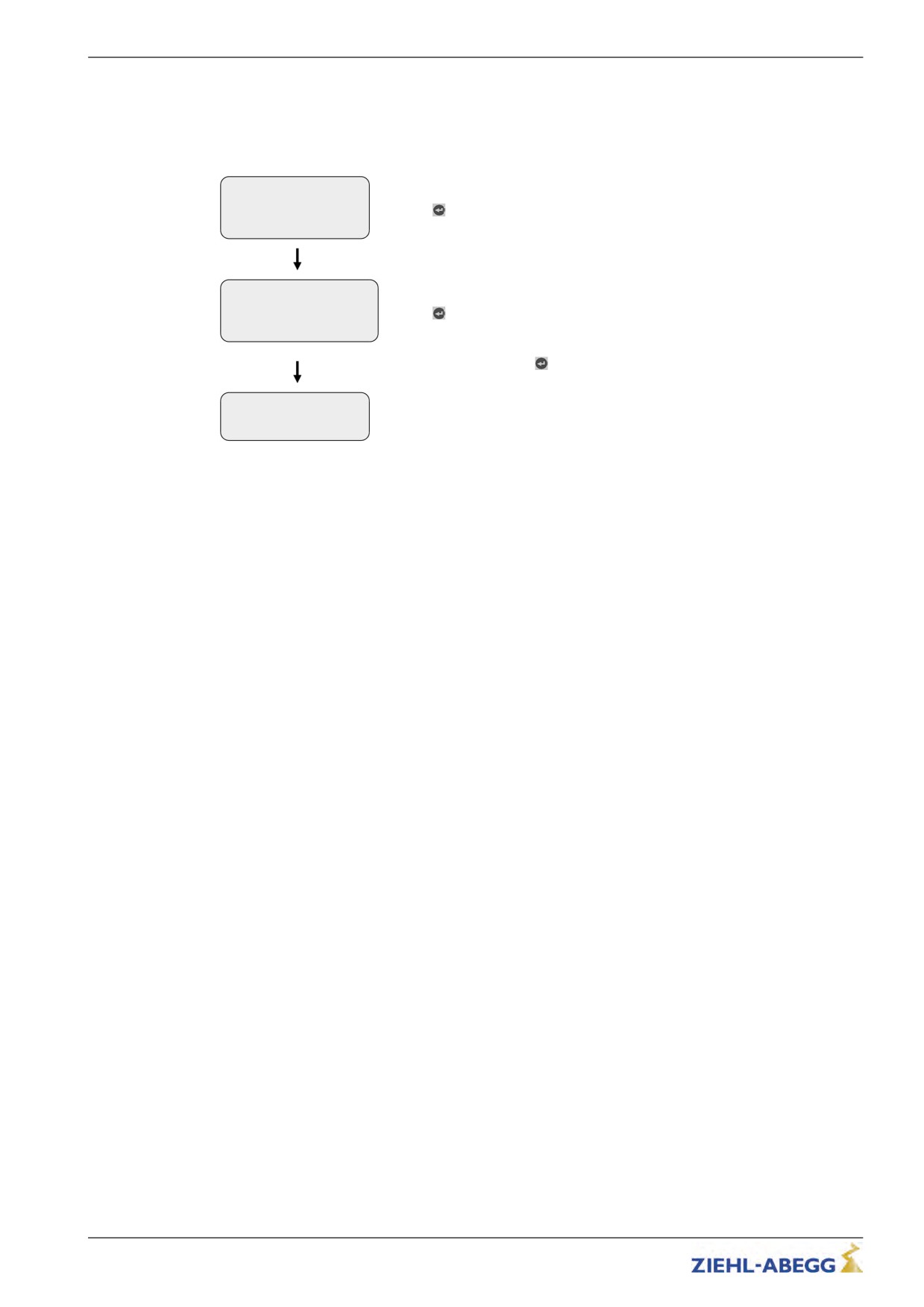
Statistics
Select "Memory Card" menu
->Memory Card
MMC Recorder
Confirming menu selection
Encoder-adjust.
Memory Card
Select "SAV_CFG" parameter
|-" SAV_CFG 0
|-"
1
Confirming menu selection
Line 3: Enter configuration number ("1" in this example)
key.
The parameter list and the printer list are saved.
Copy1:
_ _ _ _ _ _ _ _ _
Memory Card
After the data backup the "Memory Card" menu is displayed again.
UPDATE 0
-> SAV_CFG 0
LOD_CFG 0
169/200
Special functions
15.5.7
Loading configurations
Saved configurations of parameters can be loaded from the memory card into the frequenc inverter by
entering the respective configuration number. The parameters list saved in the "CONFIG" folder is
loaded into the frequency inverter for this.
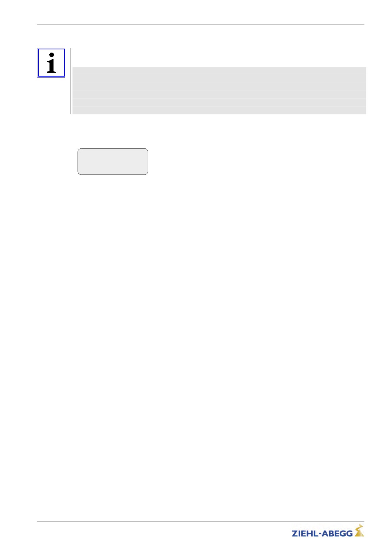
Statistics
->Memory Card
Select "Memory Card" menu
MMC Recorder
Confirming menu selection
Encoder-adjust.
Memory Card
Select "SAV_CFG" parameter
|-" LOD_CFG 0
|-"
1
Confirming menu selection
Line 3: Enter configuration number ("1" in this example)
key.
Please wait ...
The parameter list and the printer list are loaded.
_ _ _ _ _ _ _ _ _
The inverter performs a reset after loading.
170/200
Special functions
15.6
Checking the motor phases
To avoid undefined motor activities due to wrong connection, short circuit , broken wires, etc, the
motor phases will be checked during the start procedure. Therefor the current in the phases U/V/W
will be measured before the brakes are opening.
Due to this monitoring function the starting procedure will be extended by 300 ms.By using the factory
setting "Single" and having correct monitoring result only the first travel after switching-on the inverter
will be extended.
If during the inspection an error is detected the error message E412 - MOT:UVW fail is displayed.
The different monitoring functions can be selected in the menu ZA-Intern/UVW_CHK . The factory
setting is "Single".
Function
Description
Single
Motor phases will be check with the first travel after switching-on the inverter. With a
successful control no more further examination is made.
If the examination is incorrect, with each start an examination is made until a correct
examination could be accomplished.
Cont
Motor phases will be check with each travel
Off
Checking of the motor phases is deactivated
The testing voltage can be selected in the menu ZA-Intern/UVW_PEK an. The factory setting is
"f(P)".
Function
Description
f(P)
The testing voltage depends on the nominal voltage of the motor, which is entered in
the menu "Motor name plate". In case of an error the testing voltage is displayed in
the error message.
1V ... 10V
Selecting the testing voltage between 1 V and 10 V.
In case of an error the testing voltage is displayed in the error message.
15V
Test voltage 15 V.
Error "E412 - MOT:UVW fail" occurs, but the motor connection is correct
If the error "E412 - MOT:UVW fail" occurs even though the motor is connected correct, maybe the
testing voltage is to small. The testing voltage has to be increased manually.
15.7
Field weakening
The operation with field weakening is only possible with asynchronous motor.
If the require motor speed for an asynchronous motor n* is above the rated speed n of the motor, the
ZETADYN 3 automatically switches over to operation in the field weakening range.
In operation with field weakening the magnetizing current I_0 is reduced over the complete speed
range of the motor. The cos phi of the motor data will be increased. Thereby the required speed will be
reached.
The original and the new calculated motor data can be compared in the Info/page05 menu.
171/200
Special functions
15.8
Encoder-less operation (Open-Loop)
Information
Restrictions with Open-Loop-operation:
• no distance dependent deceleration
• no arch-travel
• possibly higher heating of the motor
• worse positioning accuracy than with Closed-Loop-operation
• worse travel confort than with Closed-Loop-operation
• maximum travel speed: 1,0 m/s
15.8.1
Activate operating mode for operation without encoder
To be able to commission a motor without an encoder, the operating mode has to be activated before.
Encoder & BC
|-" ENC_TYP No Enc.
Adjust the parameter "ENC_TYP=No Enc." in the menu "Encoder & BC"
|-"
No Enc.
Encoder type
Further procedure is identical to commissioning for operation with an encoder. This is described in
the section entitled "Commissioning".
172/200
Special functions
15.8.2
Parameter for Open-Loop-operation
For the Open-Loop-operation additional parameters to improve the travel performance are available in
the menu Controller.
The parameters are visible only if operation without an encoder is activated.
If it is necessary to change parameters, the parameter Controller/UF_ED=manually must be
entered.
Factory set-
Parameter
Description
Value range
ting
C_MOD
Controller Mode
Selection of the operation mode of the frequency inverter
FOC
FOC
FOC: Operation with encoder (Closed-Loop)
U/f
U/f: Operation without encoder (Open Loop)
UF_ED
U/f-Edit-mode
On
Enabling the additional parameters with Open-Loop-operation
Off
Off
(U/f)
V_0
Minimum travel speed at start
autom. precon-
0 ... 0.2 m/s
The setpoint for V_0 will be activated before the brake opens
figuration
V_STOP
Minimum travel speed at stop
autom. precon-
0 ... 0.2 m/s
The brake will be closed when the V_STOP is reached
figuration
I_Kipp
Tilting protection: If the entered limit value is exceeded, the set
autom. precon-
0 ... 90 A
value for the speed will be reduced.
figuration
U0
Voltage at speed 0 of the frequence dependent voltage charac-
autom. precon-
0 ... 460 V
teristic
figuration
U1
Start voltage of the frequency dependent voltage characteristic
autom. precon-
0 ... 460 V
figuration
U2
Corner voltage of the frequency dependent voltage character-
autom. precon-
0 ... 460 V
istic
figuration
f1
Start frequency of the frequency dependent voltage character-
autom. precon-
0 ... 125 Hz
istic
figuration
f2
Corner frequency of the frequency dependent voltage character-
autom. precon-
0 ... 125 Hz
istic
figuration
s_FIL
Filter for measuring motor current for the slip compensation
autom. precon-
0 ... 400 ms
figuration
s_COMP
Operation with slip-compensation
On
On:Slip-compensation is activated
Off
Off
Off:Slip-compensation is deactivated
s_LIM
Maximum slip frequency compensation
autom. precon-
figuration
U_S_MX
Maximum output voltage for the slip compensation
0 ... 300 V
80
I_IxR
Current controller, sets the minumm current with wihich the
Nominal cur-
motor is energised
0 ... 90 A
rent (I) of the
motor
I_FIL
Filter of the motor current for the slip-compensation
autom. precon-
0 ... 125 Hz
figuration
IxR_KP
P-contribution of the controller for the current
autom. precon-
0 ... 10 V/A
figuration
IxR_TI
I-contribution of the controller for the current
5 ... 1000 ms
20 ms
IxR_KC
Correction factor of the controller for the current
0 ... 127
0.2
IxR_KD
D-contribution of the controller for the current
0 ... 3.0
0.0
IxR_MX
Maximum limitation of the controller
0 ... 100%
20
IxR_MN
Minimum limitation of the controller
0 ... 100%
0
FADE1
Fading-in and fading-out the current-control and the slip-com-
autom. precon-
pensation depending on the frequency of the rotating field in the
0 ... 125 Hz
figuration
stator
FADE2
Fading-in and fading-out the current-control and the slip-com-
autom. precon-
pensation depending on the frequency of the rotating field in the
0 ... 125 Hz
figuration
stator
173/200
Special functions
15.8.3
Functions with Open-Loop-operation
15.8.3.1
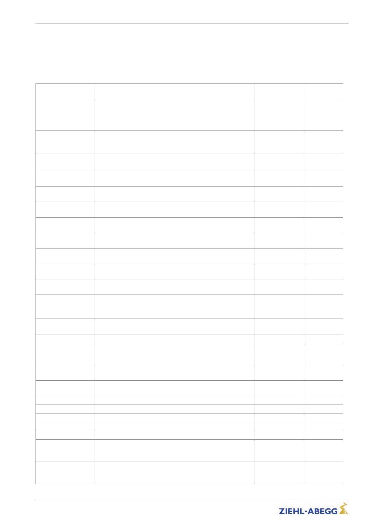
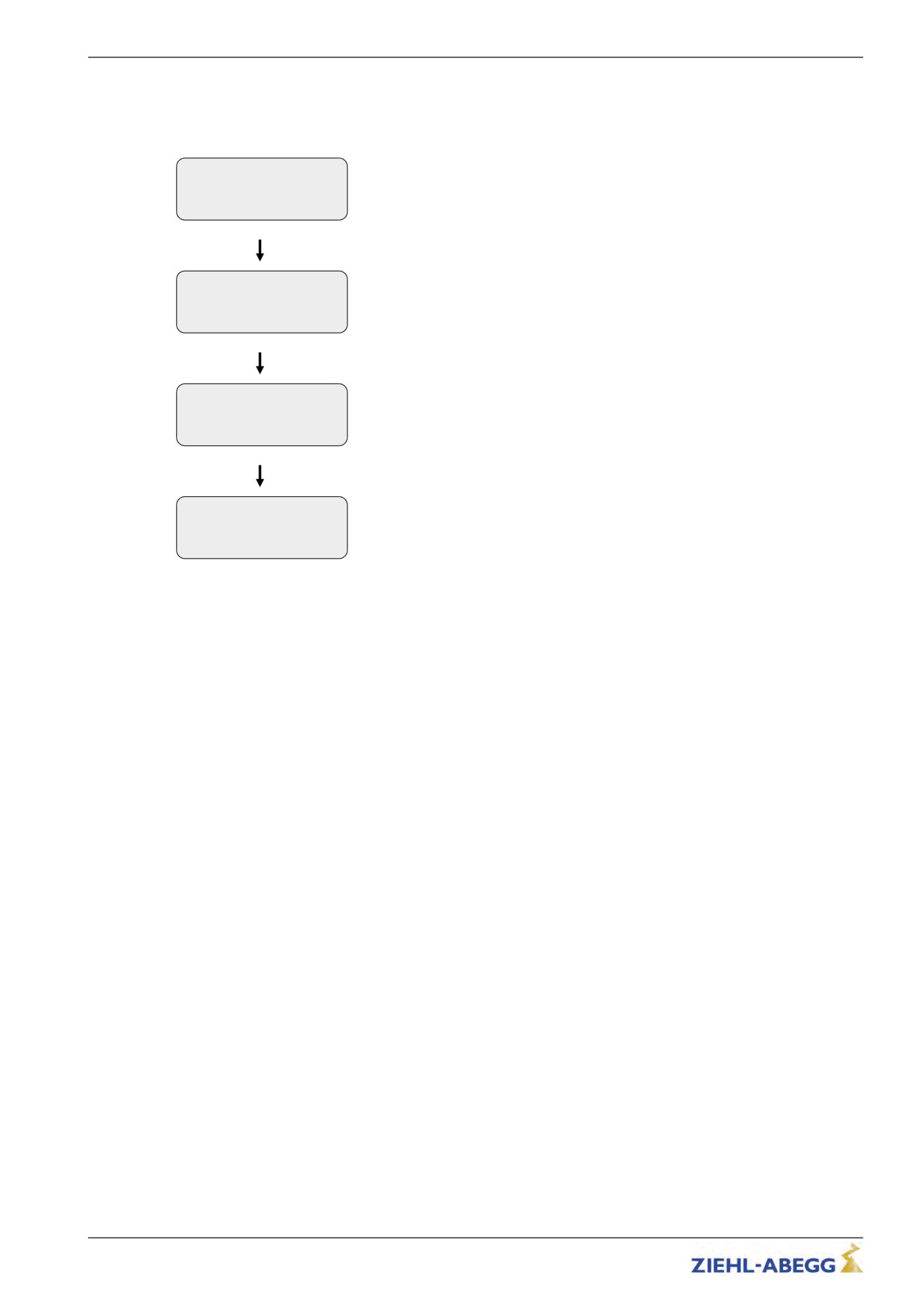
U/f-characteristic curve
With entering the motor data in the menu motor name plate the parameters "U0", "U1", "f1" and "f2"
will be pre-assigned. By these parameters the U/f-characteristic curve will be defined. The U/f-
characteristic curve sets the motor voltage depending on the frequency of the rotating field in the
stator.
U
U2
U0
U1
f1
f1
f
U/f-characteristic curve
15.8.3.2
Current-control
For improving the startin, the stopping as well as the travelling with a slow speed, the motor will be
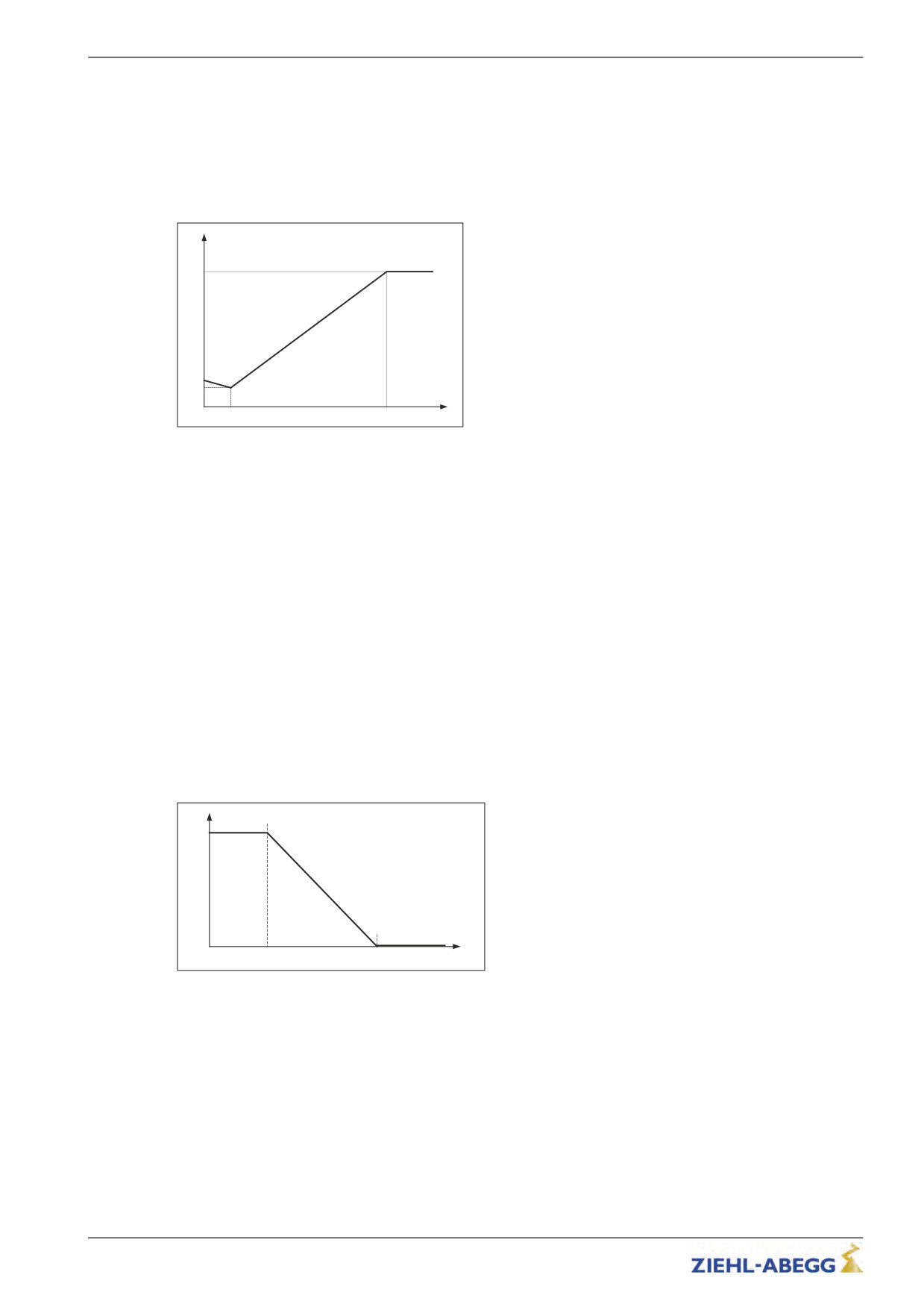
energised with a minimum current (Parameter Controller/I_IxR). With the parameters FADE1 and
FADE2 the current can be set depending on the frequency (f) of the rotating field in the stator.
f < FADE1:
If the frequency of the rotating field in the stator is less than FADE1 the motor will be energised with
100% of I_IxR.
f > FADE2:
If the frequency of the rotating field in the stator is greater than FADE2 the current I_IxR is 0
FADE1 < f < FADE2:
If the frequency of the rotating field is between FADE1 and FADE2 the current-control depends on the
characteristic curve: the higher the frequency the lower is the current impression.
The characteristic curve is defined by the values for FADE1 and FADE2.
100 %
I_IxR
FADE1
FADE2
f
Fader-function for the current-control
15.8.3.3
Slip-compensation
With asynchronous motors the slip (difference between synchronous speed and asynchronous
speed) is proportional to the load of the motor and therefore porportional to the motor current. This
leads to different travel speeds in upwards and downwards direction with the same load.
Example:
The nominal speed of a motor is 1430 rpm. With empty car in downwards direction the speed is
1430 rpm. In upwards direction the speed is 1570 rpm.
The difference of 140 rpm will be settled by the slip-compensation.
174/200
Special functions
The slip-compensation will be activated with the parameter Controller/s_COMP=On.
Control
|-" s_COMP On
|-"
On
U/F: Slip compensation
Functionality:
The motor current is recorded by a filter (parameter "s_FIL"). Proportional to the measured motor
current:
• the slip-frequency will be added or subtracted to the output frequency of the U/f-characteristic curve
• voltage will be added dto the output voltage of the U/f-characteristic curve
The additional values of the slip-compensation will be limited by following parameters:
Control
|-" s_LIM
5
Hz
|-"
5
Frequency: parameter "s_LIM"
U/f:Slip limitation
Control
|-" U_S_MX
80
V
|-"
80
Voltage: parameter "U_S_MX"
U/f:Maximum output
volt.
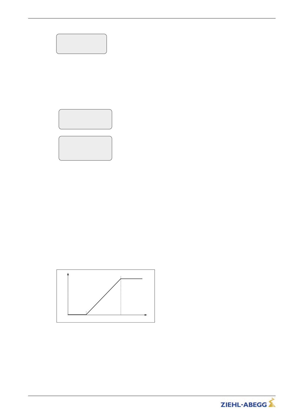
The slip-compensation depends on the paremeter "FADE1" and "FADE2".
f < FADE1:
If the frequency of the rotating field in the stator is less than "FADE1" the slip-compensation is
switched off.
f > FADE2:
If the frequency of the rotating field in the stator is greater than "FADE1" the slip-compensation is
activated 100 %.
FADE1 < f < FADE2
If the frequency of the rotating field in the stator is between "FADE1" and "FADE2" the slip-compensa-
tion depends on the characteristic curve: the higher the frequency the higher the slip-compensation.
The characteristic curve is defined by the values for "FADE1" and "FADE2".
Thereby a seamless transition from current-control to slip compensation and backwards is existing.
100 %
S_COMP
FADE1
FADE2
f
Fader-function with slip-compensation
175/200
Special functions
15.8.3.4
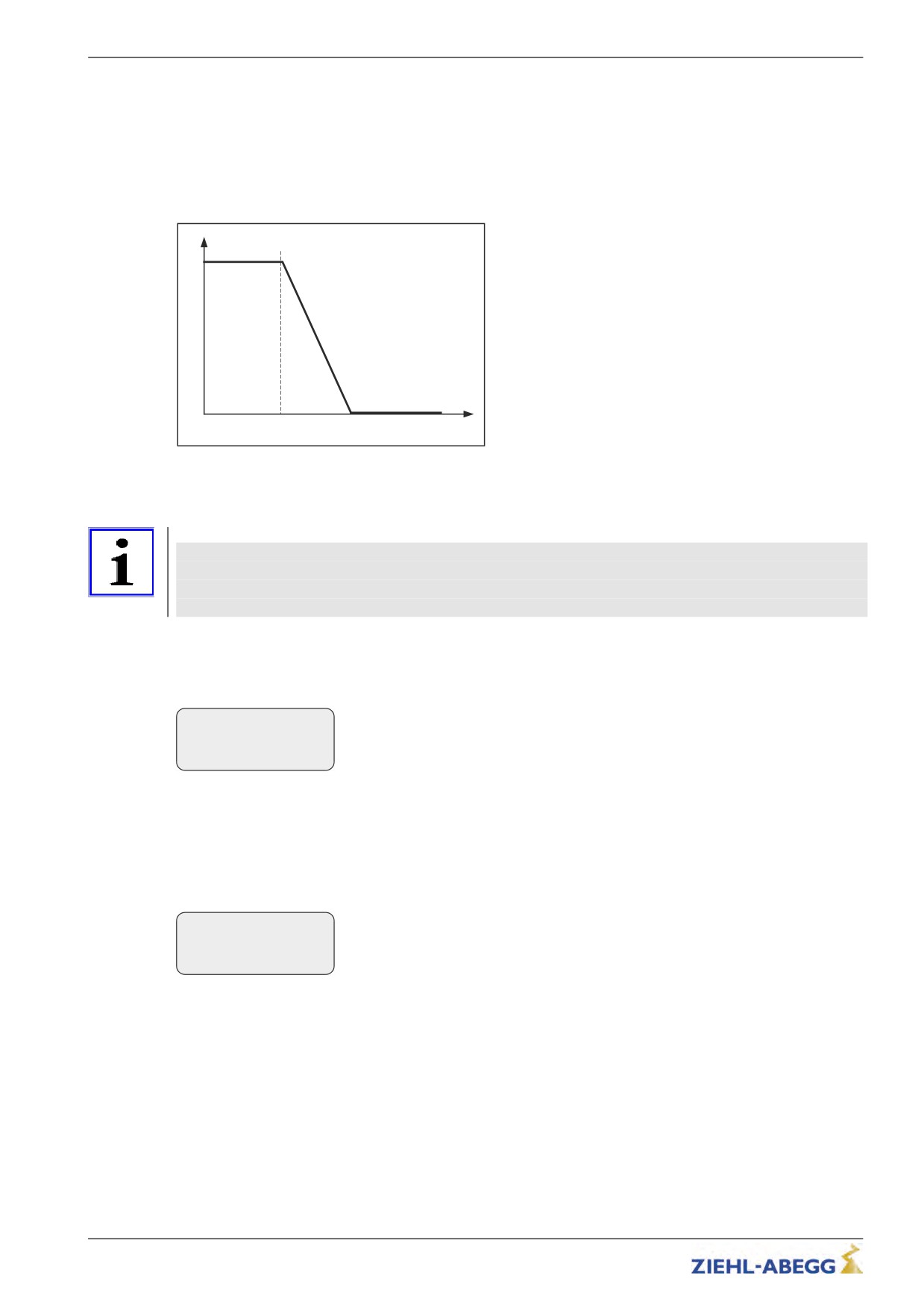
Tilting protection
Avoids an uncontrolled tilting of the speed.
Functionality:
The motor current is recorded by a filter (parameter "s_FIL").
If the setted limit value for the current (Parameter "I_KIPP") is exceeded, the setpoint for the speed
will be reduced linear to the motor current.
f
I_KIPP
I
Tilting protection
15.8.4
Improvements with Open-Loop-operation
Information
The described possibilities for improvements apply only to parameter which are available only in the
U/f-operation mode (Open-Loop).
Possibilities for improving travel curve or the signal-timing are described in the chapter
"Commissioning".
15.8.4.1
Optimizing start up behavior
If the motor has a rollback during the start, the minimum current, which is impressed to the motor, too
low. In this case the parameter Controller/I_IxR must be increased to minimise the rollback.
Control
|-" I_IxR
15
A
|-"
18
15.8.4.2
Slip-compensation
Due to the different speeds in upwards and downwards direction the different positioning travels or
inexactness during the stopping can occur. By having nearly the same speed in both directions these
inaccuracies can be minimised. The adjustment of the speed is carried out by the slip-compensation.
The slip-compensation will be activated with the parameter Controller/s_COMP=On.
Control
|-" s_COMP On
|-"
On
U/F: Slip compensation
176/200
Special functions
15.9
Operation with a 3-phase 230 VAC power supply
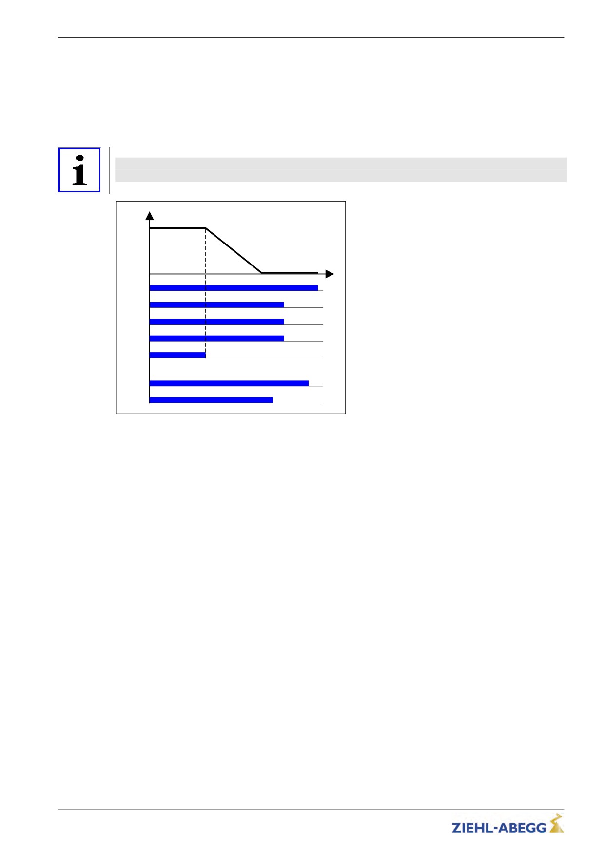
The ZETADYN 3 frequency inverter can be operated with a 3~ 230 VAC power supply.
For this purpose, it is only necessary to adapt various monitoring functions to the lower power supply.
Power component
|-" UDC_N
325
V
|-"
325
In the menu "Power section" configure the parameter "UDC_N=325 V"
Nominal DC voltage
Power component
|-" UDC_MIN 250
V
|-"
250
In the menu "Power section" configure the parameter "UDC_MIN=250 V"
Min. DC voltage
Power component
|-" UDC_MAX 760
V
|-"
760
In the menu "Power section" configure the parameter "UDC_MAX=760 V"
Max. DC voltage
Power component
|-" U_BC
650
V
|-"
650
In the menu "Power section" configure the parameter "U_BC=650 V"
BC intervention voltage
177/200
Special functions
15.10
Controlled emergency stop in inclined elevators
If an emergency stop is implemented in inclined elevators by suddenly closing the brakes, the abrupt
stop can lead to injury to passengers. To avoide this, the cabin should also be braked controlled in
emergency stop.
The /DELAY input function is available for this.
When deactivating the input with the /DELAY function, the motor is delayed with the delay para-
meterised in the Controller/A_MAX menu (see fig.).
Information
At the end of the emergency stop the fault E208 - DELAY active is output.
A new run can only be performed after activating the /DELAY input function!
V
X-IN
t
RF
V1
V3
RV1/RV2
/DELAY
X-OUT
RB
MB
Controlled emergency stop
RF Controller enable
V1
Positioning speed
V3
Travel Speed
RV1 / RV2
Direction default
/DELAY Delay in emergency stop
RB Controller ready
MB_Brake Mechanical brake
178/200
Special functions
15.11
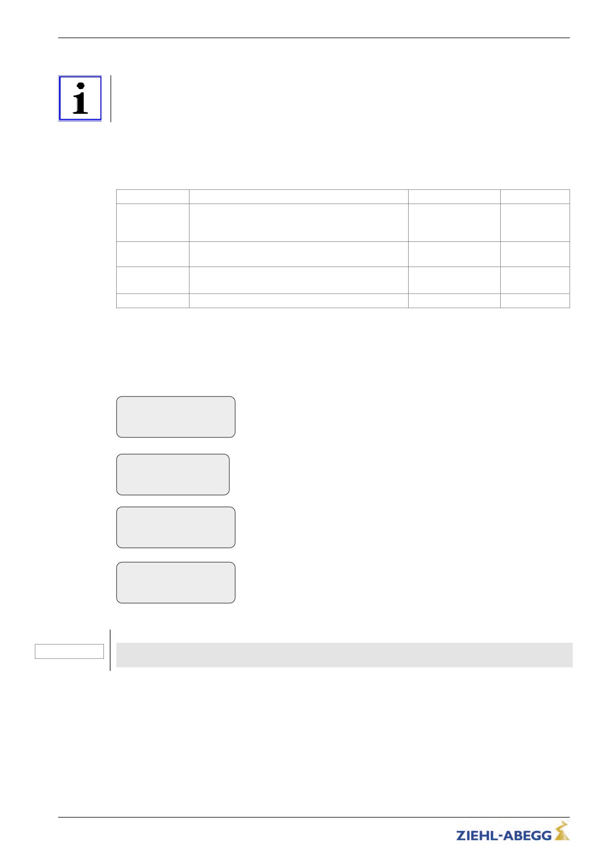
Travel direction counter
Information
The travel direction counter is a down counter which is counting the allowed travel direction changes
with coated ropes. With the travel direction counter the frequency inverter shows an accurately timed
info text when a rope change is necessary.
15.11.1
Parameters for the travel direction counter
For the travel direction counter there are the following parameters, available in the menu Statistic.
In order to be able to use all parameters, the password TD_PWN must be assigned first.
Parameter
Description
Value range
Factory setting
TD_PWN
New password
0 ... 9999
0
A number between 0 and 9999 can be used as a
password
TD_PWC
Displays the password in coded form. If you lose the
nicht einstellbar
21689
password, please contact the manufacturer.
TD_PW
Enter password.
0 ... 9999
0
0 = no password
TD_CNT
Initial value of the down counter
0.00 ... 10.00 M
0.00
The current counter readings and the start value of the direction change counter are also available in
the INFO menu on page 20.
15.11.2
Parametrization of the counter
For using the travel direction counter, the following parameters have to be adjusted.
Statistics
Assign new password with the parameter "TD_PWN" in the menu "Statistic".
|-" TD_PWN
0
|-"
0
If there is already a password existing, you have to enter it to "TD_PW" before it
*New password
can be replaced by a new password.
The coded password is shown with the parameter "TD_PWC" in the menu
Statistics
"Statistic".
TD_PWN 0
With the coded password the ZIEHL-ABEGG SE can decode the original pass-
->TD_PWC 21689
*Encrypted password
word.
For example if the owner has forgotten it.
Statistics
|-" TD_PW
0
Before you can change TD_CNT you have to enter the password to the parame-
|-"
0
ter "TD_PW" in the menu "Statistic".
*Password entry
Statistics
|-" TD_CNT
0
M
Enter the maximum allowed travel directions with the parameter "TD_CNT" in the
|-"
0
menu "Statistic".
*Down counter start value
Caution!
When replacing the ZETADYN 3 the actual value of the down counter "TD_CNT" must be
CAUTION!
transferred to the new ZETADYN 3!
179/200
Special functions
15.11.3
Output functions
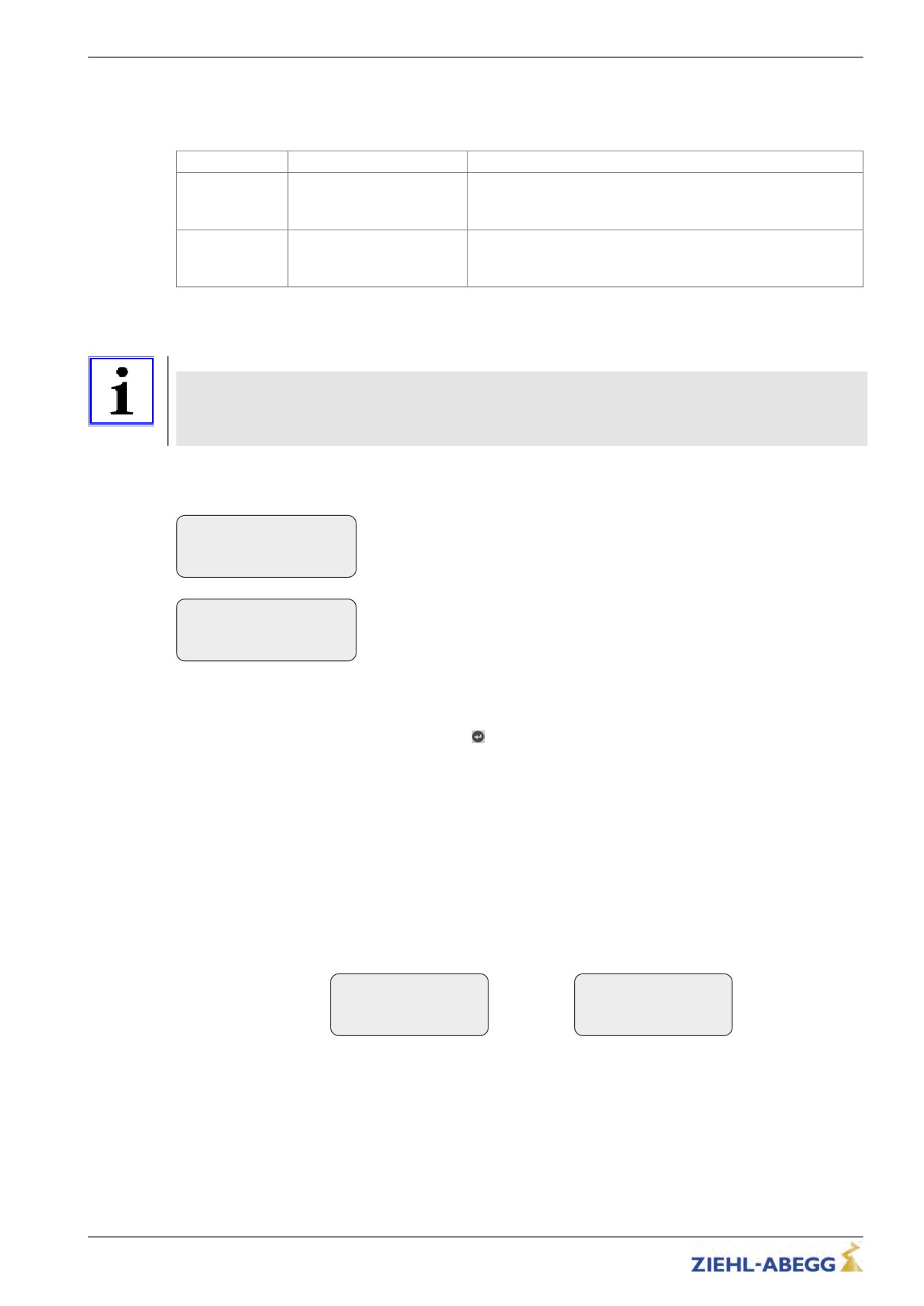
Two special counter functions can be assigned to the digital outputs of the ZETADYN 3 when using
the change of direction counter:
Parameter
Function
Explanation
Info rope
Rope-change necessary
Contact closes when the actual rope still can be used, for approx
1 year.
Contact stays close until the down-counter will be reset.
TD_CNT ext.
Monostable trigger circuit
The output relay gives an impulse to the output at every travel
direction change.
For connecting an external counter, e.g. in the control system
15.11.4
Resetting the travel direction counter
Information
At the end of maximum change of direction ZETADYN 3 is locked and the error "E950 TD_CNT:
Drive Limit" appears in the display.
To move the cabin into the position for a cable change after locking the inverter, ZETADYN 3 must be
switched off and back on. Then a further run is possible.
After a successful cable change, the password must be entered in the Statistics menu and the down
counter set to its new start value:
Statistics
|-" TD_PW
0
Entert he current password in the menu "Statistics", "Parameter" "TD_PW" to
|-"
0
be able reset the value of the down counter.
*Password entry
Statistics
|-" TD_CNT
0
M
Enter the maximum allowed travel directions with the parameter "TD_CNT" in the
|-"
0
menu "Statistic".
*Down counter start value
After successfully setting the down counter the number of counter resets "TD_RES" is increased by
one.
key must be pressed in the INFO menu on page 20.
15.12
Self-monitoring of the brakes according to EN81-A3
The operating brakes can be used as brake elements for protection against unintentional movement
of the car. The micro-switches on the brakes are used for the required self-monitoring. Monitoring can
take place both with normally closed contacts (NC) and normally open contacts (NO). The type of
monitoring contact can be selected in the input programming.
15.12.1
Activation of the self-monitoring
The self-monitoring is activated by selecting the brake circuits count and the function of the micro-
switch based on the “BR” parameter in the “Startup” or “Monitors” menu (e.g. 2 brake circuits with
normally open function of the microswitches: BR=2xNO).
Monitoring
Startup
|-" BR
2*NO
|-" BR
2*NO
|-"
2*NO
|-"
2*NO
Brake Monitoring
Brake Monitoring
180/200
Special functions
15.12.2
Activation of the ZETADYN lock in case of a malfunctioning brake circuit
The lock function of the ZETADYN is engaged by activating the “LOCKBR=On” parameter in the
“Monitors” menu.
Monitoring
|-" LOCKBR Off
|-"
On
Lock inverter
Activation of the parameter ensures that the ZETADYN locks on detection of a faulty brake circuit.
The ZETADYN lock can only be released by setting the “Monitors / UNLOCK = On” parameter.
15.12.3
Function test of the self-monitoring
Function test according to EN81-1:1998+A3:2009
The self-monitoring test required according to EN81-1:1998+A3:2009 Enclosure F8.3.2 is performed
for every software version during internal software tests at ZIEHL-ABEGG.
For this, 10 test runs are made and the function of the self-monitoring checked.
Function test in start-up
If the drive unit brakes are used as brake elements for protection against unintended movement of the
car, a function test of the self-monitoring must be made during start-up.
Test step 1
1. Disconnect signal cable at a monitor input.
2. Perform test run.
3. The error message "380 BR:Start Error" (monitor function "NCC") or "582 BR:T2 too small"
(monitor function "NOC") must be output already at the start, otherwise the monitor is faulty.
4. The ZAdyn locks, no further travel is possible.
5. Re-connect the signal cable.
6. Repeat the test run to check the lock. A new run may not be possible, the ZAdyn is still locked.
7. Release the lock by setting the “Monitoring / UNLOCK = On” parameter (see display).
8. Start new run, this must take place without errors.
Monitors
|-" UNLOCK On
|-"
On
Unlock encoder
Repeat test step 1 for every monitor input.
Test step 2
1. Disconnect the signal cable at a monitor input and short circuit the monitor input with the internal
24V DC voltage source of the ZAdyn.
2. Perform test run.
3. The error message "380 BR:Start Error" (monitor function "NOC") or "582 BR:T2 too small"
(monitor function "NCC") must be output already at the start, otherwise the monitor is faulty.
4. The ZAdyn locks, no further travel is possible.
5. Remove short-circuit and re-connect the signal cable.
6. Repeat the test run to check the lock. A new run may not be possible, the ZAdyn is still locked.
7. Release the lock by setting the “Monitoring / UNLOCK = On” parameter (see display).
8. Start new run, this must take place without errors.
Monitors
|-" UNLOCK On
|-"
On
Unlock encoder
181/200
Enclosure
Repeat test step 2 for every monitor input.
16
Enclosure
16.1
Technical data ZETADYN 3BF
16.1.1
ZETADYN 3BF011 - 032
ZETADYN
3BF011
3BF013
3BF017
3BF023
3BF032
Electrical data
Mains connection voltage
[V]
3~ 180 ... 440 absolut
Mains frequency
[Hz]
50 / 60 (±1,5 Hz)
Network form
TT / TN
Typ. motor output (400 V)
[kW]
4,6
5,5
7,5
11
14
Duty cycle at rated current and clock fre-
[%]
60
quency 8 kHz
Rated current for 60 % duty cycle and
[A]
11
13
17
23
32
switching frequency 8 kHz fixed
Rated current for 60 % duty cycle and
[A]
9
11
15
20
27
switching frequency 12 kHz fixed
Rated current for 60 % duty cycle and
[A]
8
10
13
17
23
switching frequency 16 kHz fixed
Max. operating current (for max. 10s)
[A]
20
24
31
42
58
Power loss at rated current, switching fre-
[W]
97
165
204
288
360
quency 8 kHz and 60 % duty cycle**
Power loss at rated current, switching fre-
[W]
137
225
304
448
570
quency 16 kHz and 60 % duty cycle**
Power losses during standstill
[W]
24
27
Power loss in stand-by 1
[W]
15
15
16
16
17
Power loss in stand-by 2
[W]
11
11
12
12
13
Switching frequency
[kHz]
4 ... 16
Motor frequency
[Hz]
max. 200
Terminal cross-section
[mm2]
6,0
10,0 Hülse
10,0 Hülse
mains / motor
16,0 massiv
10,0 massiv
Min. cable cross-section
[mm2]
-
2,5
2,5
2,5
6,0
Brake-Chopper / Brake-Resistor
Ambient conditions
Protection class
IP20
Ambient conditions operation
[°C]
0 ... 55
from 40°C power reduction of 1.66% / 1K temperature increase
Relative humidity
[%]
90 / condensation prohibited
Installation height
[m
up to 2000
überNN]
from 1000 m power reduction by 1 % per 100 m
Storage and shipping temperature
[°C]
-20 ... +60
Physical data
Weight
[kg]
7,2
10,8
Dimensions h x w x d
[mm]
340 x 195 x 185
340 x 245 x 185
* With a variable clock frequency (menu power section/M_PWM=Auto) a power reduction does not take place.
** including radio interference filter and line reactor
182/200
Enclosure
16.1.2
ZETADYN 3BF040 - 074
ZETADYN
3BF040
3BF050
3BF062
3BF074
Electrical data
Mains connection voltage
[V]
3~ 180 ... 440 absolut
Mains frequency
[Hz]
50 / 60 (±1,5 Hz)
Network form
TT / TN
Typ. motor output (400 V)
[kW]
19,0
24,0
30,0
37,0
Duty cycle at rated current and clock fre-
[%]
60
quency 8 kHz
Rated current for 60 % duty ratio and clock
[A]
50
62
40
74
frequency 8 kHz fix
Rated current for 60 % duty ratio and clock
[A]
42
53
63
34
frequency 12 kHz fix*
Rated current for 60 % duty ratio and clock
[A]
38
46
55
30
frequency 16 kHz fix*
Max. operating current (for max. 3s)
[A]
90
112
134
72
Power loss at rated current, switching fre-
[W]
445
550
650
750
quency 8 kHz and 60 % duty cycle**
Power loss at rated current, switching fre-
[W]
821
675
980
1150
quency 16 kHz and 60 % duty cycle**
Power losses during standstill
[W]
27
32
Power loss in stand-by 1
[W]
17
18
20
21
Power loss in stand-by 2
[W]
13
14
16
17
Switching frequency
[kHz]
4 ... 16
Motor frequency
[Hz]
max. 200
Terminal cross-section
[mm2]
35 inflexible
16,0
mains / motor
25 flexible with cable end sleeve
Min. cable cross-section
[mm2]
6,0
Brake-Chopper / Brake-Resistor
Ambient conditions
Protection class
IP20
Ambient conditions operation
[°C]
0 ... 55
from 40°C power reduction of 1.66% / 1K temperature
increase
Relative humidity
[%]
90 / condensation prohibited
Installation height
[m über
up to 2000
NN]
from 1000 m power reduction by 1 % per 100 m
Storage and shipping temperature
[°C]
-20 ... +60
Physical data
Tightening torque
[Nm]
-
25 mm2=2,5 / 35 mm2=4,5
Weight
[kg]
10,8
23,8
24,6
24,6
Dimensions h x w x d
[mm]
340x245x185
500 x 360 x 190
* With a variable clock frequency (menu power section/M_PWM=Auto) a power reduction does not take place.
183/200
Enclosure
16.1.3
ZETADYN 3BF110 - 180
ZETADYN
3BF180
3BF110
Electrical data
Mains connection voltage
[V]
3~ 180 ... 440 absolut
Mains frequency
[Hz]
50 / 60 (±1,5 Hz)
Network form
TT / TN
Typ. motor output (400 V)
[kW]
55
90
Duty cycle at rated current and clock fre-
[%]
60
quency 8 kHz
Rated current for 60 % duty ratio and clock
[A]
110
180
frequency 8 kHz fix
Rated current for 60 % duty ratio and clock
[A]
110
180
frequency 12 kHz fix*
Rated current for 60 % duty ratio and clock
[A]
93
153
frequency 16 kHz fix*
Max. operating current (for max. 3s)
[A]
198
324
Power loss at rated current, switching fre-
[W]
1116
1860
quency 8 kHz and 35/60 % duty cycle**
Power loss at nominal current, switching
[W]
frequency 16 kHz and duty ratio of
1706
2980
35/60 %**
Power losses during standstill
[W]
73
80
Power loss in stand-by 1
[W]
37
44
Power loss in stand-by 2
[W]
33
40
Switching frequency
[kHz]
4 ... 16
Motor frequency
[Hz]
max. 200
Terminal cross-section
[mm2]
95
mains / motor
Min. cable cross-section
[mm2]
16,0
Brake-Chopper / Brake-Resistor
Ambient conditions
Protection class
IP10
Ambient conditions operation
[°C]
0 ... 55
Relative humidity
[%]
90 / condensation pro-
hibited
Installation height
[m über
up to 2000
NN]
from 1000 m power reduc-
tion by 1 % per 100 m
Storage and shipping temperature
[°C]
-20 ... +60
Physical data
Tightening torque
[Nm]
25 - 30
Weight
[kg]
57,0
63,0
Dimensions h x w x d
[mm]
1050 x 427 x 311
* With a variable clock frequency (menu power section/M_PWM=Auto) a power reduction does not take place.
184/200
EU declaration of conformity
16.2
EU declaration of conformity
- Translation -
(english)
A-KON16_08 1615 Index 001
Manufacturer:
ZIEHL-ABEGG SE
Heinz-Ziehl-Straße
74653 Künzelsau
Germany
The manufacturer is solely responsible for issuance of the EU declaration of conformity.
Product description:
Control devices ZETADYN for elevator machines
Type:
ZETADYN 3BF …
ZETADYN 3C…
ZETADYN 3CA …
ZETADYN 3CS …
(The type details contain further additions concerning the version, e.g. ZETADYN
3BF018-HY)
The above mentioned products of this declaration fulfil all relevant provisions of the following Directives of
the Union:
EMC Directive 2014/30/EU
The following harmonised standards have been used:
EN 12015:2014
Electromagnetic compatibility -
Product family standard for lifts, escalators and moving walks - Emission
EN 12016:2013
Electromagnetic compatibility-
Productfamily standard for lifts, escalators and moving walks - Immunity
This declaration relates exclusively to the product in the state in which it was placed on the market, and excludes
components which are added and/or operations carried out subsequently by the final user.
The authorised representative for the assembly of the technical file is:
Mr. Roland Hoppenstedt (see above for address).
Künzelsau, 20.04.2016
(place and date of issue )
185/200
EU declaration of conformity
ZIEHL-ABEGG SE
ZIEHL-ABEGG SE
Werner Bundscherer
Roland Hoppenstedt
Director Drive Division
Technical Director Drive Division
(name, function)
(name, function)
(signature)
(signature)
186/200
EU declaration of conformity
16.3
Adjustment card
"Motor name plate" menu
Control system menu
Start menu
MOT_TYP
CONFIG
M_START
n
MO_DR
K_START
f
CTRL2)
T_0
p
f_I012)
T_1
I
f_I022)
T_2
U
f_I032)
T_3
P
f_I042)
V_T3
TYP
f_I052)
BRK_DMP
cos phi1)
f_I062)
M_Max
f_I072)
Acceleration menu
f_I08
A_POS
Encoder & BC menu
f_XBR1
R_POS1
ENC_TYP
f_XBR2
R_POS2
ENC_INC
f_XBR3
BC_TYP
f_XBR4
Travelling menu
f_O12)
V_1
Installation menu
f_O22)
V_2
V*
f_O32)
V_3
MOD_n*
f_O42)
V_Z
n*
V_G1
V_4
__D
V_G2
V_5
__iS
V_G3
V_6
__i1
SIM_V12)
V_7
__i2
S_B_OFF
Q
Deceleration menu
F
Monitoring menu
A_NEG
G
MOD_ST
R_NEG1
CO
R_NEG2
BR
S_DI3
LOCKBR
S_DI2
UNLOCK
S_DI1
P1P2
S_ABH
T_ENC
I_MAX
Stop menu
T_I_MAX
T_4
APC
T_5
MASK1
T_5a
MASK2
T_5b
MASK3
T_6
MASK4
MASK5
Controller menu
SPD_KP
SPD_TI
1) The parameter is only visible if "MOT_TYP=ASM" is selected.
2) The parameter is only visible if "CONFIG=00:free" is selected.
187/200
EU declaration of conformity
16.4
Allocation brake resistance, line reactor and radio interference filter
Brake resis-
Radio interference
Inverter
Line reactor
Part no.
tor
filter
BR11-A
-
-
357171
BR17
-
-
357216
ZETADYN 3__011
-
ND011
-
357180
-
-
FEF011KK4D
357192
BR17
-
-
357216
ZETADYN 3__013
-
ND013
-
357181
-
-
FEF023KK4D
357176
BR17
-
-
357216
ZETADYN 3__017
-
ND017
-
357182
-
-
FEF023KK4D
357176
BR25
-
-
357217
ZETADYN 3__023
-
ND023
-
357183
-
-
FEF023KK4D
357176
BR25
-
-
357217
BR50
-
-
357218
ZETADYN 3__032
-
ND032
-
357184
-
-
FEF040KK4D
357177
BR50
-
-
357218
ZETADYN 3__040
-
ND040
-
357185
-
-
FEF040KK4D
357177
BR50
-
-
357218
ZETADYN 3__050
-
ND050
-
357186
-
-
FEF050KK4D
357178
BR50
-
-
357218
ZETADYN 3__062
-
ND062
-
357187
-
-
FEF074KK4D
357179
BR50
-
-
357218
BR100-A
-
-
357214
ZETADYN 3__074
-
ND074
-
357188
-
-
FEF074KK4D
357179
BR100-B
-
-
357215
ZETADYN 3__110
-
ND110
-
357196
-
-
FEF180KK4D
357199
BR100-B
-
-
357215
ZETADYN 3__180
-
ND180
-
357197
-
-
FEF180KK4D
357199
188/200
EU declaration of conformity
16.5
Type designation
ZETADYN
3
xx
0xx
-1
Series
3rd generation
Structure
BF
Basis unit for synchronous and asynchronous motors
not including line reactor, radio interference filter and motor contac-
tors
CA
Complete unit for asynchronous motors
Including power choke, filter and motor contactors and brake contac-
tors (optional)
CS
Complete unit for synchronous motors
Including power choke, filter and motor contactors and brake contac-
tors (optional)
Rated current
009
9 A
011
11 A
013
13 A
017
17 A
018 (HY)
18 A
023
23 A
025 (HY)
25 A
032
32 A
040
40 A
050
50 A
062
62 A
063 (HY)
63 A
074
74 A
080 (HY)
80 A
105 (HY)
105 A
110
110 A
180
180 A
Additional designation
1
Operating voltage 230 VAC
MRL A
with expansion module and integrated brake resistor
MRL BI
without expansion module, with integrated brake resistor
MRL BE
without expansion module, with external brake resistor
HY
for hydraulic elevators
189/200
EU declaration of conformity
16.6
Part no.
Inverter
Part no.
ZETADYN 3BF009-1
352190
ZETADYN 3BF011
352170
ZETADYN 3BF013
352171
ZETADYN 3BF017
352172
ZETADYN 3BF023
352173
ZETADYN 3BF032
352169
ZETADYN 3BF040
352178
ZETADYN 3BF050
352179
ZETADYN 3BF062
352176
ZETADYN 3BF074
352177
ZETADYN 3BF110
352191
ZETADYN 3BF180
352192
190/200