8 WHEELER DIESEL ELECRIC TOWER CAR WITH UNDERSLUNG TRANSMISSION. OPERATING & MAINTENANCE MANUAL (2019) - page 4

TRACTION MOTOR
INSPECTION INTERVAL
TRIP
MONT
THRE
SIX
YEARL
TWO
REPAIR
HLY
E
MONT
Y
YEARL
INSPECTION ITEMS AND
LIMIT OR
MONT
HLY
Y
STANDARD
OPERATIO
HLY
N RANGE
h. Interference fit shall be applied
0
to inlay of pinion.
Interference Heating temperature :
140 - 160º C above ambient
i. Contact degree of armature shaft
80
%
0
and taper of pinion shall be more
minimum for
than 90 %
used
0
j. Ultra sonic and magnetic particle
testing shall be carried out about
shaft.
3. STATOR
3.1 Magnet frame
0
a. Dimensions of mounting parts
(as shown in drawing)
b. Lead wire with damaged
covering or damaged terminal shall
be replaced.
Less than
10
c. Damage of core of lead wire and
%
connector may be used
0
3.3 Brush holder and Carbon Brush
0
0
0
a. Cleaning and check
b. Spring pressure (at assembly) at
2.50 to
3.30
0
0
0
At Brush height 57 mm : 3.20 kgf
kgf/brush
/brush
At Brush height 32 mm : 2.80 kgf/
brush
c. Dimensions of brush holder
0
0
pocket
20.3 mm
Thickness : 20.00 mm
Width : 40.00 mm
40.3 mm
MAINTENANCE MANUAL FOR DETC-US

TRACTION MOTOR
INSPECTION INTERVAL
TRIP
MONT
THRE
SIX
YEARL
TWO
REPAIR
HLY
E
MONT
Y
YEARL
INSPECTION ITEMS AND
LIMIT OR
MONT
HLY
Y
STANDARD
OPERATIO
HLY
N RANGE
d. Clearance between Brush holder
0
0
Face and commutator surface
Gap : 2 - 3 mm nominal
Distance between brush end face
0
and commutator end face : more
0
0
0
0
than 4 mm
Service length
e. Length of carbon brush
: 25 mm
Exchange
f. Chipping of carbon brush
limit : 32 mm
0
0
0
0
0
g. Pigtail breaking of brush
less than 10 %
0
0
0
0
0
3.4 Gear Case
0
a. Check the gear compound level
0
0
0
0
b. Check the packing of gear case.
0
Worn packing should be replaced.
c. Gear compound leakage
0
0
0
0
0
4.
ASSEMBLY TEST AND
OTHERS
a. Bedding of carbon brush
0
0
0
0
b. Dielectric test
New
: 2.5 kV, 50 hz for 1 min
1.5 KV/1min
Repaired : 1.5 kV, 50 hz for 1 min
(Repaired)
0
c. Insulation Resistance test
d. No - load test
Examine abnormal vibration or
More than 1.0
0
0
abnormal noise
MΩ
i.
1000 rpm for 1 hour in both
0
directions.
ii.
2000 rpm for 15 min in both
directions.
MAINTENANCE MANUAL FOR DETC-US
TRACTION MOTOR
NOTES
----------------------------------------------------------------------------------------------------------------------------------------
----------------------------------------------------------------------------------------------------------------------------------------
----------------------------------------------------------------------------------------------------------------------------------------
----------------------------------------------------------------------------------------------------------------------------------------
----------------------------------------------------------------------------------------------------------------------------------------
----------------------------------------------------------------------------------------------------------------------------------------
----------------------------------------------------------------------------------------------------------------------------------------
----------------------------------------------------------------------------------------------------------------------------------------
----------------------------------------------------------------------------------------------------------------------------------------
----------------------------------------------------------------------------------------------------------------------------------------
----------------------------------------------------------------------------------------------------------------------------------------
----------------------------------------------------------------------------------------------------------------------------------------
----------------------------------------------------------------------------------------------------------------------------------------
----------------------------------------------------------------------------------------------------------------------------------------
---------------------------------------------------------------------------------------------------------------------------------------
MAINTENANCE MANUAL FOR DETC-US
CHAPTER VIII
AUXILIARY ALTERNATOR
1. INTRODUCTION
2. DESCRIPTION
3. PRINCIPLE OF OPERATION
4. WORKING OF REGULATOR
5. ROUTINE MAINTENANCE
6. PERIODICAL OVERHAULING
7. REMOVAL OF ROTOR & BEARINGS
8. ASSEMBLY
9. DO’s AND DON’Ts
Maintenance Manual
DIESEL ELECTRIC TOWER CAR | UNDER SLUNG TRANSMISSION
AUXILIARY ALTERNATOR
CHAPTER VIII
AUXILIARY ALTERNATOR
1. INTRODUCTION
KEL Alternators type KELA 121125 FM are designed to be driven with a cardan shaft coupled directly to the
diesel engine through flexible coupling. The alternator with associated regulator rectifier unit delivers 8 KW
power at a constant voltage of 120 ± 5% from no load to 74 A load at all notch positions of the engine.
The system consists of a Brushless inductor type alternator and a completely static regulator rectifier unit.
The alternator is completely devoid of any type of moving coils or sliding contacts and this ensures a trouble
free operation without practically any maintenance.
The regulator - rectifier unit makes use of silicone diodes, and “Magnetic Amplifiers”. All the components
used in the rectifier - regulator unit are unlike transistors and thyristors-tailor made to the requirements of the
hazardous application to which they are put in Rolling stock. As such the reliability of KEL generating
system is high.
2. DESCRIPTION:
The statodyne type KELA 12125 FM is a totally enclosed machine developing a constant voltage of 120V (
±5% ) at a maximum load current of 74 Amps DC.
The machines are used for :
I.
Charging of 110 Volts battery provided on the car.
II.
Light and fan loads of the coach
III.
Control system (20 Amps)
IV.
Head light of 750 watts at 32 volts, the voltage being dropped through a resistor from 135 volts
DC.
MAINTENANCE MANUAL FOR DETC-US
AUXILIARY ALTERNATOR
2.1 Generator data
Rated Capacity
:
8 KW
Type
:
KELA 12125 FM
Mounting
:
Foot Mounting
Enclosure
:
Totally Enclosed IP 55
Cooling
:
Self cooled
Minimum speed for full output
:
700 rpm for 70A at 120 Volts.
Maximum speed
:
2000 rpm
Weight of Alternator
:
302 Kg
Class of insulation :
a) Stator
:
Class H
b) Field
:
Class H
Type of Bearing :
a) Drive End
:
NU311
b) Non drive End
:
6311
Resistance between two phase
:
0.198 Ohms ± 5%
Field Resistance
:
12.98 Ohms ± 5%
2.2 Rectifier-Regulator Unit :
Type
:
KEL C 12125 FM
Full load
:
64 A
Voltage setting
:
125 V at 32 A at 1500 rpm
Max load
:
74 A
Class of insulation
:
F
Weight of Regulator
:
52 Kg
The rectifier regulator also is a totally enclosed unit. It consists of:
i.
A power rectifier comprising of :-
a. One full wave, three phase bridge connected rectifier, using six silicone diodes.
b. Capacitors to protect the rectifier diodes from surges and to filter the DC output.
ii. A regulator rack consisting of :-
a. One field transformer
( FT )
MAINTENANCE MANUAL FOR DETC-US
AUXILIARY ALTERNATOR
b. One magnetic amplifier
( MA )
c. One Field rectifier unit
( D3, D4 )
d. Two voltage detectors
( DT1 & DT2 )
e. One free wheeling diode
( D5 )
f.
One burden resistance
( RBI )
g. Two blocking diodes
( D1, D2 )
iii. Three current transformers connected in star for sensing the load current
(CT1,
CT2 &
CT3)
The phase and field fuses are provided on the rectifier board of the regulator.
The labels provided for terminals on the terminating portion of the regulator as follows.
U, V, W
-
AC input to Regulator from Alternator.
+DC, -DC
-
DC output from regulator
Output field terminals from regulator to alternator field coil terminals.
3. PRINCIPLE OF OPERATION
3.1Generator
As mentioned above the statodyne generator is a three phase, homopolar, inductor type alternator without any
rotating, commutator or sliprings. The field windings and AC windings are located in the stator. The field
coils are concentrated in two slots.
Each field coil shares half the total number of stator
slots.
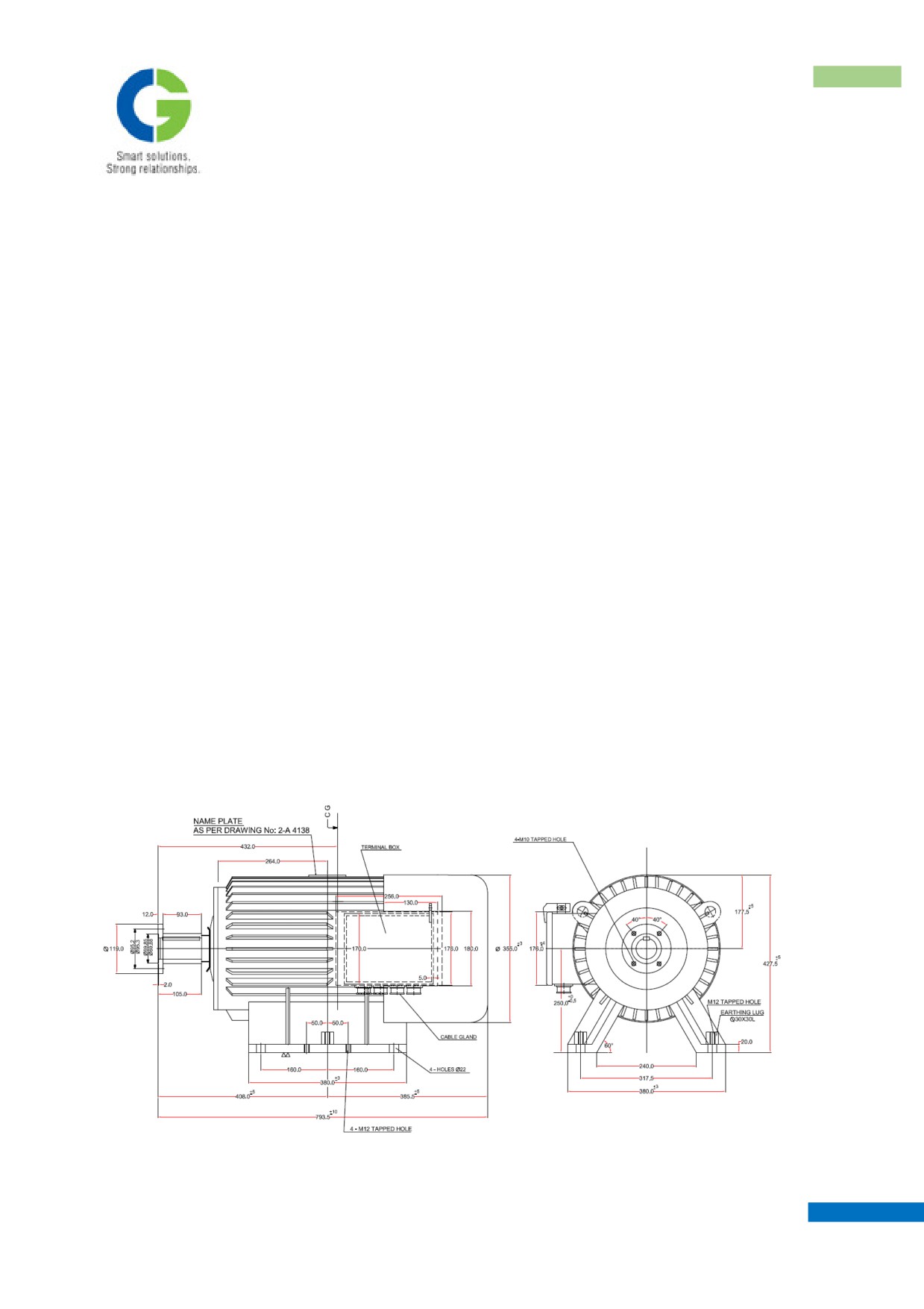
Outline drawing of 8 kW Auxiliary alternator
MAINTENANCE MANUAL FOR DETC-US
AUXILIARY ALTERNATOR
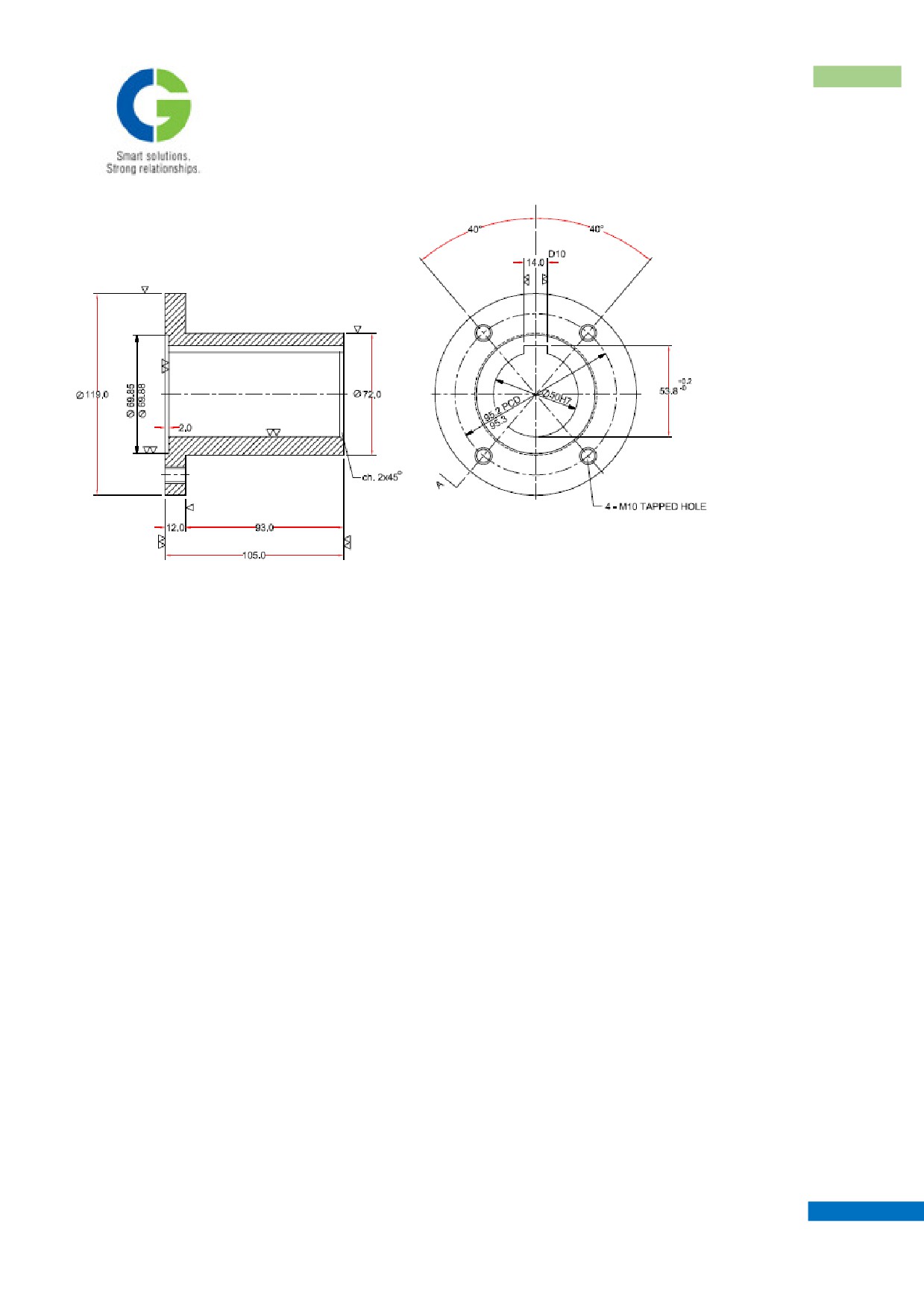
Details of Coupling Flange
The rotor is made up of silicon steel laminations and resembles a cogged wheel. The teeth and slots are
uniformly distributed on the rotor surface.
The core of the stator, completely embraced by the field coils will retain a small residual magnetism if excited
by a battery. The flux produced by the field coil finds its path through the rotor and when the rotor is rotated
the passage of rotor teeth and slots under the field offers a varying reluctance path for the flux produced by the
field coils. This flux varying periodically also links the AC coils and induces an alternating voltage in the AC
coils. The frequency of the voltage depends on the speed of revolution of rotor and the magnitude is decided
upon the speed as well as strength of field.
The field is strengthened by a positive feedback system in the regulator. Thus when the rotor is rotated the
residual magnetism will cause an induced e.m.f. in the AC coils, which is strengthened further by the positive
feedback to the field. The voltage rises till it is a controlled by the regulator.
The AC coils are connected in star and six output leads are brought to the terminal board on the alternator.
3.2 Power - Rectifier
This consists of six silicon diodes connected in three phase full wave bridge. The three phase output of the
alternator is rectified by these diodes to give a DC output at terminals + DC and -DC.
MAINTENANCE MANUAL FOR DETC-US
AUXILIARY ALTERNATOR
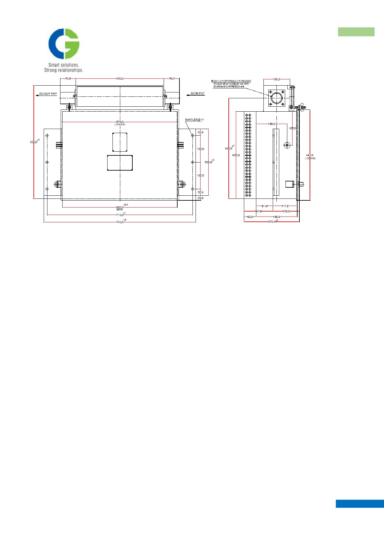
Outline drawing of Rectifier Regulator Unit
Each diode is protected against transient surges voltage by capacitor C1. The whole bridge is protected against
high frequency surges by capacitor C3. The DC output is filtered by capacitor C2.
3.3 Current Transformer
The current transformers are used to sense the load current for the current limit. When the primary winding of
each current transformer carries load current, the secondary winding feeds a three phases voltage to the
rectifier RT2 in the regulator rack.
3.4 The regulator rack
The regulator rack consists of the following parts.
3.4.1 Excitation Transformer
This is a one winding transformer with tappings for input and output. The transformer steps down the voltage
for the field coils. The output of the transformer is taken in the field through the magnetic amplifier before
being rectified by field rectifier diodes.
The transformer has five set of terminals.
Terminals 14 & 15, input from phase 14 & 15 of alternator. Centre tapping, terminal 19, goes to the -ve
terminal for field supply.
Terminals 18 & 161 are the output terminals and go to the respective terminals on the magnetic amplifier.
MAINTENANCE MANUAL FOR DETC-US
AUXILIARY ALTERNATOR
3.4.2 Magnetic Amplifier
The magnetic amplifier forms the nucleus of the regulator circuit; It works on the principle of saturation of
magnetic core. The equipment has six sets of windings:
Two load windings:
18 - 162 & 17 - 161
Four control windings:
10 - 11, 26 - 27, 29 - 30 & 20 - 40
(Of these only 10-11 and 20-40 are used in the circuit.
10-11 for voltage and current control & 20-40 for gain
control).
The field current passes through the load windings of the magnetic amplifier. Subject to the command from
the voltage and current sensing circuits, manifested through the control winding 10-11, the load winding offers
variable impedance of the field circuit.
3.4.3 Field rectifier unit
The two silicon diodes D3, D4 acts as a full wave rectifier for the field supply. These diodes conduct
alternately. The rectified current from the diodes is taken through the feedback winding 20-40 of the
magnetic amplifier. Terminals 20 & 19 form the +ve & -ve terminals form the field assembly.
3.4.4 Free - Wheeling Diode
In the normal circumstances this diode D5 has no function. But should there be any reason for a surge from
the field circuit which will have a polarity opposite to that of excitation, this diode will conduct avoiding
creepage of the surge voltage to more important components like Magnetic Amplifier.
3.4.5 Rectifier Bridge
Each bridge RT1 & RT2 is made up of six silicon diodes, connected for three phase full wave rectification,
RT1 supplies the rectified voltage for voltage detector DT1 which is also the voltage developed by the
alternator, RT2 rectifies the three phase voltage developed at C.T secondary side and supplies to the voltage
detector DT2.
3.4.6 Voltage Detector DT1, DT2
These voltage detectors serve the function of providing necessary “error signal” for voltage regulation &
current limiting.
It consists of a network of zener diode, potential divider & rheostat. The voltage drop across resistance can
be adjusted by varying the resistances Rh1 & Rh2.
In the case of DT1 when the output voltage exceeds the voltage of the alternator the voltage drop across R1
will be sufficient to cause zener break down and this will send a current through the control winding 10-11 of
the magnetic amplifier.
MAINTENANCE MANUAL FOR DETC-US
AUXILIARY ALTERNATOR
Similarly, in the case of DT2, when the current reaches preset value the voltage induced in the secondary of
the current transformer after rectification by RT2 will be sufficient to cause conduction of the zener diode
and to produce the necessary error signal to magnetic amplifier for current control.
Zener diode has a characteristic that the diode starts conducting only at a designated voltage (zener voltage).
The voltage across the zener will be maintained even if the voltage input to the circuit is increased. Thus it
serves as base for comparison.
3.4.7 Blocking diodes
Diodes D1 & D2 are used to block the current from one zener to the other. Diode DI prevents creepage of
current from DT2 to DT1 and D2 prevents current from DT1 to DT2. This is achieved by the unidirectional
property of diodes.
3.4.8 Regulator failure relay
One number over voltage under voltage relay is provided to indicate the failure of the regulator. When
output terminal voltage of the regulator drop below the pre-set value the relay trips and indication lamp will
glow. And same in the case of over voltage.
3.4.9 Regulator failure indication lamp
One number indication lamp is provided to show the failure of the regulator. This is connected in series with
the battery and the contacts of the regulator failure relay.
4. WORKING OF REGULATOR
The three phase output from the alternator is rectified by the bridge connected silicon diodes. The DC
excitation to the field is obtained by full wave rectification of alternating current provided through the load
windings of the magnetic amplifier.
The voltage induced in the alternator winding depends on the speed of revolution of rotor and on the
excitation current. In the absence of voltage detector and magnetic amplifier, the voltage of the alternator
will rise indefinitely due to the positive feed back limited only by saturation of stator. But as soon as the
preset voltage is reached the zener diode in detector DT1 conducts and sends a control current through the
magnetic amplifier winding 10-11. The flux produced by the control current is in such a way that it opposes
the flux produced by the load windings, there by increasing the impedance of the field circuit. This increase
in field impedance reduces the field current and feed back the output voltage to the normal value required.
The current limiting is also achieved in a similar manner. When the pre-determined load current is delivered
MAINTENANCE MANUAL FOR DETC-US
AUXILIARY ALTERNATOR
by the alternator, the secondary voltage of the CT after rectification by bridge RT2 will provide the necessary
“error signal” for the magnetic amplifier. In this case also the voltage drop across the resistance will be
sufficient to cause the zener diode in DT2 to conduct. The control current from this also passes through the
same control winding 10-11. The effect of this control current is to retain the current at the limited value and
to reduce the voltage. For a sustained overload, the generator voltage will fall to the battery voltage &
relieve the alternator immediately, thereby reducing the chances of damage due to the load.
5. ROUTINE MAINTENANCE
5.1Alternator :
• Check the suspension and securing nut after every round trip.
• Inspect the terminal box for water tightness.
5.2 Regulator box
See that all securing fasteners are held properly
Keep the cover tightly closed.
Ingress of water and dust in the regulator box will damage the equipment beyond repair.
6. PERIODICAL OVERHAULING
6.1Alternator
• Clean and regrease the bearing after removing the bearing from the bearing housing. The bearing
is designed for regreasing in workshops at long intervals of 5000 hours in operation. However, it
is recommended that during POH, the bearing should be regreased.
• Before using new grease the bearing should be thoroughly cleaned with white spirit. 24 gms. Of
lithon 2 should be used for refilling.
• The bearings should be changed, if it is found defective during inspection.
• Clean the mating surface of the end shield, before assembly the surface should be coated evenly with
gasket shellac.
• While removing and placing the rotor, care should be taken to see that the rotor does not rub over the field
coils.
• If any grease has crept into the stator surface clean it before assembly.
• If stator & rotor parts are found rusty, clean and slightly coat with Dr. Beck make E1mo65E/R insulating
MAINTENANCE MANUAL FOR DETC-US
AUXILIARY ALTERNATOR
varnish.
6.2
Regulator box
If no failure or defect has been observed, clean & tighten all components and ensure that all joints and connections
are properly tight.
7. REMOVAL OF ROTOR & BEARINGS
The following procedures should be adopted for dismantling alternator.
a. Remove the fan cover from one end after removing the M10 screws.
b. Using a box spanner of size 13 unscrew the two screws securing the screw locking washer.
If these screws have been locked by steel wires or by tack welding,
proceed only after removing the locking arrangement.
c.
Remove flange from the shaft.
d.
Bend back the SKF lock washer M8 12 from DE side
e.
Remove lock nut SKF KM 12 from DE side.
f.
Remove all the end shield fixing screws from NDE side.
g.
Locate the two tapped holes on the endshield on NDE side along with the rotor and bearing on NDE
side and screw in two M I0 screws. The two screws should be turned in equally, as the screwing
progress the endshield comes out gradually along with the rotor bearings on NDE side. The endshield
and bearing on DE side remain and in its place.
h.
Gently pull out the rotor from the stator. Care should be taken to see that the rotor does not pull over the
stator coils.
i.
After removing the endshield fixing screws from NDE side, remove the end shield by screwing into
M10 screws in the tapped holes on the endshield.
j.
The endshield on NDE side now lies along with the rotor. Bend back the lock washer M8 12 & remove
the locknut KM 12. Remove the bearing covers. Remove the spacer, pull out the end shield from the
shaft. The end shield comes out along with the bearing. (The inner race remains on the shaft).
k.
The bearing can be removed from the end shield by gently pressing out, in a hydraulic press. The
pressure should be applied gradually.
MAINTENANCE MANUAL FOR DETC-US
AUXILIARY ALTERNATOR
l.
The inner race can be removed by slightly heating the inner race by using an induction heater. The ring
comes out of the shaft on slight knocking.
8. ASSEMBLY
Assembly of the alternator can be proceeded on the reverse way with special care on the following points:
a. The inner race of the bearing should be heated in an oil bath at about 80 deg. C to 90 deg. C
before insertion on to the shaft.
b. The end shield should be heated in an electric oven to about 120 deg.C before locating the
bearing in it.
c. In order to seat the bearing properly internal bearing cover should be fixed on to the end shield before
heating the end shield.
d. Before inserting the bearing to the shaft, the internal bearing cover should be placed in its position.
e. If this is not done it is impossible to assemble the machine
f.
Gasket shellac (Addison) should be applied evenly on all the mating surfaces of bearing cover and end
shield.
g. Take special care to see that the bearing comes on the terminal box side.
h. While removing and fixing the SKF lock nuts use a hook spanner. Never use any tools for this purpose
i.
The cooled bearing put in back to back arrangement is placed inside the heated endshield and outside
bearing cover assembly. The whole thing is then inserted into the shaft, which will mate with inside
bearing cover.
9. DO’s AND DON’Ts FOR THE EQUIPMENT
A. ALTERNATOR
a. Open up the terminal box once in two weeks and clean up the dust if any accumulated in it.
b. Check up the tightness of connection once in two weeks.
c. Keep the terminal box tightly closed
d. Regreasing should be made after thoroughly cleaning the bearings with while spirit. It is preferable to
regrease the bearing only during POH.
e. Don’t overgrease the bearings.
f.
The field connection on the alternator terminal box should not be reversed.
g. Use the cable sockets and cable glands for connections.
h. Never give separate excitation to the field. It will damage the regulator components.
B. REGULATOR
MAINTENANCE MANUAL FOR DETC-US
AUXILIARY ALTERNATOR
a. Don’t disturb the setting on the voltage and current potentiometer. Best results are obtained with the
settings made by the manufacturer.
b. Don’t open the regulator box unless a defect is observed.
c. Don’t use a megger to test the components. Use a multimeter.
d. If earth resistance is to be measured, disconnect the leads from alternator and load.
e. Short circuit all the seven terminals, before using a meggar.
f.
Don’t reverse the field terminal connections.
g. If a diode is to be replaced its base should be evenly coated with silicon grease.
h. In no circumstances the burden resistance setting should be disturbed.
i.
Use only HRC fuses in phase and field circuits
MAINTENANCE MANUAL FOR DETC-US
AUXILIARY ALTERNATOR
NOTES
-----------------------------------------------------------------------------------------------------------------------------------
-----------------------------------------------------------------------------------------------------------------------------------
-----------------------------------------------------------------------------------------------------------------------------------
-----------------------------------------------------------------------------------------------------------------------------------
-----------------------------------------------------------------------------------------------------------------------------------
-----------------------------------------------------------------------------------------------------------------------------------
-----------------------------------------------------------------------------------------------------------------------------------
-----------------------------------------------------------------------------------------------------------------------------------
-----------------------------------------------------------------------------------------------------------------------------------
-----------------------------------------------------------------------------------------------------------------------------------
-----------------------------------------------------------------------------------------------------------------------------------
-----------------------------------------------------------------------------------------------------------------------------------
-----------------------------------------------------------------------------------------------------------------------------------
-----------------------------------------------------------------------------------------------------------------------------------
-----------------------------------------------------------------------------------------------------------------------------------
-----------------------------------------------------------------------------------------------------------------------------------
MAINTENANCE MANUAL FOR DETC-US
CHAPTER IX
CONTROL GEAR EQUIPMENT
Maintenance Manual
DIESEL ELECTRIC TOWER CAR | UNDER SLUNG TRANSMISSION
CONTROL GEAR ITEMS
CHAPTER IX
CONTROL GEAR ITEMS
Master Controller
Master Controller is used to select various speed of Diesel Engine as well as to change the direction of
vehicle. It has two handles, which function is explained below:
i) Accelerating Handle:
This handle has nine notch positions i.e. 0-1-2-3-4-5-6-7 & 8. The vehicle will accelerate as the driver moves
the handle from a lower notch to a higher notch.
ii) Reversing Handle:
It has three positions i.e. REVERSE - OFF - FORWARD. The position of this handle decides the direction of
movement of train.
A locking key is also provided. Reverse Handle can not be operated unless the locking key is inserted in the
keyhole & rotated by 90o clockwise.
Mechanical interlocking is provided to prevent unauthorised operation of either accelerating or reversing
handle. It has following features:
I) Reverse handle can be moved to either
“Forward” or
“Reverse” position only when the key is inserted
inside the keyhole & rotated by 90o clockwise.
ii) Accelerating handle can be moved only when reverse handle is either at “Forward” or “Reverse" position
i.e accelerating handle cannot move when reverse handle is at “0” position.
iii) Reverse handle can be moved only when the accelerating handle is at “0” position.
iv) A deadman’s mechanism is provided with the accelerating handle. When the accelerating handle is
depressed deadman contact closes & when the handle is released, it opens to cut off the traction control
supply & thus the power to Traction Motors. The mechanism is so designed such that it trips only when the
“Reverse Handle” is either at forward or reverse position.
v) Key can be removed only after the accelerating handle is brought to “off ” position and reverse handle is
brought to “0” position.
MAINTENANCE MANUAL FOR DETC-US
CONTROL GEAR ITEMS
Make & Type No
:
Inder Engg., 9MC-MU-018
Operating Voltage
:
110V DC
Current Rating
:
10 Amps (Thermal)
Motor Overload Relays
It is used for protection of Traction Motor from current overloading.
The relay has two coils -
a) Operating Coil: It is single turn coil, which passes through the yoke of relay.
b) Resetting Coil: This coil is provided for resetting the overloaded relay to resume normal operation. This
coil is suitable for remote resetting operation.
The relay has six auxiliary contacts (3NO+3NC) for use in control & indication circuits. When the motor
current exceeds the value at which the relay is set to trip, the yoke gets magnetised, which pulls down the
armature of main coil. At the same time armature of reset coil is released and position of auxiliary contacts is
changed.
Thus the supply to E.P.Contactor coil, through auxiliary contacts of overload relay is cut off, which in turn
breaks the power circuit thus preventing the motor from overloading.
Make & Type No
:
Inder Engg
Current Rating
:
900 Amps
Reset Coil
:
DC 110V, 1 Minute
Reset Coil Resistance
:
160 Ω
Calibration range
:
600A, 700A, 800A and 900A
Trip Coil Setting
:
650A.
Capacity of contact (Auxiliary)
i)
Thermal
:
3A
ii)
Rupturing
:
0.5A, 110 V.
Min. operating voltage (Hot)
:
< 66V
MAINTENANCE MANUAL FOR DETC-US
CONTROL GEAR ITEMS
E.P. Reverser
E.P.Reverser is used to change the direction of field current of Traction Motor, thus changing the direction of
the coach. It is a 4-Pole off load switch, which carries rated current during its operation. It has two sets of
Magnet valves, one each for forward and reverse operation. It has 4 power contacts and 4 auxiliary contacts
(change over type). When forward coil is energised, all 4 power contacts and 4 auxiliary contacts operate &
make connection in forward direction. Similarly reverse connection is made when reverse coil is energised.
Make
:
Inder Engg.
Rating of main contacts
:
600 Amps (Thermal)
No. of main poles
:
4 Nos. (change over type)
Rated Operating Air Pressure
:
5 Kg/cm2
Rated coil Voltage
:
110 V DC
Rating of Auxiliary Contacts
:
10 Amps (Thermal)
Min. operating voltage
:
68 Volts
Min. Operating Pressure
:
4 Kg/cm2
Electro-pneumatic Contactor
EP Contactors are required to connect / isolate the Traction Motors to / from the power circuit. These
contactors are On-Load Switches and are required to isolate the motors on load from the power circuit.
These EP Contactors are fitted with a cylinder and piston, which operate main contacts of copper with silver
/ silver cadmium oxide tips. These silver tips are protected from damage due to arcing. A blow-out coil is
fitted to extinguish the Arc when the main contacts are open (on-load) and this is assisted by an arc chute.
When the magnet valve is energised, air is admitted to the cylinder. This causes the piston to rise and main
contacts close.
One set of auxiliary contacts are provided, when the magnet valve is energised the auxiliary contact arm
shall move upwards and shall cause the auxiliary contacts to close.
When the magnet valve is de-energised, air exhausts from the cylinder and the piston moves downwards to
open the main contacts and at the same time the auxiliary contact arm also moves downwards and open the
auxiliary contacts.
MAINTENANCE MANUAL FOR DETC-US
CONTROL GEAR ITEMS
Make & type
:
Inder Engg., 9-24PC2-15
Operating Voltage
:
110 VDC
Operating pneumatic pressure
:
4.5 Kg/Cm2
Main Contacts Rating
:
1500 Volts, 1390 Amps
Auxiliary Contacts Rating
:
3Amps @ 110 VDC
Load Ammeter Shunt
Two separate load ammeter shunts are provided one for motor no. 1 and other for motor no. 2 to measure the
motor current.
Rating
:
1000A / 75mV
Make
:
AE, Mumbai
Ground Fault Relay
Ground fault relay operates in the event of ground fault in power circuit. It is a current operated relay. Once
the ground fault has occurred, the relay gets latched & it can be reset manually with the help of reset knob
provided on the relay. A cutout switch is provided in series with the relay coil to isolate the relay from power
circuit.
Trip Coil Setting
:
180-280 mA
Rating of Auxiliary Contacts
:
5 Amps (Thermal)
Resistance of Coil
:
630Ω at 20° C.
General Purpose Relay - 1
It consists of General Purpose Relays for sequencing, interlocking & protection.
Make & Type No
:
Schneider
Coil Voltage
:
120V DC
Contact Arrangement
:
4 NO
Add on Block
:
4 Amps; 2NO+2NC or 4NC
MAINTENANCE MANUAL FOR DETC-US
CONTROL GEAR ITEMS
General Purpose Relay - 2
Make & Type No
:
Schneider
Coil Voltage
:
24V DC
Contact Arrangement
:
4 NO
Add on Block
:
4 Amps; 2NO+2NC or 4NC
Resistor Panel
Resistor panel provides external resistance to the exciter stator coils of Traction Alternator for limiting the
excitation current to a safe value in the event of failure of excitation control function.
Make & Type No
:
PEC; PPR 300
Rating
:
12 Ω , 300 watts
Bypass switches:
Bypass switches are used to bypass a protection circuit when the corresponding protection circuit is not
working properly or intended to bypass under strict vigilance. The circuits/relays, which can be bypassed,
are listed below with their operating pressure range:
Make & Type No
:
RGK; 1510.4430
SPST
:
15 Amps, 250V AC/DC
Driver’s Control Switch Box:
Driver’s control switch box contain switches for various control operations. It has spring-loaded switches as
well as change over type switches.
All the switches in the top row are mechanically interlocked with Driver’s Control Switch removable handle.
The switches can be unlocked by pressing the handle down by 10mm and turning it clockwise by 45 degrees.
The handle can be inserted/removed in OFF position only. Moreover, the top row switches are automatically
reset to normal position when the handle is removed.
10 Auxiliary switches are also provided, which operate when the Key is inserted and kept in ON position.
MAINTENANCE MANUAL FOR DETC-US
CONTROL GEAR ITEMS
Make
:
Inder Engg.
Thermal Current rating of contacts
:
10 Amps
Breaking Capacity of Contacts
:
2Amps inductive Load at 110V DC
Main Switches
:
2NO + 1NC
Driver’s Control Switch
:
8NO + 2NC
Lamp rating
:
125V, 10W
Wire wound Resistor
:
250 Ω ± 3%, 3W
Engine Control Switch
Engine control switch has two positions namely ‘IDLE’ & ‘RUN’. The switch put-off the excitation of
Traction Alternator there by preventing Power to Traction Motors unless it is switched to ‘RUN’ position &
Master Controller is taken to notch 1 or higher notches.
Make
:
JSL
Brand Name
:
JMP
Rating (Thermal)
:
25 Amps, 500V AC
Contact Arrangement
:
3NO + 3NC
Load Ammeter and Ammeter selection switch
Ammeter and Selector Switch is provided for indication/measurement of load current. Using selector switch
load current of Traction Motors 1 & 2 can be selected. Motor current of rest of the motor currents cannot be
measured with the selector switch & Load ammeter. Load Ammeter has a basic rating of 75 mV and is
shown in 1000 Amps DC range.
Load Ammeter
Make & Type No
:
AE; SM144
Rating
:
0-75mV/0-1000 A
Dimension
:
144 x 144 mm
Ammeter Selection Switch
Make & Type No
:
KAYCEE ; RP125B
Rating
:
16 Amps AC/DC, 2 way with off
MAINTENANCE MANUAL FOR DETC-US
CONTROL GEAR ITEMS
Motor cutout switch
2 Nos. switches are provided in Control Cubicle to isolate either a single motor or a pair of motors in the
event of fault on Traction Motors. The operational sequence of switches is listed below.
1) MCS-1:
ALL in /Motor 1 out / Motor 3 Out / Motor 1 & 3 Out
2) MCS-2:
All in /Motor 2 Out / Motor 4 Out / Motor 2 & 4 out
“Off” position indicates normal/healthy operation.
Make
:
KAYCEE (programme Switch)
Rating
:
16 Amps, 250V AC/DC
No of Poles & Positions
:
4 Pole & 4 Way
Voltmeter and voltmeter switch
One no. Voltmeter and one no. Voltmeter switch is provided in Control Cubicle, for measurement of system
control voltages 110 V DC & 24 VDC. Voltmeter switch is connected in series with the voltmeters. The
indication on voltmeter is available only when the switch is turned on.
Voltmeter
Make & Type No
:
AE; SQ96
Rating
:
0-150V DC
Dimension
:
96 x 96 mm
Voltmeter switch
Make & Type No
:
RGK; 1510.4430
Rating
:
15 Amps, 250V AC/DC
Battery (110V) Cut out switch
This switch is provided to isolate entire control and auxiliary circuit from 110 V battery. 32 Amps & 63
Amps in-built fuses are also provided in the switch.
Make & Type No
:
Salzer
MAINTENANCE MANUAL FOR DETC-US
CONTROL GEAR ITEMS
Contact Rating
:
300 Amps
Reverse Current Diode
Reverse current Diode is provided for protection of batteries against discharging, when
the
18.5 kW
Auxiliary Alternator supply is not available.
Make
:
Ruttonsha
Average Forward Current
:
150 Amps
PIV at rated junction temperature
:
1000 V
Battery (24V) Isolating Switch
Make & type
:
Inder Engg.
Rating
:
250 Amps, 415V, 50 Hz
Timers
Make & type
:
ETR650, Siemens
No. of Changeover Contacts
:
4 Nos.
Local/Remote Switch
Type & Make
:
Kaycee (Program Switch)
Rating
:
16 Amp, 2-pole, 3-way
Instrument Lamp
Type & Make
:
Siemens, 3SB0420-2A
Rating
:
110 VDC
Lamp
:
110 VDC, 2W
Auxiliary Fuse Panel
Type & Make
:
Siemens, 3NH3 030
MAINTENANCE MANUAL FOR DETC-US
CONTROL GEAR ITEMS
Rating
:
125 Amps
Fuse Rating
:
32Amps, 3NA1001
Fuse Rating
:
63 Amps, 3NA1015
Hand Lamp socket
Ratings
:
10 Amps, 3-pin
Miniature Circuit Breaker (MCB)
MCB’s are used to protect electric circuits against overloading caused by excessive currents due to sustained
overloads or short circuits. MCBs are used in CAB-1 and CAB-2.
Make
:
Schneider
Specification
:
SPEC/E-12/1/04 & SKEL-3700
Ratings
:
5A, 10A, 15A & 30 Amps
LED Indication Panel
36 LED Module indication panel is mounted on the Driver’s Desk-DPC. The LED indications are provided
to identify various fault & healthy features of the vehicle.
Make & Type
:
Inder Engg & 36 LED
Voltage of operation
:
110 VDC
MAINTENANCE MANUAL FOR DETC-US
CONTROL GEAR ITEMS
NOTES
-----------------------------------------------------------------------------------------------------------------------------------
-----------------------------------------------------------------------------------------------------------------------------------
-----------------------------------------------------------------------------------------------------------------------------------
-----------------------------------------------------------------------------------------------------------------------------------
-----------------------------------------------------------------------------------------------------------------------------------
-----------------------------------------------------------------------------------------------------------------------------------
-----------------------------------------------------------------------------------------------------------------------------------
-----------------------------------------------------------------------------------------------------------------------------------
-----------------------------------------------------------------------------------------------------------------------------------
-----------------------------------------------------------------------------------------------------------------------------------
-----------------------------------------------------------------------------------------------------------------------------------
-----------------------------------------------------------------------------------------------------------------------------------
-----------------------------------------------------------------------------------------------------------------------------------
-----------------------------------------------------------------------------------------------------------------------------------
-----------------------------------------------------------------------------------------------------------------------------------
-------------------------------------------------------------------------------------------------------------------------------------------
MAINTENANCE MANUAL FOR DETC-US
CHAPETR X
MAINTENANCE INSTRUCTIONS
CONTROL GEAR EQUIPMENT
Maintenance Manual
DIESEL ELECTRIC TOWER CAR | UNDER SLUNG TRANSMISSION
CONTROL GEAR EQUIPMENT
CHAPTER X
MAINTENANCE INSTRUCTIONS
CONTROL GEAR EQUIPMENT
1. INTRODUCTION
ELECTRIC TRACTION EQUIPMENT must be reliable in order to avoid failures, traffic delays and loss
of revenue due to lack of public confidence. The equipment must also operate cheaply for economical
operation in service.
These requirements can only be fulfilled if preventive measures are taken, in the form of periodical
Service Maintenance and Overhaul, which must be thoroughly organised and meticulously and
conscientiously carried out at the times recommended in this Maintenance manual.
The intervals, at which Service Maintenance and Overhaul are carried out, are calculated on the basis of
either time or distance travelled and will depend upon the type of equipment, the nature of service, and
climatic conditions. In the case of diesel-electric equipment, the intervals may depend upon the number of
hours the engine runs.
If the weekly mileage is regular and approximately constant, a time-period basis of maintenance is
probably more satisfactory; but if the weekly, monthly or seasonal mileage is subject to wide variations,
the use of the time period basis would introduce differences in the distance travelled, in which case the
distance basis of maintenance would be preferable.
1.1 Service Maintenance
This is carried out on a regular basis in order to maintain the equipment in sound condition and to prevent
service failures. If maintenance is carried out efficiently at the established periods, the equipment will
operate reliably between overhauls.
MAINTENANCE MANUAL FOR DETC-US
CONTROL GEAR EQUIPMENT
Maintenance is usually carried out in the running shed and comprises examination, cleaning, lubrication,
any necessary adjustments for wear, and changing worn consumable parts such as carbon brushes,
contacts, arc chutes etc. fitting new or re-conditioned parts.
Consumable part must not be allowed to wear beyond the specified minimum dimensions. If it is
estimated that a part will become fully worn before the next maintenance occasion, it must be replaced by
a new or reconditioned part. In addition, a sufficient margin for wear should be allowed in case a normal
maintenance occasion is missed, due to the hazards of severe weather or other unusual traffic conditions.
The intervals at which the various maintenance operations are carried out can only be determined by
observation and experience. At first, the intervals should be about one week or 3200 km, and they should
be lengthened gradually as experience is gained without, of course, endangering the reliability of the
equipment. Eventually, when the maximum intervals have been established, they should, if possible, be
arranged to fit the occasions when the vehicle visits the running shed for maintenance of the mechanical
parts of the vehicle.
1.2 Overhaul
This is carried out in the workshop, and comprises repairing and reconditioning the equipment; that is,
dismantling, replacing worn or defective parts by new or reconditioned components, re-assembling the
equipment and testing it for correct operation.
The periods between overhauls are best determined by withdrawing the equipment for service after a
period of two years or 160,000 km, and subjecting it to a detailed examination, which will also necessitate
a certain amount of dismantling. If it is found that the equipment has not reached the Overhaul state, it
should then be returned to service.
In general, periods between overhaul should not be less than three years. These periods are, however,
capable of being extended to five years or more provided.
a)
Modern high-grade lubricants are used.
b)
Maintenance is efficiently carried out.
c)
Thorough attention is given to cleanliness.
MAINTENANCE MANUAL FOR DETC-US
CONTROL GEAR EQUIPMENT
Experience on many railways, in different parts of the world, has shown that more frequent maintenance
and overhaul are necessary for the mechanical parts of the vehicle than for the electrical equipment. As
the program for the electrical work must be built up gradually, and the periods extended as experience is
gained, every endeavour should be made to fit the electrical program into the mechanical program, in
order to minimise the time that the vehicle is out of service.
1.3 Records
Accurate records should be kept of the maintenance and overhaul work carried out in order to determine
the amount by which the Maintenance and Overhaul periods may be extended. "Cardex" is a suitable
system for this purpose, and it would contain card for each of the items on which records are to be kept,
for example, armatures, machine stators, gears, pinions pantograph wearing-strips (if fitted), cleaning
filters and radiators, etc.
2. CLEANLINESS
Cleanliness is essential to good maintenance and trouble-free service, and the work of cleaning must be
thoroughly carried out at the established intervals.
Metallic dust from the wheels and brake shoes is detrimental to equipment and, if the dust is allowed to lie
on insulation surfaces or to penetrate coils, it can cause electrical failure.
This dust, when dry, is usually easy to remove, but if it becomes bound with water or oil, its removal is
more difficult. Operators must, therefore, avoid leaving deposits, which have this binding action.
The degree of cleanliness, which can be maintained, depends to a large extent on the location of the
equipment and whether it is totally enclosed, ventilated, or outside-mounted.
When no ventilation is required because the production of heat is low, apparatus is enclosed in dust-proof
cases, compartments or cupboards; ensure that the rubber or felt jointing of the covers or doors is
maintained in good condition.
Ensure that the devices for keeping covers and doors closed are also well maintained and lubricated when
necessary.
Compartments, which cannot be seated easily, for example when they are provided with sliding doors, are
sometimes pressurised with filtered air. When this is the case, it is important to ensure that any failure of
air supply is restored without delay, and the filter is cleaned regularly, or changed when necessary.
Although the frequency of cleaning totally enclosed apparatus is much less than that required for
ventilated or roof-mounted apparatus, it must not be neglected if failure is to be avoided.
MAINTENANCE MANUAL FOR DETC-US
CONTROL GEAR EQUIPMENT
Apparatus such as resistors and rectifiers, etc., which have to dissipate heat to avoid excessive
temperature, are either free-ventilated or force-ventilated with unfiltered air and require frequent cleaning,
as they readily become contaminated with dirt and brake shoe dust.
On electric vehicles on which roof-mounted apparatus is fitted, there are large porcelain insulators, which
may collect much falling dirt and therefore must be kept clean. Rubber hose for the pantograph air supply
must also be cleaned and kept free of oil and grease. Examine all roof equipment and check for
mechanical damage; remove any debris that may have lodged on the roof.
3. LUBRICATION
In general, lubricants should be used sparingly to avoid contaminating insulation and other parts of
apparatus. Clean the electrical sliding contacts of knife switches, drum switches and reversing switches
etc., periodically, then lightly smear them with 4 x grease ( supplied by Dow Corning, USA)
Pivots for contactors and hinged contact fingers, etc., are lubricated during assembly, chiefly as rust
inhibitor prior to being placed in service. Do not add lubricant at periodical maintenance because the
pivots have an extremely long life, even when operating dry, and if lubricants were added it would tend to
contaminate other parts of the apparatus, thus forming a dirt-collecting surface. Lubricate pivots only at
overhaul with grade SAE 30 oil.
Lubricate cylinders, piston, rods, sliding parts and solid (no oil-impregnated) rollers, etc., periodically
with grade SAE 30 oil.
Do not add grease to ball bearing between overhauls, unless otherwise specified in this manual; clean and
re-pack them at overhaul with Shell Alvania 3 or other approved grease. Also use this grease for smearing
the teeth of racks and pinions, and for lubricating sleeve-bearings.
Lubricate oil-impregnated rollers and bearing bushes with grade SAE 30 oil only an overhaul.
Lubricate the hinges on pantograph current-collectors with no-water-soluble grease or oil.
The foregoing information is given as a guide, and it is recommended that operators discuss with an oil
company's local representative, the lubricants best suited to the particular climatic conditions under which
the equipment will operate.
4. TIGHTNESS OF BOLTS SCREWS AND NUTS
MAINTENANCE MANUAL FOR DETC-US
CONTROL GEAR EQUIPMENT
It is essential that all bolts, screws and nuts are kept tight, because any loosening can cause failure of the
vehicle as well as damage to adjacent or associated apparatus. There is also the possibility of fire being
caused by arcing at loose terminals.
Suitable locking devices are provided in the form of high grade spring locking-washers, locking plates,
grub screws or prick-punching etc., and when dismantling take place these locking devices must be
replaced by devices of the same grade of material and in the same form as originally supplied.
Contactor contacts, which are subjected to repeated impacts, connections, which are subjected to severe
heating cycles such as those, associated with resistors, and the smaller sizes of cable terminals, are items
which are most liable to loosen.
Before the equipment enters service, carefully check every electrical connection and contact. Repeat this
check after a week and then every three months for the first twelve month's operation. If at the end of
twelve months, no further loosening is detected, it can be assumed that all connections will maintain their
tightness for an indefinite period and the checking may be discontinued.
The reason why certain contacts and connections become loose is due to the copper deforming slightly
when under pressure, and the repeated tightening causes it to become compacted and work hardened.
5. ELECTRICAL INSULATION
Insulation can fail either by puncture through the body to the material, or by surface breakdown.
Puncture depends upon the quality and thickness of the material and the voltage across it. It follows,
therefore, that if insulating material has suffered damage, it must only be replaced by material of the
original thickness and quality.
Surface breakdown depends upon the quality of the surface of the material, its cleanliness and freedom
from moisture, the surface length, and the voltage across it.
If the surface is contaminated by dirt and/or moisture it becomes slightly conducting and a minute current
will flow along a very narrow track. This current will produce heat along the track, which may cause the
dirt and/or the surface of the insulation to carbonise and the "tracking" current to increase. The action
then becomes cumulative and if the surface is not cleaned, a flashover of power current will occur sooner
or later.
MAINTENANCE MANUAL FOR DETC-US
CONTROL GEAR EQUIPMENT
The insulation surface between two points at different voltage level is known as the "creepage distance"
while "tracking" is the term applied to the visible evidence of the passage of minute currents along
irregular tracks on the insulation surface.
The top surface of horizontal insulation is, of course, mere prone to contamination by dirt and moisture
and requires more frequent cleaning than vertical surfaces.
When an insulation surface becomes damaged by tracking or has deteriorated with age, it can be
reconditioned by painting it with good anti-tracking enamel. Such as grey insulating enamel which can be
supplied by brush and which is air-drying.
When apparatus is being overhauled, take the opportunity to recondition the insulation surface, if this
appears to be necessary. If porcelain insulation suffers surface damage, fit new porcelain; however, the
surface of Mycalex insulation or resin-bonded asbestos can be reconditioned by cleaning it with fine glass
paper.
Porcelain insulators which are exposed to the weather may become encrusted with a hard surface of
carbon, copper and brake-shoe dust, etc., which is difficult to remove. By coating the surface with
Metroarc-17 or Silicone-110 grease, the contaminants may be removed easily at suitable grease intervals;
re-grease the porcelain insulators after cleaning. First, apply the grease thinly on the hands, then run the
hands lightly over the porcelain surface.
6. ARC CHUTES
The arc-chute walls, especially the area adjacent to the contact tips, will exhibit charring and soot from the
arc, and splatter from the contacts dependent on the severity and duration of the arc. Maintenance work is
rarely necessary but it is important to examine the arc chute interior for unusual charring or an unusual
extent or copper splatter on the arc horns or splatters which would indicate a fault on the Contactor or its
associated equipment.
If an arc chute is removed for inspection, always refit it in its original position so that the pattern of its
characteristic wear can continue. To achieve this, mark each arc chute to correspond with its Contactor.
When an arc chute has reached its safe limit to working life on a heavy-duty Contactor it may be
economic to extend its life by interchanging it with the chute from a lightly loaded Contactor.
Record any such interchanges so that the equipment inspectors understand the reason for wear on the
lightly loaded Contactor, the arc chute of which may normally remain almost as new.
MAINTENANCE MANUAL FOR DETC-US
CONTROL GEAR EQUIPMENT
After fitting an arc chute and during any inspection of arc chutes, ensure that the chute is securely in
position and, PROVIDED THAT THE CONTACTOR IS NOT LIVE, manually operate the Contactor and
observe that the moving contact does not foul the chute.
Ensure that spare arc chutes are always available in the running sheds, safely stacked and kept clean and
dry, to enable any damaged or badly-eroded chute to be changed quickly.
Overhaul
Asbestos develops a skin, which would not be disturbed by rough filing. Use a fine file or glass paper to
remove loose dirt and any copper globules, which may foul the moving contact.
Since un-weathered asbestos is hygroscopic, new or freshly repaired arc chutes should be kept warm and
dry. Wet arc chutes can cause low readings of insulation resistance on the power circuits.
Mycalex is not hygroscopic and the surface can be reconditioned by rough filing, if necessary.
Examine the arc chute mounting arrangement. Recondition Starting threads on mounting blocks and
screws.
Examine the arc-chute interior for signs of rubbing or transferred paint due to fouling by the piston
insulator or the blow cut coil.
Erosion in the form of creators in the side plates, and gutters in the top and bottom spreaders can often be
repaired with an arc-resisting cement provided that the erosion has not penetrated too deeply. Clean
thoroughly with glass paper the part to be cemented. The cement can then be applied with a knife and the
repair dried in an oven or air dried before the chute is used again.
Scrape any soot from the joints between side plates, splitters and spreaders and look for penetration by the
arc in to the joint. Fill any such penetration with arc-resisting cement. Use this cement to coat the joints
during re-assembly of any arc chute components, which are prone to severe penetration.
Ensure that any copper inserts in the arc-chute body are securely fixed.
Ensure that incorrect re-assembly does not allow the arc to strike any fixings, especially which pass
through the arc chute.
7. ARCING HORNS
Contactors with un-swept top arcing horns depend upon a good fit between the horn and the chute to
produce a gas proof joint for the protection of the blow-out coil; this close fit must be preserved when a
new arc chute or horn is fitted. This fit should be equivalent to a clearance not greater than 0.25 mm
between horn and chute.
MAINTENANCE MANUAL FOR DETC-US
CONTROL GEAR EQUIPMENT
When arcing horns become badly eroded at their tips and become appreciably shortened, fit new horns.
When unswept top arcing-horns become eroded to half their original thickness, fit new horns.
8. CONTACTS
Copper and silver are in general use as contact materials. Although the resistance values are similar, silver
is an inferior arcing material due to its rapid erosion and is used only for low-voltage control-circuits with
light arcing duty and for heavy-current contacts with no arcing duty.
Silver forms on its surface a low-resistance sulphide, which is brown to black in colour, and need not be
disturbed.
Copper forms an oxide, dark in colour, which has a high resistance. This would cause overheating if it
were left on a contact face.
For Contactors (which interrupt current frequently as distinct from a switch or an isolator) copper is used.
Each contact is formed in the shape of a foot with a distinct heel and toe and the moving contact is spring-
mounted on a pivot. As the Contactor closes, initial contact is made at the toes of the contacts and, as
closure proceeds, the moving contact rolls and slides over the fixed contact until final contact is made at
the heels. The action is reversed when the Contactor opens; the area of contact travels to the toes where
the contacts separate, so that the arcing when current is broken has its roots at the toes of the contacts. By
this means, the transfer of current can take place across well-mated surfaces free from arcing. The action
of the moving contact is termed KNUCKLING and is a combined rolling-and-sliding motion.
Copper contacts for light-duty contactors and for switches do not always have a distinct toe and heel with
a knuckling action, but they are always given a sliding action or WIPE, which promotes a self cleaning
action of any copper oxide that may have formed.
In general, silver contacts close with a simple butting action and such contacts are termed BUTT contacts.
The term OVER-TRAVEL is used for both wiped and butt contacts with reference to some particular
point on the moving contact or its carrier and denotes the distance that this point would travel after making
MAINTENANCE MANUAL FOR DETC-US
CONTROL GEAR EQUIPMENT
initial contact if the fixed contact were then removed. It is therefore an indication of the amount the
contacts can wear before effective contact fails.
In some applications, a Contactor may combine the properties of copper and silver by having a pair of
copper contacts with silver inserts at the current-carrying areas. On other contactors, separate pairs of
contacts in parallel are used, one pair of copper and one pair of silver, with the silver, contacts closed only
in the fully-closed position of the contractor and the copper contacts making and breaking the current.
DO NOT USE EMERY OR GLASS PAPER to clean contacts, as particles of these materials, which
might adhere to the surfaces, would cause faulty contacts.
DO NOT USE WIRE WOOL to clean contacts or any other electrical apparatus.
When contact tips are being fitted, tighten them lightly, and then finally tighten them with the Contactor
energised or firmly held in its closed position. This will give the best possible bedding of the contacts.
Some contact carriers have a ledge on which the contact locates, so that no movement can take place
during the repeated closing of the Contactor and such contacts must be seated fully with the fixing screw
and tightened before finally tightening with the Contactor fully closed.
On a rebuilt Contactor, the fixed-contact holder may be askew, thus preventing good bedding of the
contacts. Correct the contact holder by slackening its fixings, then tightening with the Contactor closed.
If the contact tips are discoloured by overheating, examine them for dirt or a coating of copper oxide on
both the front and rear conducting surfaces; check also the tightness and bedding of the contacts with each
other and with their holders. Overheating may also be caused by low contact-pressure due to worn
contacts, lack of overtravel, or a weak knuckling-spring.
Examine knuckling or contact springs periodically to ensure that no stiffness has developed in the hinge,
and that the spring has not weakened. An experienced inspector will quickly discover any abnormality of
the hinge or the spring pressure by manipulating the device.
Fit new contacts in place, if any, which have worn to half their original thickness of copper or silver.
Always fit new contacts in pairs since it is not practical to bed a new contact with a worn one. Except on
small contactors and auxiliary contacts hand filing of badly worn contacts to produce a true surface
capable of being correctly mated, is a highly-skilled operation and is rarely successful. If it is attempted,
the filing should be carried out with the contacts in a vice so that pivots or pistons are not stressed, and no
metal particles fall on the apparatus.
MAINTENANCE MANUAL FOR DETC-US
CONTROL GEAR EQUIPMENT
Transference of metal from one contact to the other occasionally occurs in inductive circuits. When this
occurs, file the contacts to their normal contour in a vice, or if the transference is appreciable, fit new
contacts.
Restrict filing in position to a fine file to remove copper oxide and small high spots on current-carrying
surfaces, also to remove copper beads from contact edges and arc-rupturing areas, since these may foul the
arc chute or may eventually drop into the moving parts of the contactor.
Copper contacts
After a few weeks in service, the appearance of the contacts will indicate where the interruption is taking
place by a rough copper surface and where current carrying takes place by bright copper areas. A dull
surface indicates where the contacts are not mating; such a surface on the heel of a contact would indicate
that the knuckling action is incomplete or that the contacts are misaligned.
A regular inspector will appreciate the condition to be expected from the contacts. Since each pair will
develop contact wear and copper splatter on the arc horns and arc chutes characteristic of its position in
the circuit. As a guide to the amount of wear to expect, the inspector should at first learn whether each
pair of contacts breaks or makes current or both or is simply used for isolation. Note that the contact wear
on some contactors with light duty or infrequent heavy duty under fault conditions, may be largely due to
mechanical hammering and knuckling. The inspector should be able to recognise unusual wear, which
may indicate a fault on the contactor or on its associated equipment.
Current-carrying areas which have a bright appearance, but which have become rough and pitted, indicate
good contact and need not be disturbed.
Silver Contacts
In normal operation only a visual inspection is necessary between overhauls.
On control circuits with inductance, arcing will cause a transfer of metal, but the resulting pip and trough
will not normally warrant attention until the overhaul stage. When appreciable erosion has occurred,
smooth the surfaces with a fine file and readjust the contact gap and overtravel.
The contact pressure of control and auxiliary contacts are not critical, but it is necessary to ensure that they
have adequate overtravel, so that they will be effective even after some wear has taken place.
On power circuits, there will be no arcing unless there is fault condition.
MAINTENANCE MANUAL FOR DETC-US
CONTROL GEAR EQUIPMENT
9. PNEUMATIC PISTONS AND CYLINDERS
9.1 Lubrication
Lubricate the cylinders and piston rods of E.P. Contactors periodically with grade SAE 30 oil, otherwise
their operation will become sluggish, and this will be detrimental to the general operation of the
equipment, particularly to rupture the arc. Lack of lubricant will also cause rapid wear of the cylinder
wall, piston rod and guide.
In order to lubricate the piston rod of an E.P. Contactor, raise the piston in its cylinder (by pressing the
magnet valve button) and add a small quantity of oil to the countersink which surrounds the rod at the top
of the cylinder to lubricate the cylinder, inject a small quantity of oil through the special oil-hole in the
cylinder wall.
E.P.Contactors with horizontally disposed cylinders do not require the piston rod to be lubricated, because
the rod passes through a clearance hole in the end of the cylinder.
Lubricate the cylinders of reversing switches and change over switches with grade SAE 30 oil, through
nipples provided in the cylinder walls. Before adding the lubricant , ensure that the piston is coincident
with its nipple. When one piston has been lubricated, move the piston assembly to the other end of its
stroke (by pressing the relevant magnet-valve button).
Before refitting a piston in to its cylinder, smear the cylinder wall thoroughly with oil.
Lubricate the rack, pinions and levers of reversing switches and changeover switches with Shell Alvania 3
or 4x grease.
9.2 Dismantling and assembling
Cylinder walls have a very fine and smooth finish to avoid wearing out the rubber piston seal. Great care
must be taken, therefore, to ensure that the surface is not damaged.
When dismantling the pistons of pneumatic contactors, it should be borne in mind that the return spring is
under compression. When the nut holding the piston to the rod is released, it will tend to fly out of the
cylinder and might be damaged or cause damage to neighbouring apparatus or injury to personnel.
MAINTENANCE MANUAL FOR DETC-US
CONTROL GEAR EQUIPMENT
Carefully examine rubber seals at over haul; fit new seals if appreciable wear is evident. Seals are slightly
elastic and must be stretched and forced over the lip on the piston in to the groove.
When fitting a piston rod, anneal the copper washer seal in order to ensure an airtight joint, when refitting
a cylinder cover, use a new jointing gasket because the existing gasket is invariably damaged during the
removal of the cover, and pieces of the old gasket adhere to the cylinder and cover. Ensure that all traces
of the old gasket are removed before fitting the new gasket.
Pneumatic cylinders for contactors are sometimes provided with a loose tube on the piston rod which acts
as a piston stop to protect the return spring against over-compression. During re-assembly work, this tube
must not be omitted.
10. RESISTORS
• The following types of resistor are most commonly used on traction equipment
• Expanded metal or metal strip wound on edge
• Wire wound, mica insulated metal tubes
• Vitreous enamelled, wire wound, porcelain tubes
• Flat, wire or metal tape wound mica elements
Maintenance
• Check that all nuts, bolts and screws are tight.
• Ensure that all connections, tapping and terminals are secure and in good condition.
• Inspect resistors for damage and overheating; if necessary fit new units.
• Examine insulators and supports, remove cracked or chipped insulators and fit new ones.
• Wipe insulators with clean, dry cloth-Blow-out resistor banks with dry compressed air.
Overhaul
• Repeat maintenance.
MAINTENANCE MANUAL FOR DETC-US