8 WHEELER DIESEL ELECRIC TOWER CAR WITH UNDERSLUNG TRANSMISSION. OPERATING & MAINTENANCE MANUAL (2019) - page 2
CIRCUIT DESCRIPTION
current shall be known from Battery Charging Ammeters provided on the Control Cubicle (Cab-1). 24 VDC
Battery supply is used for cranking the Diesel Engines.
3.3 CIRCUIT DESCRIPTION
Preparing Diesel Electric Tower Car/US for operation: -
a.
All the MCBs (110 VDC & 24 VDC) are in ON position.
b.
Engine Control Switch Mounted on Driver’s Desk is in IDLE position while Diesel Engine(s)
starting.
c.
Motor Cutout switches mounted on control cubicle cabin-1 is in “NORMAL” Position. Depending
on the faulty motor, position of the switch is changed to appropriate condition to isolate the faulty
Traction Motor.
d.
Local/Remote switches mounted on the Control Cubicle-1 are in “Remote” Position when the Diesel
Engine is started from driver’s desk. It is in “Local” position when the Diesel Engine is started
locally from the push button station mounted under the frame.
e.
All the by-pass switches are in OFF position.
f.
Battery Isolating Switch - BIS (110 Volts DC) is in “AA1&2 in CKT” position and BIS (24 Volts
DC) is in ON position.
g.
Driver’s control switch mounted on Driver’s Desk is in “ON” position.
h.
Hydraulic oil level switch (HOLS1 [2]) is in close condition, if the oil level is above the specified
limit.
i.
Diesel Engine mounted water temperature switch (TS11 [12]) is in close condition, if the water
temperature is below set position.
j.
Diesel Engine mounted lubricating oil pressure switch (PS11 [12]) is in open condition before
cranking of Diesel Engine.
k.
Diesel Engine mounted overspeed switch (SS11 [12]) is in close condition, if the speed of the Diesel
Engine is below overspeed set speed.
l.
Cooling water level switch (CWLS1 [2]) is in close condition, if the water level is above set level.
m.
Ensure the Master Controller Reverse handle in “OFF” position and Main Handle position is in ‘0’
position.
MAINTENANCE MANUAL FOR DETC-US
CIRCUIT DESCRIPTION
3.4 CRANKING OF DIESEL ENGINE
Before starting the Diesel Engine, circuit needs to be reset, which bypass the safety system during starting.
The same is accomplished using “Ready to Start” spring loaded switch mounted on the Driver's Desk.
During starting Engine Trip Relay FC21 (FC22) is energised and “Engine-1 (2) Trip” & “Engine-1 (2) OFF”
indications glow. As soon as the switch is operated, Relays R11 (R12), R21 (R22), R41 (R42), R51 (R52)
and R61 (R62) are energised and cut-off supply to Engine Trip Relay FC21 (FC22) & both the indications go
off. Now the circuit is set for Diesel Engine cranking. Press “ON” the Diesel Engine-1 ON” spring loaded
switch mounted on the Driver's Desk. As soon as the contacts of the “Diesel Engine ON” switch is closed,
Engine-1 ON relay S11 (12) get energised though wire no 1654 (1655). Contact of S11 (12) inturn operates
Remote ON/OFF Relay R91 (R92) through wire 225 (226). As soon as the R91 (R92) is energised, 24 VDC
supply is available to timers TR11 (12) & TR21 (22), Idling solenoid valve & hour meter from 209 (210)
through Local / Remote Switch & Diesel Engine ON relay NO Contact. At the same time wire no 213 (214)
is energised from 209 (210) through Engine ON relay contact and supply is available to magnetic switch
provided on the Diesel Engine (wire no 215/216). As soon as the magnetic switch is energised, supply is fed
to starting motor and allows Diesel Engine to start. If the Diesel Engine is not started for set time - say 6 sec
(set value of timer TR11 (12]), the circuit will break and disconnect supply to magnetic switch. During the
Diesel Engine cranking period, lubricating oil pressure switch is bypassed by Timer 21 (22) contact. The
timer is set at approximately 8 sec. (slightly more than the engine cranking time).
3.5 SPEED CONTROL OF DIESEL ENGINE(s)
As Diesel Engine starts running from 0 RPM, speed sensors provided on the Diesel Engine develops
frequency signal and give feedback to Speed & Load Control System (LCC-107B) through wire nos. 21A
(21B) & 22A (22B). Depending up on the speed setting (Notch), LCC-107B controls the speed of the Diesel
Engine. LCC-107B starts pumping current through wire nos. 31A (31B) & 32A (32B) to Actuator provided
on the Diesel Engine till its speed reaches its set value. Once its speed is reached to set value, LCC-107B
maintains the same actuator current.
Switch ON the “CONTROL” provided on the Driver's Desk. This allows wire no. 1602 to get supply &
“CONTROL ON” indication appears. Move the Master Controller Reverse Handle to either Forward or
Reverse direction & Main Handle to Notch 1 in depressed deadman condition. There is no change in Diesel
Engine(s) speed. Move the Master Controller Main Handle to notch 2. Diesel Engine(s) speed changes to
approximately 1000 RPM. Move the Master Controller Main Handle to higher notches. Corresponding
MAINTENANCE MANUAL FOR DETC-US
CIRCUIT DESCRIPTION
speeds are 1200 RPM at 3rd Notch, 1300 RPM at 4th Notch, 1400 RPM at 5th Notch, 1500 RPM at 6th Notch,
1650 RPM at 7th Notch & 1800 RPM at 8th Notch. Depending upon the speed setting / Notch of the Master
Controller, LCC-107B(s) changes the actuator current of Diesel Engine(s).
3.6 TRACTION ALTERNATOR EXCITATION CONTROL
Change the Engine Control Switch to “RUN” position. Ensure that Master Controller Reverse Handle is in
either Forward or Reverse direction & Main Handle is in ‘0’ position with pressed deadman condition.
Switch ON the “EXC ON” switch provided in the Driver's Control Switch Box. This operation set the
control circuit for excitation. Move the Master Controller Main Handle to Notch ‘1’ position with pressed
deadman condition. As soon as the Main Handle moves to Notch 1, LCC-107B (s) get 1st notch speed
through coded signals. Meanwhile, wire no. 3 get supply through Master Controller, Excitation Control
Relay ECR1 (2) get energised and “Excitation-1 (2) - ON” indication appears in LED indication panel. This
relay opens the reset voltage 24 VDC between LCC-107B terminals 13 & 14 through wires 203E (203F) &
299A (299B). As soon as the reset voltage is released, the excitation current starts build up from terminals 23
& 24 of LCC-107B(s). Within few seconds it reaches to its maximum to match the Diesel Engine output
power (Gross power - Power Consumed by Auxiliaries). Move the Master Controller Main Handle to Notch
2. As soon as the Master Controller Main Handle is moved to 2nd notch, logic signals through wire nos. 4,5,6
& 7 changes the Diesel Engine speed using LCC-107B to 2nd notch speed i.e. 1000 RPM and excitation
changes to get the maximum output power to match with Diesel Engine output. Depending upon the V-I
characteristics (Load Conditions) of the Traction Alternator, excitation current varies through wire nos.
1901A (1901B) & 2101A (2101B) at fixed notch. External Resistance 12 Ω keeps the Excitation current
always below 10 Amps. However, the maximum Excitation current required for Traction Alternator is less
than 6 Amps. Same procedure is applicable for higher notches also.
3.7 HEALTHY & FAULT INDICATIONS:
TRACTION CONTROL SUPPLY ON (GREEN): This is a healthy indication of system. When the
“Control” Switch provided on the Driver’s Control Switch Box of Driver's Desk is in ON position, wire no
1602 gets supply and the indication glows. If this switch is in OFF condition, Diesel Engine speed control &
Traction Alternator excitation control are not possible.
MAINTENANCE MANUAL FOR DETC-US
CIRCUIT DESCRIPTION
ENGINE-1 ON (GREEN): This is a healthy indication of Diesel Engine-1. When the “Diesel Engine-1 ON”
spring loaded switch is operated i.e. Diesel Engine-1 cranking operation is performed, Relay S11 energised
through wire no.1654 & 1664 and will remain in energised condition. When the relay S11 is in energised
position, wire no. 1811 gets supply through its NO contact and hence the indication glows. In case of any
protection circuit operates, this relay de-energises and this indication goes off.
ENGINE-2 ON (GREEN): This is a healthy indication of Diesel Engine-2. When the “Diesel Engine-2 ON”
spring loaded switch is operated i.e. Diesel Engine-2 cranking operation is performed, Relay S12 energised
through wire no.1655 & 1665 and will remain in energised condition. When the relay S12 is in energised
position, wire no. 1809 gets supply through its NO contact and hence the indication glows. In case of any
protection circuit operates, this relay de-energises and this indication goes off.
ENGINE-1 TRIP (RED): This is a fault indication of Diesel Engine-1. This indication glows in any of the
following conditions.
a. Hydraulic Oil Level
-
LOW
(Normal Hydraulic oil Level is lower than the specified limit)
b. Cooling Water Level
-
LOW
(Normal Water Level is lower than the specified limit)
c. Lubricating Oil Pressure
-
LOW
(Normal Lubricating Oil pressure is lower then 10 PSI.
d. Cooling Water Temperature
-
HIGH
(Normal Cooling Water temperature is more than 95°C)
Hydraulic Oil Level & Water Level of Diesel Engine-1 is monitored by R21 & R61 Relays respectively.
Similarly, Cooling Water Temperature & Lubricating Oil Pressure is monitored by R11 & R41 Relays
respectively. Any of these operations goes wrong respective relay de-energises and which inturn energises
Engine Trip Relay FC21. When FC21 is energised, wire no. 1807 gets supply through one of its contacts and
“Engine -1Trip” indication glows.
MAINTENANCE MANUAL FOR DETC-US
CIRCUIT DESCRIPTION
ENGINE-2 TRIP (RED): This is a fault indication of Diesel Engine-2. This indication glows in any of the
following conditions.
a. Hydraulic Oil Level
-
LOW
(Normal Hydraulic oil Level is lower than the specified limit)
b. Cooling Water Level
-
LOW
(Normal Water Level is lower than the specified limit)
c. Lubricating Oil Pressure
-
LOW
(Normal Lubricating Oil pressure is lower then 10 PSI.
d. Cooling Water Temperature
-
HIGH
(Normal Cooling Water temperature is more than 95°C)
Hydraulic Oil Level & Water Level of Diesel Engine-2 is monitored by R22 & R62 Relays respectively.
Similarly, Cooling Water Temperature & Lubricating Oil Pressure is monitored by R12 & R42 Relays
respectively. Any of these operations goes wrong respective relay de-energises and which inturn energises
Engine Trip Relay FC22. When FC22 is energised, wire no. 1673 gets supply through one of its contacts and
“Engine -2Trip” indication glows. Under these circumstances, Diesel Engine shuts down.
MOTOR EARTH FAULT (AMBER): In case power circuit is grounded due to any reason, during
operation it causes Ground Fault Relay (GFR) to energise through wire no E. When the GFR is energised,
wire no. 1624 gets supply through one of its contacts, leaving an indication “TRACTION MOTOR EARTH
FAULT”. Once the GFR is energised, it is mechanically latched. Pressing reset button provided with the
GFR resets mechanical latching.
PARKING BRAKE APPLIED (RED): When the parking brake is applied, wire no 1677 energised through
parking brake governor and “PARKING BRAKE APPLIED” Indication glows.
ALTERNATOR-1 EXCITATION ON (GREEN): This is a healthy indication of system, which shows
Traction Alternator-1 excitation is ON. As soon as the Master Controller Main Handle is moved from IDLE
to Notch 1, depending upon the Reverse Handle position, either wire no.1 (Forward) or wire no. 2 (Reverse)
is energised. These wires inturn feed wire nos. 102A & 109A through reverser interlock, Equipment
Governor, Brake Pressure Control Governor and Parking Brake Governors and energise E.P.Contactors LC1
& LC3 mounted inside the Motor Switch Group Cubicle. As soon as these contactors energised, supply is fed
MAINTENANCE MANUAL FOR DETC-US
CIRCUIT DESCRIPTION
to wire no 1614A and energise Excitation-1 ON Relay ECR1. The moment the Relay ECR1 is energised,
indication glows and excitation starts building up from LCC-107B1.
ALTERNATOR-2 EXCITATION ON (GREEN): This is a healthy indication of system, which shows
Traction Alternator-2 excitation is ON. As soon as the Master Controller Main Handle is moved from IDLE
to Notch 1, depending upon the Reverse Handle position, either wire no.1 (Forward) or wire no. 2 (Reverse)
is energised. These wires inturn feed wire nos. 102A & 109B through reverser interlock, Equipment
Governor, Brake Pressure Control Governor and Parking Brake Governors and energise E.P.Contactors LC2
& LC4 mounted inside the Motor Switch Group Cubicle. As soon as these contactors energised, supply is fed
to wire no 1614B and energise Excitation-2 ON Relay ECR2. The moment the Relay ECR2 is energised,
indication glows and excitation starts building up from LCC-107B2.
HIGH COOLING WATER TEMPERATURE (HCWT) - DIESEL ENGINE 1: This is a fault
indication of Diesel Engine-1. When the Diesel Engine-1 cooling water temperature goes high (more than
the specified limit), the temperature switch provided on the Diesel Engine opens and de-energise the Cooling
Water Temperature monitoring Relay R11 through wire no 235. As a result of this, wire no. 4030A gets
supply through one of the relay contacts, leaving indication “HCWT ENG-1” on the Indication Panel.
HIGH COOLING WATER TEMPERATURE (HCWT) - DIESEL ENGINE 2: This is a fault
indication of Diesel Engine-2. When the Diesel Engine-2 cooling water temperature goes high (more than
the specified limit), the temperature switch provided on the Diesel Engine opens and de-energise the Cooling
Water Temperature monitoring Relay R12 through wire no 236. As a result of this, wire no. 4030B gets
supply through one of the relay contacts, leaving indication “HCWT ENG-2” on the Indication Panel.
AUXILIARY ALTERNATOR-1 FAILURE (RED): Before cranking the Diesel Engine-1, “AUXILIARY
ALTERNATOR-1 FAILURE” indication appears on the LED indication panel (through wire no 1683A)
provided on the Driver's Desk, as no supply is being generated by Auxiliary Alternator-1. As soon as the
Diesel Engine-1 is cranked, Auxiliary Alternator-1 starts generating power and Auxiliary Alternator proving
Relay AAPR1 energised through wire no 301 & 303. This relay AAPR1 is always in energised position.
When the relay is energised, the indication through its NC contact disappears. When the Auxiliary Alternator
- 1 stops generating power on account of a defect in the Auxiliary Alternator - 1 and/or Rectifier and
Regulator, the AAPR1 relay de-energises and Auxiliary Alternator - 1 Failure Indication appears in LED
indication panel.
AUXILIARY ALTERNATOR-2 FAILURE (RED): Before cranking the Diesel Engine-1, “AUXILIARY
ALTERNATOR-2 FAILURE” indication appears on the LED indication panel (through wire no 1683B)
provided on the Driver's Desk, as no supply is being generated by Auxiliary Alternator-1. As soon as the
Diesel Engine-2 is cranked, Auxiliary Alternator-2 starts generating power and Auxiliary Alternator proving
MAINTENANCE MANUAL FOR DETC-US
CIRCUIT DESCRIPTION
Relay AAPR2 energised through wire no 302 & 304. This relay AAPR2 is always in energised position.
When the relay is energised, the indication through its NC contact disappears. When the Auxiliary Alternator
- 2 stops generating power on account of a defect in the Auxiliary Alternator - 2 and/or Rectifier and
Regulator, the AAPR2 relay de-energises and Auxiliary Alternator - 2 Failure Indication appears in LED
indication panel.
RECTIFIER FUSE FAILURE - 1 (AMBER): In case of any one-fuse failure in Power Rectifier-1, Relay
RL1 energises through wire no. 4020. Through one of its contacts, wire no.1612A energised leaving
indication “RECT. FUSE FAILURE-1”. In case, failure of three different phase-fuses in three different
bridges in the same rectifier panel, the same is considered as Single Bridge failure. In this case also “RECT.
FUSE FAILURE” indication glows.
RECTIFIER FUSE FAILURE - 2 (AMBER): In case of any one-fuse failure in Power Rectifier-2, Relay
RL1 energises through wire no. 4020. Through one of its contacts, wire no.1612B energised leaving
indication “RECT. FUSE FAILURE-2”. In case, failure of three different phase-fuses in three different
bridges in the same rectifier panel, the same is considered as Single Bridge failure. In this case also “RECT.
FUSE FAILURE” indication glows.
RECTIFIER -1 COOLING FAN FAILURE (RED): It is a fault indication of Power Rectifier-1. Before
the Diesel Engine-1 is not cranked this indication “RECT-1 COOLING FAN FAIL” glows, as there is no
supply available to Blower Motor provided inside the Power Rectifier-1. As soon as power is available to
cooling fan motor, blower starts working and pressure switch provided inside the cubicle actuates and
through wire no.1642A Relay RCFR1 energised. Instantly, the indication goes-off. In case Air pressure
switch provided in Rectifier Cubicle-1 fails, Relay RCFR1 will not energise and Rectifier-1 cooling fan
failure indication appears in the LED indication panel.
RECTIFIER -2 COOLING FAN FAILURE (RED): It is a fault indication of Power Rectifier-2. Before
the Diesel Engine-2 is not cranked this indication “RECT-2 COOLING FAN FAIL” glows, as there is no
supply available to Blower Motor provided inside the Power Rectifier-2. As soon as power is available to
cooling fan motor, blower starts working and pressure switch provided inside the cubicle actuates and
through wire no.1642B Relay RCFR2 energised. Instantly, the indication goes-off. In case Air pressure
switch provided in Rectifier Cubicle-2 fails, Relay RCFR2 will not energise and Rectifier-2 cooling fan
failure indication appears in the LED indication panel.
GOVERNOR-1 SUPPLY FAILURE (RED): This is a fault indication of the system. During normal
working conditions, relay ER1 is energised through wire no 1612 & 1612A and there is no indication “GOV-
1 SPLY FAIL” on the indication panel. Either excitation ON/OFF switch is in OFF condition or Engine
Control Switch is in IDLE position, the Relay ER1 is De-energised. Once the relay ER1 is de-energised, the
MAINTENANCE MANUAL FOR DETC-US
CIRCUIT DESCRIPTION
indication glows on the panel. If GOV-1 SPLY FAIL occurs, excitation of Traction Alternator-1 is not
possible.
GOVERNOR-2 SUPPLY FAILURE (RED): This is a fault indication of the system. During normal
working conditions, relay ER2 is energised through wire no 1612 & 1612B and there is no indication “GOV-
2 SPLY FAIL” on the indication panel. Either excitation ON/OFF switch is in OFF condition or Engine
Control Switch is in IDLE position, the Relay ER1 is De-energised. Once the relay ER2 is de-energised, the
indication glows on the panel. If GOV-2 SPLY FAIL occurs, excitation of Traction Alternator-2 is not
possible.
TRACTION MOTOR OVERLOAD (AMBER): Due to any reason any of the Traction Motor overloads
i.e. Traction Motor current is more than 600 Amps, corresponding Traction Motor overload relay energised,
leaving an indication “TR. MOTOR OVERLOAD” on the indication panel. In case of Traction Motor
overload, supply to traction is cut-off by isolating motor contactors on the Motor Switch Group Cubicle. At
the same time, excitation of respective Traction Alternator (In case of Traction Motor 1 or 3 overload,
Traction Alternator -1 excitation cut-off & in case of Traction Motor 2 or 4 overload, Traction Alternator -2
excitation cut-off) is cut-off. To reset the overloaded traction motor circuit, press the “Traction Motor
overload reset” spring loaded switch provided on the Driver’s Control Switch Box. This operation is possible
only when the Master Controller’s Main Handle is in ‘0’ position.
MAINTENANCE MANUAL FOR DETC-US
CIRCUIT DESCRIPTION
NOTES
-----------------------------------------------------------------------------------------------------------------------------------
-----------------------------------------------------------------------------------------------------------------------------------
-----------------------------------------------------------------------------------------------------------------------------------
-----------------------------------------------------------------------------------------------------------------------------------
-----------------------------------------------------------------------------------------------------------------------------------
-----------------------------------------------------------------------------------------------------------------------------------
-----------------------------------------------------------------------------------------------------------------------------------
-----------------------------------------------------------------------------------------------------------------------------------
-----------------------------------------------------------------------------------------------------------------------------------
-----------------------------------------------------------------------------------------------------------------------------------
-----------------------------------------------------------------------------------------------------------------------------------
-----------------------------------------------------------------------------------------------------------------------------------
-----------------------------------------------------------------------------------------------------------------------------------
-----------------------------------------------------------------------------------------------------------------------------------
-----------------------------------------------------------------------------------------------------------------------------------
-----------------------------------------------------------------------------------------------------------------------------------
MAINTENANCE MANUAL FOR DETC-US
CHAPTER V
TRACTION ALTERNATOR
1. INTRODUCTION
2. SALIENT FEATURES
3. ALTERNATOR CONSTRUCTION
4. MAINTENANCE SCHEDULE
5. ALIGNMENT PROCEDURE WITH DIESEL ENGINE
6. PROTECTION OF BALL BEARING
7. LONGITUDINAL SECTION
Maintenance Manual
DIESEL ELECTRIC TOWER CAR | UNDER SLUNG TRANSMISSION
TRACTION ALTERNATOR
CHAPETR V
TRACTION ALTERNATOR
1. INTRODUCTION
This Manual comprises chapters, covering `Description', `Insulation',
`operation' and
‘maintenance’ of
alternator. Alternator has been designed and built in accordance with the generally accepted engineering
practices of Indian Railways Loco/DEMU Sheds. In case of improper installation or improper operation or
improper maintenance, machine gives rise to potential dangers which may cause serious personal injuries or
damage.
While designing this Traction alternator, aspects of user-friendly maintenance and easy manufacture were
kept in mind. Technical data have been laid down for the machines in accordance with the specifications.
It is assumed that the planning and execution of mechanical/ electrical installation, transportation, erection
/commissioning and maintenance will be carried out under the supervision of qualified personnel.
In the case of product maintenance / installation / erection / commissioning, it is advisable to take assistance
or services of the competent CG service centres or inform CG works for the assistance.
The direction of rotation is determined from the bearing end of the machine, it is a single bearing machine,
directly coupled with Diesel engine on one side and supported on ball bearing on the other side.
1.1 TECHNICAL DATA
C1009A1 AC Alternators is a Salient pole, revolving field, brush-less, self ventilated & single bearing
Traction machine. This AC generator is available with SEPARATELY EXCITED SYSTEM (with unique
LCC 107B governor of Governors America Corporation).
Description Make & type
CG, C1009A1
Drive-Details of arrangement
Direct coupled through flex plates
of bearing and coupling
No. of poles, phases & connections
8 poles, 3 phase, Star
Maximum permissible design speed
2250 rpm
One hour rating
544 A, 450 V, 245 kW at 1800 RPM
Continuous rating
• High voltage
345 A, 666 V, 230 kW at 1800 RPM
• Low voltage
718 A, 320 V, 230 kW at 1800 RPM
Class and type of insulation
• Stator
Class H
• Rotor
Class H
MAINTENANCE MANUAL FOR DETC-US
TRACTION ALTERNATOR
Resistance at 20 °C
• Rotor winding
0.74
Ohms
• Stator winding
0.0089
Ohms
(Per phase)
• Resistance per phase exciter rotor
44 mill ohms at 20 °C
• Resistance for exciter stator
7.2 ohms at 20 °C.
Details of bearings
Single Ball bearing
SKF - 6317 C/3
Grease-type,
HP LITHON-3
Capacity
250 GMs
Interval for regreasing
6 months
Repack the grease
2 years
grease requirement in new
210 Gm
Shaft bearing seating diameter
85 mm
Min. permissible radial clearance
0.03 to 0.13 mm
Mountings-Details
Directly coupled to engine
Weight
Traction Alternator
1385 kgs
Fan
17
kgs
Rotor
605
kgs
Air Filter Assembly
40
kgs
1.2 IMPORTANT HARDWARES
Bolting place
Size
Quantity
Type
Alternator mounting with main
M24 x 70 lg. P12.9
16 nos.
Socket head
bracket
Flexible coupling with rotor
M20 x 50 lg. P10.9
08 nos
Hex. Hd bolt
shaft
Alternator mounting with
M16 x 70 lg. P12.9
16nos.
Socket head
engine adopter
MAINTENANCE MANUAL FOR DETC-US
TRACTION ALTERNATOR
1.3 MAINTENANCE SHEET
Week-
6
Sr. No.
Nature of job
Monthly
Yearly
ly
Month
01.
Physical inspection
X
02.
Air outlet cover
X
03.
Air inlet duct
X
04.
Terminal box.
X
05.
Terminal connections
X
06.
Coupling bolts to engine adoper.
X
& alt. Stator
07.
Alternator fixing bolts to base rail
X
08.
Topping up of grease in bearing assy.
X
Insulation resistance of exciter stator,
09.
rotor, main stator , ex. St.
X
Pressure Cleaning
10.
X
Dismantling
11.
Once In
Fan, flex plate fixing bolts with engine
2- year
12.
flywheel
X
MAINTENANCE MANUAL FOR DETC-US
TRACTION ALTERNATOR
2. SALIENT FEATURES OF ALTERNATOR
C1009A1 AC generator is a Salient pole type, revolving field Brush-less type alternator. These AC
generators are available in a SEPARATELY EXCITED SYSTEM (with unique LCC107B of GAC,
Governors America Corporation).
The insulation system of the stator coils has been improved for higher voltage operation of the high-powered
D.E.M.U., D.E.T.C. & shunter. The traction alternator C1009A1 is capable of operation at a top unloading
voltage of 750V DC continuously.
This alternator is especially design for Indian Railways by CG. The class 200 Insulation System with
Polyesterimide Resin provides best protection against moisture, sand, salt, humidity and corrosive
atmosphere ensuring trouble free operations under the most demanding conditions.
Transient voltage dips are lower.
Liberally rated diodes have been used in rotating rectifier assembly to ensure high product reliability
specifically for rotating application.
The rotating diodes are protected by a surge suppresser, which has the ability to chop the transients from
1600 volts to less than 450 volts.
For D.E.T.C. /U.S. power requirement is maintained constant at different notches.
Voltage X current = constant
Depending upon the load requirement, Constant & rated powers have been achieved through excitation,
which have been controlled with the help governor LCC 107B, which is a special feature of D.E.T.C. /U.S.
Depending upon the load requirements of the multiple unit, Governor provides current input to exciter stator,
which induces power in exciter armature, which then rectified by diode wheel (rotating rectifier) and is fed
into main rotating field, ultimately responsible for the power output of alternator.
The diesel engine in the present case has a gross HP of 340 and input to traction is 310 HP at 38 °C of
ambient and at a speed of 1800 RPM. The higher voltage capability of traction alternator enables the
locomotive to be operated at full field of traction motors. AC Generator armature winding is housed in Stator
and field Winding is placed on Rotor. Brush-less construction of rotating rectifier gives the required amount
of excitation to the rotating field.
The excitation circuit is designed to ensure that the excitation current does not exceed by 6 Amps at any
operating point.
MAINTENANCE MANUAL FOR DETC-US
TRACTION ALTERNATOR
3. ALTERNATOR CONSTRUCTION
3.1 STATOR
Stator consists of stator frame, stator core, armature windings & terminal box.
3.1.1 STATOR FRAME
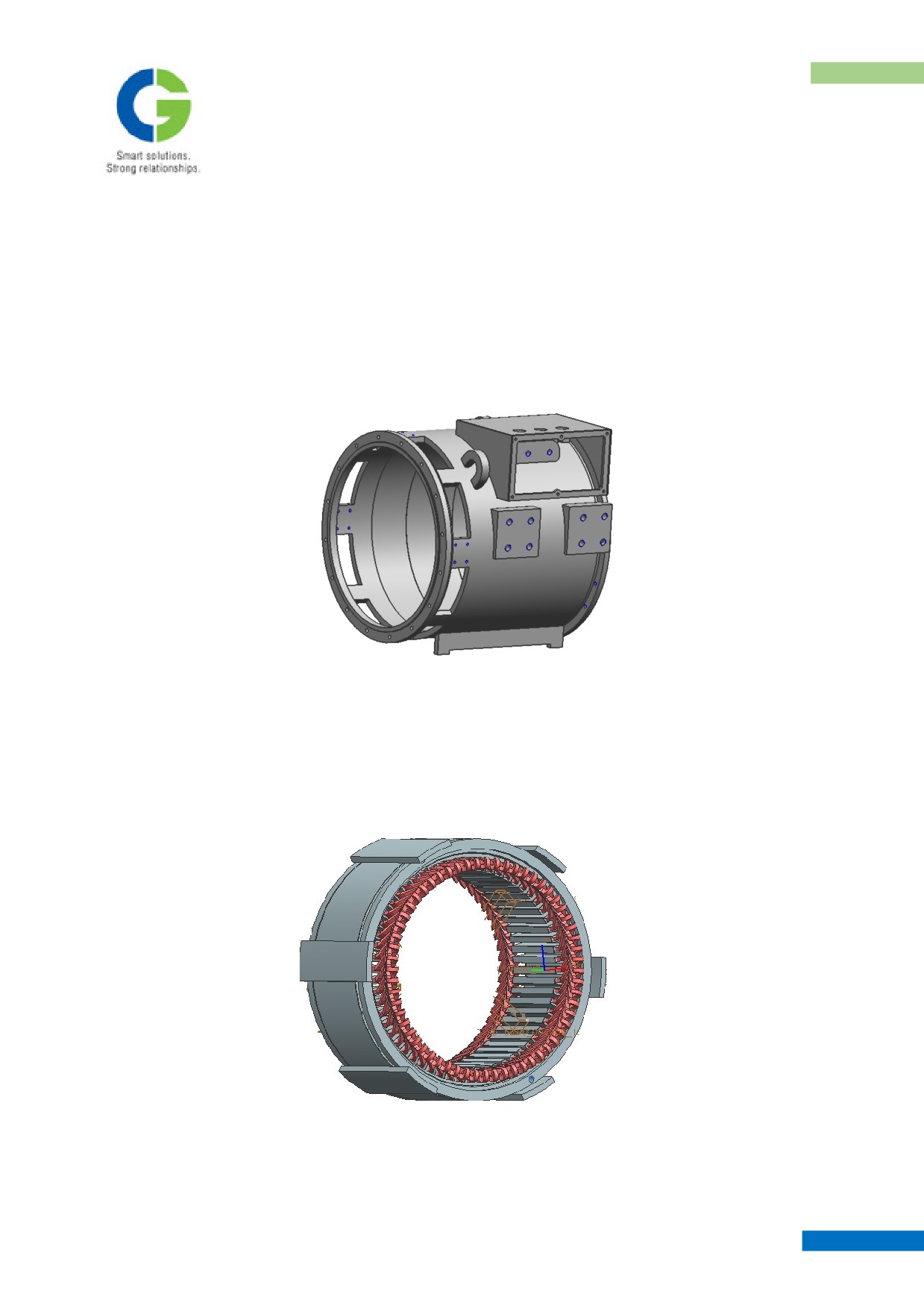
Stator frame along with terminal box is a fabricated structure using mild steel plate. It is designed to ensure
correct distribution of airflow over the Stator core and windings.
Stator Frame
3.1.2 STATOR CORE
In stator core, Stampings stack is supported with mild steel end plates at both ends & reinforced with landing
bars, which are welded with complete stack & both end plates. Stampings are made of silicon steel with C6
coating for proper welding of stack. These punching are oriented to 90° length one fourth resulting in better
magnetic properties.
Stator core with winding
3.1.3 ARAMTURE WINDINGS
MAINTENANCE MANUAL FOR DETC-US
TRACTION ALTERNATOR
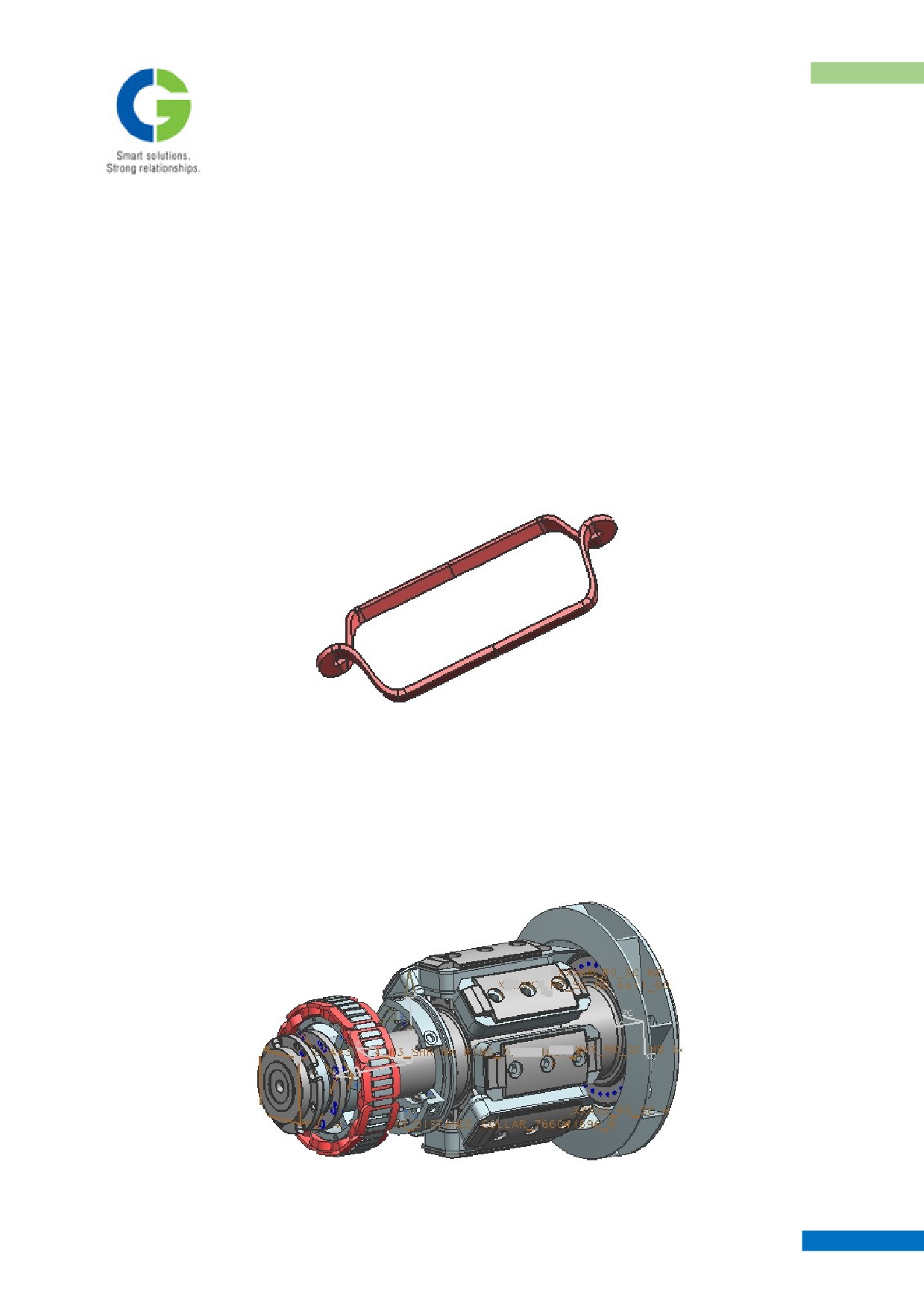
Winding is designed for 8 pole, 3 phase, double layer diamond winding star connected, housed in a open slots,
single turn ( made up of single conductor having no laminations.)
The Connections are made to the phase rings by gas brazing and phase connectors are taken to the terminal
box by means of BUS BAR. The phase rings are properly insulated between line to line and live to earth
parts.
Armature coils are made from polyesterimde enamelled glass lapped Conductor for class 200 suitable for
VPI formed on special formers.
Overhang is properly tied up with the help of resiglass tape to the epoxy bracing ring so that the electrical
and severe mechanical stress in case of any abnormal event can be resisted by the windings. 5th and 7th
harmonics are mitigated by a 60° winding distribution and should not normally be the major target for
reduction by pitching.
Stator Coil
3.2 WOUND ROTOR ASSEMBLY
Rotor consists of shaft, 8 rotor field coils (4 north polarity + 4 south polarity), diode assy, exciter armature.
The rotor is wet wound for eight poles using epoxy compound and properly interlined to have better
resistance to centrifugal force, then locked with support block to have proper locking. The rotor field coils
are vacuum pressure impregnated with solventless resin of class 200.
Wound Rotor Assembly
MAINTENANCE MANUAL FOR DETC-US
TRACTION ALTERNATOR
3.2.1 ROTOR HUB:
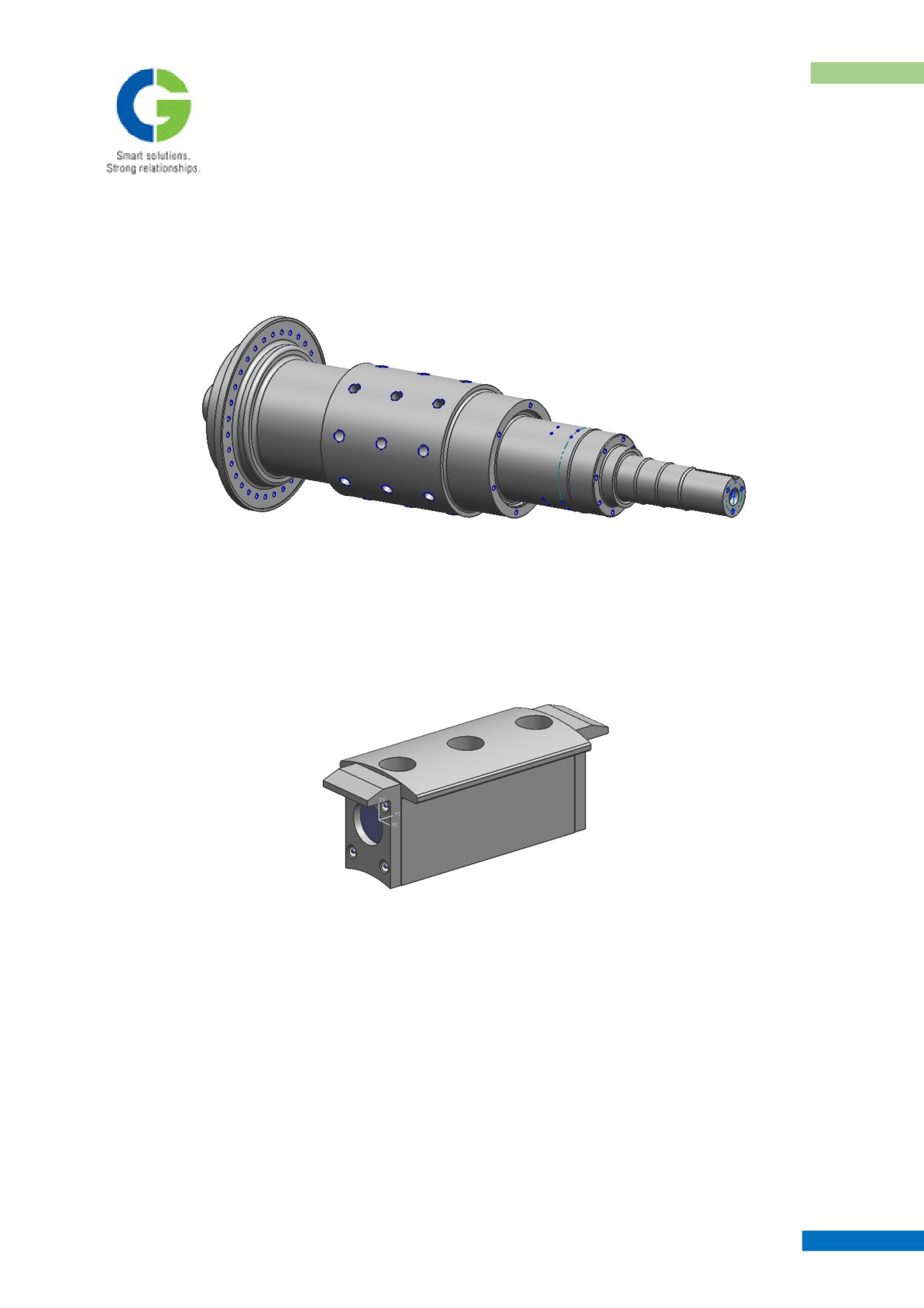
The shaft is made of forged medium-grade carbon steel IS: 2004 CLASS IV. The shaft is liberally designed
for overload conditions. The rotor shaft is forged and ultrasonically tested to give greater reliability in
performance.
Rotor Hub
3.2.2 ROTOR FIELD COILS
Main field pole is built up of high quality, low silicon, steel sheets, oriented to 180° after every one-fourth
length for better grain orientation and better magnetic properties.
Rotor Pole Brick
For forming the rotor field coil, main field pole is directly wound with rectangular copper conductor by wet
winding process using epoxy compound , which gives better insulation properties and mechanical strength.
The coils are formed by winding directly over the pole body to give better rigidity in service and this also
minimises the loosening of poles in service. While assembling the wound poles utmost care is taken during
the production stage. Field coils are fastened to shaft with high tensile steel bolts with specified torque and
locked through tack weld in position.
The coil to coil strap connectors are individually insulated and brazed to the coil leads. The connectors are
held and braced to support plate of diode wheel several layers of Resi-glass tape is applied on the connectors
(live surface) and cured fully to form a rigid connection.
The fully assembled rotor with field coils and connections is subjected to painting with anti-tracking
insulating paint to avoid trapping of moisture and improved electrical properties.
MAINTENANCE MANUAL FOR DETC-US
TRACTION ALTERNATOR
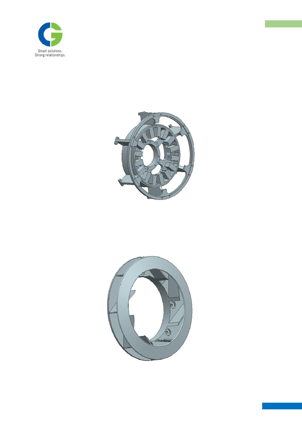
3.3 END FRAME:
End frame is fabricated from thick steel plate construction, Spigot to the stator frame and is fixed by easily
assessable high tensile screws. The end frame supports the exciter winding and bearing assembly. It is so
designed to facilitate the easy accessibility of diode wheel for Maintenance.
End Frame
3.4 ROTOR FAN
The rotor fan is manufactured with special Aluminium alloy. Special care is taken to ensure that the fan is
free from any sort of casting defects. All the fans undergo thorough dye penetration and radiographic testing
for highlighting any surface or sub surface defects.
Rotor Fan
MAINTENANCE MANUAL FOR DETC-US
TRACTION ALTERNATOR
3.5 TERMINAL BOX
This alternator stator is having internally 3 phase star connection, brought to the terminal box bus bars.
Phase bus bars are brazed with phase rings, which are supported on the main frame & properly insulated
from earth. The phase bus bars coming out of the frame are properly supported on steel cleats with Resi-
glass tape to minimise the cable tension. Other end of phase cables is fixed on insulating rod through plated
hardware to maintain minimum air gap (creepage) between live to live & live to earth parts. Single holed
Lugs are provided for output power cable connection. RTD terminals have been terminated at elex elements
supported inside the same terminal box.
3.6 DIODE WHEEL ASSEMBLY
Diode wheel assembly is made up of solid iron plate in which insulation discs are bonded together with resin.
Heat sink are specially designed for speed up to 2500rpm. The rotating diodes are protected by a metal
oxide varistor against voltage surges arising due to fault conditions on load side. Diodes are suitable upto
PIV of 1600 volts, and specially designed for high
`g’ application, 3 positive and 3 negative diodes of
Ruttonsha no.
150LMR is used. Each heat sink is specially designed to accommodate one bridge arm and
output is fed into a common copper connector for all the arms to the rotating field.
Details of rotating rectifier
• Mounted on the same rotor shaft of alternator.
• Support plate is made up of mild steel. Its function is clear form the name given to it
• Heat sink is for carrying out the heat generated in the diodes during their operation
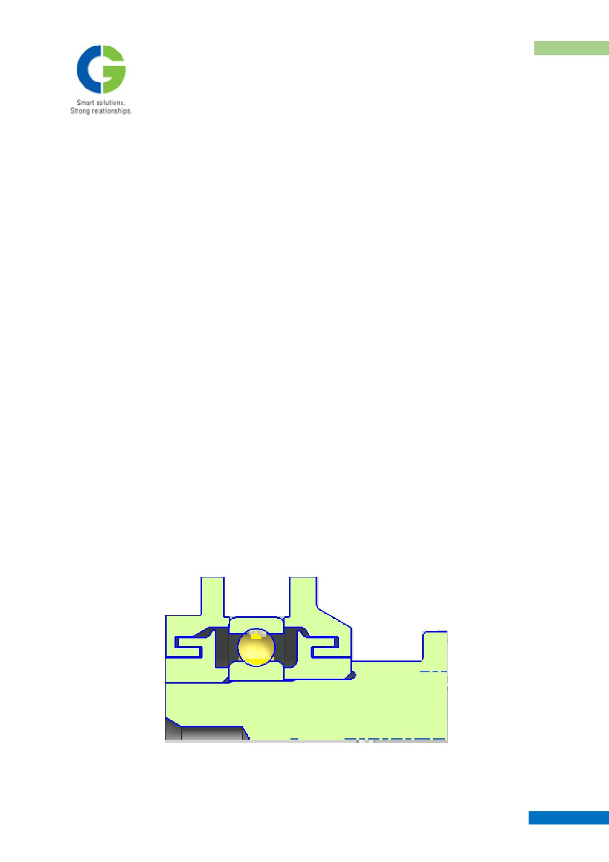
3.7 BEARING ARRANGEMENT
The bearing arrangement consists of inner bearing cap, shrink ring, ball bearing, distance collar, outer bearing
cap. Assembly stages of these parts are as shown in fig. All these bearing components are made of forged
carbon steel as per IS: 2004 class 3 & 4. Self-locating, sealed bearing arrangement has been designed to have
better circulation of grease during service. Grease inlet pipe along with grease nipple (1/4 inch BSP) have
been provide in outer bearing cover for topping up grease during routine maintenance
Bearing Assembly
MAINTENANCE MANUAL FOR DETC-US
TRACTION ALTERNATOR
4. MAINTENANCE SCHEDULE
At the outset, it may be emphasised that the routine maintenance of Traction Alternator is much simpler due
to the absence of Commutator and its brush-less arrangement.
Routine maintenance of Traction Alternator therefore, mainly includes periodic cleaning and inspection of
the machine.
It is recommended that the period of inspection should be more frequent in the initial period of service, and
schedule can be subsequently relaxed based on experience. The periodic maintenance schedule chart
accompanied with this manual should be filled and should be periodically sent back to the manufacturer.
4.1 CLEANING
Clean all the dust and dirt from the exterior of the Alternator, taking special care at the areas around air
opening and inspection covers. Air Inlet cover is removed from the alternator by taking out the M12 hex
head screw. Then only the air inlet cover can be removed and it is advisable to take care for withdrawal of
small M6 screw while opening the assembly. Air inlet net to be cleaned only with kerosene or and other
solvent. Dirt & dust of the alternator is to be cleaned by vaccum cleaner. In absence of vacuum cleaner, dry
compressed air is to be used for cleaning. During cleaning it is to be ensured that dust is blown out of
alternator or air inlet duct whenever compressed air has been applied for cleaning.
Wipe the dust over the diode and insulation disc and approachable parts of the rotor field coils and
connections. Best way of cleaning is to moist a clean lint free cloth with solvent for wiping. Recommended
cleaning solvents are given in Table.
While cleaning, look for any defects, hot spots or abnormalities, for taking corrective action consult with
manufacturer.
4.2 PERIODIC INSPECTION
Periodic inspection should be carried out after thorough cleaning and following points should be given
special attention.
Inspect the diode wheel for any damage of knots of resi-glass and cable holdings. Use glass chord of dia. 1.0
to do the needful as per the perception of operating personal. This is only a temporary solution.
Check machine exciter for any collection of grease leakage from the bearing assy. If the leakage appears to
be significant then end frame covers as shown in a figure are to be removed and the leakage should be
cleaned.
Check the Main Terminal box and Exciter Terminal Box for dust and use blower.
Check bus bars and connections for cracks or frayed insulation, ensuring complete security, of operating
personnel.
Ensure that there are no loose nuts or bolts in the machine and securely close the inspection cover. One
should be Very careful while doing the job on the an side (coupling side)
4.2.1 PERIODIC TIGHTENING OF BOLTS
MAINTENANCE MANUAL FOR DETC-US
TRACTION ALTERNATOR
To be done every month for the following assemblies in addition to routine inspection check, carry out with
specified torque value. Refer maintenance data for values.
Components
Torque (kgm)
Coupling bolts to engine and fan
8-10
End frame to alternator stator frame
8-10
14- 16
Cable connections to Alternator
Main bracket fixing bolts to AVM
69-83
Air inlet covers.
2-3
Replace any cracked spring/lock washer or any damaged bolt and also check locking of the remaining bolts
in rotor if it is taken out for overhauling or for bearing change.
4.2.2 INSULATION CHECK
In every 3 months, check the insulation resistance of the rotor and stator with a 500 Volts Megger and record
the IR value. The Alternator can be safely operated with a minimum hot insulation resistance of 1 to 2 Mega
ohms. Further fall in IR calls for additional cleaning and re-painting with insulating varnish of stator and
rotor. Sometimes the accumulation of moisture in the machine leads to low Insulation Resistance, then the
machine needs prolonged drying at low temperature of 100-110 °C till the insulation improves. Specially
take care of the deposition of dirt and during the first heavy rains of the season.
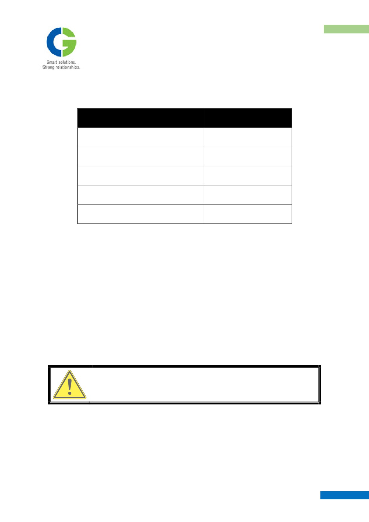
WHILE CHECKING WITH 500 VOLTS MEGGER SHORTENS ALL, AC
& DC BUSBARS TO AVOID DAMAGE TO THE DIODES. REMOVE
THE SHORT AFTER MEGGER CHECK.
4.2.3 RELUBRICATION
50 grams grease (see data for grade) is to be topped up in the end frame bearing assembly only after a year of
service or 150000 Kms of run which ever comes first. . This is to be done in addition to all the above checks.
4.2.4 DIODE REPLACEMENT
In the case of damage/failure in diode, diode of same polarity shall be used for replacement. It is
recommended that the make of diode be only of Ruttonsha for product reliability. After assembly, the
MAINTENANCE MANUAL FOR DETC-US
TRACTION ALTERNATOR
continuity of replaced diode to be checked with multimeter. Diode to be assembled at specified torque value
. For assembly please see the sketches for the detailed assembly.
4.2.5 PERIODIC OVERHAUL
The Alternator is required to be overhauled, even if the same is working satisfactorily. The period of
overhaul can be varied between 4 to 5 years depending on the conditions of operation and maintenance.
However the first overhaul is recommended before completion of 2 years as it is the first of its type in India
and to have the feed back to the manufacturer.
The routine overhaul mainly consists of
• Dismantling & cleaning
• Inspection & reconditioning
• Replacement & reassembly.
4.3 DISMANTLING & CLEANING OF ALTERNATOR:
Before undertaking dismantling Alternator, examine its OGA & PART drawings submitted to the customer
during the approval stage and follow it in presence of experienced personnel or some one from manufacturer
side.
It is recommended that, as far as possible, reassemble after overhaul, the same components, which have been
dismantled from the machine.
For dismantling refer the figure attached and proceed as follows.
Clean the Traction Alternator externally.
After removing the alternator from the Engine, Put the slot wedges provides in the air gap of pole tips in
armature portion so that sudden load is not transmitted to the bearings.
Remove bolts of end frame while alternator is kept vertical bearing side up
Use eyebolt of M20 in the taps provided and lift it with the help of wire sling slowly. As soon as the centre is
achieved the slot wedges will fall automatically to ground. It is to be replaced while making the alternator
horizontal. Use the torque level as specified in the table of technical data.
End frame is a push fit on the frame. There are three tapped holes provided on the 725PCD. Jack with M12
bolts to remove the end frame from main stator frame.
Removing the Outer Bearing cap:
Unlock and remove the bolts for the outer bearing cap and clean with a cotton waste thoroughly.
End frame can be removed from the bearing by keeping the rotor coupling face on the stand and pulling the
end frame with the help of sling. First remove from the frame as mentioned above.
MAINTENANCE MANUAL FOR DETC-US
TRACTION ALTERNATOR
Remove end covers and inserts the puller bolts of M20, tapped at both the ends in the inner bearing cap. On
the other end put the plate with a hydraulic jack to pull the distance collar, bearing, shrink ring together.
4.3.1 CLEANING
All parts of the disassembled Alternator, including bearing, bearing housing is to be thoroughly cleaned
before examination.
Cleaning should be attempted by blowing dry compressed, low-pressure air followed by wiping with clean
lintless cloth. Even a stiff Nylon brush or fibre scrapper may be used. In severe cases cloth dampened with
solvent can also be used.
CHLORINATED HYDROCARBON TYPE CLEANING SOLVENTS ARE
NOT RECOMMENDED FOR USE ON EQUIPMENT BECAUSE OF
POSSIBILITY OF INSULATION DAMAGE
CLEANING SOLVENTS MAY BE TOXIC AND/OR INFLAMMABLE.
TAKE ADEQUATE PRECAUTIONS AS SPECIFIED BY SOLVENT
MANUFACTURES.
Use following cleaners:
a) For insulation: use non-oil quick drying cleaners.
b) For end bearing fits, shafts, metal surfaces use a cleaner which will not leave an oily deposit on
the finished surface.
c) For bearings use cleaner which will not completely remove the oil film from finished surfaces.
Kerosene, petroleum spirit or petroleum solvents are satisfactory.
Cleaning with steam (alternative method).
d) Heat a washing compound in a steam tank (water and cleaning compound) until the temperature
reaches 100 °C.
e) Place the parts to be cleaned in such a position that the steam can be directed from a hose in all
directions for cleaning.
f) Allow clean parts to cool and blow compressed air for removing moisture.
g) For electrical components heat them in oven till the moisture is removed.
4.3.2 INSPECTION AND RECONDITIONING:
After the thorough cleaning of all parts, inspect and recondition as follows:
MAINTENANCE MANUAL FOR DETC-US
TRACTION ALTERNATOR
4.3.2.1 STATOR
After thorough cleaning of stator examine for any loose wedge or damaged insulation or hot spots. If loose
wedge is found replace them with new ones giving proper packing beneath them.
If any damaged insulation is noticed on end winding portions, the same can be locally repaired with glass
mica tapes and glass tapes.
If a hot spot is noticed on the lead joints, remove insulation and examine the brazed joint. If in doubt re-braze
taking adequate protections for surrounding coils by packing wet asbestos putty all around and carry out
torch brazing with silphos brazing alloy strip and rod. Re-insulate after re-brazing. Check insulation
resistance with a 1000 Volts Megger. IR should be greater than 20 M Ohms. H-V test is to be performed at
1kv for one minute.
If IR is found to be less than the specified limit, when alternator was not in use for a long period of time, for
developing the IR, heat the stator in an oven operating at 100 to 110 °C for 6 hours, and check insulation
resistance and continue heating till IR is satisfactory.
4.3.2.2 ROTOR
Check the rotor for any damaged or loose coils by tapping the coils using a wooden mallet. Check rotor field
coil to coil connections for looseness by tapping.
Rotor insulation resistance to be checked with a 500 Volts Megger. If IR value is more than 20M Ohms no
repair is needed to the rotor otherwise it is to be subjected to the following varnish treatment Once again
clean the rotor and the rotor coil surface and blow over the shaft barrel.
Heat the rotor in an oven operating at 100 to 110°C for 6 hours.
Check insulation resistance and continue heating till IR is satisfactory. Rotor - 150M ohms, Exciter rotor
50M ohms.
When the rotor is above the room temperature, apply two bricks coats of solvent less resin, all over the rotor
pole coils, pole body face and connections ring.
Rotor to be cured at 160
c for 10 hours.
Once again check IR value it should be greater than 40M Ohms.
Apply anti tracking insulating varnish and then rotor is to be cured at 160
C for 6 hours
FIELD CONNECTOR REPLACEMENT:
If any field connector or stator overhang is to be replaced or repaired due to damage or failure, follow the
procedure as below:
Cut the Resi-glass binding Tape on the field connector ring at the affected pole coil and remove Resi-glass
tape to the extent required. Un braze the coil to coil connector and if the coil to coil connector is damaged,
replace it with a fresh one, while replacing ensure the connections are made according to the diagram. See
Fig. Stator connection diagram. The bare connector is to be insulated as below:
MAINTENANCE MANUAL FOR DETC-US
TRACTION ALTERNATOR
-
One layer half lapped with 0.13mm x 19mm wide kapton mica tape.
-
Followed by one layer half lapped 0.038mm x wide P.T.F.E tape.
-
Followed by one layer half lapped 0.10mm x 25mm wide Glass tape.
-
On the lead to lead insulation between poles use one layer of kapton mica, one layer half lap of
glass mica, one layer half lap of glass tape used above.
-
Double the above quantity for stator overhang and 3cms on either side of damaged area.
The Resi-glass taping requires curing at 135 °C for 6 to 8 hours and the entire connector ring portion is to be
resin treated as mentioned in` rotor reconditioning. During this process remove the diode heat sink as it is not
designed for such a high temperature.
RECONDITIONING OF ROTOR FIELD COIL
REPLACEMENT:
If a particular rotor coil is to be dismounted, adopt the following procedure:
a) Mounting of field coil on rotor.
1.0 Place rotor vertically (Bearing end up)
2.0 Open coil to diode wheel connections.
3.0 Unlock and open mounting bolts.
4.0 Remove the coil support by hammering the wedge.
5.0 Isolate the faulty coil leads by removing the insulation and de brazing the joints.
6.0 Remove the tack weld of the mounting bolts.
7.0 Hold pole and coil assembly with a Nylon sling and open pole bolts. Torque required will be
around 80 kg-m.
8.0 As pole is directly wound on pole the whole new assembly. Pole is to be replaced in case of
faulty pole. Pole is subjected to VPI after forming and consolidation with epoxy resin.
9.0 Check the IR value of the coil it should be more than 150 mega ohms.
MOUNTING OF FIELD COIL
Clean pole body and paint with anti-tracking insulating varnish.
Hold pole assembly vertically up and bring near to shaft barrel. Assemble with pole bolts. Conduct HV test
on changed coil at 1.0kV for one minute and then tighten pole bolts with specified torque and tack weld to
lock it.
MAINTENANCE MANUAL FOR DETC-US
TRACTION ALTERNATOR
TORQUE IT WITH 80 KG-M
BOLTS M24, CLASS 12.9
LENGTH 140 mm
DO NOT INTER CHANGE ROTOR STRIPS PLACED BELOW THE
EACH POLE WITH ONE ANOTHER. AS THIS GOVERNS THE ROTOR
DIA VARIATION.
After the field coils are installed, the coils connections are to be completed and the rotor needs to be resin
treated in line with the instruction under reconditioning.
Dynamically balance rotor, after the final assembly of diode wheel components. Balance weight can be
added on support plate and on coupling face where provision is specially made for this. Balancing should be
done at 1100 rpm within 5 GMS of residual unbalance.
4.3.2.3 BEARING COMPONENTS
Examine outer bearing cap, shrink ring, bearing cap for any dents, score marks. If they are of minor nature
attend with a oil stone and rinse. If the damage is considerable same are to be replaced with new
components.
Examine the followings:
1. Flaking or cracks in the ball path. If found, reject the Bearing.
2. Heavy electrical pitting. If found, reject the bearing.
3. Raised craters around the edges. Stone off (do not file).
4. Mottled distributed pattern of dirt denting. Scrap the Bearing.
5. Evidence of rubbing or turning on the shaft. Look for loose Spacers or interference of the
housing parts. If rubbing is Heavy or if there is wear on the shaft, reject the bearing.
Examine the outer race as follows:
Slide the outer ring by hand and if the ball drags, scrap the bearing.
Scrap the bearing if any of the following conditions are discovered on any of the bearing parts.
1.
Severe scoring caused by inadequate lubrication.
MAINTENANCE MANUAL FOR DETC-US
TRACTION ALTERNATOR
2.
Corrosive pitting caused by moisture or electrolytic action.
3. Break or crack (possibly caused by striking the shafts with a hammer during removal).
4.4 REASSEMBLY OF TRACTION ALTERNATOR
1. Fit the distance collar onto the shaft, if removed, ensuring that it is solidly up to the shaft abutment
face.
2. Fit the bearing by heating it to 100 to 110 °C and shrinking onto the shaft (if already removed),
when cold. Tap the race to ensure that it is solidly up to shaft abutment face. Put identification marks
on both the distance collar and shrink ring.
Rest of the procedure to be followed in reverse as described in clause no
9.1, and of course any other best practices can also be adopted depending
on the requirements.
STANDARD REFERENCE CONDITIONS
TEMPERATURE
These alternators are designed for an ambient temperature of 55°C. For marine and other applications where
the ambient temperature is greater than 55 °C, the alternators must be derated to ensure that the actual
temperature does not exceed the specified maximum, Outputs are normally quoted at 55 ° C. These outputs
must be multiplied by the following factors for higher ambient temperatures.
TEMPERATURE
MULTIPLIER
(°C)
60
0.95
ALTITUDE
Above 1000m the effectiveness of the air is reduced sufficiently to make derating necessary. For altitudes
above 1000m outputs must be multiplied by the following factors.
MAINTENANCE MANUAL FOR DETC-US
TRACTION ALTERNATOR
ALTITUDES
MULTIPLIER
1,500
0.97
2,000
0.94
2,500
0.91
3,000
0.88
3,500
0.85
4,000
0.82
HUMIDITY
Machines are tropicalised and can successfully operate in high humidity levels. Correct choice of the
insulating materials and careful assessment of the impregnation varnish system and methods achieve this.
5. ALIGN MENT PROCEDURE OF ALTERNATOR WITH DIESEL ENGINE
1. Rotate the engine freely one or more round complete before alignment.
2. Check the engine crankshaft endplay and note down the end play (x). This should be measured with help
of dial bore gauge. Once the measurement is done keep the crankshaft towards vibration damper end.
3. Check the TIR(Total Indicative Reading) of flywheel housing. The check is mandatory if the engine was
taken for rebuild and housing was removed.
4. Record dimension “a” by using vernier calliper.
5. Apply little grease on flywheel pilot bore, as the rotor slides in the pilot bore during assembly as a guide.
Preparing the alternator for alignment: -
1. This alternator being a single bearing alternator Never ever attempt to rotate the alternator rotor when it is
in uncoupled condition as this may damage the windings of rotor/ stator. Alternator is shipped with rotor
locked by shipping bracket.
2. Remove the shipping bracket and mount the flex plates comprising of 8 nos.(1.2 thk) on the rotor by 8 nos
hex head bolts M20X55 long and torque them to 100 lb-ft torque. Engage alternator fan with outer diameter
of coupling.
MAINTENANCE MANUAL FOR DETC-US
TRACTION ALTERNATOR
3. Place the hand-operated jack properly to lift up the rotor and measure the distance between the rotor and
stator frame. This should be considered to be accurate when measurement in all the directions is equal. This
exercise should be made with a view to make the rotor shaft horizontal to axis of the alternator/rear bearing.
4. Now measure the endplay of rotor by playing the rotor shaft
from rear end, note this play as “y” and
finally keep the rotor pushed to the rear end.
5. Measure the dimension “b” with the vernier calliper and note.
Dim “a” stand for distance between alternator stator spigot face &
flex plate face, which is fixed on rotor shaft.
Dim “b” stands for distance between engine adopter spigot face &
flywheel face.
Shim selection:
1. if a> b then add up the shims between flex plate & Rotor shaft. These shims must have
thickness as, 0.1 mm, 0.25 mm, 0.5mm, 1.0mm, and 1.6mm.
2. Thickness of shims to be added :- (a-b) + (x+y)/2
3. Choose the thickness of shims nearest in multiples of 0.1mm so that both rotor and crankshaft
are at the centre of the travel in their bearing.
4. Two studs 5/8” unc x 100 mm long are to be fixed diagonally opposite in flex plate mounting
hole of engine flywheel.
5. Move/Tilt the alternator to locate studs that are fixed in flywheel, visibly with the holes in flex
plate.
6.
16 nos socket head cap screws M16X70mm to be used for holding stator frame of alternator
with adopter plate of engine with standard bolt tightening practice (diagonally opposite bolts).
7. Cummins supplied 2 nos out of 8no’s hex head bolt 1/2” unc x 3.5 inch to be inserted through
alternator fan, flex plate to flywheel. These bolts are to be partly tightened.
8. Both the studs are taken out safely through alternator fan.
9. Remaining all the 10 bolts are to be placed at vacated fixing locations. All the 12 bolts are to
be tightened at specified torque value followed by the standard tightening practice.
MAINTENANCE MANUAL FOR DETC-US
TRACTION ALTERNATOR
After assembly of alternator match the load characteristics.
If there is an abnormal change in the characteristics, then
attention is to be paid on the root cause.
6. PROTECTION OF BALL ROLLER BEARINGS
6.1 GENERAL
The ball bearing incorporated into CG Traction machines is of high quality and adequate capacity as
supplied by the leading bearing manufacturers. Every care is taken during assembly to ensure that
the correct fitting-tools are employed, and strict cleanliness observed, to achieve long and trouble-
free operation of bearings in service.
It is essential that equal care is taken of bearings, which may be subject to removal and replacement
during normal overhaul procedures, and of new bearings to be fitted when renewal is necessary.
Bearings seldom break down as a result of normal usage; the most common causes of bearing failure
can be traced to mishandling, damage or stress set up during fitting or removal, dirt, corrosion, and
over or under lubrication.
ALWAYS CLEAN BEARING COVERS, CAPS AND HOUSINGS BEFORE
REMOVING BEARINGS, AND USE CORRECT WITHDRAWAL AND
REFITTING TOOLS.
The following information is a general guide to the care and use of roller bearings. More detailed
literature is obtainable from the appropriate bearing manufacturers.
6.2 FITTING AND REMOVING BEARINGS
1) The use of a press or extractor is preferable than to a hammer and drift whenever possible. It is
also preferable to immerse bearing in oil at a temperature of 100 °C for 25-30 minutes, or place in an
oven under the same conditions.
2) If it is necessary to hammer the tool when removing a shaft nut or bearing retaining nut, always
firmly support the shaft, to avoid shock-loading the rolling elements or races.
3) Never strike a bearing directly with a hammer; a mild steel or brass drift or tube should be
interposed between hammer and bearing. The end of the drift or tube in contact with the bearing
should be squared off and free from burrs.
4) Check bearing housings for signs of race creepage.
MAINTENANCE MANUAL FOR DETC-US
TRACTION ALTERNATOR
5) When using presses, extractors or drifts for the fitting/removal of bearings it is essential that no
load be transmitted through the rolling elements of the bearing.
6.3 INTERCHANGEABILITY OF BEARING COMPONENTS
Roller bearing components must not be inter changed.
NOTE: Bearing failure can occur as a result of accidental or indiscriminate interchanging of bearing
components. The component parts of individual bearings must be kept together at all times and not
mixed with other, similar, bearings and bearing components.
6.4 CLEANING AND ANTI-CORROSION TREATMENT
A. General Treatment
Avoid the temptation to spin a bearing after it has been removed from an assembly, and before
cleaning; this is to avoid compressing hard particles, which may be present in the lubricant, thereby
initiating track defects.
B. Bearings which should not be cleaned
Do not clean bearings, which are to be returned to the manufacturer for defect examination; such
bearings should immediately be wrapped in grease-resisting paper and boxed.
C. Cleaning the bearings
The importance of cleanliness when dealing with bearings cannot be too highly emphasised. The
parts must be scrupulously clean to enable accurate assessment of serviceability to be made and, if
found to be serviceable, it is of equal importance that they be maintained in a clean condition for
subsequent build into the assembly.
To minimise the risk or corrosion by handling, it is recommended that, so far as is possible,
operators should wear protective gloves during and after the cleaning process.
Bearings or components incorporating bearing surfaces, must in no circumstances be left in a dry
condition, or unprotected against corrosion.
Tri-chloro-ethylene, carbon tetrachloride, or paraffin should not to be
used for cleaning bearings, as any of these agents can promote corrosion.
D. Cleaning Equipment
Where large numbers of bearings are to be processed it may be advisable to provide separate
cleaning, rinsing and inhibiting tanks of a size appropriate to the volume of work. Each tank may be
MAINTENANCE MANUAL FOR DETC-US
TRACTION ALTERNATOR
constructed of mild steel and should be equipped with a drain plug. Wire mesh baskets or platforms
should be provided to hold the bearings clear of sediment in the bottom of the tank. The inhibiting
oil tank should be heated to 90 ° to 100 °C (194 ° to 212 ° F).
1) Initial cleaning tank
The tank should contain an adequate quantity of white spirit / gasoline and should be drained,
cleaned out, and refilled with fresh liquid whenever approximately 100 bearings per gallon of liquid
have been processed, or when excessive contamination is suspected.
2) Second-wash tank
Also to contain white spirit / gasoline and to be topped up with fresh, clean liquid to replace drag-out
losses.
3) Inhibiting oil tank
The tank to contain inhibiting oil such as shell Ensis 100.
4) Mineral jelly tank
The mineral jelly must be maintained at 80 ° to 90 °C
(176 ° to 194°F) and be periodically topped
up to replace drag-out losses.
The tank should be cleaned out and refilled with fresh mineral jelly whenever contamination is
suspected.
E. Cleaning and temporary inhibiting
To minimise the possibilities of corrosion on the bearing surfaces during cleaning and subsequent
inspection, it is recommended that bearings should not remain unwrapped for more than 4 to 5 hours
while temporarily inhibited. Bearings should always be immersed in a horizontal position in the
cleaning and inhibiting fluids to avoid the retention of air pockets. Rotate the bearings during the
cleaning operation.
The following sequence of operations is recommended and should be carried through with the least
possible delay between each
operation.
1) Wash the bearings in the initial wash tank using a bristle brush to remove all dirt or old lubricant.
2) Remove the bearings from the wash tank and allow draining for 5 minutes.
After the initial wash, carbonised bearings may be soaked in hot mineral
oil (90 ° to 100 °C, 194 ° to 212 °F); agitating the bearings slowly, from
time to time. Badly carbonised bearings may be cleaned in a strong
alkaline solution; see the appropriate manufacturer's instructions.
MAINTENANCE MANUAL FOR DETC-US
TRACTION ALTERNATOR
3) Completely immerse and wash the bearings in the second wash tank.
4) Remove the bearings from the tank and allow draining for 5 minutes.
5) Immerse the bearings in the inhibiting oil tank for temporary protection against corrosion.
6) Remove the bearings from the oil and allow thoroughly draining and cooling in still, dry, dust free
air.
At this stage, the bearings should be examined for Defects; however, if
some delay between cleaning and examination is unavoidable, the
components should be wrapped in grease resisting paper.
F. Treatment of new bearings
New bearings should not be removed from the package until immediately before fitting. It is
preferable to remove the preservative from the rolling members and race surfaces by immersion in
the inhibiting oil tank as in E5 and 6.
G. Treatment after inspection
After inspection, again wash and inhibit the bearings as described.
If the bearings are not immediately required for fitting they must be wrapped in grease-resisting
paper or unsealed polythene envelopes. Bearing may be stored in this condition for up to 14 days.
Bearings to be stored for longer periods should be treated as follows: -
1) Totally immerse the bearings in the mineral jelly tank for approximately 10 minutes.
2) After cooling, dip the bearing a second time into the mineral jelly, remove immediately and wrap
the bearing In grease-resisting paper. Store in a dust tight box.
6.5 INSPECTION
After cleaning, bearings should be thoroughly inspected together with associated components, such
as seals. The housings and shafts from which the bearings have been removed should also be
examined. Thoroughly examine each bearing for visual defects such as rust and discoloration,
cracks, wear, indentations and bruising, and track defects. Bearings associated with electrical
machines may sometimes be found to contain craters or pits caused by electrical arcing. The craters
will
have a centre of black, fused, metal. Unless the damage to the rolling element or track is
slight, bearings should be rejected.
A.
Rust and corrosion
MAINTENANCE MANUAL FOR DETC-US
TRACTION ALTERNATOR
Rust on the rolling elements is not acceptable and the bearing should be rejected. Very light
corrosion pitting on the races may be accepted, depending upon the speed and loading of bearings.
B. Discoloration
Slight discoloration of the rolling elements or tracks is acceptable, but if the components turn blue or
brown, indicating excessive heat, the bearing must be rejected.
C. Cracks and fractures
In all cases, the bearing must be rejected
D. Flaking
Flaking appears when fragments of material have broken away from the bearing track. Subsequent
wear in the bearing due to increasing stresses is accelerated. Then bearing must be rejected.
E. Smearing
Smearing is the result of the balls or rollers sliding rather than rolling in relation to the tracks ocage,
causing incipient seizure. The bearing should be rejected.
F. Wear
Excessive wear does not occur during normal operation of the bearing. It is generally the result of
misuse in fitting, external vibration when the machine is stationary - causing local shock-loading via
the rolling elements of the bearing, or the ingress of dirt, inadequate or incorrect lubrication is also a
contributory factor.
Non-operating surfaces
(a) Light rust may be removed with fine abrasive cloth, and the bearing thoroughly re-washed as
described Shafts and housings The shafts and housing associated with bearings undergoing
inspection should be examined for defects. Pick-up or scoring on surfaces, which make contact to the
bearing must be rectified by stoning or dressing.
Surfaces, which are worn below the drawing limits, should be built up if possible or the shaft or
housing renewed.
MAINTENANCE MANUAL FOR DETC-US
TRACTION ALTERNATOR
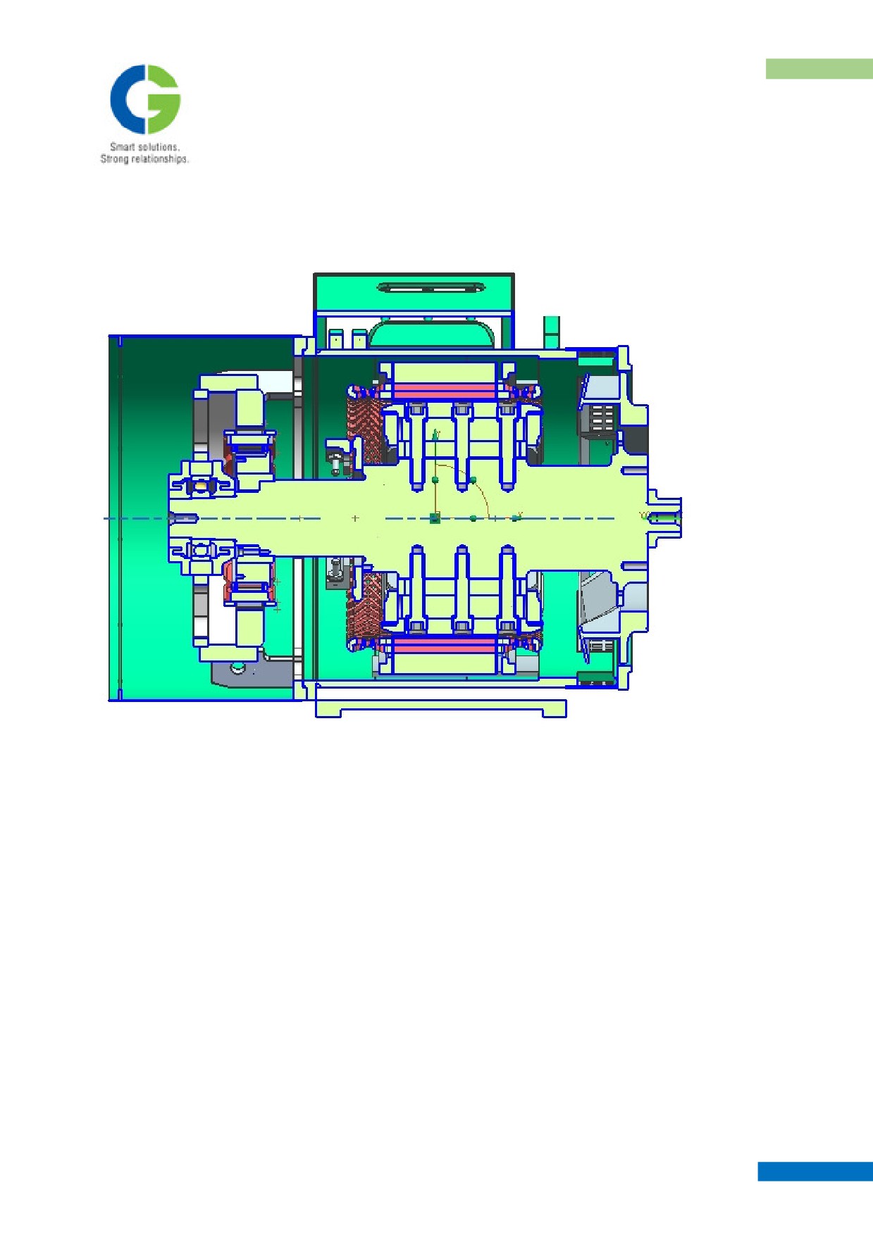
7. LONGITUDINAL SECTIONAL VIEW
Longitudinal section of Traction Alternator
MAINTENANCE MANUAL FOR DETC-US
TRACTION ALTERNATOR
NOTES
-----------------------------------------------------------------------------------------------------------------------------------
-----------------------------------------------------------------------------------------------------------------------------------
-----------------------------------------------------------------------------------------------------------------------------------
-----------------------------------------------------------------------------------------------------------------------------------
-----------------------------------------------------------------------------------------------------------------------------------
-----------------------------------------------------------------------------------------------------------------------------------
-----------------------------------------------------------------------------------------------------------------------------------
-----------------------------------------------------------------------------------------------------------------------------------
-----------------------------------------------------------------------------------------------------------------------------------
-----------------------------------------------------------------------------------------------------------------------------------
-----------------------------------------------------------------------------------------------------------------------------------
-----------------------------------------------------------------------------------------------------------------------------------
-----------------------------------------------------------------------------------------------------------------------------------
-----------------------------------------------------------------------------------------------------------------------------------
-----------------------------------------------------------------------------------------------------------------------------------
-----------------------------------------------------------------------------------------------------------------------------------
-----------------------------------------------------------------------------------------------------------------------------------
MAINTENANCE MANUAL FOR DETC-US
CHAPTER VI
POWER RECTIFIER
1. BRIEF SPECIFICATIONS
2. FUNCTION OF THE RECTIFIER UNIT
3. DESCRIPTION OF THE RECTIFIER UNIT
4. PRE INSTALLTION CHECKS AND COMMISSIONING
5. MAINTENANCE
6. LIST OF COMPONENTS
Maintenance Manual
DIESEL ELECTRIC TOWER CAR | UNDER SLUNG TRANSMISSION
POWER RECTIFIER
CHAPTER VI
POWER RECTIFIER
1. BRIEF SPECIFICATIONS
The Rectifier Unit Conforms to Crompton Greaves Specification No. TE 10002 R0 27.05.2016 and ICF
specification ICF/MD/SPEC - 300 R0 DATED 16-04-2016 as per following brief specifications.
1. Rectifier Type
:
3 Phase Bridge type
2. No. of Bridge in Parallel
:
Three Nos.
3. Max. continuous current
:
750 Amps. D.C.
4. Max. one hour rating
:
1000 Amps. DC
5. Starting Max. current for 5 Min
:
1200 Amps. D.C.
6. Max. output voltage
:
900 V.D.C.
7. Max. Ambient Temp.
:
47°C
8. Cooling
:
Forced Air
9. Cooling Blower Supply
:
110 Volts D.C.
10. Mounting of Rectifier
:
On Board
11. Dimensions mm. (H x L x W)
:
1695 x 800 x 450 without side panels
12 Weight
:
330 Kgs. Approx
The On-Board mounted Rectifier Unit has been designed to feed the Traction Motor load of the 700 HP DETC.
It has been designed to work on 660 Volts max, 3 Phase, 3 Wires AC Input supply derived from underslung
alternator. The Rectifier Unit has been designed to withstand shocks and vibrations encountered in service of a
rolling stock. It rectifies the three-phase AC voltage into a DC voltage. The equipment meets the requirement of
IS: 7788.
2. FUNCTION OF THE RECTIFIER UNIT
The function of the Rectifier is to convert a three-phase supply into DC Voltage, for driving Traction Motors
connected in parallel across the Rectifier. Each of the three bridges are protected by Semiconductor grade Fuses
at the input. In case of a diode failure, the particular bridge is isolated by its fuses. The other two bridges
continue to supply the full load current to the Traction Motors. Hence, n-1 redundancy is built-in. Each of the
Main fuses have a smaller fuse called trip-fuse connected across it. When the Main fuse blows the fault current
is diverted to these trip fuses. These in turn clear the fault current and in the process operate a plunger, which
hits a Micro-switch. This condition stays latched and can be reset only by replacing the Main Fuse and the Trip
Fuse. The potential free N/O & N/C contacts of the Micro switches in turn operate a Contactor to give an
indication in driver’s cabin that a Fuse has blown. In a similar manner failure of a second bridge is indicated by
the operation of a second Contactor. In this condition the Control Circuit of the DETC must reduce the
maximum load current. A single bridge will no longer be able to carry the full load current of the Traction
Motors. Suitable corrective action must be taken. The Rectifier is protected at the input and the output by
suitable Damping Circuits.
The Rectifier is cooled by forcing air through the fins of the Heat Sink. Force cooling is achieved with the help
of a Axial fan arrangement. The Axial Fan operates from 110 VDC Auxiliary Power Supply. The fan, while
working, generates a positive pressure inside its casing. This pressure is sensed by a Pressure Switch. In case of
MAINTENANCE MANUAL FOR DETC-US
POWER RECTIFIER
failure of the Axial fan this pressure will drop and is sensed by the Pressure Switch and the information is
transmitted to the Control Circuit through its NO & NC potential free contacts.
3. DESCRIPTION OF THE RECTIFIER UNIT
The Rectifier has an AC Input and the DC Output terminals are on front bottom side. The Fan draws air from
the engine compartment from top and pushes down through the fins of the Heat Sink and is discharged to the
atmosphere through bottom floor.
The side panels of the rectifier unit are made of MS with backup of FRP sheet on inner side for creating higher
creepage path with live terminals of the unit. These are bolted to main frame.
AC & DC Power Terminals (busbars) are accessible by opening front lower panel and Auxiliary Terminal
Board and CT & PT Terminals are accessible by opening rear lower panel.
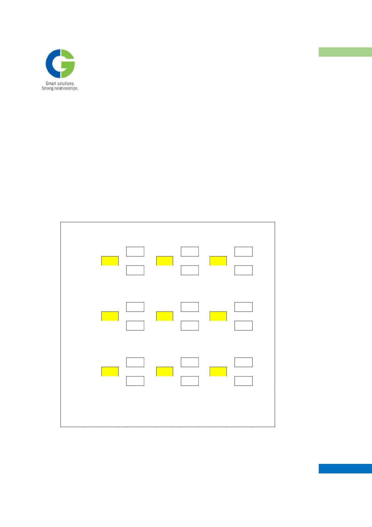
The Diodes and Fuses are accessible by removing front upper panel. The arrangement is as shown below.
D10
D11
D12
FR1
FY1
FB1
BRIDGE - 1
D1
D2
D3
D4
D5
D6
FR2
FY2
FB2
BRIDGE - 2
D13
D14
D15
D16
D17
D18
FR3
FY3
FB4
BRIDGE - 3
D7
D8
D9
Diodes D1 to D9
- Type OSD 595 N36SQ (With Red cover sleeve)
Diode D10 to D18
- Type OSD 595 P36SQ (With Blue cover sleeve)
FR - Fuses 725 A, 1000 V
MAINTENANCE MANUAL FOR DETC-US
POWER RECTIFIER
4. PRE INSTALLTION CHECKS AND COMMISSIONING
4.1 RECEIPT INSPECTION
To facilitate transportation, the rectifier unit should be packed thoroughly in wooden crate. On receipt the crate
shall be checked for any damage. Any visible sign of damage should be reported to us. After unpacking check
the unit internally & externally for any visual damage. Any damage if found, should be reported to us.
During the period of unpacking and inspection it must be seen that the unit is not damaged. After unpacking
Insulation Resistance and HV Breakdown tests may be performed if necessary.
4.2 INSTALLATION
The Rectifier Unit should be lifted and placed in position using the 4 lifting eyebolts that fitted on top side of the
unit. Rectifier Unit should be fixed by the 4 mounting bolts and nuts.
Then connect
a. Input and output cables to the respective terminals
b. 110 VDC supply and Control cables to the control terminal board
4.3 COMMISSIONING
The unit must be subjected to routine checkup including checking of the relevant connections. One has to go
through the technical particulars and general feature sections. After checking all the details the Rectifier Unit is
ready for use.
Before applying Main AC Power to rectifier, following procedure to be followed.
Axial Fan: The fan speed has been set to give required air flow through rectifier heatsink duct. However it
should be checked for air flow from 90 VDC to 125 VDC supply. A potentiometer control has been provided to
set fan speed. It can be accessed by opened by removing left side panel.
The fan speed should be set such that at 90 VDC supply it gives minimum 5 mts./sec air velocity through
rectifier heatsink duct and should not trip at 125 VDC because of its internal O/L trip mechanism.
Now unit can be energized with 3 Phase AC Supply.
Initially the load may be at half the value for few hours. Check all the components and joints for any abnormal
heating or temperature rise or failure. The Load may be gradually increased, in steps till full load is reached. It
is suggested to report any abnormal behavior to the manufacturer.
MAINTENANCE MANUAL FOR DETC-US