8 WHEELER DIESEL ELECRIC TOWER CAR WITH UNDERSLUNG TRANSMISSION. OPERATING & MAINTENANCE MANUAL (2019) - page 1

DOCUMENT TITLE
OPERATING & MAINTENANCE MANUAL
8 WHEELER DIESEL ELECRIC TOWER CAR WITH
PROJECT
UNDERSLUNG TRANSMISSION
CUSTOMER
DIESEL LOCO MODERNISATION WORKS PATIALA
CG Power & Industrial Solutions Ltd.
Issued By
TRACTION MACHINES DESIGN DEPARTMENT, CG
Doc. Ref. No.
CGPISL/DETC_US/MM/01
Prepared
00
Date
31ST JAN 2019
Approved
PREFACE
This instruction book covers the operation & maintenance instructions for electric traction
equipment supplied by Compton Greaves Ltd. to Integral Coach Factory, Chennai for DIESEL
ELECTRIC TOWER CAR WITH UNDER SLUNG DUAL POWERPACK & AC/DC
TRANSMISSION SYSTEM for Indian Railways.
The purpose of this instruction manual is to familiarise maintenance personnel with the
procedures for operating and maintaining the electrical equipment.
This manual covers description of electrical circuits, general maintenance and data on control
gear, electrical machines besides other general information. Instructions for auxiliary alternator,
power rectifier are covered in separate manuals.
The instructions contain adequate details/information required for maintenance of equipment.
Nevertheless, it is not practicable to cover all details and every contingency, which is likely to
arise in service. Should any further information be desired or should particular problem arise, the
matter should be referred to: CG POWER AND INDUSTRIAL SOLUTIONS LTD. Industrial
Systems; D-5 Industrial Area, Mandideep, Bhopal - 462 046.
Continuous efforts on improvement in product design may result changes in details, which may
not be covered in this manual. Although efforts are made to furnish all such changes to the user,
it is advisable to consult CG for obtaining necessary assistance.
CG POWER AND INDUSTRIAL SOLUTIONS LTD.
TRACTION MACHINES & SYSTEM DIVISION,
D-5, INDUSTRIAL AREA, MANDIDEEP
BHOPAL - 462 046
CHAPTER I
INTRODUCTION
1.0 PERFORMANCE AND GENERAL DATA
2.0 LIST OF ABBREVIATIONS
Maintenance Manual
DIESEL ELECTRIC TOWER CAR | UNDER SLUNG TRANSMISSION
POWER PACK ARRANGEMENT
CHAPTER I
INTRODUCTION
This manual covers operation & maintenance instructions of major power & control equipment used in
Broad Gauge Diesel Electric Tower Car with Under slung transmission system (DETC/US). The
equipment meets the requirements of ICF’s spec. No. ICF/M/D/SPEC-300, for supply of complete
electrics of DETC/US. The equipment includes Diesel Engine, Traction Alternator, power rectifier,
traction motors, Auxiliary Alternator, motor switch group cubicle, all protective devices, and instruments
for measurement & indication and auxiliary equipment.
DETC/US is a self-propelled unit used for periodic inspection, patrolling and maintenance of Over Head
Electric Transmission Equipment of Electrified Routes. It is also used for attending sites of break down,
restoration of damaged OHE equipment.
DETC facilitate the breakdown sites by restoring the damaged OHE. It is required to -
a) Reach the breakdown site in shortest possible time,
b) Attend & clear the Traction Over Head Equipment breakdown site,
This whole operation is to be accomplished in shortest possible time with least hindrance to regular rail
traffic.
This is achieved by DETC, with following major facility -
i.
To carry auxiliary equipment to facilitate OHE breakdown.
ii.
Supervisors / attenders seating room and kitchen.
iii.
Installed with high speed Dual Traction Power Pack & its controls.
iv.
Driver desk & control cubicle on either side of the car.
v.
Elevating Platform & Observation Dome.
vi.
Pantograph for testing Over Head Cables.
vii.
Room for OHE testing Equipment & Work shop.
viii.
Tools & tackles to attend / clear the accident site
MAINTENANCE MANUAL FOR DETC-US
POWER PACK ARRANGEMENT
These power packs provide traction power to run the car unit (DETC) at high speeds up to 110 km/h. The
under slung power pack free up the over board floor space for housing supervisory staff & to carry
auxiliary equipment
Each power pack consists of following major components:
1.
Under floor mounted:
•
Diesel engine
•
Traction Alternator
•
Auxiliary Alternator
•
Drive shaft for aux. alternator
•
Exhaust Silencer for diesel engine
•
Water Rising Apparatus for radiator
2.
Equipments installed over board;
•
Control cubicle.
•
Driver's desk.
•
10 KVA capacity Diesel Alternator Unit.
•
Air filters for diesel engine air intake.
•
Hydraulic Oil Tank.
3.
Over the roof
•
Hydro Static Radiator Unit.
•
Elevating platform
•
Pantograph
•
Observation dome
Above equipment with associated accessories are engineered to provide trouble free traction power with
in built safety & protection equipment. The controls are developed to provide regulated traction power to
match the demand from driver's console command while maintaining the safety checks all the time
during traction.
MAINTENANCE MANUAL FOR DETC-US
All the healthy, operation & faults are brought to driver's console as indicating lamps for easy recognition of
sequences happening in the traction system. A fixed time alarm (warning hooter) is also operated to alert the
driver in case of any faulty / warning system activity.
Certain serious system faults not only indicate & warn the driver and also disable the traction power or shut
down the diesel engine depending on the severity of the fault. Under such circumstances, there are certain
"bypass safety" switches provided in the control cubicle. The use of these will enables the driver to run the
traction system for short durations to clear the track for regular traffic.
The bypass safety function is not permitted to use on a regular basis or
for longer periods. Use of bypass safety function for longer periods
could lead to severe damage to the equipment or total failure of the
affected unit connected equipment and severe injury or loss of life,
because the bypass safety function disables systems automatic check
function
User is strictly advised to familiarize about the complete equipment by use of this document provided for the
purpose and follow the driving, operation & maintenance instructions.
The manual contains following information:
-
System Description
-
Equipment Description
-
Circuit Description
-
Fault Diagnostics
-
Maintenance Instructions
INTRODUCTION
1.0 PERFORMANCE AND GENERAL DATA
GENERAL DESIGN FEATURES
1. Track Gauge
:
1676 mm
2. Minimum Radius of Curvature
:
175 m
3. Maximum Super Elevation
:
185-mm
4. Maximum Super Elevation Deficiency
:
100-mm
5. Wheel Arrangement of Power Car
:
BO-BO(All axles independently Powered)
6. Wheel Diameter
:
952mm (New), 914.5mm (Half Worn)
877mm (Fully Worn)
7. AXLE Load
:
20 T (Approx.)
8. Gear Ratio
:
20/91
9. No. of power packs
:
Two
10. Input To Traction
:
2 x 312 HP AT 37°C
2 x 298 HP AT 55°C
11. Diesel Engine type
:
NTA-855R3 of Cummins
12. Power Transmission
:
AC / DC Electric
13. Traction Alternator
:
C1009A1 of CGL
14. Traction Motor
:
TM2141C of CGL
15. Auxiliary Alternator
:
8 kW, 122 VDC of KEL
16. Maximum Operating Speed
:
110 km/h
17. Clearance Above Rail Level
:
Minimum of 102mm with coaches fully
loaded & wheels in fully worn condition.
18. Reference Site
:
Ambient = 0 - 55° C
Max. Temperature in sun 70° C
Humidity = 40 to 100 %
Altitude up to 1000 metres above MSL
MAINTENANCE MANUAL FOR DETC-US
INTRODUCTION
2.0 LIST OF ABBREVIATIONS
AAPR1-2
-
AUXILIARY ALTERNATOR PROVING RELAYS
ASS
-
LOAD AMMETER SELECTION SWITCH
COR
-
CUTOUT RELAY
DCS
-
DRIVER’S CONTROL SWITCH BOX
ECS
-
ENGINE CONTROL SWITCH
ECR 1-2
-
ENGINE CONTROL RELAYS
ER 1-2
-
GOVERNOR CONTROL RELAYS
FC21-22
-
ENGINE TRIP RELAYS
FLIL
-
FLASHER LIGHT INDICATION LAMP
FLS
-
FLASHER LIGHT SWITCH
FOLS
-
FOG LIGHT SWITCH
HL
-
HEADLIGHT SWITCH
HLEM
-
HEADLIGHT EMERGENCY SWITCH
HLS
-
HAND LAMP SOCKET
IL1
-
INSTRUMENT LAMPS
LCC
-
LOAD & SPEED CONTROL SYSTEM
LED
-
LED INDICATION PANEL
LRR1-2
-
LOCAL RESET RELAYS
MC
-
MASTER CONTROLLER
MLS
-
MARKER LIGHT SWITCH
R11-12
-
HIGH COOLING WATER TEMP MONITORING RELAYS
R21-22
-
LOW HYDRAULIC OIL LEVEL MONITORING RELAYS
R41-42
-
LOW LUBRICATING OIL PRESSURE MONITORING RELAYS
R51-52
-
ENGINE OVERSPEED MONITORING RELAYS
R61-62
-
LOW COOLING WATER LEVEL MONITORING RELAYS
R81-82
-
LOCAL ENGINE ON/OFF RELAYS
R91-92
-
REMOTE ENGINE ON/OFF RELAYS
RCFR1-2
-
RECTIFIER COOLING FAILURE RELAY
REG
-
DC/DC CONVERTER
RR1-2
-
READY TO START RELAYS
S11-S12
-
ENGINE ON RELAYS
MAINTENANCE MANUAL FOR DETC-US
INTRODUCTION
SLS
-
SEARCH LIGHT SWITCH
SR1-2
-
SAFETY RELAYS
TLS
-
TAIL LIGHT SWITCH
GFR
-
GROUND FAULT RELAY
GRCO
-
GROUND RELAY CUT-OUT SWITCH
MCS1-2
-
MOTOR CUT-OUT SWITCHES
BIS 110V
-
BATTERY ISOLATING SWITCH 110VDC
BIS 24V
-
BATTERY ISOLATING SWITCH 24VDC
RCD1-3
-
REVERSE CURRENT DIODES
AFP1-3
-
AUXILIARY FUSE PANELS
EG
-
EQUIPMENT GOVERNOR BYPASS SWITCH
BPCG
-
BRAKE PRESSURE CONTROL GOVERNOR BYPASS SWITCH
PBG
-
PARKING BRAKE GOVERNOR BYPASS SWITCH
AFR1-2
-
AIR FLOW RELAYS BYPASS SWITCHES
FLS1-CAB
-
FLUORESCENT LAMP SWITCH-1 CAB
FLS2-CAB
-
FLUORESCENT LAMP SWITCH-2 CAB
CLS
-
CENTRE LIGHT SWITCH
FS1-CAB
-
FAN-1 SWITCH CAB
FS2-CAB
-
FAN-2 SWITCH CAB
VS1
-
VOLTMETER (0-150VDC) SWITCH
VS2
-
VOLTMETER (0-50VDC) SWITCH
S2-3
-
BATTERY CHARGING LAMP SWITCH
LRS1-2
-
ENGINE LOCAL/REMOTE OPERATION SELECTION SWITCHES
LOP1-2
-
ENGINE LUBRICATING OIL PRESSURE GAUGES
LOT1-2
-
ENGINE LUBRICATING TEMPERATURE GAUGES
WT1-2
-
ENGINE WATER TEMPERATURE GAUGES
RPM1-2
-
ENGINE SPEED METERS
BCA1-2
-
BATTERY CHARGING INDICATION AMMETERS
HM1-2
-
HOUR METERS FOR ENGINES
BIL1-2
-
BATTERY CHARGING INDICATION LAMP
TR11,21
-
DIESEL ENGINE CRANKING SAFETY TIMERS
TR12,22
-
LUBRICATING OIL PRESSURE SWITCH BYPASS TIMERS
BD1-2
-
BLOCKING DIODES
MAINTENANCE MANUAL FOR DETC-US
INTRODUCTION
WLI1-2
-
WATER LEVEL INDICATION GAUGES
HOLI1-2
-
HYDRAULIC OIL LEVEL INDICATION GAUGES
MCBs
110 VDC
GOV-1 SPLY
-
GOVERNOR - 1 SUPPLY MCB 15A
GOV-2 SPLY
-
GOVERNOR - 2 SUPPLY MCB 15A
GOV-1 CTRL
-
GOVERNOR - 1 CONTROL MCB 5A
GOV-2 CTRL
-
GOVERNOR - 2 CONTROL MCB 5A
AAPR1
-
AUX ALTERNATOR-1 PROVING RELAY MCB 5A
AAPR2
-
AUX ALTERNATOR-2 PROVING RELAY MCB 5A
BM1
-
BLOWER MOTOR-1 MCB 30A
BM2
-
BLOWER MOTOR-2 MCB 30A
HL
-
HEADLIGHT MCB 10A
L+
-
LIGHTS MCB 10A
EM+
-
EMERGENCY LIGHTS MCB 10A
VM1
-
VOLTMETER (0-150VDC) 5A
ML
-
MARKER LIGHT MCB 5A
TL&FL
-
TAIL LIGHT & FLASHER LIGHT MCB 5A
FL CAB
-
FLUORESCENT LAMP CABIN MCB 5A
FL&CL CAB
-
FLUORESCENT LAMP & CENTRE LIGHT CAB MCB 5A
FAN-1 CAB
-
FAN-1 CAB MCB 5A
FAN-2 CAB
-
FAN-2 CAB MCB 5A
SYS CTRL
-
SYSTEM CONTROL MCB 30A
CTRL
-
CONTROL MCB 15A
EXC CTRL
-
EXCITATION CONTROL MCB 10A
ENG CTRL
-
ENGINE CNTROL MCB 5A
COMP UL
-
COMPRESSOR UNLOADER MCB
5A
LAMP TEST
-
LED INDICATIONS LAMP TEST MCB 5A
ALT. EXC
-
ALTERNATOR EXCITATION MCB 5A
RTS
-
READY TO START MCB 5A
FAULT IND
-
FAULT INDICATION MCB
5A
PB
-
PARKING BRAKE MCB 5A
MAINTENANCE MANUAL FOR DETC-US
INTRODUCTION
24 VDC
ENG-1 PROT
-
ENGINE -1 PROTECTION MCB 15A
ENG-1 SAF-1
-
ENGINE-1 SAFETY-1 MCB 5A
ENG-1 SAF-2
-
ENGINE-1 SAFETY-2 MCB
5A
GOV-1 SPLY
-
GOVERNOR-1 SUPPLY MCB 5A
ENG-1 GAUGE-
ENGINE-1 GAUGE MCB 5A
ENG-2 PROT
-
ENGINE -2 PROTECTION MCB 15A
ENG-2 SAF-1
-
ENGINE-2 SAFETY-1 MCB
5A
ENG-2 SAF-2
-
ENGINE-2 SAFETY-2 MCB 5A
GOV-2 SPLY
-
GOVERNOR-2 SUPPLY MCB 5A
ENG-2 GAUGE-
ENGINE-2 GAUGE MCB 5A
SL
-
SEARCH LIGHT MCB 5A
FOL
-
FOG LIGHT MCB 5A
VM2
-
VOLTMETER (0-50VDC) MCB 5A
MAINTENANCE MANUAL FOR DETC-US
CHAPTER II
POWER PACK ARRANGEMENT
Maintenance Manual
DIESEL ELECTRIC TOWER CAR | UNDER SLUNG TRANSMISSION
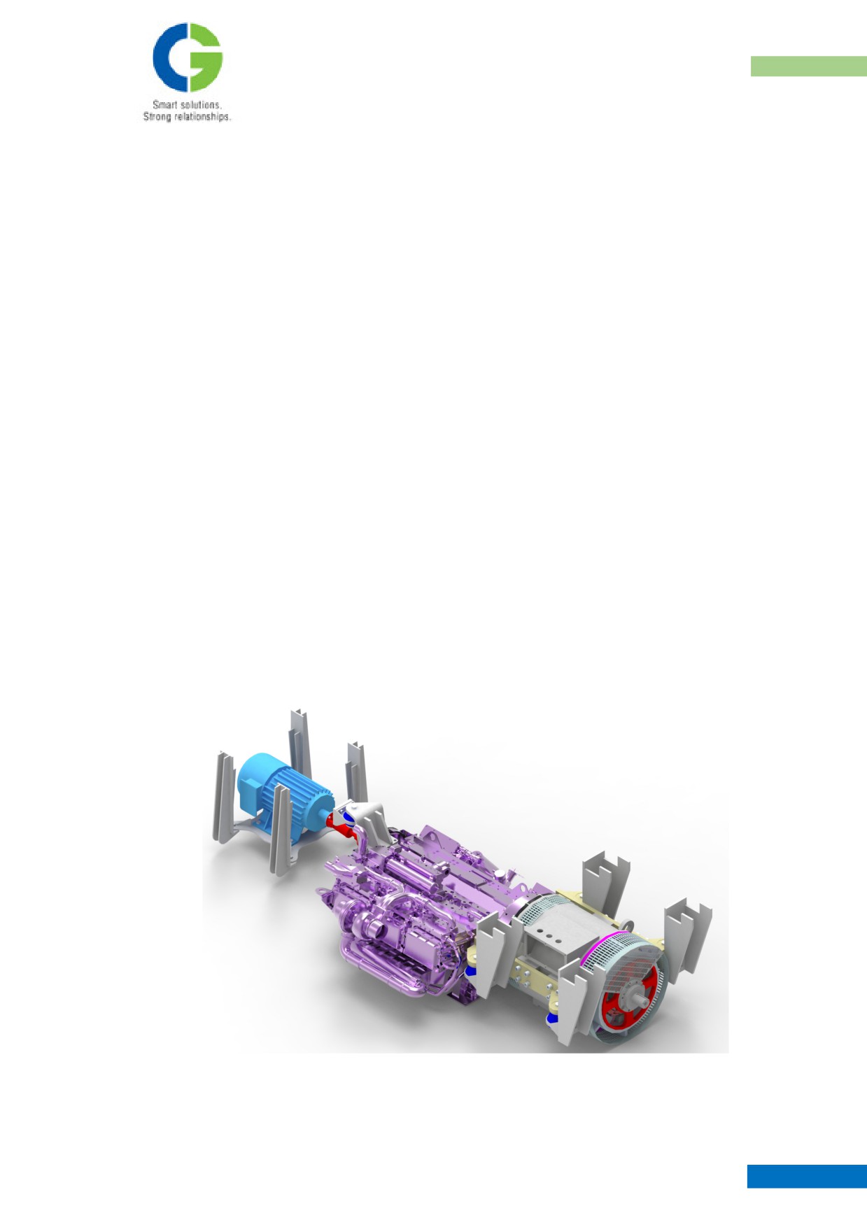
POWER PACK ARRANGEMENT
CHAPTER II
POWER PACK ARRANGEMENT
1. Introduction
The Diesel Electric Tower Car (DETC) is equipped with two set of under slung mounted Power packs.
Each Power pack consists of one under slung Engine (NTA-855 R), one Traction Alternator - 230 kW
(C1009A1) & one auxiliary alternator connected by a cardan shaft and flexible coupling. The car consists
of two bogies (4 axles), each axle is powered by the traction motor. The engine flywheel is directly
coupled with Traction alternator with the help of flex plates. These flex plate couplings are used to
compensate Axial, Angular and radial displacement of connected machines. Flex plates are provided to
absorb shocks on torque, by which it will minimize vibration, and transmits the power. The output power
of alternator is rectified to DC & fed to the traction motors.
These two Power pack units are synchronized & regulated to provide total traction power as a single
system when controlled from either cabin. Two cabins one on each end is provided for the purpose.
Provision also exists to isolate any of the power packs and run the vehicle. Driver’s desk mainly consists
of controls for Engine, Alternator and Pneumatic Brakes, Indication lamps, Gauges, switches, speed-
time-distance recorder etc., which will be functioning in conjunction with control cubicles. The complete
power pack is attached beneath the under frame.
MAINTENANCE MANUAL FOR DETC-US
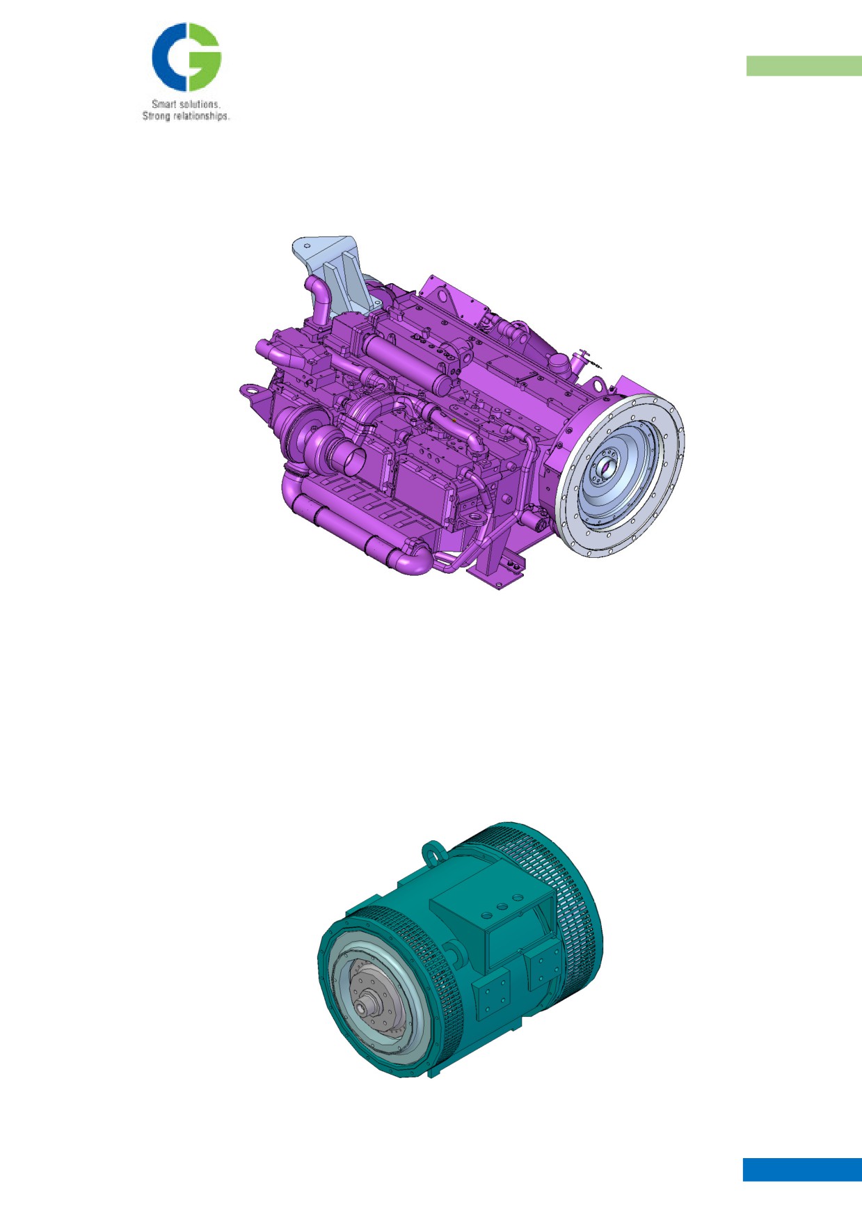
POWER PACK ARRANGEMENT
2. Major components of power pack
2.1 Engine
The model of the engine used in the equipment is NTA - 855R manufactured by M/s CIL, Pune. It is a
horizontal version engine suitable for under slung mounting. The specification of the engine is provided
in the specification section. This engine is supported at three points, viz, one support at front end
(vibration damper side) and two supports at rear end (Flywheel side). All the three supports are bracket
mounted with Anti vibration units.
2.2 Traction Alternator
MAINTENANCE MANUAL FOR DETC-US
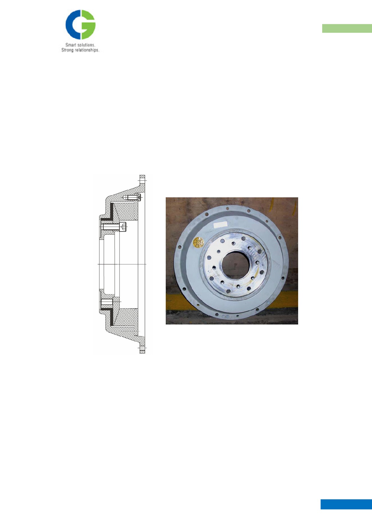
POWER PACK ARRANGEMENT
The alternator used in the car is C1009A1, manufactured by M/s CG, Bhopal. This alternator caters to
supply electrical power for main Traction. It is under slung mounted with suitable brackets and is driven
from engine directly through the flex plates. The specification of the alternator is provided in the
specification section. This alternator is supported on four points. All the four supports are bracket
mounted, consisting of two Main Brackets which positively holds both the coupled engine and alternator
together. These brackets rest on four Anti vibration units. The AVM’s are pre-compressed in the
assembly position. The mounting fasteners for these AVM are torque tightened and locked with split pin.
2.3 Flexible Coupling
In this power pack, the flexible coupling is used to connect the engine to auxiliary alternator through a
XLO cardan shaft. This coupling is manufactured by M/s.Vulkan. This coupling is selected to suit
maximum torque & speed of Auxiliary Alternator. These highly flexible couplings are guided radially &
axially. All the transmitting parts are arranged without clearance so that no wear will occur during the
rotation. The rubber element is suitable for temperature between
-40°C & +90°C & is internally
vulcanized to the ring. The permissible angular coupling displacement is 0.5°.
2.4 Auxiliary Alternator
Two 8 KW, 110V DC. Brush less, foot mounted Auxiliary Alternator is provided in the DETC, one each
for power pack. These alternators caters to supply electrical power for Battery charging & Control source
MAINTENANCE MANUAL FOR DETC-US
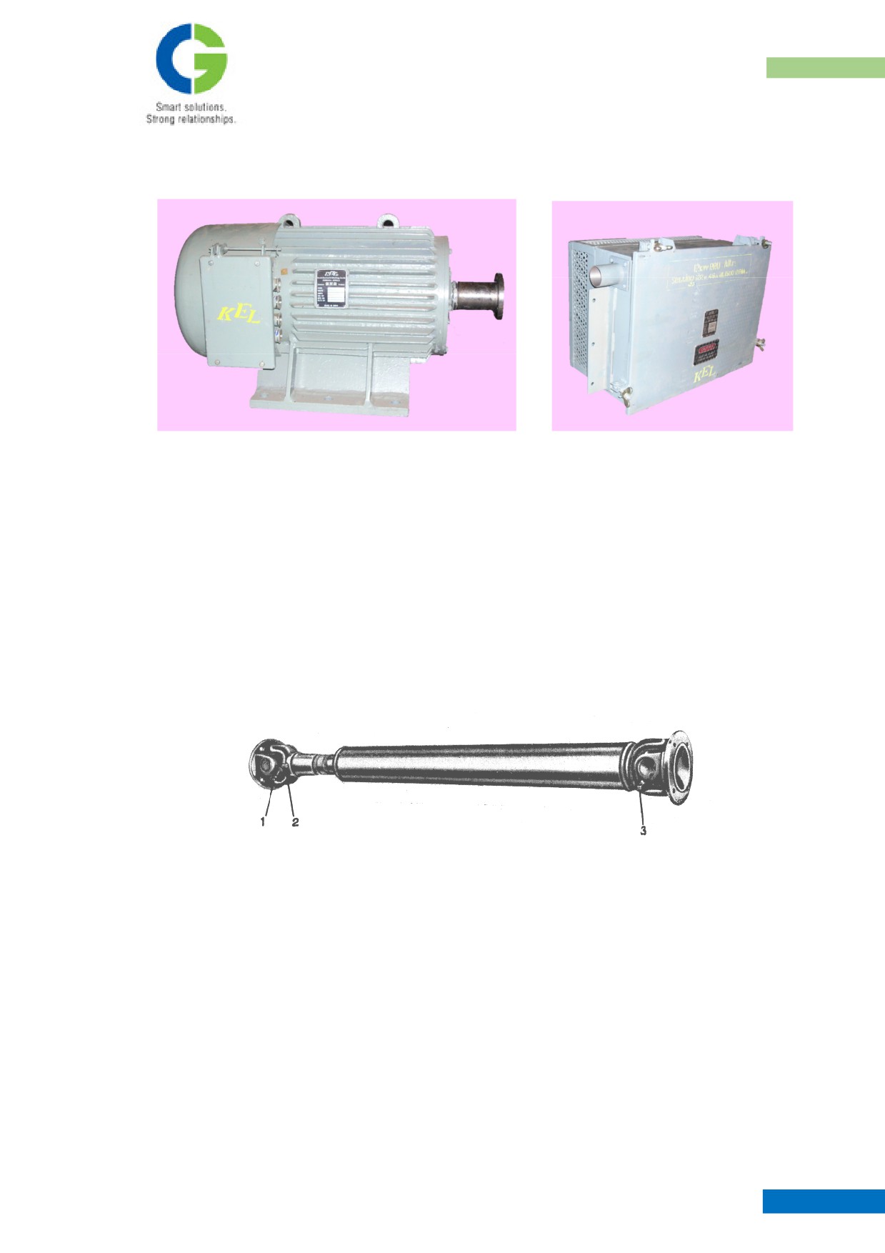
POWER PACK ARRANGEMENT
Supply, coach lights, fans, cab & head lights, tail lights, flasher lights etc. It is under slung mounted with
suitable brackets and is driven from engine vibration damper through a cardan shaft.
A static regulator cum rectifier unit rectifies the three-phase AC alternator output. A constant voltage of
122 Volts DC (65% regulates DC output at a maximum load current of 65 Amps @ idle engine speed of
700 rpm) is utilized.
2.5 Cardan Shaft
Cardan shaft is used to connect the flexible coupling mounted over the diesel engine to the coupling
flange mounted over the auxiliary alternator.
Maintenance and service related procedure for cardan shaft is explained in detail in Annexure 1 of this
document.
MAINTENANCE MANUAL FOR DETC-US
POWER PACK ARRANGEMENT
3. Power Pack Mounting
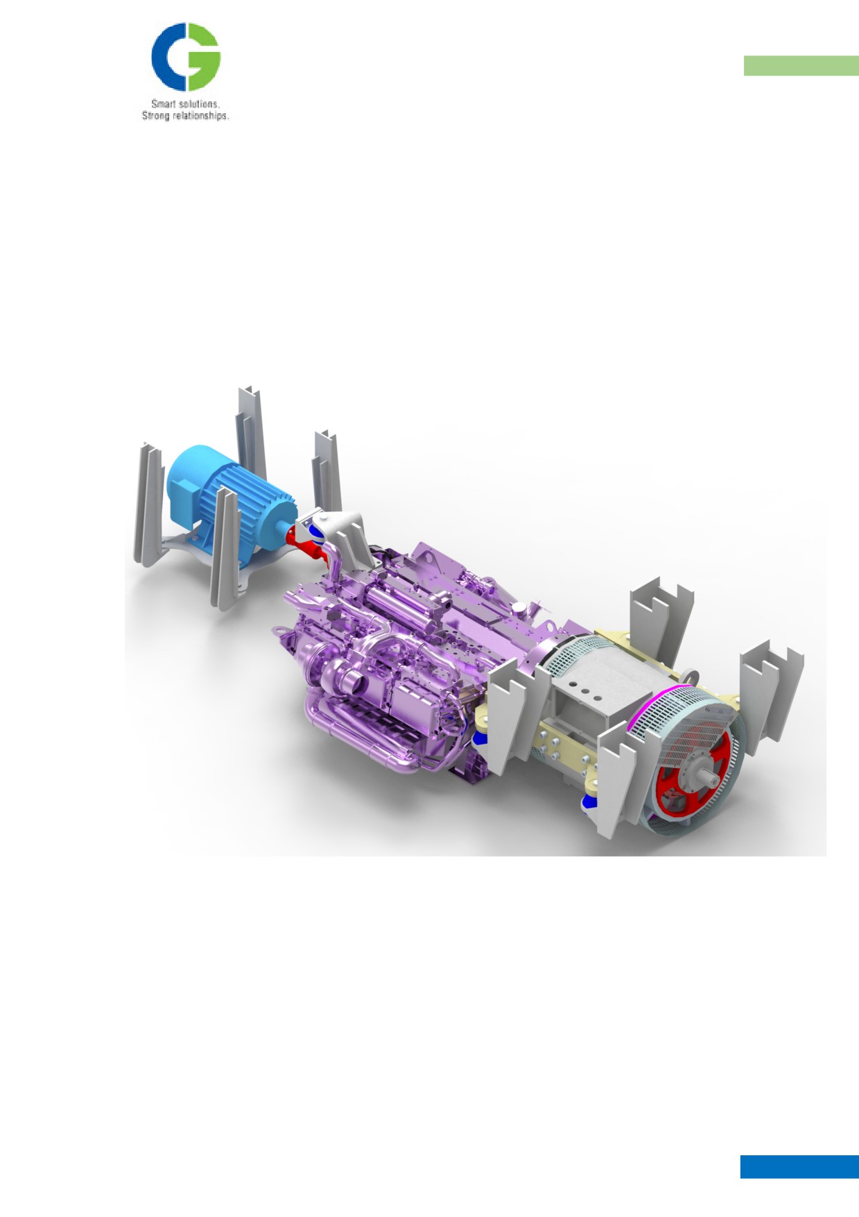
The Engine and Alternator (with the flex plates) are coupled together and positively held by two main
brackets at three points on either side of engine & alternator. Along with this, the auxiliary alternator end
of the Engine is held by a ‘Z’ Bracket. This whole power pack assembly has five suspending points,
which rests over anti vibration mountings, held rigidly by vertical brackets welded to under frame
structural members. This arrangement has low vibration transmissibility to the under frame. For details of
mounting, refer power pack drawing.
MAINTENANCE MANUAL FOR DETC-US
POWER PACK ARRANGEMENT
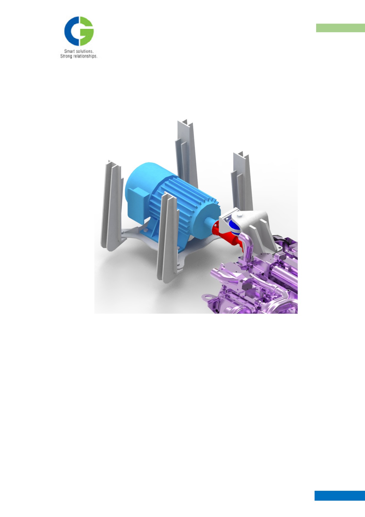
The auxiliary alternator is then mounted over a bracket held by four vertical brackets, which are
fabricated from the under frame structure. The Aux. alternator is driven by an XLO cardan shaft through
a flexible coupling. For more details refer power pack arrangement drawing.
MAINTENANCE MANUAL FOR DETC-US
4. AIR INTAKE ARRANGEMENT
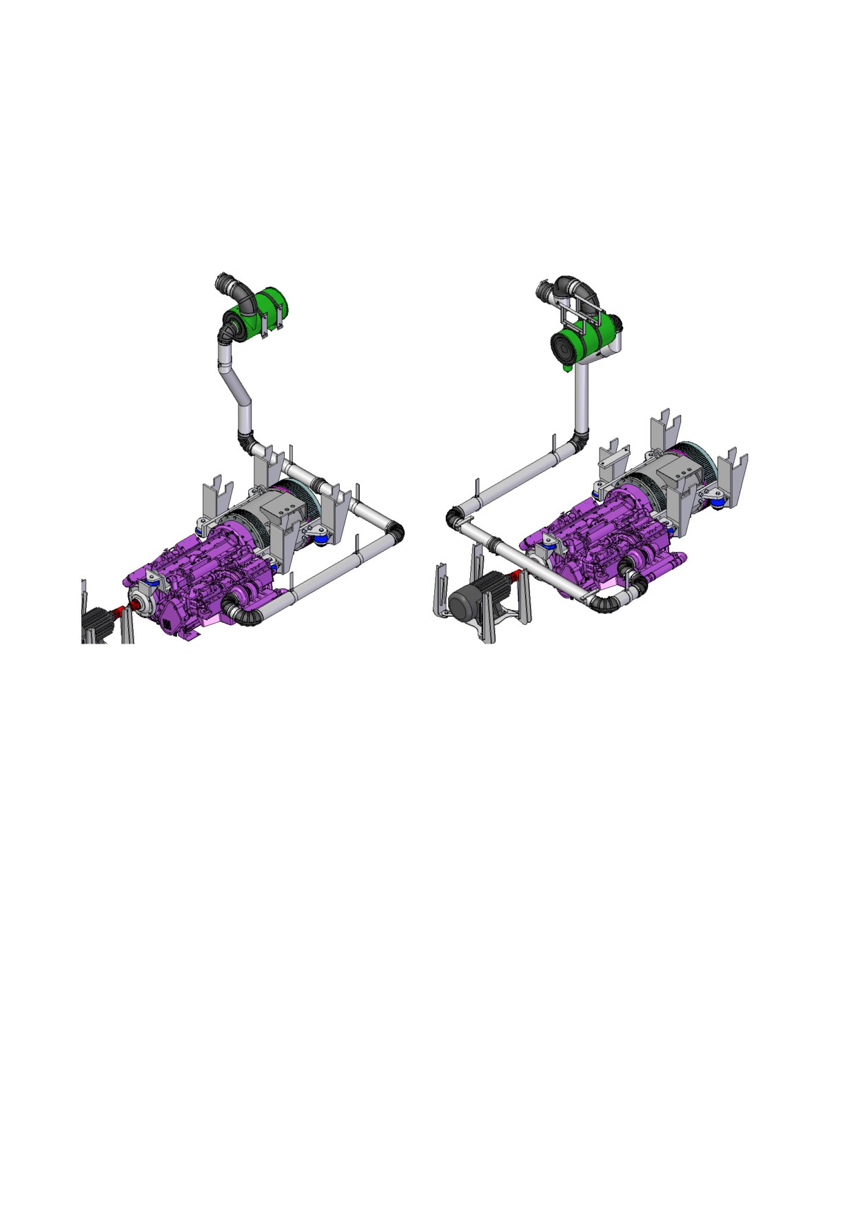
Air cleaners are positioned inside the coach as shown in the Drawing No. 45831110. Air cleaner sucks the
fresh air from atmosphere through a conical arrangement mounted on coach side wall, outlet pipe is routed
below the floor to the engine air inlet point. Suitable clamping is done to support the pipes at required places.
Below picture shows the air intake routing for either side of the power packs.
POWER PACK ARRANGEMENT
5. EXHAUST SILENCER ARRANGEMENT
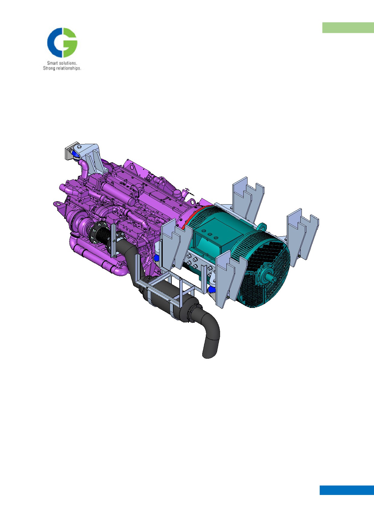
Exhaust silencer is mounted under slung and exhaust smoke will be let to atmosphere through the muffler
from the engine outlet. Thermal Insulation for the pipes provided with cladding the appropriate material from
Q-shield to avoid exposure to hazardous hot surfaces at the time of maintenance.
MAINTENANCE MANUAL FOR DETC-US
POWER PACK ARRANGEMENT
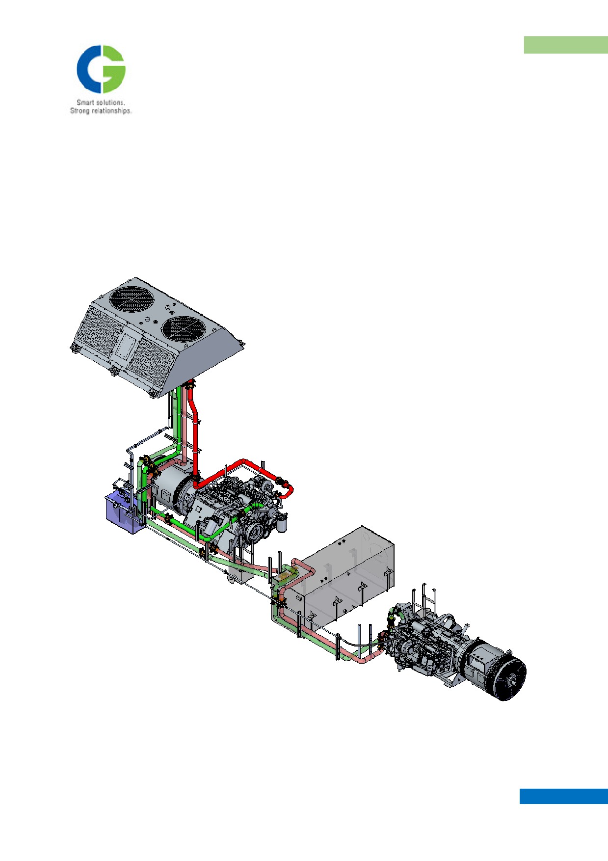
6. RADIATOR MOUNTING & PIPING ARRANGEMENT
Radiator unit is mounted on roof of the coach. A single radiator unit is provided for both the engines. This
radiator unit is mounted on AVM to damp vibrations. The sucker type fan is used in the system; it sucks the
air through the radiator core and blows to the atmosphere to cool the water circulating inside core. The fans
are driven by hydro static motors.
Pipe routings from both the engine passes beneath the under frame at intricate conditions, passing through
the
floor
(suitable
cutouts
are
provided)
and
connects
the
radiator.
MAINTENANCE MANUAL FOR DETC-US
POWER PACK ARRANGEMENT
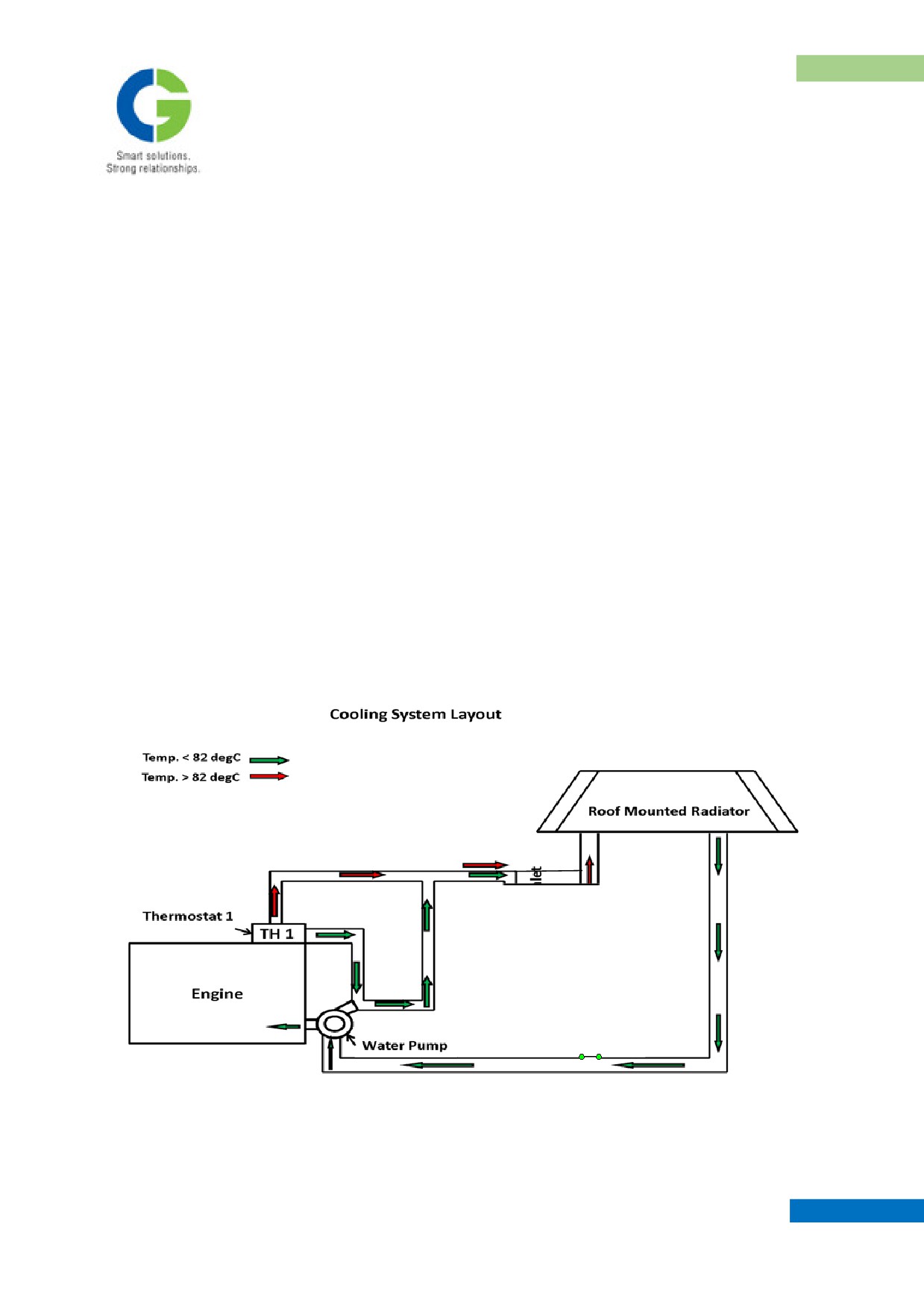
The radiator unit has following pipe connections:
1.
Inlet
2.
Outlet
3.
Vent
4.
Over flow
5.
By pass line
The hot water that is pumped out from the engine is connected to inlet port of radiator. The hot water enters
from the top most point of the core. Hot water flows through the core, gets cooled and comes out through
outlet pipe at bottom most point of the core. This outlet pipe from radiator unit is connected to water inlet
port of Engine and cools the engine, water jackets after cooler, compressor and exhaust manifold while
circulating inside the engine. Water is pumped to the Thermostat housing on the engine; this senses the water
temperature in the system and controls the water flow to the radiator.
MAINTENANCE MANUAL FOR DETC-US
POWER PACK ARRANGEMENT
7. HYDRAULIC TANK AND HYDRAULIC CIRCUIT
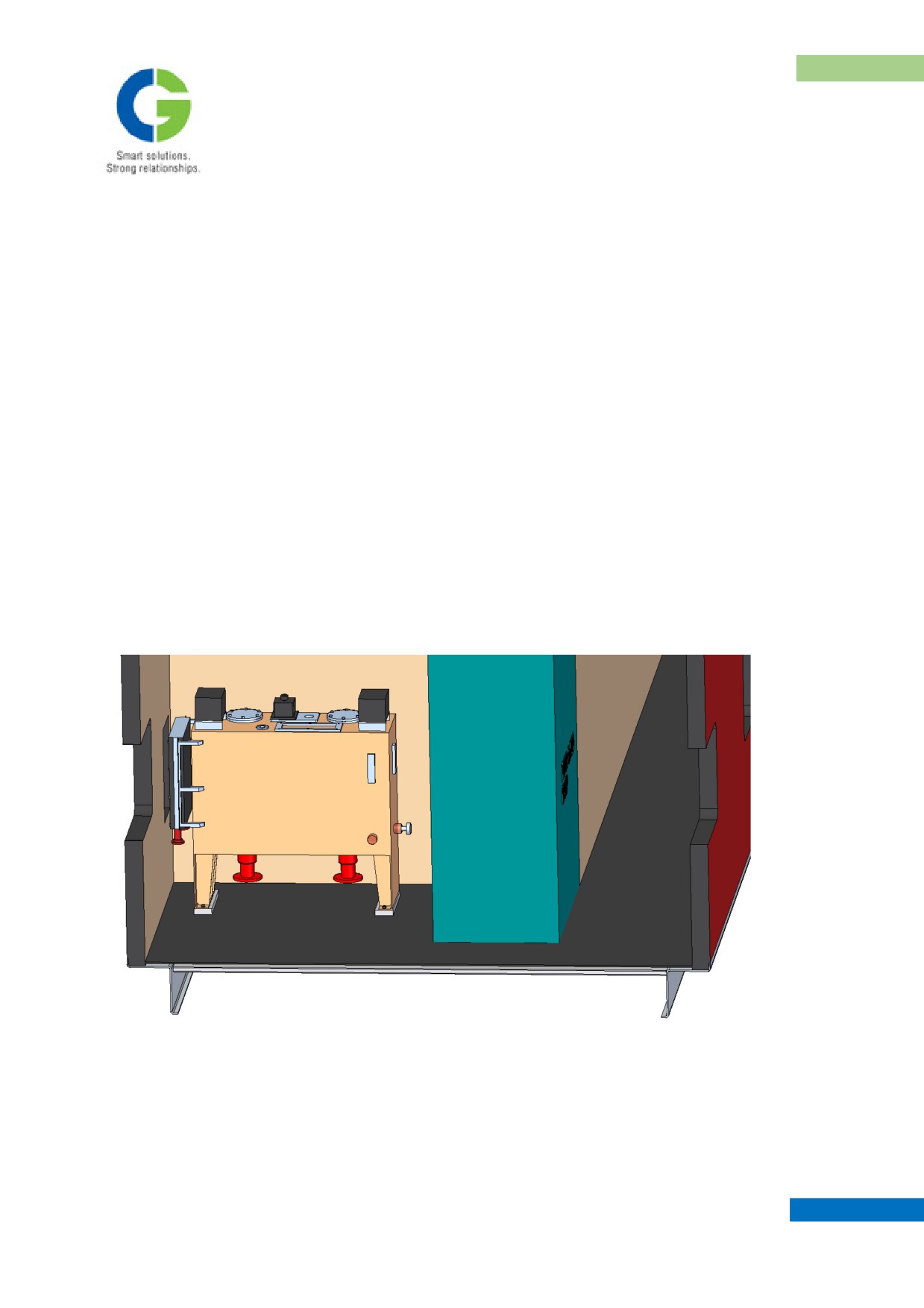
A single common hydraulic tank is provided for both engine’s Cooling system, it is located inside the coach.
This tank is equipped with filling cap, sight glass, manifold blocks, oil cooler, return filter ect., on it.
The system has radiator fans driven at variable speeds depending upon the radiator water temperature. It is a
Hydrostatic system in which two fans are driven by independent hydraulic motors from variable flow
delivered by a respective engine driven hydraulic pump. Independent Thermatic valves are mounted on the
water manifold block at the each engine water outlet, where the hot water exits for onward routing to the
radiator.
The Thermatic valve senses the temperature and regulates pressure on the pump's flow control port. This
action affects the hydraulic pump's output flow rate according to the water temperature. It increases with
increase in water temperature. The variable flow connected to motor regulates the variable speed of motor
according to the water temperature. Thus, the entire hydrostatic fan drive system forms a closed loop control
system.
MAINTENANCE MANUAL FOR DETC-US
POWER PACK ARRANGEMENT
7.1 Hydraulic pump
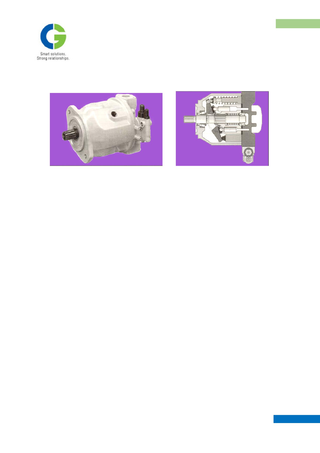
A variable displacement pump is mounted on the engine and it is directly driven by engine gear drive
from gear case cover. This hydraulic pump has swash-plate design.
Flow of hydraulic oil is proportional to drive speed required. Fluid Displacement is infinitely
variable by adjustment of swash-plate angle. By adjusting the position of swash-plate, it is possible
to smoothly vary the flow. It has a pilot control valve, which controls the position of swash-plate,
which in turn regulates delivery of fluid flow of the pump after receiving feedback from remote
position. Thermatic valve forms the remote sensing & feedback element for the control.
7.1.1 Working of Variable displacement pump:
1. Hydraulic pump has multiple cylinders whose movements are obtained from rotation of drive shaft.
2. Cylinders suck & deliver liquid by their reciprocating motion proportional to stroke length
(displacement) of the cylinders.
3. These strokes are directly controlled by inclination of the swash plate whose position is governed by
Pilot control valve
4. Pilot control valve receives feed back from remote control (Thermatic valve).
5. Remote control valve is also called as Thermal Relief / Thermatic control valve (as its feedback is
translated on the basis of rise in engine coolant temperature).
6. Hydraulic pump has a leakage return line back to hydraulic tank.
MAINTENANCE MANUAL FOR DETC-US
POWER PACK ARRANGEMENT
7.2 Hydraulic motor
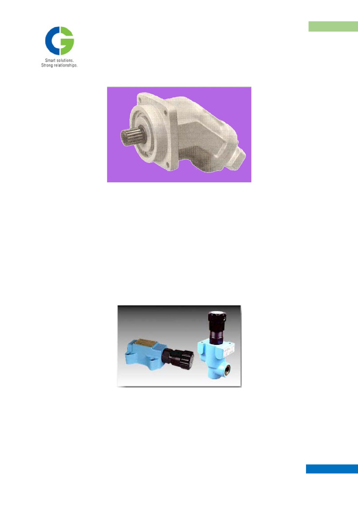
The Hydraulic motor is used in this system is of bent axis design with fixed displacement of
cylinders. The pressurized oil, which is pumped from hydraulic pump, routed as inlet to the motor &
develops the torque and speed of motor. Hydraulic motor rotational speed is directly proportional to
flow of the pump; and pressure of the liquid is directly proportional to the torque developed by the
shaft. Hydraulic motor also has a return line flowing freely back to tank. Supply & return lines to the
motor are routed through a manifold block.
7.3 Pressure relief valve
Pressure relief valve is always connected in main delivery line of hydraulic pump (pressure line) to
limit the system pressure to set value.
MAINTENANCE MANUAL FOR DETC-US
POWER PACK ARRANGEMENT
7.3.1 Operation of Pressure Relief Valve:
1. System pressure acts on the main spool.
2. At the same time pressure acts via a pilot line fitted with jets, on pilot poppet.
3. If the system pressure exceeds the value set with the spring, the pilot poppet opens and pilot oil is
allowed to flow back to the tank.
4. The jet combination causes sufficient pressure drop across the main spool.
5. The main spool is lifted from its seat and opens the pressure line connection to tank while operating
pressure is maintained, as desired.
6. The spring tension on poppet valve can be adjusted by setting knob to any desired pressure, from 0-
250 bar (set pressure around 160 to 180 bar).
7. The pilot control port should be connected to receive flow for pilot poppet valve.
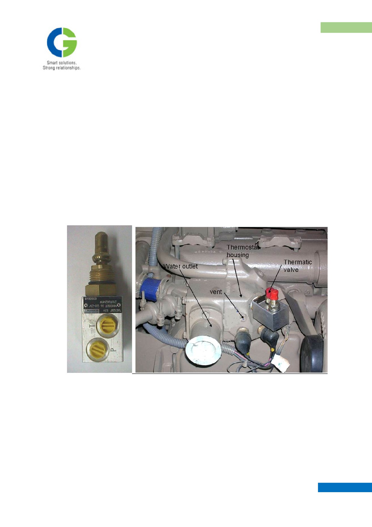
7.4 Thermal Relief / Thermatic Valve:
Thermatic valve is a direct operated relief valve of poppet-seat design, where the nominal pressure is
proportional to the temperature sensing with in set limits. It is mounted on engine's water outlet
connection. It senses the temperature of engine water outlet and functions.
MAINTENANCE MANUAL FOR DETC-US
POWER PACK ARRANGEMENT
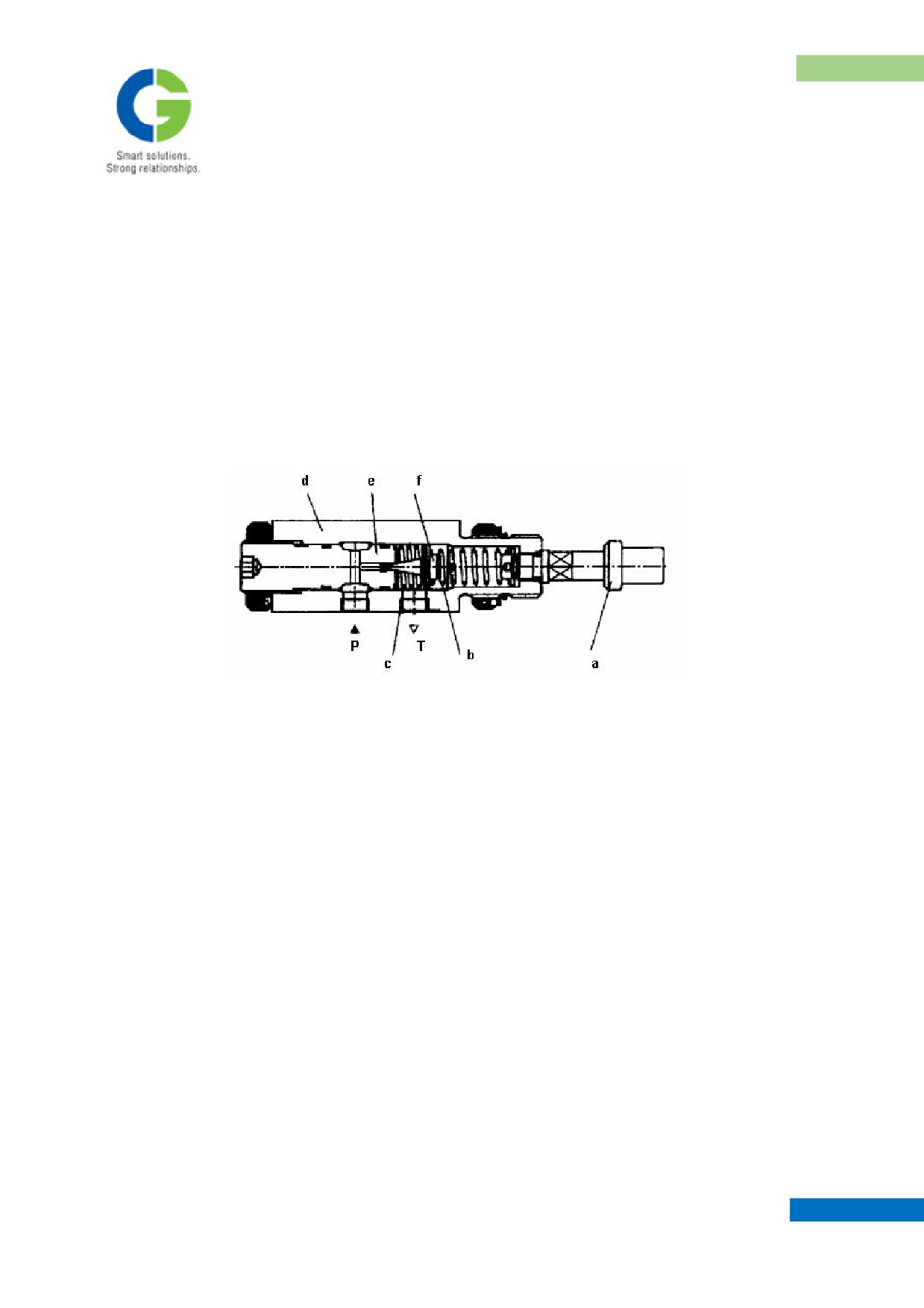
Main elements of Thermatic valve are:
1. Thermal Element
2. Control Spring
3. Reset Spring
4. Valve Housing
5. Valve Seat
6. Poppet
P. Pressure port
T. Tank return port
7.4.1 Operation of Thermatic Valve:
1. When Engine outlet water temperature is below 82°C, hydraulic oil from hydraulic pump pilot valve
freely passes through the pressure port 'P' of valve assembly to tank through Tank return port 'T'.
2. When temperature rises above 82°C, thermal element 'a' expands and starts moving its plunger
against control spring 'b'.
3. This moves poppet ' f ' towards valve seat 'e' and creates restriction to incoming flow and generates
backpressure.
4. This backpressure is treated as feedback by pilot control valve, which now starts controlling
inclination of swash plate for more delivery coming out of hydraulic pump.
5. When the temperature drops below 82°C at the thermal element 'a', control spring 'b' is released and
reset spring 'c' allows pressurized hydraulic oil to drain to tank.
MAINTENANCE MANUAL FOR DETC-US
POWER PACK ARRANGEMENT
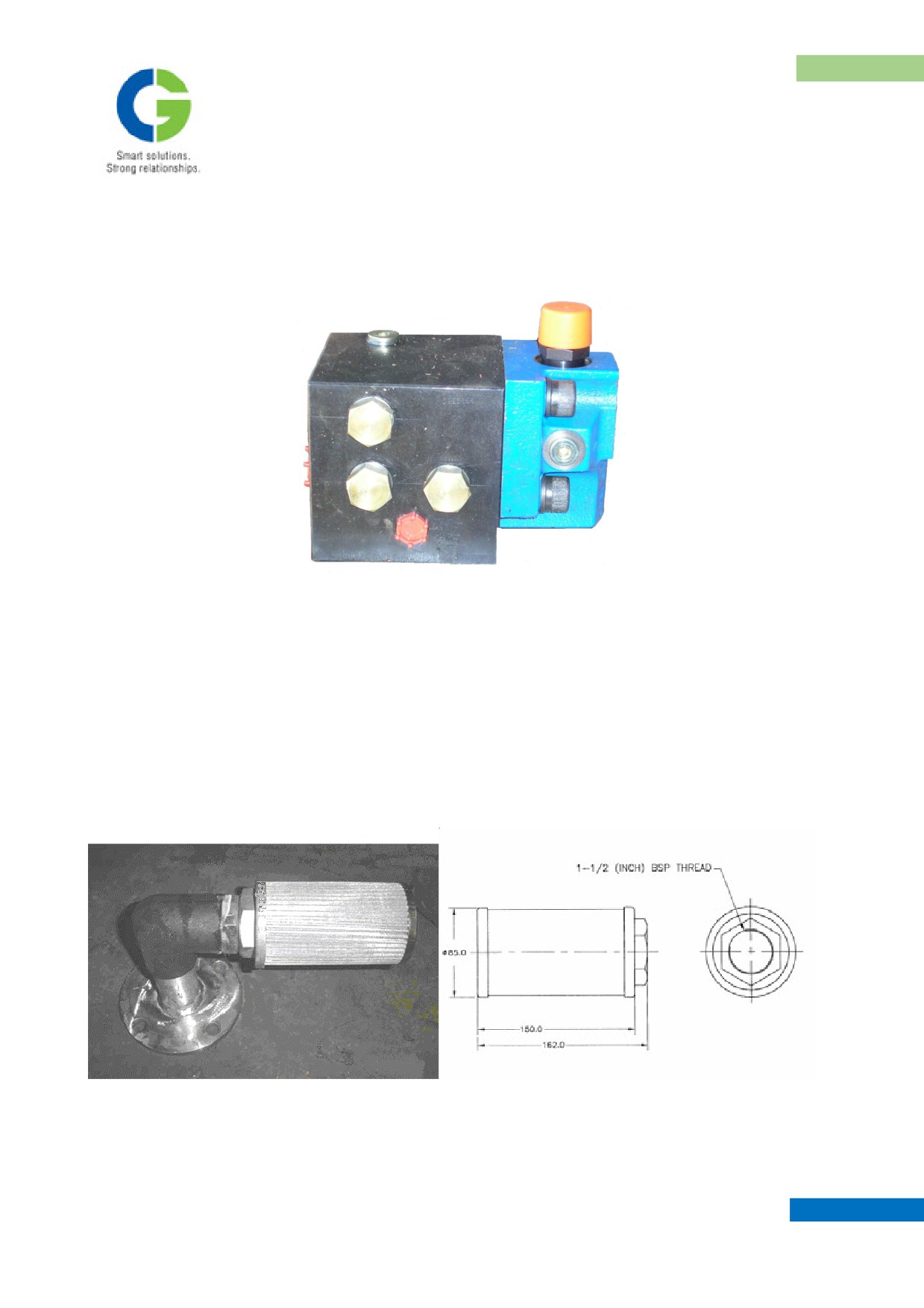
7.5 Manifold block
Manifold block is used primarily for two purposes
1. Simplify hydraulic circuit.
2. Reduce number of components in the system.
Manifold block is a solid block of steel which houses a several non-return valves (check valves),
Pressure relief valves connected to achieve function by internal passages of the block. It facilitates
hose connections to various points in the system.
All of them contain cartridge type check valves. Care to be taken for cleanliness of oil because a
small dirt or foreign material entrapped in their seating area renders these valves non-functioning.
7.6 Suction Strainer
MAINTENANCE MANUAL FOR DETC-US
POWER PACK ARRANGEMENT
1. Separate Strainers are fitted inside the hydraulic tank one each in the suction line and vent line of
pump.
2. Precautions be taken to avoid ingress of dirt particles in the hydraulic tank during initial filling or
scheduled maintenance of the hydraulic system.
3. Suction strainer can remove particles up to 150 microns.
4. The strainer protects pump from the entry of harmful solid particles.
7.7 Return line filter
1. Return Line filter is mounted directly on hydraulic tank.
2. It cleans hydraulic oil that may get contaminated due to poor handling or undesirable entry of dust in
the system or wear and tear of system components.
3. Return Line filter can filter particles up to 10 microns.
4. There is a container around the filter for the purpose of trapping dirt. When element is removed, this
container is drawn out with it, so that any residual dirt is not allowed to flow back into the tank.
5. These filters are fitted with restriction indicator on the top of its head which pops up showing red
signal whenever pressure drop across filter element is above 2.5 bar.
MAINTENANCE MANUAL FOR DETC-US
POWER PACK ARRANGEMENT
8.0
FUEL LINE PIPING ARRANGEMENT
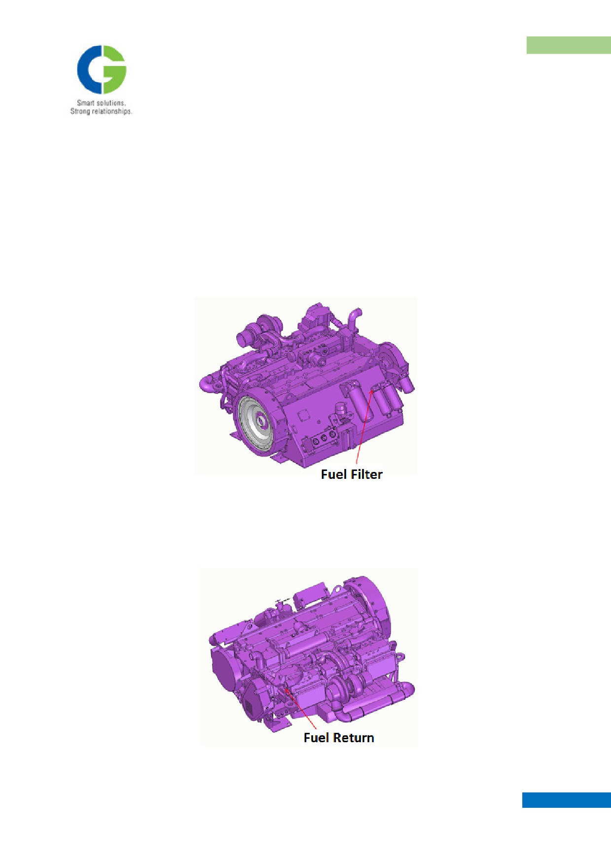
A common under slung fuel tank is provided to cater both the power pack of main traction. Each power pack
draws fuel from the fuel tank through an independent piping system. Each line consists of a shut off valve to
isolate the supply whenever required for any maintenance. Suspended particles in the fuel settles at the
bottom of the tank due to gravity. From shut off valve further piping is done via a strainer, water separator,
fuel filter and finally to fuel actuator on the engine. These connections are equipped with flexible hoses. Fuel
filter will filter any foreign particles, waste etc. & thus obtained clean fuel is routed by a hose to Fuel pump
mounted on the engine.
Excess fuel expelled by the engine is returned back to the fuel tank connected by a hose and metal pipes
direct to the common under slung fuel tank. (Fuel return point is positioned at bottom of engine).
MAINTENANCE MANUAL FOR DETC-US
POWER PACK ARRANGEMENT
9.
WATER RISING APPARATUS
Engine block, radiator unit and connecting piping system needs to be filled with coolant prior to starting the
power pack and also may require periodical topping up. The Radiator unit is mounted over the coach roof.
Climbing over the roof for periodical topping up of the radiator with coolant is a laborious, time consuming
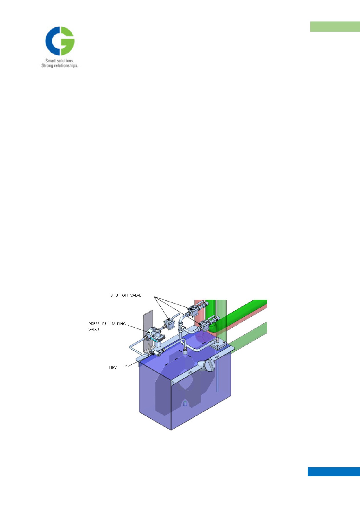
and also poses high voltage power line hazard. A pneumatically operated water rising apparatus (WRA) is
mounted under slung to ease out the filling / topping up of coolant. A stainless steel tank comprising a
coolant capacity of 100 liters provided.
A pneumatic line with a limiting valve set at 0.5 to 0.8 kg/cm², a non return valve & insolating valve is
provided before connecting to tank. When the radiator cooling system required to topping up, the existing
pneumatic system’s pressured air is allowed inside the tank and in turn this will pressurizes the water to get
out of the tank, feeding the cold water line of the radiator through an independent isolating cock and thus
tops up the radiator. There are two independent isolating valves are provided in the water lines, these are
required to select or open depends on the required engine cooling system to be topped up. The check valve
provided in the pneumatic line prevents the reverse entry of coolant water into the pneumatic line. During
each top up the shut off valve provided in pneumatic line to be opened first & further isolating valve
provided in water like to be opened depends on the required engine to be topped up. After completing the
process both isolating valves to be closed compulsorily.
MAINTENANCE MANUAL FOR DETC-US
POWER PACK ARRANGEMENT
10. PANEL RESISTOR BOX MOUNTING ARRANGEMENT
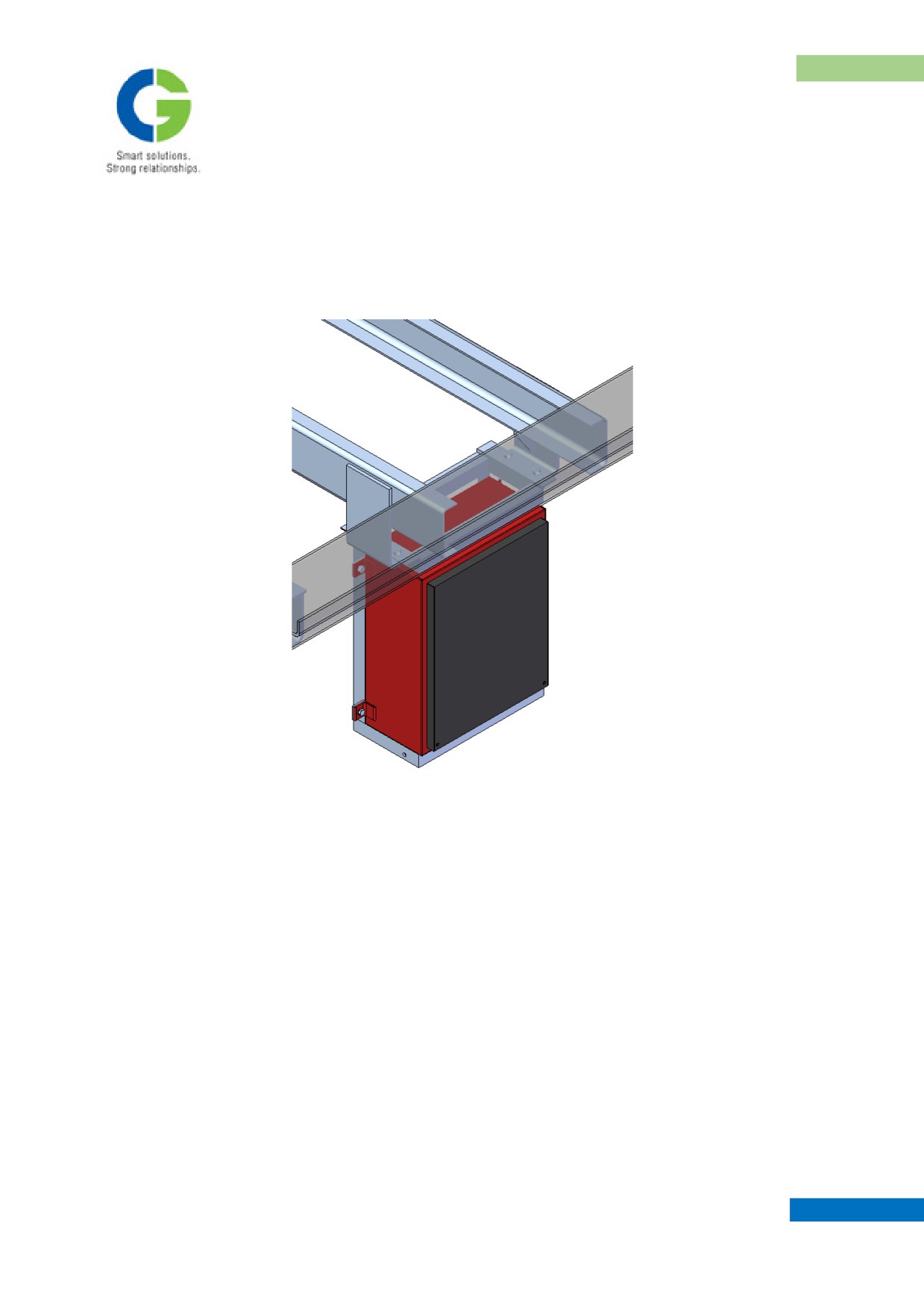
One number of panel resister box houses 6 resistors in a box. This box mounted under slung, supports are
taken from the under frame structure as shown in the figure.
The box housed excitation resistor panels for both the alternators. One set of panel consists of 3 resistors
each of 36 Ohms, 300 W. Theses 3 resistors are connected in parallel making the equivalent resistance of the
circuit 12 ohms.
MAINTENANCE MANUAL FOR DETC-US
POWER PACK ARRANGEMENT
11. AFTER COOLER MOUNTING ARRANGEMENT
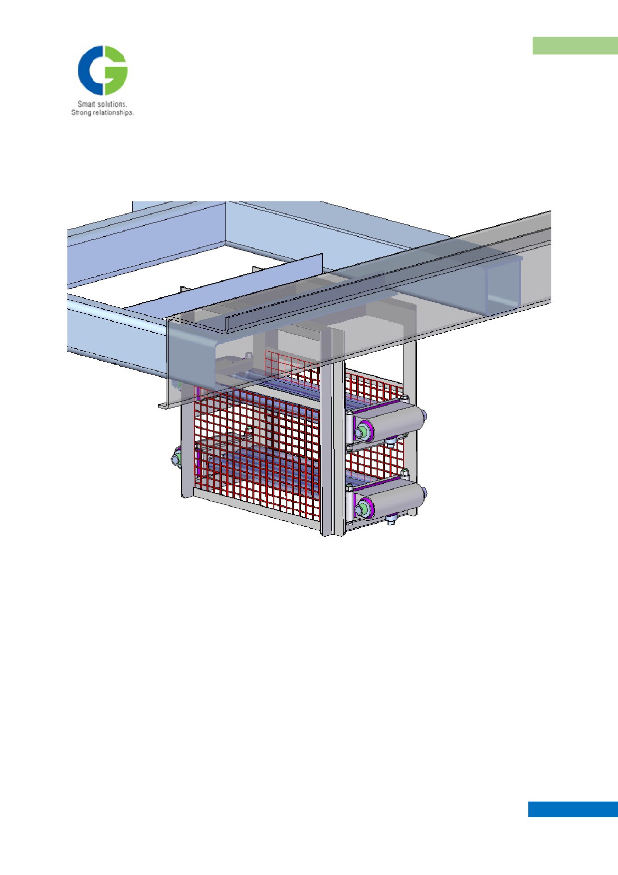
Two numbers of after coolers, Universal make are mounted under slung, supports are taken from the under
frame structure as shown in the figure. These after cooler is connected in output of air compressor outlet.
MAINTENANCE MANUAL FOR DETC-US
POWER PACK ARRANGEMENT
12. MAINTENANCE SCHEDULE FOR DETC POWERPACK
Diesel
Sl.
Engine
Parts
Period
Maintenance Step
Remarks
No.
running /
stopped
1.
General
Daily
Stopped
• Check visually all equipment for
Correct if
any
Examination
visible defects, loose bolt & nuts,
defects
leakages, missing parts etc.
Waste jute should
• Check lube oils, fuel, cooling
never be used.
water and air system for leakage
and rectify if necessary.
• Clean all equipment with lintel
cloth.
• Clean the vehicle thoroughly with
a jet of water and scrub down all
dirt and wash again.
2.
Diesel
Daily
Stopped
Refer Diesel engine part.
Engine
3
Cardan Shaft
Daily
Stopped
Check Cardan Shaft for any visual
damage.
4.
Alternators
Daily
Running
Check for any abnormal noise or over
heating.
5.
Diesel
Daily
Running
Refer Diesel engine part.
Engine
6.
Gauges
&
Daily
Running
Check the Gauge & instrument
instrument
operations
7.
Aux.
Daily
Running
Check if alternator is charging the
Alternator
battery.
MAINTENANCE MANUAL FOR DETC-US
POWER PACK ARRANGEMENT
NOTES
-----------------------------------------------------------------------------------------------------------------------------------
-----------------------------------------------------------------------------------------------------------------------------------
-----------------------------------------------------------------------------------------------------------------------------------
-----------------------------------------------------------------------------------------------------------------------------------
-----------------------------------------------------------------------------------------------------------------------------------
-----------------------------------------------------------------------------------------------------------------------------------
-----------------------------------------------------------------------------------------------------------------------------------
-----------------------------------------------------------------------------------------------------------------------------------
-----------------------------------------------------------------------------------------------------------------------------------
-----------------------------------------------------------------------------------------------------------------------------------
-----------------------------------------------------------------------------------------------------------------------------------
-----------------------------------------------------------------------------------------------------------------------------------
-----------------------------------------------------------------------------------------------------------------------------------
-----------------------------------------------------------------------------------------------------------------------------------
-----------------------------------------------------------------------------------------------------------------------------------
-----------------------------------------------------------------------------------------------------------------------------------
MAINTENANCE MANUAL FOR DETC-US
CHAPTER III
CIRCUIT DESCRIPTION
1. POWER CIRCUITRY
2. AUXILIARY CIRCUITRY
3. CONTROL CIRCUITRY
Maintenance Manual
DIESEL ELECTRIC TOWER CAR | UNDER SLUNG TRANSMISSION
CIRCUIT DESCRIPTION
CHAPTER III
CIRCUIT DESCRIPTION
1. POWER CIRCUITRY
1.1 SYSTEM DESCRIPTION
A self propelled Diesel Electric Tower Car (DETC) is used for periodical inspection, patrolling and
maintenance of traction overhead equipment. It is also used for attending sites of breakdown, restoration of
damaged OHE equipment. This can also be used to erect small lengths of catenary and contact wire by way
of repairs of damaged OHE.
The power equipment of Diesel Electric Tower Car comprises of two power packs, two separate alternators
two power rectifiers & four traction motors to meet all operating conditions of Diesel Electric Tower Car.
The power pack consists of a Diesel Engine of Cummins India make type NTA-855R developing a power of
340 HP @ 1800 RPM continuously and a Brushless CGL make traction alternator type C1009A1, matching
rectifier, exciter and rotating diode set capable of developing around 310 HP input to traction (by each power
pack).
The Traction Alternator is a single bearing type and compatible for coupling with Cummins Diesel Engine
mentioned above. The exciter field current is limited to 6 amps during entire working range of DETC.
The main rectifiers are suitable for over board mounting and are used for rectifying the output of traction
alternators. The power rectifier assembly is suitable for operation under one bridge failure condition. It has
built-in blower arrangement with fan failure protection.
The traction motors (Type TM2141C) are suitable for mounting on DEMU bogie of Indian Railways. The
Traction Motor is self-cooled type and complies with requirements of IEC - 60349-1. The traction motor has
moulded inter-pole & main-pole coils bonded with poles. The four traction motors in 4P combination will
operate in full field only, utilising full capability of traction alternator. Avoidance of going into a weak field
is beneficial from operation point of view, especially utilisation of available adhesion. In addition, such a
combination provides following advantages:
MAINTENANCE MANUAL FOR DETC-US
CIRCUIT DESCRIPTION
-
Reduction in control equipment
-
Reduction in maintenance cost
-
Avoiding transition jerks and loss of power normally encountered in transition
An electronic diesel engine speed governing, alternator exciter excitation and load control module, type
LCC107B of GAC make, control the diesel engine speed & excitation of the Traction Alternator. The
experience shows that adoption of such a system enables utilisation of maximum diesel engine power on rail,
thus optimally utilising the installed power.
The diesel engine speed will be regulated through the 8 pre-selected steps (notches). Driver can operate the
DETC at any notch depending upon speed restrictions / desired.
2. AUXILIARY CIRCUITRY
Two 8 kW Auxiliary Brushless Alternator rectifier and regulator system, supply 122±5% Volts DC for
Auxiliaries. The alternator is self-cooled and is directly driven from Diesel Engine shaft extension through
cardon shaft and flexible coupling. The output of the rectifier regulator is 125V ± 5%. The regulated
voltage is available from no load to full load and idle engine RPM to maximum engine RPM.
A 110V DC lead acid battery (Not in CGL Scope of Supply) will float against the auxiliary power and will
thus remain in charged condition during normal operation. This battery can supply to fans, lighting and
control loads.
PERFORMANCE OF THE SYSTEM
Performance obtainable using two 340 HP diesel engines at 8th notch & 914 mm half worn wheels and 20/91
gear ratio, two traction motors fed from a power pack in Permanent Parallel combination (operating in full
field only) is shown on curve No. 50702001.
A maximum speed of 110 Km/h is obtainable with the power equipment proposed by us and meets the
following performance requirements as specified in ICF specification no ICF/M/D/SPEC - 300. In addition,
use of our equipment gives following performance capability.
1.
DETC can carry 12 tons of payload without any additional equipment.
MAINTENANCE MANUAL FOR DETC-US
CIRCUIT DESCRIPTION
2.
Period of continuous running for 4 hours at 100 kph on general tangent track followed by frequent to
& fro movement at walking speed for 1.5 hours.
3.
Period of continuous running at 40 kph on up or down gradient of 1 in 60 for 4 hours to be followed
by frequent to and fro movement at 5 kph for 1.5 hours on the same gradient.
4.
When running as a light vehicle, the DETC shall be capable of running at a speed of
a.
110 kph on level track.
b.
26 kph on a 1 in 33 up gradient
5.
The DETC will be able to start and haul a trailing load of 60 tons on up gradient of 1 in 60.
6.
When the DETC hauling a trailing load of 60 tons on 1 in 60 up gradient, the vehicle can reach a
maximum speed of 40 kph.
3. CONTROL CIRCUITRY
3.1 110 V DC SUPPLY
110 VDC supply is available in the coach from 110 VDC, 120 A-H battery. This supply is available to
control circuit in all positions of Battery Isolating Switch (BIS-110V). During OFF position, we can charge
the battery from external source through Battery charging socket. Two Nos. 8 kW Auxiliary Alternators
supply 120 ± 5% VDC to the system for control system operation, supply to electromagnetic equipment,
electropneumatic equipment, train lighting, Headlight, battery charging, Rectifier Blower Motors, Excitation
Control, Governor Supply etc. RCD1, RCD2 and RCD3 are not allowed battery to discharge and allow to
charge the battery when both the Auxiliary Alternators / either of the Auxiliary Alternators are in working
condition. Supply to both the Rectifier Blowers will be available from Auxiliary Alternators when both of
them are in working condition or even when one of the Auxiliary Alternators is working. During normal
working condition the 110 VDC Battery isolating switch shall be in “AA-1 & 2 IN CKT” position.
3.2 24 V DC SUPPLY
24 VDC Supply is available in the coach from 24 VDC battery. 20 A Diesel Engine mounted Battery
Charging Alternator (BCA) is used for charging the battery, supply to control circuit, electromagnetic
equipment, auxiliary equipment etc. This battery is isolated from the circuit when the battery is in OFF
position. When Diesel Engines are running, supply shall be available from BCA and corresponding charging
MAINTENANCE MANUAL FOR DETC-US
//////////////////////////////////////////