8 WHEELER DIESEL ELECRIC TOWER CAR WITH UNDERSLUNG TRANSMISSION. OPERATING & MAINTENANCE MANUAL (2019) - page 3
POWER RECTIFIER
5. MAINTENANCE
Although due to sufficiently rated quality components and material very low maintenance is required for the
unit, but following steps will help in giving trouble free service.
Atleast once a month open the side panels and clean the dust & soots collected on panels and within the unit with
dry compressed air or any other suitable means
Check all electrical connections and mechanical assemblies. If found loose, refit it.
Check air speed at outlet of each rectifier duct. It should be minimum 6 mts./ second at outlet.
Check healthiness of rectifier fuses. Failure of fuse will be indicated by ejected plunger of corresponding Trip
Indicator Fuse. If found blown, replace both main and trip indicator fuse after rectifying cause of fuse failure.
Clean the Insulators with cloth / brush.
Check conditions of resistors and capacitors. Replace if found damaged.
In case of failure of diode, please follow following removal & refitting procedure.
The fan is brushless type hence it does not need any specific maintenance.
Removal of Diode
Unscrew the lead of diode from busbar.
Remove the diode by removing the Allan bolts using suitable key.
Clean the diode with clean cloth. Check its healthiness. If found defective, use new one to replace it
Mounting of Diode
Clean the base of diode with clean cloth.
Apply a thin layer of silicon oil or good quality contact grease
Clean the surface area of heatsink on which diode is to be placed.
Using same/ same size Allan bolts refit the diode. Initially tighten bolts alternately half to one turn at a time so
that diode is clamped with equal force all over. Finally using torque wrench complete tightening of the bolts. The
specified torque limit is 1.7 to 2 KN.
Connect the end of lead on busbar.
MAINTENANCE MANUAL FOR DETC-US
POWER RECTIFIER
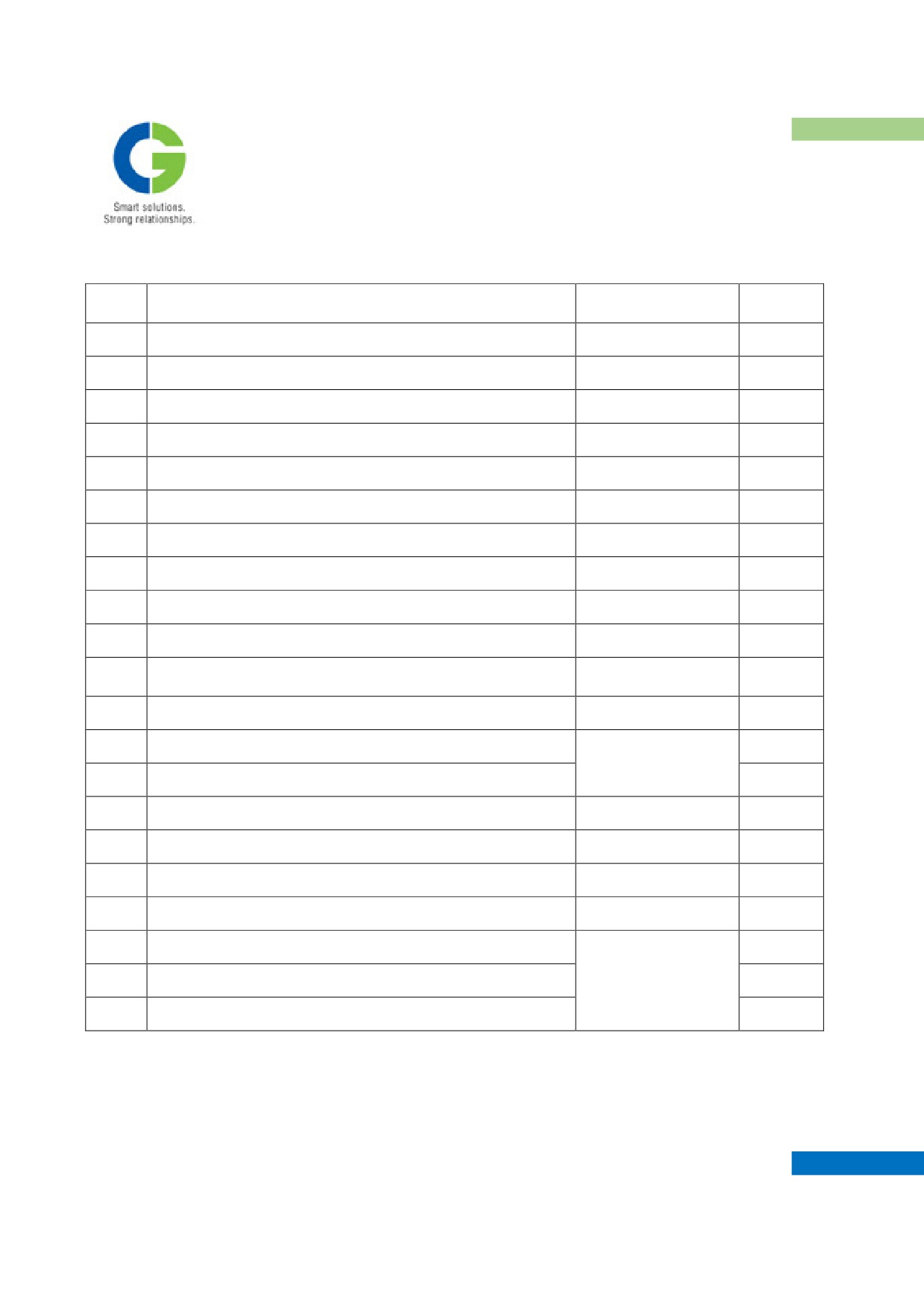
6. LIST OF COMPONENTS
Qty./Unit
S.No.
Item & Type
Manufacturer
(Nos.)
1
Rectifier Diode Type OSD 595 P 36SQ
RUTTONSHA
09
2
Rectifier Diode Type OSD 595 N 36SQ
RUTTONSHA
09
3
Heatsink Type HT350, 200 mm. long
RUTTONSHA
09
4
Hole Storage Capacitor 0.47 MFD / 2000 V
GE/ ICAR
18
5
Semiconductor Fuse 725A, 1000 V Type 170L 9598
BUSSMANN
09
6
Trip Indicator Fuse Type TI-1200
GE/BUSSMANN
09
7
Microswitch Type : 2K3B033018, 2 C/O
KAYCEE
18
8
Diode Type A3FMR160 for fuse blow supervisory circuit
RUTTONSHA
12
9
D.C. Contactor Type: MN022E - 110V.D.C Coil
L&T/ SIEMENS
02
10
Axial Fan Type A3G 400-BK13-P1 110VDC 0.45 KW
EBM PAPST
01
Potentiometer 10K, 1W, 10T (Type 3590) for fan speed
11
BOURNS
01
Control
12
Air Pressure Relay Type : GM-021-00-XB7-5
SWITZER
01
13
Resin Cast Current Transformer 1000 / 5A Type RCT01
01
GILBERT
MAXWELL
14
Resin Cast Potential Transformer 1000 / 125V Type RCT01
01
15
Fuse Link 2A , 415VAC Type NSD 2
BUSSMANN
01
16
AC Damping Capacitor 25 MFD / 660 V
ICAR / GE/ YASH
12
17
DC Damping Capacitor 10 MFD / 500 V
ICAR / GE
04
18
Earthing Capacitor 0.1MFD 1200VAC Type FMD 52
El-Ci_Ar
24
19
AC Damping Resistors 5 Ohm / 300 Watts W/W
03
IRESCO/PEC/
20
DC Damping Resistor 2 Ohm / 200 Watts W/W
SURE/ KIYOSH
01
21
DC Damping Resistor 50 KOhm / 50 Watts W/W
01
MAINTENANCE MANUAL FOR DETC-US
POWER RECTIFIER
NOTES
----------------------------------------------------------------------------------------------------------------------------------------
----------------------------------------------------------------------------------------------------------------------------------------
----------------------------------------------------------------------------------------------------------------------------------------
----------------------------------------------------------------------------------------------------------------------------------------
----------------------------------------------------------------------------------------------------------------------------------------
----------------------------------------------------------------------------------------------------------------------------------------
----------------------------------------------------------------------------------------------------------------------------------------
----------------------------------------------------------------------------------------------------------------------------------------
----------------------------------------------------------------------------------------------------------------------------------------
----------------------------------------------------------------------------------------------------------------------------------------
----------------------------------------------------------------------------------------------------------------------------------------
----------------------------------------------------------------------------------------------------------------------------------------
----------------------------------------------------------------------------------------------------------------------------------------
----------------------------------------------------------------------------------------------------------------------------------------
---------------------------------------------------------------------------------------------------------------------------------------
MAINTENANCE MANUAL FOR DETC-US
CHAPTER VII
TRACTION MOTOR
1. GENERAL INFORMATION
2. TECHNICAL DATA
3. CONSTRUCTION
4. ERECTION AND COMMISSIONING
5. MAINTENANCE AND INSPECTION
6. RECONDITIONING AND REPAIRS
7. MAINTENANCE SCHEDULE
8. TROUBLE PHENOMENON AND REMEDIES
9. INSPECTION SCHEDULE
Maintenance Manual
DIESEL ELECTRIC TOWER CAR | UNDER SLUNG TRANSMISSION
TRACTION MOTOR
CHAPTER VII
TRACTION MOTOR
1. GENERAL INFORMATION
The traction motor type TM2141C is a four pole self ventilated machine with a built in fan for DEMU / DETC
(Diesel Electric Multiple Unit / Diesel Electric Tower Car) Application. The machine is mounted on the Axle
with the help of taper roller suspension bearings. The general information about the traction motor is as
illustrated below.
Model
:
TM2141C
Type
:
Self-Ventilated
Field
:
Series Field with Commutating Poles
Field Strength
:
100%
Continuous Rating
:
187 kW (input), 600Volts, 340 Amps,
1520Rpm, (100% Field Strength)
Application Rating
:
111 kW (Input), 327 Volts, 340 Amps,
(Continuous)
840 Rpm, 100% Field Strength
Reduction Gear
:
Single Reduction (91/20)
Clearance between Gear
:
140 mm
case & top of rail with new
wheel diameter.
1.1 FEATURES
- The tractive effort is transmitted from the traction motor to the axle through a single reduction gearing.
- The traction motor is of the Self-ventilation system with the built in Fan sucking air through the Filter
Ducting Arrangement.
- The traction motor is of four poles, series wound with commutating poles.
- The Armature and Field windings are of class 200 insulation.
- The tungsten inert gas (TIG) welding is used for connecting Commutator riser to Armature Coil Leads
for better reliability.
MAINTENANCE MANUAL FOR DETC-US
TRACTION MOTOR
2.
TECHNICAL DATA
The maintenance of the traction motor should be conducted with respect to the following technical data:
2.1
SPECIFICATIONS
a. Model number
:
TM2141C
b. Type-form
:
Enclosed, Self-ventilated type
Series excitation with commutating poles
c. Poles
:
4
d. Insulation Class
:
Class-H
e. Continuous Rating
:
187 kW, 600 V , 340 A, 1520 rpm
2.2.
RESISTANCE VALUES
:
At 20°C
At 115°C
Armature winding
:
0.0114 Ω ± 5% 0.0156 Ω ± 5%
Series field winding
:
0.0128 Ω ± 5% 0.0176 Ω ± 5%
Commutating pole winding
:
0.0084 Ω ± 5% 0.0115 Ω ± 5%
2.3
ARMATURE DETAILS
Core diameter
:
406.4 mm
Core length
:
330 mm
Brg. to Brg. distance
:
795.00 ± 0.20
(Outer face of Distance Collars)
2.4.
ARMATURE BANDING
Material
:
0.33TK x 25 wide (Glass Banding Tape)
Turns on PE winding
:
100 Nos. Approx.
Turns on CE winding
:
100 Nos. Approx
MAINTENANCE MANUAL FOR DETC-US
TRACTION MOTOR
2.5
ARMATURE BEARINGS
Pinion side
Commutator side
Type of bearings
:
NU324EMC4
NH314EMC4
Manufacturer
:
SKF/FAG
SKF/FAG
or Equivalent
or Equivalent
Radial clearance of free
:
0.125/0.165mm
0.090/0.125mm
bearing when new (internal)
2.6.
COMMUTATOR
Diameter when New
:
280 mm
Minimum usable Diameter
:
260 mm
Mica thickness
:
1.0-mm nominal
No. of Commutator Bars
:
200 Nos.
Avg. Voltage between bars
:
12 V.
Reactance Voltage
:
2.3 V at Cont. Rating
3.8 V at Max Speed, Max Voltage Point
2.7.
CARBON BRUSHES
Numbers per brush holder
:
2.
Brush grade
:
EG14D
Brush type
:
Split
Brush size
:
20 mm x 40 mm Split x 57 Lg.
Brush spring
:
Max.3.2kg/brush
Pressure
Min.2.8kg/brush
Brush wear limit
:
Brush rejection length is 32 mm
2.8.
BRUSH HOLDERS
Number per motor
:
4
Clearance bottom of brush
:
3 mm Nominal
holder to commutator
Sparking tip gap
:
Adjustable, Nominal 12mm
2.9.
POLE BORES (AVERAGE)
MAINTENANCE MANUAL FOR DETC-US
TRACTION MOTOR
Main pole
(at center)
:
420.12 mm (Nominal air gap = 6.86mm)
Commutating pole (at center)
:
412.20 mm (Nominal air gap = 2.90mm)
Tolerance allowed on the Pole Bore Dim is ± 0.2 mm.
2.10.
LINER AT BACK OF POLE
Main pole
:
1.0-mm nominal (Magnetic steel)
Commutating pole
:
4.6 mm brass + 2.1 Mag. Steel
2.11.
GEAR CASE
Initial charge of Lubrication
:
6.5 Kg Max.
3.5 Kg Min
Type of Gear-case compound
:
HP Gear tak 2. or
Bharat Camex Compound .F
2.12.
WEIGHT
Motor with pinion
:
1800 kgs.
Armature
:
600 kgs.
Gera Wheel
:
150 kgs.
Gear case
:
90 kgs.
MAINTENANCE MANUAL FOR DETC-US
TRACTION MOTOR
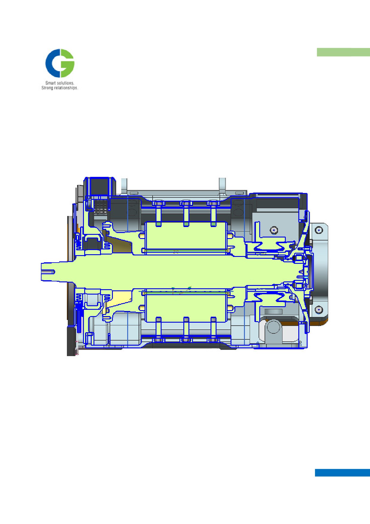
TRACTION MOTOR TYPE TM2141C
LONGITUDINAL SECTION DRAWING
MAINTENANCE MANUAL FOR DETC-US
TRACTION MOTOR
3.
CONSTRUCTION
The basic construction of the traction machine is illustrated in the Longitudinal section drawing indicating the
components used. The motor construction can be divided under the following heads.
1)
Armature
2)
Stator with coils & End-frames
3)
Suspension Bearing
4)
Gear-case, Gear, Pinion etc
3.1
ARMATURE
ARMATURE SHAFT
The shaft is manufactured & ground from Ni. Cr. Mo. Steel to BS 970 EN-25 "V" Bars forged material, which is
ultrasonically tested to avoid any flaws in the raw material for better reliability.
ARMATURE CORE
The Armature core is built up of coated electrical sheet laminations to reduce the eddy current losses.
ARMATURE END-RINGS
The Cast Steel Armature End-ring supporting the Core at pinion end has a mounted lightweight Fan for
ventilation. The material of the armature end-ring is forging for withstanding the load. The End-ring on the
commutator end is also manufactured from the Forged Material. The fan sucks the air from the commutator end,
which travels from the armature core through the End-rings & escapes from the openings provided on the pinion
end.
COMMUTATOR
The Commutator is built up with silver bearing copper Commutator bars with the alkyd vinyl bonded mica.
Commutator Hub & Commutator End-ring are of forged type. The anti-creepage PTFE Sleeves is fitted on the
exposed portion of the Steel Vee-Ring.
ARMATURE WINDING
The armature winding is lap wound type providing four parallel paths. The armature power coil conductors are
kapton-covered conductors for better performance. The armature is insulated & wound with class "H" insulation
material. The resi-glass banding at both the overhang portions is done with the banding machine under tension.
Complete wound Armature is subjected to Vacuum Pressure Impregnation (VPI) in solvent less polyester resin.
The Armature Coils are held in the slot portion with the help of slot wedges.
EQUALIZER WINDING
MAINTENANCE MANUAL FOR DETC-US
TRACTION MOTOR
The equalizer winding provides for 50 % Equalization.
ARMATURE BEARINGS
For the armature bearings installed at both commutator and pinion sides, a sealed type cylindrical roller bearing
with an additional advantage of intermediate grease refilling systen is employed. At the commutator side, Type
NHJ314EMC4 roller bearing is used and at the pinion side, type NU324MC4 is used. These armature bearings
can be operated for 3 years duration without dismounting.
ARMATURE BEARING COMPONENTS
The armature bearing-greasing labyrinth consists of forged bearing components accurately machined. The extra
firm variety felts are provided in the grooves of the end frames to prevent the lubrication leakage. The distance
collars at both the ends are shrink fitted, for the adequate location of the armature roller bearings. The grease
thrower at the Pinion end is shrink fitted outside the Bearing Cover P.E for protection against the ingress of
dust/Gear Case Compound.
3.2
STATOR
MAGNET FRAME
The magnet Frame is of casted type, with the terminal box provision for the main lead terminations. The frame
pole pads are machined accurately to avoid any variations in the pole bores thereby affecting the air gap. The
magnet frame is provided with a bracket for vertical mounting of Gear-case which also provides support to the
top half of Gear-case.
MAIN POLES
The main pole cores and coils are potted to the core with solvent-less polyester resin for better performance &
mechanical endurance. The Main Pole coil is of flat wound type with the frame side coil with 10 turns &
armature side coil with 9 turns. The coils are connected by brazing. The two open coils (N-pole) have the
terminals integral with them whereas the two crossed coils (S-poles) have terminals brazed with them. The main
pole field coils are of construction as illustrated in the fig.
COMMUTATING POLES
The Commutating pole core and coils are also potted with solventless polyester resin. The Compole coil is of 16
turns wound edge-wise. The terminals & connectors are of robust design to avoid the failures under
vibrations/impact. The Compole connections are made from the flexible cables.
BRUSH HOLDER AND CARBON BRUSHES
MAINTENANCE MANUAL FOR DETC-US
TRACTION MOTOR
This motor is 4-pole type motor and the brush holders are mounted on the frame pads by bolting arrangements.
The brush holders and carbon brushes can be inspected by inspection windows provided. The brush holders are
mounted on the frame pads by two insulating rods. The Brush Holders are manufactured from High tensile Brass
castings. The Carbon brushes of EG14D are of split type for smooth commutation.
END-FRAMES
The end-frames at both the ends are of Cast steel with the P.E. end-frame having the provision of integral arm
with the body for supporting the gear-case.
TERMINAL BOX
The terminal box has been provided in the centre location. The crossover line is fixed to the insulating rod and
lead supporter is used at the outlet of lead wires on the fitting-out side. On the reverse of the terminal cover, the
packing is stuck to prevent dust from coming into the terminal box. Four Main cables come out in the terminal
box which are connected in the sequence of A, AA, FF, F, E when viewed from the front with the Pinion side on
the right side & commutator side on the left.
3.3
MOTOR SUSPENSION ARRANGEMENT
The Motor Suspension on axle consists of taper roller bearings and suspension tube. The suspension tube
arrangement replaces the traditional use of axle caps & also avoids frequent maintenance. The use of taper-roller
bearings in the suspension arrangement allows the motor to run at high speeds.
3.4
GEAR CASE, GEAR WHEEL & PINION
GEAR CASE
The gear compound is filled from the inspection cover installed on the gear case. The Gear case is fabricated
type with the assembly in two halves i.e top & bottom half for ease in assembling & dis-assembling. The Top
half of gear-case is vertically supported and mounted on frame and end-frame arm PE. The bottom half is
horizontally bolted with frame and mounted on end-frame arm on PE side.
EARTHING LEAD ASSEMBLY
The earthing lead assembly is installed on the M8 tapped hole provided on the Magnet Frame.
GEARS & PINIONS
The gear & pinions are manufactured by BS 970 En 354 Case carborised steel conforming to RDSO Spec.
MP280009. The gears & pinions are machined in accuracy grade of 6 of BS 235:1987. The gear ratio of 20:91
has been adopted to suit the requirements of the Diesel Electric Multiple Unit application. The Bellow
arrangement provides the inlet for the air through the Commutator end, which escapes through the Pinion end.
3.5
EARTH BRUSH AND EARTH BRUSH HOLDER
MAINTENANCE MANUAL FOR DETC-US
TRACTION MOTOR
The earth brush holder is installed in the terminal box of the magnet frame. The earth brush is made of metallic
carbon and pressed to the axle by the coil spring.
4.
ERECTION AND COMMISSIONING
4.1
COMMISSIONING PRE-CHECKS
Before the motor is mounted on the bogie there are certain checks which need to be performed to assure a
reliable service in future. They are mentioned as underneath:-
4.1.1 LIGHT RUN OF MOTOR AT 1000 RPM
Subject the motor to a light run for 30 minutes to check that it runs freely and with quiet bearings. Also record
the Bearing temperature at both the ends. The vibration level of the motor should also be within the permissible
values of 30 microns.
IT IS NOT ADVISABLE TO RUN BEARINGS AT HIGH SPEED UNDER
LIGHT LOAD CONDITIONS FOR LONG PERIODS BECAUSE OF THE
POSSIBILITY OF ROLLER SKID, WHICH MAY CAUSE SCUFFING OF
THE TRACK AND ROLLER SURFACES.
The motor shall be subjected to a run at no load as per the test schedule & corresponding voltage & current shall
be recorded, the readings must be comparable to the values declared in the test results.
4.1.2 MEASUREMENT OF INSULATION RESISTANCE
The Insulation Resistance of the windings of the motor (complete) shall be recorded with 1 kV Megger. In no
case the IR Value should be less than 50 Mega-Ohms. In case the value is below the recommended value, the
individual windings should be separated & IR value of individual windings should be checked.
4.1.3 MEASUREMENT OF COLD RESISTANCE
The cold resistances of the different windings i.e. Armature, Main Pole and compole windings should be
measured with the help of the VI method and the variations in the values shall not be more than 5% of the
nominal prescribed values. The Armature winding resistance is measured across the 30 Commutator bars through
the inspection window and then the resistance so obtained is to be multiplied by (50/30) = 1.667 to get the
complete Armature winding resistance.
4.2 ASSEMBLY AND ERRECTION
MAINTENANCE MANUAL FOR DETC-US
TRACTION MOTOR
As regards the assembly of the various other components on the traction motor i.e. Gear case, Pinion and locking
plate, Earthing Brush assembly etc., refer to Reconditioning and Repairs. The Earth lead assembly is to be
fixed along with the copper washer & M8 bolt on the M8 tapped hole provided on Top of the Magnet frame.
5. MAINTENANCE AND INSPECTION
These checks are to be performed in the condition where the main motor has been installed on the truck.
5.1 BRUSH HOLDERS AND CARBON BRUSHES
The brush holder and carbon brush are important components in particular and have a great effect on
commutation. It is therefore necessary to always perform correct maintenance for obtaining normal operation.
If dust worn powders of carbon brush etc. enter between the holder case pocket and carbon brush and the motor
is operated in the sticking state of carbon brush poor contact with the commutator surface is caused and results in
poor commutation and/or flash-over from time to time. Therefore, in the check of brush holder, blow out the
holder case pocket with air and wipe with a dry cloth carefully.
Contamination of surface of insulating rod may cause a creeping short-circuit. So it should be cleaned by white
gasoline-infiltrated rag as frequently as needed.
In case that the surface of insulating rod has been roughened by flashover etc. correct with emery paper and
clean. If the surface is heavily damaged and cannot be corrected by emery paper and also, crack or seizure is
found in the insulating rod, replace with new one.
The carbon brush in the traction motor is tilted, clearance between holder case pocket and carbon brush increases
in the revolution. So, check to see as required that the pocket dimension of brush holder case and carbon brush
dimension are as specified. If the pocket is found worn beyond the maximum wear limit, replace it with new one.
The quality (material) and shape of carbon brush have a great effect on commutation therefore the specified one
must be used without fail. If any carbon brush of different material is used then, it may cause poor commutation,
unusual wear, damage of commutator surface etc. So never use any carbon brush made of different material from
that in use.
MAINTENANCE MANUAL FOR DETC-US
TRACTION MOTOR
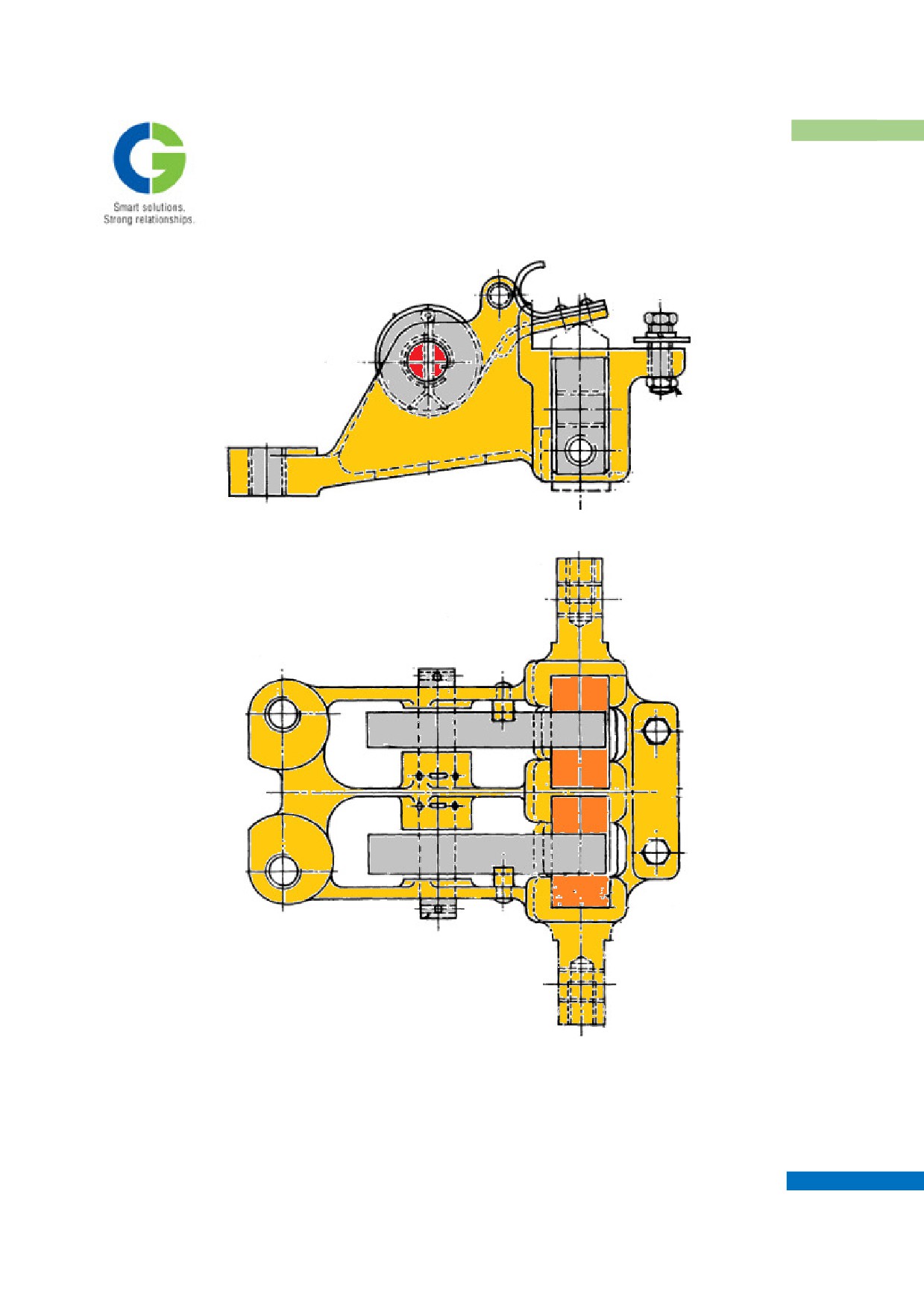
Brush Holder: Side view
Brush Holder: Top view
Check if the carbon brush has such length that it can be used sufficiently till the next check.
Check for Crack in the Carbon brush.
MAINTENANCE MANUAL FOR DETC-US
TRACTION MOTOR
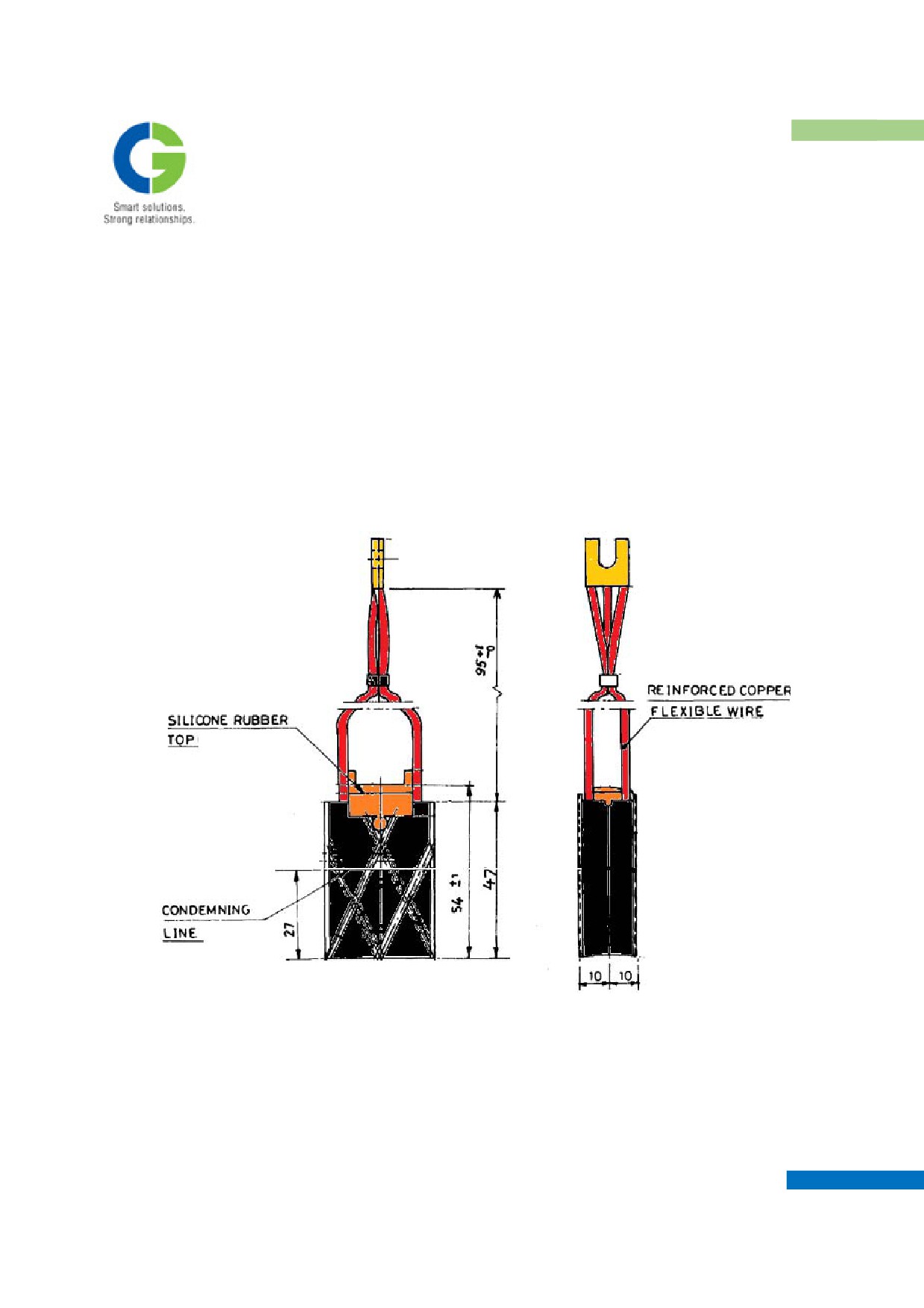
There shouldn’t be break of the pigtail (lead wire of carbon brush).
There shouldn’t be any looseness, drop-off etc. in the tamped part of pigtail.
The-carbon brush shouldn't be left seized in the holder case pocket.
Contacts of the carbon brush and commutator should be proper in condition.
If the carbon brush can no longer be used till the next check because of wear, replace it with new one. If the
dimension is found equal to 37 mm during the check of carbon brush, it may wear down to 32 mm-wear limit,
before the next check comes round. All such carbon brush should be replaced.
Carbon Brush
After inserting the carbon brush into the pocket of brush holder try to move the carbon brush up and down and
make sure that it moves smoothly.
When setting the brush spring after inserting the carbon brush into the brush holder be careful so that the lead
wire (pig tail) of carbon brush is not caught by the spring.
MAINTENANCE MANUAL FOR DETC-US
TRACTION MOTOR
When the worn out carbon brush has been replaced with new one, make slide fitting so that the carbon brush
contacts the commutator surface correctly. For making slide fitting of the carbon brush, move emery paper along
the commutator surface with the sand side of the emery paper applied to the brush and repeats this procedure a
few times.
HANDLE GENTLY IN MAKING SLIDE-FITTING TO AVOID DAMAGE
TO THE COMMUTATOR SURFACE.
After completion of the slide-fitting blow away brush powder with compressed air.
Tighten the terminal bolts of carbon brush lead wires securely.
The brush holders are fitted on the Magnet frame Brush gear mounting pads. Carbon brushes can be inspected
through the Inspection Cover openings provided on the frame. The latch type inspection covers provides access
to the brush holders.
DO NOT RELEASE THE BRUSH SPRING FROM HAND SUDDENLY
OR DO NOT DROP THE SPRING OFF THE SPRING SUPPORT. THIS
MAY BREAK THE CARBON BRUSH.
5.2 COMMUTATOR
As long as commutator is operated in good condition a film with a certain luster is formed on the
commutator surface. However, if a brush made of different material is used or dust gets on the surface,
ideal film won’t possibly be obtained. Unless otherwise wear of the brush, rough surface of the
commutator, stepped wear of the commutator, etc. are caused, there is no need to be concerned about the
film on the commutator.
Moreover, if such abnormalities occur, perform the maintenance of commutator. Moreover, after turning
the commutator the gap between the commutator and brush holder shall be ensured by shifting the
support block for the brush gear assembly towards the commutator side along the oblong hole provided
in the support block and then ensuring the torquing of around 12kg-m.
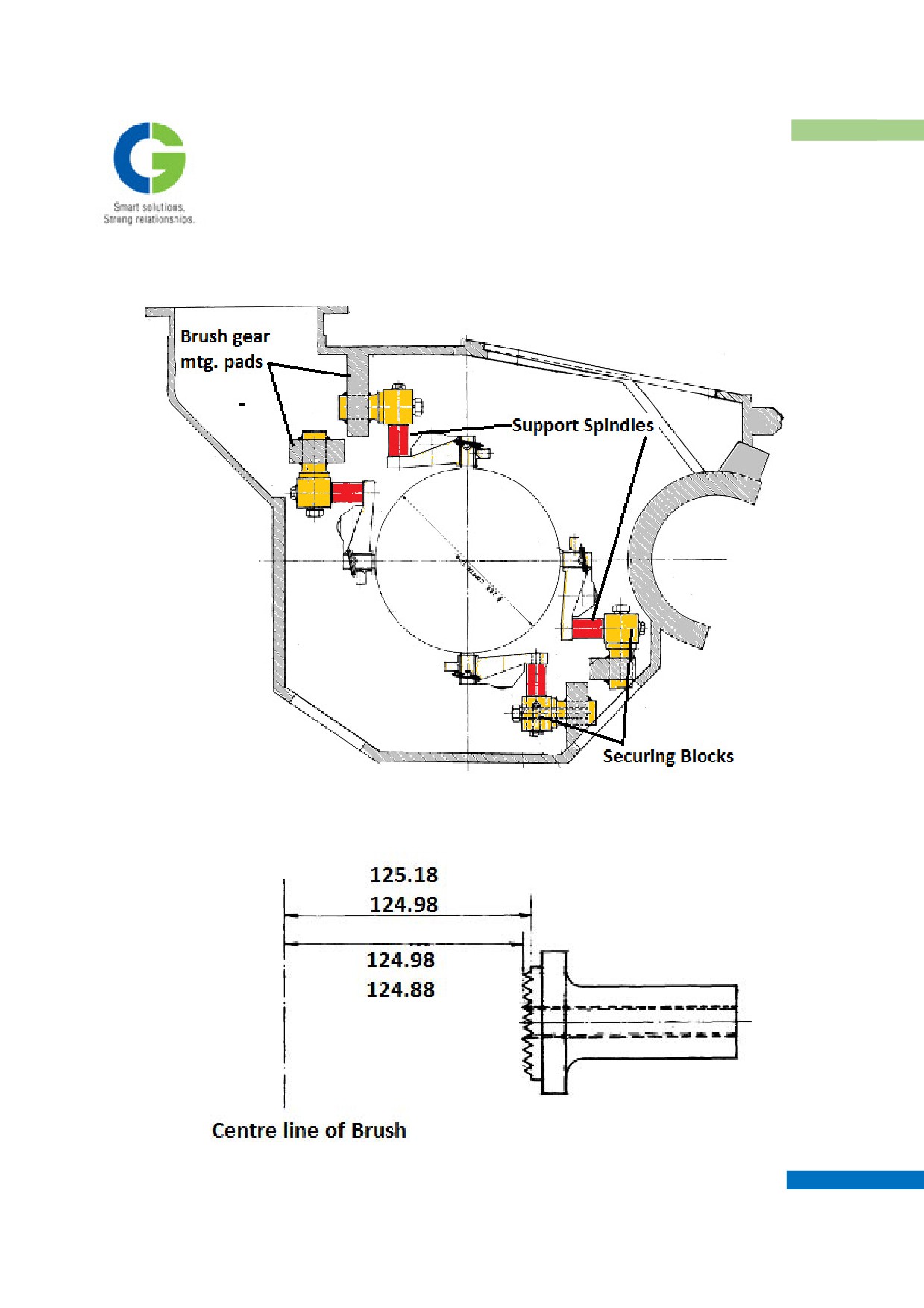
The securing block is welded on the brush gear mounting pads on the traction motor magnet frame
which become integral with the magnet frame. Also the securing block and the support block have
serrated faces (16 T.P.I) for ensuring proper grip.
The anti-creepage PTFE coated support spindles support the brush holders on the support block. Also the
MAINTENANCE MANUAL FOR DETC-US
TRACTION MOTOR
sparking tip arrangement is provided on the brush holders and end frames with a nominal gap of 12 mm.
The dimension of the center line of the carbon brush from the top of the serrations of the securing block
is critical and should be maintained as shown in the fig.
MAINTENANCE MANUAL FOR DETC-US
TRACTION MOTOR
5.3 GEARCASE AND LUBRICATION
The maintenance checks of gear case and gear lubrication oil should be made placing importance on the
following aspects:
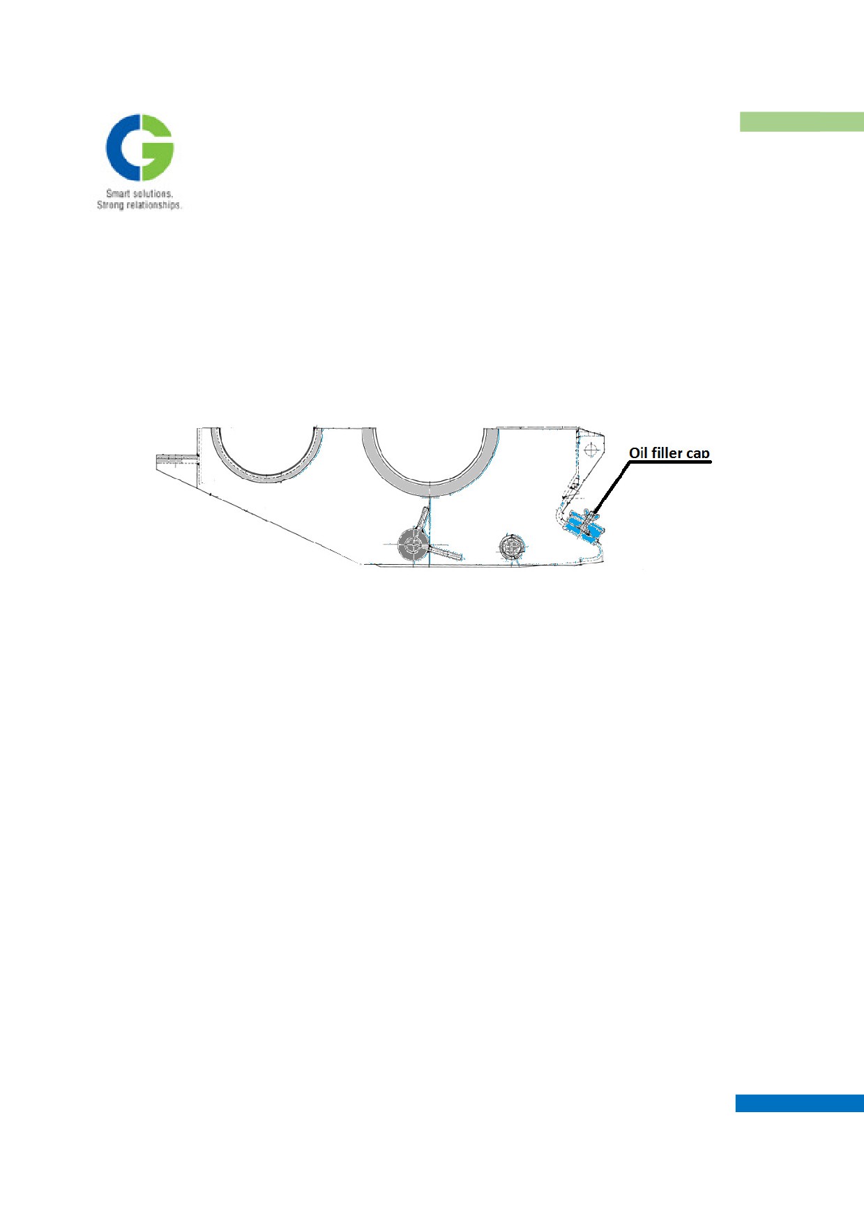
Open the Oil filler cap & check the Gear compound level.
Gear Case - Bottom half
When checking the Gear Compound level, if it is checked immediately after stop of the train, it will be
felt as if the gear compound is short. So, check the level after 20 to 30 minutes have elapsed, so that the
complete compound collects in the Gear case.
When supplying the compound, heat it to 60 - 80 °C (so that it can flow smoothly)
After the gear oil has been supplied, keep it for 20 to 30 minutes with the motor left in its stationary
state, and then check the compound level.
Check to see that there is no leakage of the gear compound. If any leakage of the gear compound is
discovered or consumption of the compound is considerably heavy, the felt sealing of gear case might
have worn off. So, check for drop - off of the sealing by removing gear case.
Check for obstructions of the breather. If it is discovered clogged with something, blow it out with air.
MAINTENANCE MANUAL FOR DETC-US

TRACTION MOTOR
Gear Case - Top half
Check for looseness of the gear case mounting bolts and for cracks in the gear case.
5.4 GEARCASE CHECKING
During the first few weeks in service, check the level of lubricant every week on several vehicles
and look generally for any sign of leakage. All checks should be carried out with the Gear case
warm after a run, but after allowing a short period to settle the lubricant. Continue these weekly
checks until the lubricant level has fallen to the minimum permissible as indicated by the dipstick,
note the time lapse. The shortest time interval on the representative batch of vehicles may be used
as a basis for the lubrication schedule, after allowing a safety examination. Thus, if the shortest time
interval is two months, specify topping up at monthly intervals.
5.5 ARMATURE BEARINGS
Since the armature bearing is an important mechanical part, it must always be kept in good
lubricated state. For this, a regular maintenance is essential. In the routine check, check for unusual
sound, oil leak etc. during rotation of the bearing and re-supply grease every year. At the time of
overhaul, exchange the whole grease.
SOUND OF BEARINGS
a. In the operation, always pay attention to the working sound of the traction motor and if any
unusual sound and/or vibration are observed, stop the operation immediately, dismount the motor
and look for the real cause carefully.
b. When the traction motor is removed from the truck be sure to perform the running light test of the
motor and check for unusual noise. Check for the noise applying a noise detector bar to the outside
MAINTENANCE MANUAL FOR DETC-US
TRACTION MOTOR
of side cover nearest the bearing at both pinion and commutator sides. In this case even for other
few motors check for noise. When comparing the working sound of these motors with each other, it
can be judged easily whether the sound is different from the usual one.
5.6 REFILLING OF GREASE
a. The grease to be refilled intermediately should be of the same kind as that used
in assembly.
b. The intermediate refilling intervals and the amount of grease refilled should be
as described in the Chapter Reconditioning and repairs.
5.7 EXAMINATION OF GEARS
Whenever a gear case is removed from a motor, examine the gears carefully. They should be coated
uniformly with lubricant, which should show no sign of being contaminated with dirt or water.
If the gears are to re-enter service immediately clean thoroughly using xylol or a similar solvent
applied with a brush. Wipe with a cloth afterwards. If the gearwheel is likely to stand for a time,
clean only ten to twelve teeth spaced equally round the periphery, leaving lubricant on the reminder
of the gearwheel as protection. After examination, if the condition of these cleaned teeth is
satisfactory, recoat them with gear compound.
The teeth should be free from cracks and the flanks should have a uniform, unscored polished
appearance. The tooth profile should be substantially the same as that of a new gear. If a gearwheel
has chipped, broken or badly worn teeth discard it and fit a new gearwheel.
Ensure that, as far as possible, gearwheels are returned to service with the pinions with which they
were meshed originally. Do not over fill the gear case, which may flood the PE armature bearing
and cause premature bearing failure. Use the opening provided on oil filler unit for measuring the
maximum lubricant level.
ENSURE ALSO ON NO ACCOUNT, LUBRICANT LEVEL GOES BELOW
THE MINIMUM LEVEL. USE DIPSTICK FOR MAINTAINING
MINIMUM LEVEL.
Gear and pinion is to be critically examined before allowing them further for service.
PRECAUTIONS
Whenever a gear or pinion wears significantly there is step created near the root of the tooth where the
MAINTENANCE MANUAL FOR DETC-US
TRACTION MOTOR
tip of the mating tooth runs out of engagement. If the gear center distance is exactly correct, this step
will occur at the lowest point of contact between the mating teeth. However the gear center distance
cannot be controlled exactly in service due to axle bearing wear. As the gear center distance spreads, the
teeth become further out of alignment, this forms step at varying depths.
If the same gearings are used there will be very severe tip loading of the tooth and very poor profile at
the root end of the tooth. This can cause severe noise, vibration and premature failure. The step is to be
dressed up with the help of small hand grinder. Care should be taken during the grinding operation not
to under cut the tooth. Step should be removed before checking the profile of the tooth by profile gauge
otherwise faulty readings will occur.
GEAR TOOTH WEAR
Gear tooth wear is measured by scaling the width of the land or tip of the tooth. The gear wheel and
pinion should be removed from service when width at tooth tip or maximum wear per flank measures
less or more respectively than the following limits:
Gear Wheel
Pinion
Min Tip Width
Max. wear per
Min.Tip Width
Max. wear per
flank
flank
1.8 mm
1.8 mm
0.8 mm
1.8 mm
PROFILE DEVIATION LIMIT
The maximum profile error on any worn gear wheel when checked by a profile checking gauge should
be within 0.2 mm to 0.4 mm Gears/Pinions having more deviation in profile than above should not be
used.
Feeler gauges of .05, .1, .15, .2, .25, .3, .4 mm thickness may be required for this purpose. Profile
checking gauges can be made as per the instructions given below:
Instructions for Making Gear Tooth profile gauge (using a new gear as a pattern)
1. Be sure that the gear used as a pattern is new. The gauge can only be as accurate as the gear from which
it is made. The gear should be thoroughly cleaned before using as a pattern.
2. Make a "partial" mould. The gear itself will complete the mould.
3. Wax all surfaces, which will receive the moulding compound with silicone wax CP mould release. This
material is made by the Chemical Development Corporation 53 endicott St. Danvers, Mass U.S.A.
4. Lay the pinion or gear on a flat smooth waxed surface with the bore vertical. If a table is not available
make a flat plate and clamp it to the side of the gear or pinion.
MAINTENANCE MANUAL FOR DETC-US
TRACTION MOTOR
5. The pinions are made with tapered teeth that are the tooth is thicker at the outboard (small-bore) end
than at the inboard (large bore) end. The pinion should be laid on the flat surface, with the outboard
(small-bore) and face down. Thus the gauge will be moulded to fit the thicker end of the tooth.
6. Place the partial mould in position against the tips of the teeth. Make sure that all the surfaces that will
contact the moulding compound have been coated with wax as described. The partial mould and the
pinion should be clamped in position with "C" clamps to prevent anything from disturbing their position
during the hardening process.
7. Mix eleven (11) parts of Ren Die Surface Coat RP-3260-B with one (1) part of Ren die Surface Coat
Hardner RP-3260-B by weight. These materials can be obtained from Ren Plastic Inc. P.O. Box. 1256,
Lansing 4, Michigan, U.S.A.
8. This is a modified epoxy resin which has a pot life of about 30 minutes at room temperature after the
hardener is added.
OBSERVE THE PRECAUTIONS STATED ON THE CAN, ESPECIALLY
AVOIDING ANY CONTACT WITH THE SKIN.
9. Pour the thoroughly mixed resin into the mould until full. Allow the mould to set for several hours,
preferably 12 hours or more.
10. Remove the parts of the mould the pattern pinion or gear the partial mould and the plate, if one was
used. Care should be taken to slide the plastic off the end of the gear teeth so as not to disturb the
profile surface of the newly moulded gauge.
6.
RECONDITIONING AND REPAIRS
6.1
REMOVAL OF PINION FROM SHAFT
Two methods of pinion removal have been arranged
(1) Injection method
(2) Mechanical
The second method is intended to be used when the injection equipment is not available. When using the
injection equipment, it is not necessary to remove the armature from the magnet.
MAINTENANCE MANUAL FOR DETC-US
TRACTION MOTOR
a.
REMOVAL OF PINION USING INJECTION EQUIPMENT
This method is recommended for the withdrawal of the Pinion from the shaft, as it is superior to the mechanical
method of withdrawal.
Special Tools Required: Injection Equipment.
TO PREVENT PERSONAL INJURY, SOME LOCKING DEVICE/PLATES
SHOULD BE USED, TO RETAIN THE PINION AS IT RECOILS DURING
THE RELEASE PROCESS.
Couple up the injection equipment. Prime the pump with glycerine and continue pumping until the pinion
releases.
Disconnect the injection equipment from the shaft and remove the pinion. Blow out the holes in the shaft and
fit the plug for protection.
Glycerine is used by `Brush', but the standard recommended use is oil.
b.
REMOVAL OF PINIONS MECHANICAL METHOD
This method is not recommended for the Pinion withdrawal.
Special Tools Required: Withdrawal Tackle, Packing Peg, Hammer etc.
Attach the withdrawal tackle to the pinion, tighten the nuts on the studs and strike the release pawl with a heavy
lead hammer, tightening the nuts until the pinion releases.
IT IS NOT ADVISABLE TO STAND IN LINE WITH THE SHAFT
DURING WITHDRAWAL OPERATION SINCE THE RECOIL, WHEN
THE PINION IS RELEASED MAY CAUSE PERSONAL INJURY.
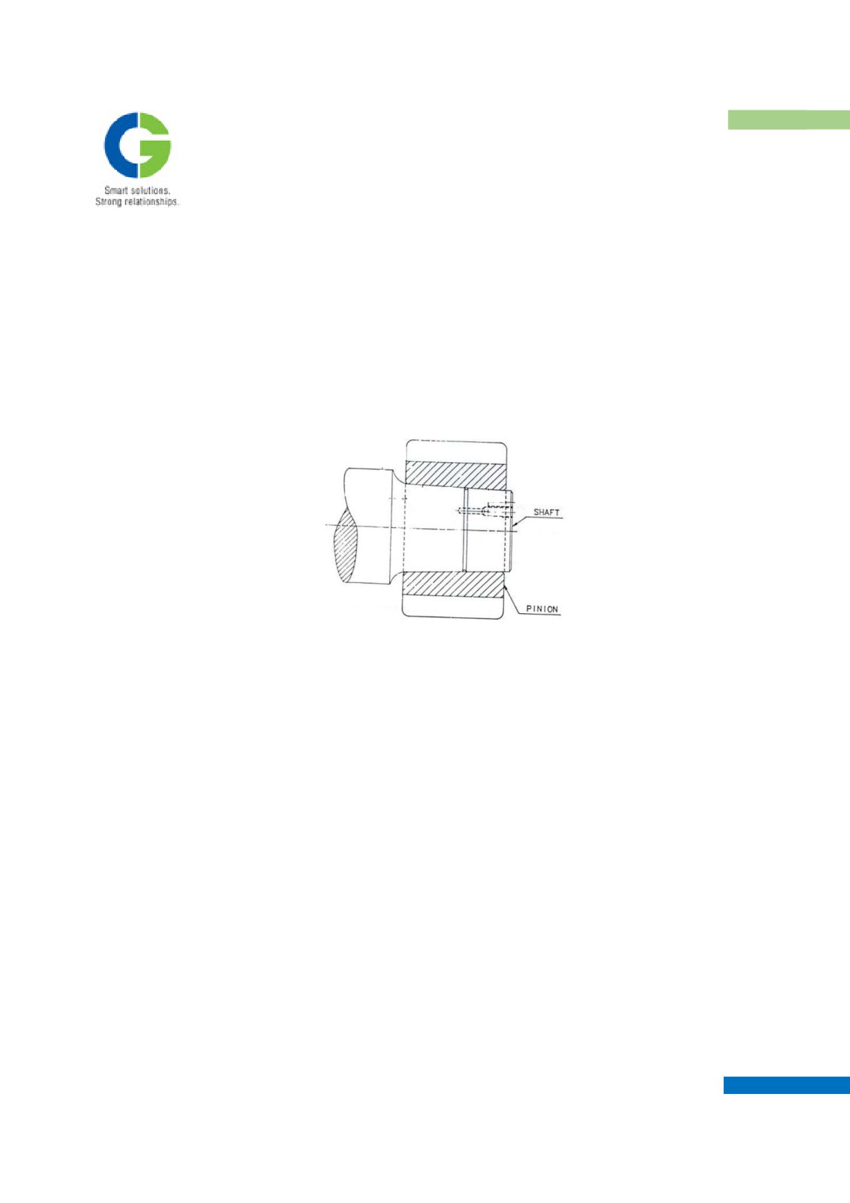
6.2
MOUNTING PINION ON SHAFT
When mounting the traction pinion on the shaft, great care must be taken and the following procedure should be
adhered to: -
MAINTENANCE MANUAL FOR DETC-US
TRACTION MOTOR
Ensure that the shaft and bore of the pinion are free from burrs and irregularities; these should be polished out
with grinding paste. Remove any sharp edges from the oil distribution channel on the shaft.
Thoroughly clean the injection holes and fitting surfaces with white spirit.
Check the bed of the fitting surfaces using a light smear of Prussian blue paste. A minimum of 85% bed
uniformly distributed is required and should be obtained without lapping. Remove the pinion and thoroughly
clean the bore and shaft.
Gently "feel on" the pinion ensuring that it is home on the taper.
Using suitable gauges, measure the dimension between the end of the shaft and the face of the pinion. Record
this figure for comparison purposes after final pinion fitting. Suspend the pinion in a thermostatically controlled,
free circulating oven or use Induction Heater to attain the above temperature on Pinion Bore. Heat the pinion to a
temperature of 140 °C to 160 °C above ambient, for at least 6 hours in the Oven.
Remove the pinion from the oven, quickly wipe the bore clean and slam the pinion on the shaft. Allow the shaft
and pinion to cool to room temperature. Measure the distance from the end of the shaft to the face of the pinion
and subtract this dimension from the one previously recorded. The figure obtained is the advance of the pinion
along the taper and must fall between the limits 2.6 mm to 2.9 mm. If the correct advancement is not obtained,
remove the pinion and reheat, making the necessary temperature adjustment. Fit the nylon plug in the injection
hole.
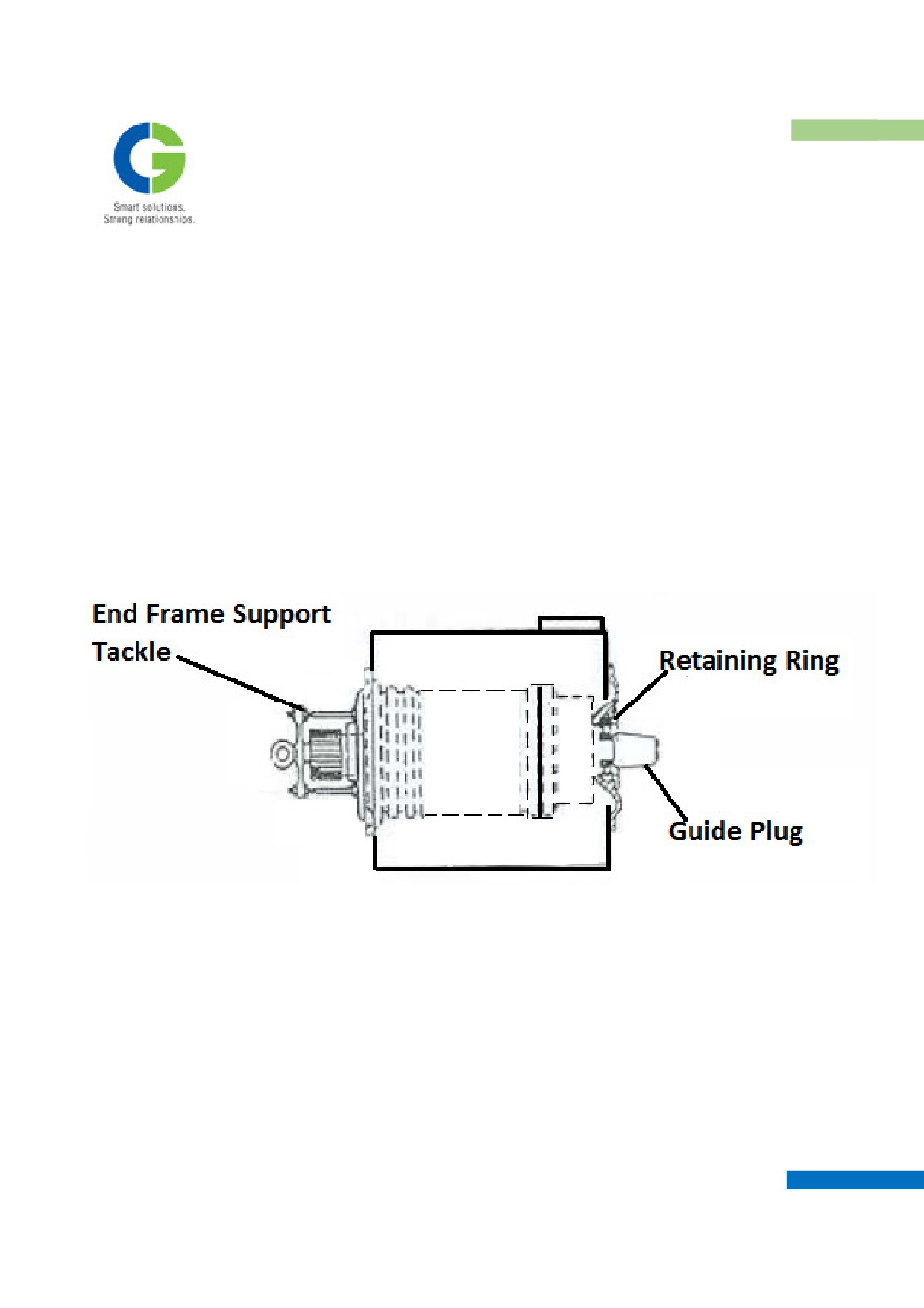
6.3 WITHDRAWAL OF ARMATURE FROM MOTOR FRAME
Special Tools Required:
• Outer Race Retaining Ring,
• Guide Plug
• End frames Support Tackle
Clean all external parts of the motor before proceeding to dismantle. Lift all the brushes and wrap suitable
protection around the commutator face.
MAINTENANCE MANUAL FOR DETC-US
TRACTION MOTOR
At the commutator end remove the bearing cap, using three M12 forcing off screws, the clamping plate, locating
ring and grease deflector.
Fit the outer race retaining ring and armature guide plug.
Fit the lifting eye adapter, End frame support tackle and the lifting eye. Turn the motor on end, commutator end
downwards, and rest it on suitable packing blocks. Using a spirit level accurately set the motor axis vertically.
Attach crane hook to the lifting eye and raise crane sufficiently to take up the strain.
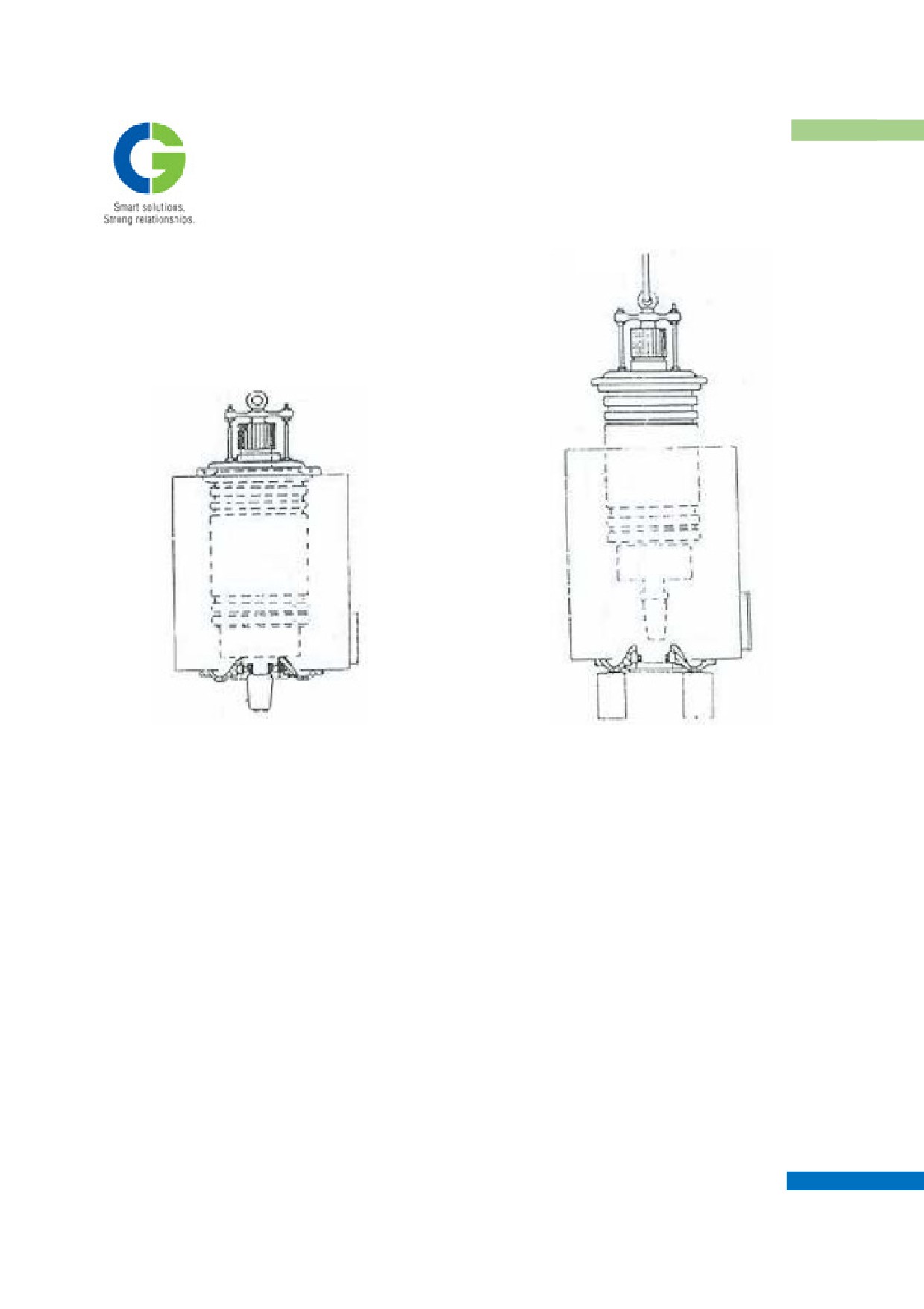
Unlock and remove the six M20 screws and lock washers securing the pinion end to the motor frame.
Use three M20 screws to jack the endframe spigot clear at the same time raise the crane to take the weight of the
armature.
When the end frame is clear of the motor frame, carefully lift the armature clear and place it horizontally on
timber blocks, approx. 350 mm high.
MAINTENANCE MANUAL FOR DETC-US
TRACTION MOTOR
Motor raised in vertical condition
Armature being lifted from Stator
6.4 EXTRACTION OF PINION END ARMATURE BEARING
Special Tools Required:
• Outer Race Bearing Withdrawal Tackle
• Race Bearing Withdrawal Tackle.
Withdraw the armature from the motor frame, using the procedure described in the previous section.
Dismantle the armature lifting tackle, and remove the pinion from the armature shaft, as described in the relevant
section.
Remove the bearing cover using two M12 forcing-off screws.
Release the grease thrower from the armature shaft using injection equipment.
Remove the grease deflector.
Slide the end frame off the armature shaft. The bearings outer race and roller cage will come away with the
housing, leaving the inner race on the shaft.
MAINTENANCE MANUAL FOR DETC-US
TRACTION MOTOR
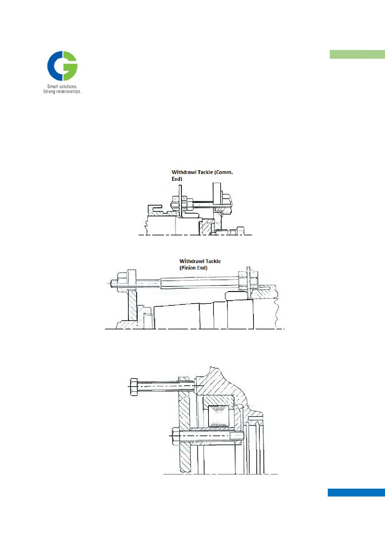
Fit the outer race withdrawal tackle. Ensure that the claws remain correctly located, while extracting the bearing
from the endframe, otherwise the rollers will be damaged.
To remove the bearing inner face from the shaft, the withdrawal tackle should be assembled as shown. Ensure
that the billets remain securely clamped in their correct positions while the withdrawal nuts are progressively
tightened.
Inner race removal (Commutator End)
Inner race removal (Pinion End)
MAINTENANCE MANUAL FOR DETC-US
TRACTION MOTOR
Outer race removal (Pinion and Commutator End)
6.5 ASSEMBLY OF ARMATURE BEARINGS
Ensure that the bearing housing of End frames is perfectly clean and free from caked grease etc. Check the felt
grease seals in the outer race pressing ring (PE), and replace if necessary. The felts must be cut accurately and
square (6mm x 6mm). When fitting, secure them in the grooves with Anabond binder or some adhesive. Allow
some time for the adhesive to set, then lightly oil the felt seals with lubricant.
NOTE: It is essential that the procedures referring to roller bearings be observed.
1. Fill the bearing housing cavity with grease.
2. Thump grease between the rollers and onto the cage at the back of the bearing.
3. Fit the bearing in to the housing with the identification marks facing outwards.
4. Ensure that the outer race is pressed right home to the locating shoulder.
5. To fit the inner race, heat it to 90 - 100 °C by immersion in an oil bath.
6. Ensure that the shaft seating is clean and unblemished and slip the race into position while hot.
7. The race to be fitted with identification marks outwards.
8. Hold the race in position against its distance collar until it has contracted sufficiently to grip the shaft.
9. Using a tabular drift, tap the inner race when at ambient temperature to ensure that it is hard up against
the distance collar.
10. The PE and CE distance collar may be machined in the assembled condition on the shaft to maintain the
perpendicularity and the bearing to bearing distance (see TECHNICAL DATA) for achieving limited
value of bearing run-outs.
RECOMMENDED BEARING GREASE FOR THE ARMATURE BEARINGS
1.
TYPE:-SERVOGEM RR3 OF IOC OR HP LITHION 3
QTY. OF GREASE (FOR INITIAL FILLING)
PINION END
:
0.400 kgs approx.
COMMUTATOR END :
0.165 kgs approx.
2.
REPLENISHING QUANTITY & PERIOD
PINION END
:
0.06 kg approx. (every 4 months)
COMMUTATOR END
:
0.03 kg approx. (every 4 months)
6.6 BEARING ASSEMBLY WITH END FRAME
Special Tool Required: Endframe Support Tackle.
MAINTENANCE MANUAL FOR DETC-US
TRACTION MOTOR
If it was necessary to dismantle the pinion end bearing, fit the Pinion end frame, with outer race and roller cage
assembled, on to the armature shaft, and carefully slide the rollers on the inner race. Thump grease between the
rollers and onto the cages at the front of the bearing.
Fit the grease deflector and pack the space between bearing and deflector with grease.
Heat the grease thrower to 125 °C above ambient and fit it on the shaft to abut against the bearing inner race.
Retain the grease thrower in this position until it has cooled. Ensure that the bearing cover is clean and the grease
drains clear. Apply ‘jointex’ sealing compound & packing (Nitrile Rubber) to the joint faces of the endframe and
bearing cover and secure the cover with M12 screws and spring washers. Fit the endframe support tackle and
lifting eye.
6.7 ARMATURE ASEMBLY INTO MOTOR FRAME.
Special Tools Required:
• Outer Race Retaining Ring
• Guide Plug.
1. Fit the CE endframe spigot, with outer race and roller cage assembled, in to the motor frame.
2. When the end frame is fully - home, secure with M20 screws and bend the locking washers.
3. Fit the outer race-retaining ring to the End frame.
4. Turn the motor frame on end, commutator end downwards, and rest it on suitable packing blocks using a
spirit level, accurately set the motor axis vertically. Fit the armature guide plug to the shaft. Attach a
crane hook to the lifting eye on the armature and lift the armature to a vertical position.
5. Carefully lower the armature into the motor frame, ensuring that the rollers do not damage the inner race
at the commutator end.
6. When the pinion end frame spigot enters the motor frame, pull it fully home by means of the five M20
fixing screws secure the screws by use of locking washers as shown.
7. Carefully turn the motor to the horizontal position, and remove all tools and lifting tackle.
8. At the commutator end, thumb grease between the rollers and into the cage at the front of the bearing.
Fit the grease deflector and locating ring, and fil the cavity between this and the grease deflector with
grease.
9. Secure the clamp plate to the shaft with the M12 screws and locking plate and turn up the corners of the
plate.
10. Fill the outer bearing cap with grease, and apply `Jointex' sealing compound to the joint Surfaces of the
bearing cap and End frame.
11. Secure the cap with M12 screws and spring washers.
MAINTENANCE MANUAL FOR DETC-US
TRACTION MOTOR
12. Remove protection from around commutator face lower the brushes and check bedding. Mount the
pinion on the shaft, using procedure described.
6.8 REMOVAL OF BRUSH GEAR ASSEMBLY
1. Lift the springs and support them on the cylindrical pins on the Brush Holder body. Now remove the
pigtails of the brushes from the Brush holder by loosening the screws then carefully remove the carbon
brushes.
2. Remove Screws and washers from the brush holder mountings and detach the cable terminals from the
brush gear.
3. Remove Screw and washer and detach the brush gear assembly (excluding the Securing block, which is
welded on the frame pads) from the magnet. When the new Brush Gear Assy is mounted on the frame it
should be borne in mind that the brush holder pocket centre line exactly coincides with the main pole
centre lines.
4. Unlock and remove the Screws and spring washer securing the insulating support spindles with sleeves,
to the support block.
5. Remove the insulating support spindles from the brush holder. The support spindles (insulating rods) are
fixed in the support block counter bore dia for better grip.
6.9 ASSEMBLY OF BRUSH GEAR
To assemble the brush gear to the magnet frame as per procedure explained above but in reverse order. Ensure
that the insulating rods are clean and dry and the set screws are secured.
Remove protection from around commutator face.
Fit and lower the carbon brushes and retains them with the pressure springs. Also screw the pigtails of the
Carbon brushes on the provision made on the Brush holder body. Carry out the bedding of the brushes, as per the
standard practice followed in the Conventional Motors of Railways.
6.10 REMOVAL OF FIELD POLES FROM MAGNET FRAME
The main pole coils and interpole coils are resin bonded (Potted) onto their respective pole bricks, & if required
to be replaced, must be essentially replaced by a wound brick assembly.
MAINTENANCE MANUAL FOR DETC-US
TRACTION MOTOR
DO NOT DISTURB THE POLES AND CABLES UNLESS
ABSOLUTELY NECESSARY. BEFORE DISTURBING THE POLES,
MEASURE AND RECORD THE MAIN POLE AND INTERPOLE AIR
GAPS TO ENSURE THAT THE MOTOR IS REBUILT WITH THE
ORIGINAL GAPS.
The air gap is half the difference between the armature and pole face diameters. The tolerance allowed on the air
gaps (armature side) is ± 5 % approx. from the nominal value Remove the insulation tape from the coil
terminals. Remove the set screws and washers and detach the cable terminals. Remove the set screws and
washers and detach the poles.
6.11 ASSSEMBLY OF FIELD POLES FROM MAGNET FRAME
ENSURE THAT THE MAIN POLE ON THE SUSPENSION TUBE
SIDE IS MOUNTED WITH SPECIAL REDUCED HEAD BOLT. ONLY.
Also proper recommended torque level should be applied on the Main pole & Compole mounting bolts. Also,
proper recommended torque level should be applied on the M.P. and C.P. Mounting bolts. After assembly,
mounting bolts shall be locked with the help of the rectangular locking pieces in the counter bore dia. & then the
RTV compound should be filled to avoid any dust ingress through the counter bore area.
Secure the main poles and interpoles in their correct positions in the magnet frame, with Mounting Bolts and
washers. Measure the armature air gaps and ensures that the dimensions previously recorded are maintained and
the pole spacing equalized. When the poles are correctly positioned and secured, tack weld the locking bar in the
counter bore to lock the Main Pole & interpole Mounting Bolts.
Secure the cable terminals with Screws and washers
(Plated only), and tape the terminals with Silicon rubber
Tape - two layer half lap to overlap the cable insulation by 50 mm followed by one layer half lap glass tape. Now
shrink the Silicon Rubber tubes on the exposed portions. Apply insulating varnish over the connections and
cable. Check the cable insulation with a 1000-volt Megger. This should not be less than 2 Megaohms when cold.
Check field system polarities with a compass.
MAINTENANCE MANUAL FOR DETC-US
TRACTION MOTOR
CABLES AND CONNECTIONS MUST BE INSULATED FROM EACH
OTHER AND HELD CLEAR OF THE ARMATURE.
6.12 REMOVAL OF GEAR CASE
1. Remove all the old lubricant and dirt from used gear case with a steam lance or a caustic solution.
2. Do not burn gear compound from the Gear case as warping will result.
3. Rinse the Gear case thoroughly in boiling water to remove all traces of caustic solution.
4. Dry and repaint the Gear case.
5. Renew all felt seals.
6. Check that the two halves of the Gear case fit together, that is the groove in the top half fits over the
groove of the bottom half and that the semi-circles of each opening are in reasonable alignment.
7. If the two halves do not fit together properly it may be because they were not originally assembled and
machined together.
8. Each half of Gearcase is stamped with the same number.
9. Check these numbers (the number will be found at the pinion end of the Gear case on the road wheels
side, near the horizontal joint).
6.13 ASSEMBLY OF GEAR CASE
1. Lift the bottom half gear case up around the gearwheel until the felt seals around the motor shaft opening
and the axle openings rest on the bearing cap and gearwheel hub respectively.
2. Insert one M36 mounting bolt, fitted with new lock washers, and screw down to support the gear case,
but do not tighten.
3. Heat about 3.5 kg of gear lubricant to about 85 °C and pour it over the pinion and gearwheel or
alternatively paint this lubricant onto the teeth.
4. Lower the top half Gear case over the gears until the felt seal rests on the bearing cap and insert and
screw down the M30, M36 mounting bolt. Do not tighten bolt.
5. Fit two M30 joint bolts and nuts, using new lock-washers and tighten with torque value at 35 kg-m.
6. Tighten the two M36 mounting bolts at specified torque of 65 kgm.
7. Top up Gear case with lubricant-use dipstick.
MAINTENANCE MANUAL FOR DETC-US
TRACTION MOTOR
7. MAINTENANCE SCHEDULE
Maintenance scheduling is very important and critical for the efficient performance of the electrical machines.
During periodical inspections, incipient faults or defects can be located and rectified. Such attention definitely
reduces the cost of repair and lengthens the life of the equipment. The most suitable intervals between service
maintenance occasions can only be determined by actual service experience. Initially, the intervals should be as
specified until it becomes possible to change them as experience is gained. In the case of lubricants, the
quantities and frequency of lubrications specified should similarly be treated as guide only. The actual interval
between lubrication and quantity of lubricant should be determined from experience and individual duties of
each machine.
A complete history of each machine, detailing the maintenance effected, lubricant consumption, list of renewals,
replacement etc. is therefore of the utmost importance and is thus advised to maintain such records.
7.1
PUTTING INTO SERVICE
After putting new or reconditioned machines into service for the first time, the following checks should be
carried out, during or at the end of first week of operation:
Check that after the motor has been mounted backlash exists between pinion and gearwheel. New gears are
manufactured to have a nominal backlash of 0.2 to 0.7mm, as measured on the outer i.e. non-relieved end of the
gears.
Check tightness of all bolts, particularly axle caps, gear case and brush gear bolts. Examine commutator and
brush gear and check that skin on the commutator is being formed and carbon brushes are bedded correctly.
Check that after a load run, temperatures of axle Suspension Taper Roller Bearings are not excessive.
Check for leaks of gear lubricant. Measure and record gearcase compound.
7.2
ROUTINE MAINTENANCE
a.
Monthly
1. Before removing the commutator covers, brush off loose dust or dirt.
2. Examine the commutator and clean the outer, have a well-polished surface and free from bar marking or
bar edge burning.
3. Remove any copper beads from the commutator surface with fine carborundum cloth. Deposits from
dirty or greasy hands should be removed by a solvent.
4. Examine the brush gear and clean the insulating rods.
5. Checks that the brush springs sit correctly on the brushes and that the springs are in good condition.
6. Check carbon brushes for wear.
7. Fit new brushes in place if any brush is unlikely to last until the next inspection.
8. See the Technical Data for minimum length and brush grade.
9. Bed all new brushes to the curvature of the commutator.
MAINTENANCE MANUAL FOR DETC-US
TRACTION MOTOR
10. Check the brushes for mechanical damage, breakage of flexible, etc. Fit new brushes if necessary.
11. Check that the flexibles are firmly secured to the brush holder.
12. Check brushes for freedom in the brush-holder and if stick ring cleans both the brush and
13. the brush-way in the holder.
14. Do not soak the brush, as the solvent will eventually ooze out, affecting the commutator and causing the
brush to jam in the holder.
15. If the brush appears to be excessively slack in the brush-holder, check the brush size and discard
the brush or the holder as the case may be.
16. If brush holders have to be removed from the machine, slip thin; clean press board between each brush-
holder and the commutator to avoid damaging the commutator surface.
17. On replacing brush-holders check the clearance between the underside of the brush-holder and the
commutator. See Technical Data.
18. Look carefully for any signs of flash over, overheating, loose connections or damaged insulation.
19. Top up Gear case to the level of gear oil filler unit. See Technical Data for Grade of lubricant.
20. Top up axle Suspension bearing Grease - See Technical Data & Suspension unit arrangement
Assembly & Disassembly for grade of grease.
b.
Three monthly
1.
Monthly service plus blow out machines using clean dry compressed air.
2.
Take particular care to direct air under the commutator in order to remove dirt lodged in the armature
core ducts.
3.
Check tightness of all brush gear bolts.
4.
Check tightness of bolts securing Suspension Tube and gear case.
5.
Check air inlet bellows for cracking tearing or collapsing. Renew if necessary.
6.
Check for leakage from the Gear case and Axle caps. Top up the bearings with the recommended
quantity of bearing grease. Top the roller suspension bearing with grease.
7.
Top the armature bearing with grease. Refer to the recommended quantity of the bearing grease.
c.
Six Monthly
Three monthly services plus: -
Clean outlet provided on PE End Shield in bottoms.
d.
Annually
Six monthly services plus:-
1.
When motors are removed from bogies for wheel turning etc. clean pinion and gearwheel and check for
tooth wear.
2.
Before fitting the gear cases, clean out old lubricant to avoid the possibility of gears running
subsequently in contaminated lubricant.
e.
Overhaul-Three yearly
1.
Remove traction motors from the bogies for overhaul and run on no load at about 1000 rpm and check
for noisy bearing rough commutator, vibration and brush chatter.
2.
Dismantle the motor and clean the armature and field system. Dry out to remove any detrimental
MAINTENANCE MANUAL FOR DETC-US
TRACTION MOTOR
moisture.
3. After drying out, check the hot insulation resistance of the traction motor & if found more than 1 Mega
ohm applies a high voltage test at 1.5 kV.
4. Check the armature for open and short circuits by a commutator bar-to-bar test at 600 V.
5. Remove the brush holder from the machine. Clean and inspect for brush clearance in the holder-spring
pressure and damage Recondition as necessary.
6. If the field coils and connections are in good condition then dry paint the interior of machine with
insulating varnish such as E-233 red of Dr. Beck or equivalent. If the field coils require repair, remove
and recondition individually. Check the armature bearing details for damage & renew as necessary.
7. Inspect the shaft for damages to pinion and bearing seating and ensure that it is straight.
8. Inspect the armature for loose bands, solder throwing etc. Recondition as required. If the commutator is
worn or damaged, skim the commutator and undercut the mica. It should be ensured that the
Commutator is turned only upto the safe wearing depth diameter i.e. 260 mm
9. Varnish impregnates the repaired or reconditioned armature with the polyester VPI Resin FT2005 of Dr.
Beck.
10. Inspect the axle bearings for wear, distortion and cracks. Also ensure the intactness of the suspension
tube bolts.
11. At the end, dynamically balance the armature ensuring that the maximum unbalance does not exceed
3gm-mm, reassemble the machine and paint the exterior of the machine.
12. Run the machine on no load at about 1000-RPM for 120 minutes to ensure correct operation of the
bearings. When installing the motor in the bogie ensure that all bolts are tightened to the specified torque
values. Fill the Gear case with the correct lubricant to the maximum specified level.
13. After assembly with the bogie, run the motorized bogies for 240 minutes to ensure proper alignment of
the gears and proper seating of gear case felts over axle.
Initially, it is expected that the temperature of the areas near to the felts will go upto 100°C but, after
excess felt has been worn off, the temperatures of these areas will return back to normal temperature
zone of 50-60° C.
MAINTENANCE MANUAL FOR DETC-US

TRACTION MOTOR
8. TROUBLE PHENOMENON AND REMEDIES
TROUBLE
TROUBLE
POSSIBLE
PHENOME
INSPECTION AND REMEDY
PART
CAUSE
NA
Commutati
1.
Carbon
a. Grade or Form
Examine if different grade is used and inspect the actual brush
on
brushes
spring pressure, if some abnormality is found adjust as
Trouble
designated.
b.Excessive wear
Check for spring pressure, should be within specified limits
c. Chattering
Remove oxygenated film of commutator surface or change grade
vibration
of brush
d.Brush Sticking
Clean the brush holder pocket, check for any deformation in the
pocket, use a new carbon brush
e. Copper picking/
Machine is running over loaded for periods more than the
spotting
specified limits
f. Sticking of oil
Unequal oxygenated film causes excessive wear, replace with a
film
new one.
g. Unbalance of
Looseness of pig tail, insufficient contact of brushes with
brush current
commutator. Replace carbon brushes.
h. Brush wear
Lift up of carbon brushes causes spark and damage. Replace with
a new one.
2.
a. High-bar, low-bar,
Color change, unequal oxygenated film, abnormal wear of brush
Commutator
deformation, ovality
may cause the flashover. Polish commutator surface with lathe.
b. Joggle wear and
Wear of brush. Polish commutator surface with lathe
roughening of surface
c. Bad chamfering or
Reform
bad undercutting
d. Shorting of bar by
Inspect and clean
dust
and
foreign
material
between
grooves
e. Abnormal temp. rise
Color would change at abnormally high temperatures.
Examine ventilation and load.
f. Black bar
Adjust commutation
g. Vibration
Examine radial and lateral clearance of bearings. Vibration of
truck and unbalance of armature. Abnormality shall be adjusted
according to the maintenance data
MAINTENANCE MANUAL FOR DETC-US

TRACTION MOTOR
3.
Brush
a. Wear of inside
Big gap to brush worsens sliding performance. Measure
Holder
of carbon way
dimension, replace with new one.
b. Improper
Crookedness pitch, gap should be examined and adjusted.
attaching
c. Improper spring
Check pressure and adjust pressure as designated.
pressure
4.
Other
a. Inadequate condition
Color of commutator surface may be changed (ex. Black)
parts
of
riser, shorting of
armature coil
b. Invasion of dust,
Roughening of commutator surface. Machine commutator.
rain
Prevent invasion of water.
c. Wheel slip, skid
Change current limit
d. Over current,
Examine safety relay
Over voltage
Over
1. Bearing
a. Bruise, scratch, rust
Replace with new one
Heating
b. Improper quantity of
Replenish with new grease.
grease
Apply proper grease
c. Improper attaching,
Check attaching and adjust it.
fitting or clearance of
Check clearance and replace it with good one.
bearings
2. Coils
a.
Layer
short,
Find trouble part and replace it.
insulation breakdown
Other
1. Insulation
a.Insulation breakdown
Abnormality in megger
Trouble
of coil, commutator.
DC component shall be systematically examined so as to find
breakdown
Lead
wire.Inner
troubled part
connection,
brush
Repair the damaged parts according to insulation.
holder
Oil Leakage
1. Armature
a. Improper grease
Check the quantity of grease. Refer recommended quantity of
bearing
quantity
grease
grease
2. Gear case
a. Excess charge of gear
Check the compound
compound
b. Bad packing and
Replace with new packing and oil sealing.
compound sealing
MAINTENANCE MANUAL FOR DETC-US

TRACTION MOTOR
9. INSPECTION SCHEDULE
INSPECTION INTERVAL
REPAIR
INSPECTION
ITEMS
AND
LIMIT OR
TRIP
MONTH
THREE
SIX
YEARL
TWO
STANDARD
OPERATIO
LY
MONTH
MONT
Y
YEAR
N RANGE
LY
HLY
LY
1. TRACTION MOTOR IN GENERAL
a. Appearance in general
0
0
0
0
0
0
b. Attaching of Inspection cover
0
0
0
0
0
0
c. Loosening of bolts, damage of
0
0
0
lockwashers
0
0
0
0
d. Invasion of dust and water
0
0
0
e. Condition of lead wire, and cleat,
contact of
0
0
0
0
terminals.
0
0
0
0
f. Oil leakage of bearing
0
0
0
g. Grease adding to armature bearing
h. Grease adding to motor suspension
bearing
2. ARMATURE
2.1 Commutator
0
a. Diameter : 280 mm
a. 260 mm
0
b. Eccentricity
b. 0.03 mm
0
c. Inequality in diameter
c. 0.05 mm
0
d. High or low bar
d. 0.03 mm
0
e. Under cutting depth : 0.9 to 1.5
0
MAINTENANCE MANUAL FOR DETC-US

TRACTION MOTOR
INSPECTION INTERVAL
REPAIR
TRIP
MONT
THRE
SIX
YEARL
TWO
INSPECTION ITEMS AND
LIMIT OR
HLY
E
MONT
Y
YEARL
STANDARD
OPERATIO
MONT
HLY
Y
N RANGE
HLY
f. Chamfering sharp edge cutting :
0
0
0.3 mm
0
g. Width of riser : 20 mm
(excluding TIG welding)
0
h. Difference of voltage drop
between bars within 5%
0
i.
Dielectric
test
newly
manufactured
:
2,500 V/
1 min
Repaired : 1,500 V/1 min
2.2 Armature Coil
0
a. Cleaning
0
b. Interturn insulation test
2.3 Shaft, bearing and Pinion
a. Diameter of shaft bearing on
a. 120 + 0.05
0
pinion side : 120 mm
+ 0.03
b. Diameter of shaft bearing on
b. 70 + 0.04
0
commutator side : 70 mm
+ 0.02
c. Wrap of shaft (deflection of shaft
end)
c. less than
0
d. Taking off, cleaning, inspection
0.03 mm
and oiling of bearing
0
e. Interference fit shall be applied
to inlay of inner ring of roller
bearing and shaft of pinion side.
0
Temperature of heating
:
110
-
120º C
f. Interference fit shall be applied
to inlay of inner ring of roller
bearing and shaft of commutator
side
0
Temperature of heating
:
110
-
120º C
g. Radial clearance of the roller
bearing on pinion side
0
MAINTENANCE MANUAL FOR DETC-US