8 WHEELER DIESEL ELECRIC TOWER CAR WITH UNDERSLUNG TRANSMISSION. OPERATING & MAINTENANCE MANUAL (2019) - page 5
CONTROL GEAR EQUIPMENT
• Re-varnish insulation surfaces, other than porcelain.
• Clean metal support frames and covers, repaint if necessary
• Check resistance values to figures given "Data for Control Apparatus".
MAINTENANCE MANUAL FOR DETC-US
CONTROL GEAR EQUIPMENT
NOTES
---------------------------------------------------------------------------------------------------------------------------------------------
---------------------------------------------------------------------------------------------------------------------------------------------
---------------------------------------------------------------------------------------------------------------------------------------------
---------------------------------------------------------------------------------------------------------------------------------------------
---------------------------------------------------------------------------------------------------------------------------------------------
---------------------------------------------------------------------------------------------------------------------------------------------
---------------------------------------------------------------------------------------------------------------------------------------------
---------------------------------------------------------------------------------------------------------------------------------------------
---------------------------------------------------------------------------------------------------------------------------------------------
---------------------------------------------------------------------------------------------------------------------------------------------
---------------------------------------------------------------------------------------------------------------------------------------------
---------------------------------------------------------------------------------------------------------------------------------------------
---------------------------------------------------------------------------------------------------------------------------------------------
---------------------------------------------------------------------------------------------------------------------------------------------
------------------------------------------------------------------------------------------------------------
-------------------------------------------------------------------------------------------------
-------------------------------------------------------------------------------------------------
MAINTENANCE MANUAL FOR DETC-US
CHAPTER XI
DRIVING INSTRUCTION
Maintenance Manual
DIESEL ELECTRIC TOWER CAR | UNDER SLUNG TRANSMISSION
DRIVING INSTRUCTIONS
CHAPTER XI
DRIVING INSTRUCTIONS
1.
OPERATING INSTRUCTIONS FOR DRIVER
1)
Preparation of Vehicle for Service
The driver should be provided with a master controller key and driver's control key. Before taking
a train into service, the driver must check the following points.
1.1
Check that all sealed switches are in OFF position.
1.2
Insert driver's control switch (DCS) key in Driver's Control Switch box (BL box) and turn in ON
& OFF.
1.3
Insert the master controller key and operate FORWARD & REVERSE and keep it in the OFF
position.
1.4
Switch on 24-Volt DC Battery isolating switch in the engine room.
1.5
Switch on 110 Volt DC battery isolating fuse switch behind driver's seat.
1.6
Switch on both battery voltmeter switches and check for
i) Starting battery voltage reads 24V
ii) Control battery voltage reads above 88V
1.7
Switch on all MCBs (control and auxiliary) except rectifier blower motor MCB
i) Switch on 110 V MCB and 24 V MCB in the engine control panel
ii) Throw the local/remote selector switch in the engine control panel to remote side.
1.8
Insert DCS key in the BL box & turn it ON.
1.9
Switch ON control switch in the BL box.
MAINTENANCE MANUAL FOR DETC-US
DRIVING INSTRUCTIONS
Control ON indication will come on LED indication panel.
1.10
Press lamp test switch and see that all LED indications are glowing.
1.11
Keep Engine Control Switch (ECS) in "IDLE" position.
1.12
Press "Engine ON" switch.
“Engine ON” indication will come and “Engine TRIP” indication will go OFF.
1.13
Once Engine is ON, auxiliary alternator rectifier set will generate supply and auxiliary alternator
failure indication will go off.
1.14
Switch ON rectifier blower motor MCB. Rectifier blower motor will start functioning now.
Rectifier cooling fan failure indication will go off.
1.15
Keep the test sequence switch in OFF condition and ECS continue to be in "IDLE" position.
1.16
Allow the engine to run in IDLE position till feed pipe pressure reaches 7 Kg/cm sq. For fast
build up of the pressure engine can be notched up accordingly.
Note: Alternator Excitation ON switch on BL box should necessarily be in OFF condition.
2.
Instructions for driving
2.1
Ensure that parking brake is released. If not, release the parking brake switch.
2.2
If feed pipe pressure is built up to 7 Kg/cm sq. and guard's key is inserted, driver's interlock relay
(DIR) will operate thereby drive function released indication will come. It is now possible to take
traction.
2.3
Put ECS switch in "RUN" position
2.4
Switch on Excitation ON switch in BL box. Alternator Excitation ON indication will come.
MAINTENANCE MANUAL FOR DETC-US
DRIVING INSTRUCTIONS
2.5
Ensure that brake pipe pressure is 5 Kg/cm sq.
2.6
Move the master controller key in clockwise direction by 90° & set the reverse handle of master
controller to the FORWARD position.
2.7
Depress deadman's handle and move it in the Notch-1 position.
2.8
Now, the master controller can be moved to next notch.
3.
Instructions for shutting off the vehicle
3.1
Bring the master controller handle to OFF position & release the deadman's knob.
3.2
Switch OFF the excitation.
3.3
Apply parking brake
3.4
Put ECS switch in "IDLE" position. Switch off engine by pressing Engine OFF switches.
3.5
Switch off the Control Switch in BL box.
3.6
Bring DCS key in off position and remove it from DCS box.
3.7
Switch off control battery and starting battery-isolating switches.
3.8
Close all the doors and windows of the driving cab.
MAINTENANCE MANUAL FOR DETC-US
DRIVING INSTRUCTIONS
NOTES
---------------------------------------------------------------------------------------------------------------------------------------------
---------------------------------------------------------------------------------------------------------------------------------------------
---------------------------------------------------------------------------------------------------------------------------------------------
---------------------------------------------------------------------------------------------------------------------------------------------
---------------------------------------------------------------------------------------------------------------------------------------------
---------------------------------------------------------------------------------------------------------------------------------------------
---------------------------------------------------------------------------------------------------------------------------------------------
---------------------------------------------------------------------------------------------------------------------------------------------
---------------------------------------------------------------------------------------------------------------------------------------------
---------------------------------------------------------------------------------------------------------------------------------------------
---------------------------------------------------------------------------------------------------------------------------------------------
---------------------------------------------------------------------------------------------------------------------------------------------
---------------------------------------------------------------------------------------------------------------------------------------------
---------------------------------------------------------------------------------------------------------------------------------------------
------------------------------------------------------------------------------------------------------------
-------------------------------------------------------------------------------------------------
-------------------------------------------------------------------------------------------------
MAINTENANCE MANUAL FOR DETC-US
CHAPTER XII
DETC DRAWINGS
1. Power Pack and accessories
2. Wiring Schematics
3. General Arrangement Drawings
Maintenance Manual
DIESEL ELECTRIC TOWER CAR | UNDER SLUNG TRANSMISSION
DETC DRAWINGS
CHAPTER XII
DETC DRAWINGS
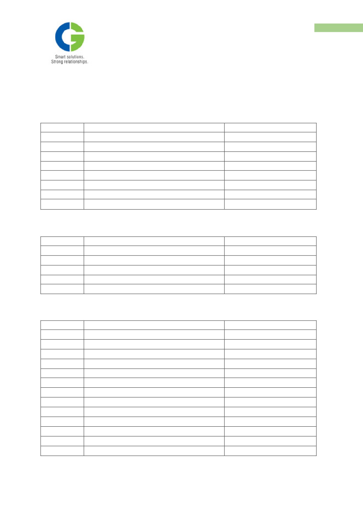
A. Power Pack and accessories
S. No.
Description
Drawing No.
1
Power Pack Arrangement
45812450
2
Power pack Assembly
45812440
3
Air Cleaner Arrangement
45831110 S1,S2
4
Exhaust Pipe Mounting Arrangement
45820420
5
Radiator Mounting Arrangement
45820470
6
Radiator Water Piping Arrangement
45820510 S1,S2
7
Schematic Diagram of Hydraulic Circuit
45825260
8
Fuel Line Piping Arrangement
45825270
B. Wiring Schematics
S. No.
Description
Drawing No.
1
Power Schematic
30104007
2
Control Schematic Cab - 1
30104005
3
Control Schematic Cab - 2
30104006
4
Auxiliary Schematic
30104008
5
Power pack schematic 1 & 2
30104009
C. General Arrangement Drawings
S. No.
Description
Drawing No.
1
Traction Alternator
CGA/101004
2
Traction Motor
11290003
3
Power Rectifier - OGA
1216-02-1807
4
Power Rectifier - IGA
1216-03-1807
5
Auxiliary Alternator
19A 3086
6
Rectifier Regulator Unit
4A 3089
7
Driver’s Desk
31610140
8
Control Cubicle Cab 1 - OGA
31610142
9
Control Cubicle Cab 1 - IGA
31610143
10
Control Cubicle Cab 2
31610138
11
Motor Switch Group Cubicle - OGA
31610144
12
Motor Switch Group Cubicle - IGA
31610145
13
Resistor Panel
31610139
CARDAN SHAFT
Annexure 1
Cardan Shaft
A1.1 Introduction
1. Exploded view
2. Specifications
3. Installation, Maintenance and servicing
MAINTENANCE MANUAL FOR DETC-US
CARDAN SHAFT
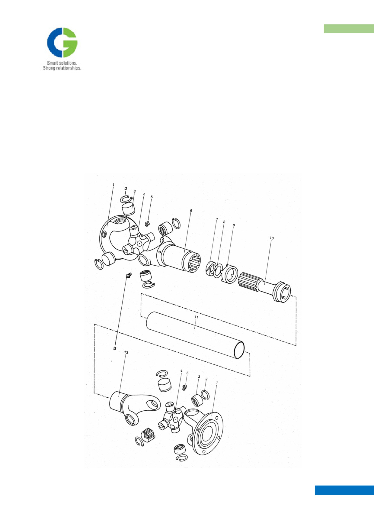
A1.2 Key to typical exploded view:
1. Flange yoke
2. snap ring
3. Bearing cups
U.J. kit
4. Journal
5. Lubricator
6. Sleeve yoke with sleeve yoke plug
7. Cork washer
8. Steel washer
9. Dust cap
10. Slip stub shaft
11. Tube
12. Stud ball yoke
13. Lubricator
A1.3 Installation, Maintenance and Servicing
A1.3.1 Transport and storage
Care should be taken on the following points:
1. The shafts should be transported in horizontal position. For vertical transportation an
additional protection must be provided in order to avoid the shaft coming apart. The sleeve
yoke plug and the dust cap of the spline seal must not be loaded by the weight of the
propeller shaft.
2. Shocks and bumps must be avoided during transport.
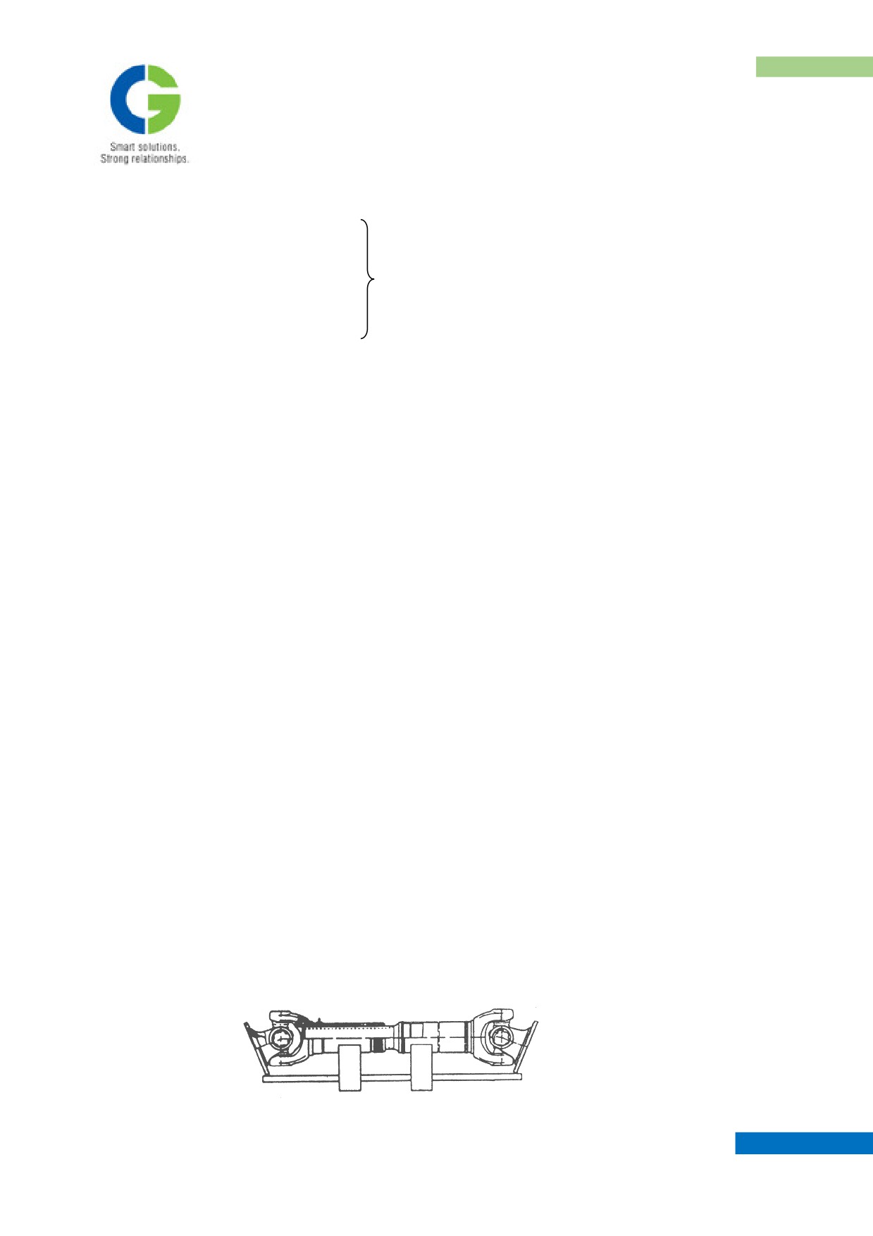
3. The shafts should be stored side by side on wooden frames and the flange yokes should be
supported loosely, as shown
MAINTENANCE MANUAL FOR DETC-US
CARDAN SHAFT
4. Balance weight strips wherever fitted on the shaft tube should not be removed. Removal will
create unbalance which will cause uneven running and premature wear of the propeller shaft
joints and the bearings of the connected units.
A1.3.2 Installation
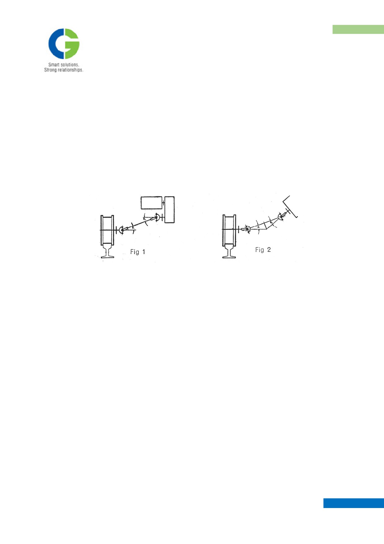
For satisfactory operation, the driving shaft and the driven shaft should be coplanar and the
propeller shaft should be installed either as per arrangement 1 or 2 shown below:
The flanges of the propeller shaft and that of companion flange (propeller shaft mating part
fitted on the driving/driven shaft) should be free of dirt, grease, paint, anti-rust compound, burrs,
etc., This is important as torque is transmitted through friction between flanges. For the same
reason only the bolts and nuts recommended, same to be torque tightened.
The spigot bore/dia of companion flange should be concentric with driving/driven shaft on
which it is fitted and its flange face should be square to driving/driven shaft to ensure true
running of propeller shaft.
The mounting bold should be steadily tightened with a torque wrench in a crosswise pattern to
torque values indicated.
While using fixed length propeller shaft and universal joint (types J & L) at least one of the
units to be connected should be capable of axial movement and subsequent bolting down as the
propeller shaft/universal joint has to be fitted over the flange spigot dia/bore.
MAINTENANCE MANUAL FOR DETC-US
CARDAN SHAFT
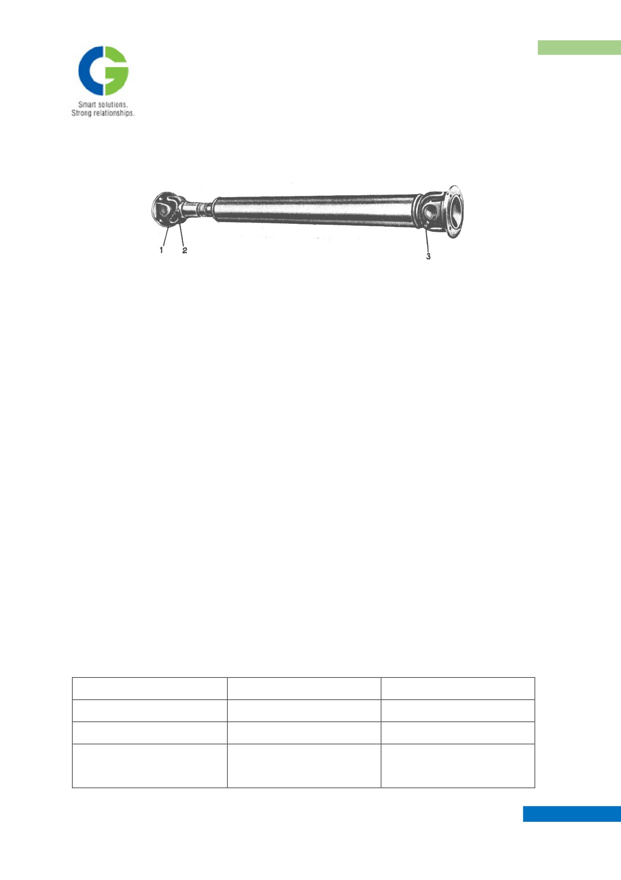
Important: The propeller shaft/universal joint is to be is to be greased at points 1,2 and 3 before
installation.
A1.3.3 Maintenance
Maintenance should be carried out at regular intervals and it is advisable to do-ordinate this with
the maintenance work of the other items of machinery/installation. The maintenance intervals
mentioned herein are only for guidance. The actual frequency will depend on working
conditions.
1. Noise testing: continuously, any deviation from normal working noise should be located
and corrected immediately.
2. Checking of Flange bolts: periodically the bolts should be checked for tightness and
tightened whenever necessary.
3. Lubrication: propeller shafts should be periodically greased with lithium based grease only.
This should be acid and soap free, as the former causes corrosion and the latter clogs the
passages. Recommended grease are given in separate table. The propeller shaft should be
greased at three points, where the grease nipples are provided. Greasing of joints to be done
till the grease comes out through the seals, and for sleeve yoke till the grease flows out
through the vent holes on the sleeve yoke plug.
Joints
Sliding splines
Application
Earth moving equipment
5000 kms
2500 kms
Trucks, Lorries, Busses
10000 kms
5000 kms
Locomotives,
Railcars,
30 days/500 hrs.
30 days/500 hrs.
Rolling
mills
Cranes,
MAINTENANCE MANUAL FOR DETC-US
CARDAN SHAFT
Marine applications &
general machinery
A1.3.4 Servicing
A1.3.4.1 Dis-assembly of propeller shaft
Remove the dust cap, pull back the cork washer & steel washer and pull off the sliding joint
from the shaft. (Flange yoke to sleeve yoke)
Disassembly of the universal joint
(Snap ring type : 0400 to 1510 series)
1. Clean enamel / paint from snap rings and top of bearing cups. Remove snap rings by pinching
their ears together with a pair of pliers and rising with a screw driver. If ring does not snap out of
the groove readily, tap end of bearing race lightly to relieve the pressure against the ring. Support
sleeve yoke lug on a wooden block and tap yoke ears with a soft hammer.
1. Now the bearing cup should begin to emerge. Turn the joint and finally remove the bearing
cup with fingers. Care should be taken to avoid any of needle rollers being dropped.
2. Similarly remove the opposite bearing cup also. If necessary tap bearing cup from inside
with a small dia bar, taking care not to damage the bearing cups / journal.
3. Now the sleeve yoke can be removed, rest the two exposed trunnions on wooden blocks to
avoid damage. By tapping the yoke ears lightly with a soft hammer and following the above
procedure, remove the other two bearing cups.
4. On the same lines dis-assemble the fixed joint (stub ball yoke side) also.
A1.3.4.1.1 Examination and check for wear
The parts most likely to show signs of wear after long usage are bearing cups and journals. Should
looseness in the fit of these parts, load markings or distortion be observed they should be renewed
complete as a unit, because worn needle bearings used with a new journal, or new needle bearings
used with a worn journal, will wear more rapidly, making another replacement necessary in a short
time.
MAINTENANCE MANUAL FOR DETC-US
CARDAN SHAFT
It is essential that bearing cups are a light drive fit in the yoke trunion
In the rare event of wear having taken place in the yoke cross holes, the holes will most certainly be
oval and the yokes must be replaced.
In the case of wear of the cross holes in stub ball yoke, which is welded onto tube, only in cases of
emergency should this stub ball yoke be replaced. Normally stub ball yoke along with tube and slip
stub shaft should be replaced as one unit.
The other parts likely to show signs of wear are the splined sleeve yoke, or slip stub shaft. a total of
0.004” (0.1mm) circumferential movement, measure on the outside diameter of the spline, should
not be exceeded. Should the slip stub shaft require renewing, this must be dealt with in the same
way as the stub ball yoke.
A1.3.4.2 Re-assembly
1.
Assemble needle rollers in the bearing cups. Should any difficulty be encountered while
assembling needle rollers in the bearing cup, smear the wall of the cup with grease. It is
advisable to install new gaskets and gasket retainers on the journal or spider assembly. It is
also useful to have snap rings available as replacements in the even of damaging a ring
whilst dis-assembling the joint.
2.
See that all drilled holes in journals are cleaned out and filled with grease, with the rollers in
position fill the races about one-third full with grease.
3.
Insert journal in yoke holes and using a soft round drift with flat face about 1/32” (0.8mm)
smaller in diameter than the hole in the yoke, tap the bearing cup into position. Repeat this
operation for the other three bearing cups. Fit snap rings or bearing caps, bearing cap
screws, locking plate etc., with the bearing cap type make sure that bearing cups are placed
with the slot in the top of the cup in line with bearing cap screw holes, so that they are
prevented from rotating by the key in the bearing cap. If joint appears to bind, tap lightly
with a wooden mallet, which will relieve any pressure of the bearings on the end of the
journal. When refitting a sliding joint on shaft, be sure that trunnions in sliding and fixed
yoke are in line. Observing that arrows marked on splined sleeve yoke and slip stub/tube are
in line can check this.
MAINTENANCE MANUAL FOR DETC-US

CARDAN SHAFT
Annexure 2
Trouble shooting - Power pack
Sl. No.
IN CASE OF
CAUSE
REMEDY
Drained battery
Check & charge battery
Engine does
1
not crank
Check the battery connections
Incorrect /loosen battery connections
and rectify
No fuel in tank
Add sufficient fuel
Fuel filter clogged
Clean the fuel filter
Engine cranks
2
but doesn’t
Identify any loose connections
Improper Fuel connections at pump
starts
and rectify
Restriction in air inlet / exhaust
Check piping and rectify if any
restriction exists
Air entering in the fuel system
Check all the fuel connections,
tighten if found loose
Starts but does
3
Fuel suction line restricted
Inspect fuel line for any blockage
not throttle
Inspect fuel sample / verify by
Fuel contaminated
connecting a temporary fuel tank
Remove and clean the filter
Air inlet filter clogged
element
Excessive
4
exhaust smoke
Contaminated fuel
Check the fuel sample &
replenish with new fuel
Restriction in air inlet / exhaust
Check piping and rectify if any
restriction exists
Low engine
5
out put power
Check the lube oil level in sump
Excessive lubricating oil
with dipstick provided and reduce
if it is high
MAINTENANCE MANUAL FOR DETC-US

CARDAN SHAFT
Improper / leakage in fuel flow to fuel
Check any leakage / restriction at
pump
connections, rectify if any
Malfunction of throttle solenoid valves
Check and rectify if any
Malfunction of tachometer
Test and rectify
Low engine
Fuel line restricted
Check and rectify
6
speed at full
throttle
Excessive traction load on the power
Reduce the vehicle load
pack
Release the brake on desk and
Vehicle brakes applied
bring brake handle to ‘Release &
running’
Vehicle does
Check & select master controller
not moves
Controls not engaged in Forward /
7
direction selector to required
when engine
Reverse
position, if not selected
throttled
Release the parking brake with
Parking brakes applied
operating switch provided on
desk
Check and open the isolating cock
at air inlet side and Check for
System Pressure not developed
proper functioning of Limiting
valve and non return valve
Check water availability at pipe
No water
Insufficient suction head / inlet restricted
outlet / inspect for any block in
outlet from
the pipe
8
water rising
apparatus
Isolating valve at outlet is closed
Check and open the valve
Check for proper connections /
Hose / pipe joints leaking or disconnected
routing with respect to drawing
MAINTENANCE MANUAL FOR DETC-US
TIGHTENING TORQUE
Annexure 3
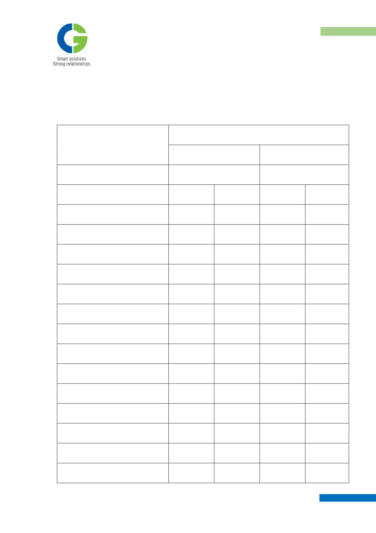
TIGHTENING TORQUE IN N-m FOR THREADED COMPONENTS.
MATERIAL PROPERTY CLASS AS PER IS:1367
8.8
10.9
MIN.YIELDSTRESS N/mm2
640
900
SIZE
SCREW
BOLT
SCREW
BOLT
M4
2.5
1.5
3
2
M5
6
3
8
4
M6
10
7
15
11
M8
24
18
34
26
M8x1.0
29
23
41
32
M10
46
38
64
53
M10X1.0
53
41
75
57
M12
76
63
107
89
M12X1.5
93
70
130
99
M14
117
90
165
126
M14X1.5
137
121
193
170
M16
176
139
248
195
M16X1.5
196
156
275
220
M18
245
186
344
261
MAINTENANCE MANUAL FOR DETC-US
TIGHTENING TORQUE
M18X1.5
264
220
372
310
M20
328
264
461
372
M20X1.5
343
294
482
413
M20X2.0
333
284
468
399
M22
421
343
592
482
M22X1.5
441
392
620
551
M22X2.0
431
362
606
510
M24
549
411
772
579
M24X1.5
578
441
813
620
M24X2.0
568
431
799
606
M27
921
539
1296
758
M27X1.5
1078
637
1516
896
M27X2.0
1029
607
1447
854
M30
1264
725
1778
1020
M30X1.5
1539
921
2164
1296
M30X2.0
1470
882
2068
1241
M33
1735
2440
M33X1.5
2059
2895
M33X2.0
1980
2785
M36
2216
3116
MAINTENANCE MANUAL FOR DETC-US
TIGHTENING TORQUE
M36X1.5
2706
3805
M36X2.0
2608
3668
M36X3.0
2402
3378
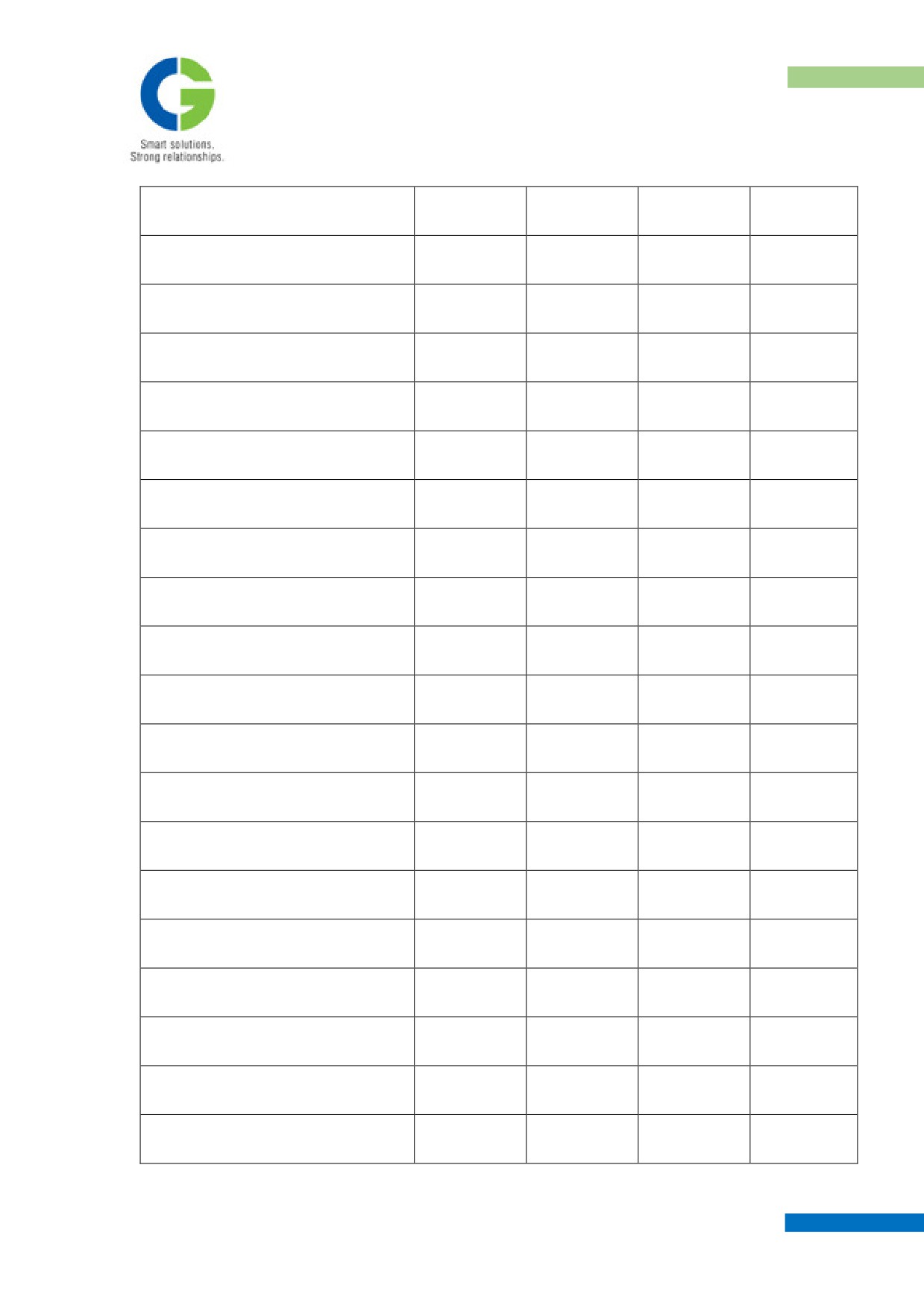
The above values apply to bolts of lengths in excess of 5 times the thread diameter. For
smaller lengths the valves are to be reduced by 10%.
To get lb-ft multiply the above values by 0.737
To get lb-inch multiply the above values by 8.85
To get kg-m multiply the above values by 0.102
MAINTENANCE MANUAL FOR DETC-US