DYNAPAC Paver finisher F 121 C, F 141 C Type 635. Operation & Maintenance (Order number: 4812026925) - page 6
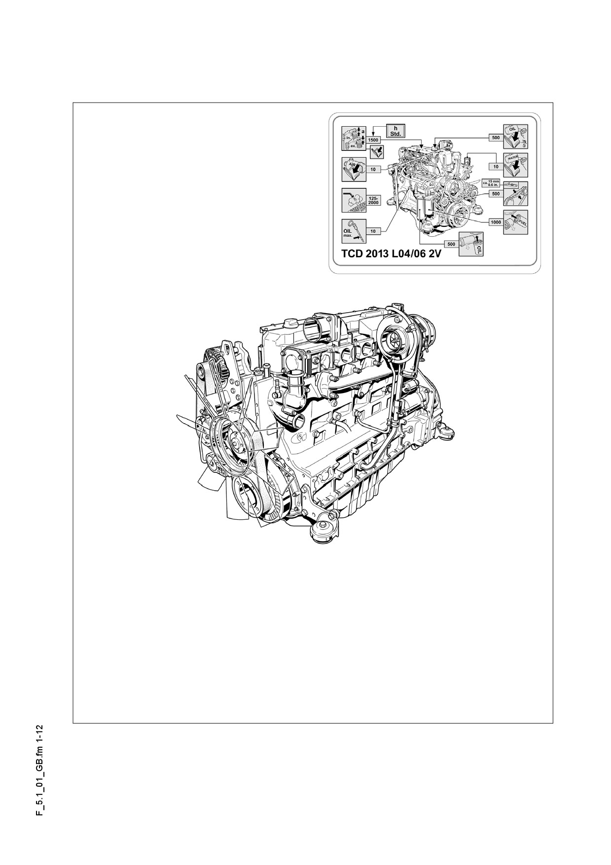
F 5.1
Maintenance - Engine
1
Maintenance - engine sub-unit
m In addition to these Maintenance Instructions, the Maintenance Instructions of the en-
gine manufacturer must always also be observed. All other maintenance work and in-
tervals noted in these instructions are also binding.
F 5.1 1
1.1
Maintenance intervals
Interval
Points of maintenance
Remark
-
Fuel tank
q
Check the filling level
-
Fuel tank
1
q
Refill with fuel
-
Fuel tank
q
Clean the tank and device
-
Engine lube-oil system
q
oil level check
-
Engine lube-oil system
q
topping up the oil
2
-
Engine lube-oil system
q
oil change
-
Engine lube-oil system
q
oil filter change
-
Engine fuel system
q
Fuel filter (drain the water separa-
tor)
-
Engine fuel system
q
replacement of the fuel pre-filter
3
-
Engine fuel system
q
replacement of the fuel filter
-
Engine fuel system
q
bleeding of fuel system
Maintenance
q
Maintenance during run-in period
g
F 5.1 2
Interval
Points of maintenance
Remark
-
Engine air filter
q
checking of air filter
-
Engine air filter
q
4
dust collecting bin emptying
-
Engine air filter
q
q
Clean / Replace the filter car-
tridge
-
Cooling system of the engine
q
Inspection of radiator fins
-
Cooling system of the engine
q
Cleaning of the radiator fins
-
Cooling system of the engine
q
Check the level of the coolant.
5
-
Cooling system of the engine
q
topping up the coolant
-
Cooling system of the engine
q
changing the coolant
-
Cooling system of the engine
q
Inspection of coolant
(additive concentration)
-
Engine drive belt
q
q
checking of drive belt
6
-
Engine drive belt
q
tightening of drive belt
-
Engine exhaust system
q
(o)
checking of particle filter
7
-
Engine exhaust system
g
q
q
(o)
cleaning of particle filter
Maintenance
q
Maintenance during run-in period
g
F 5.1 3
1.2
Points of maintenance
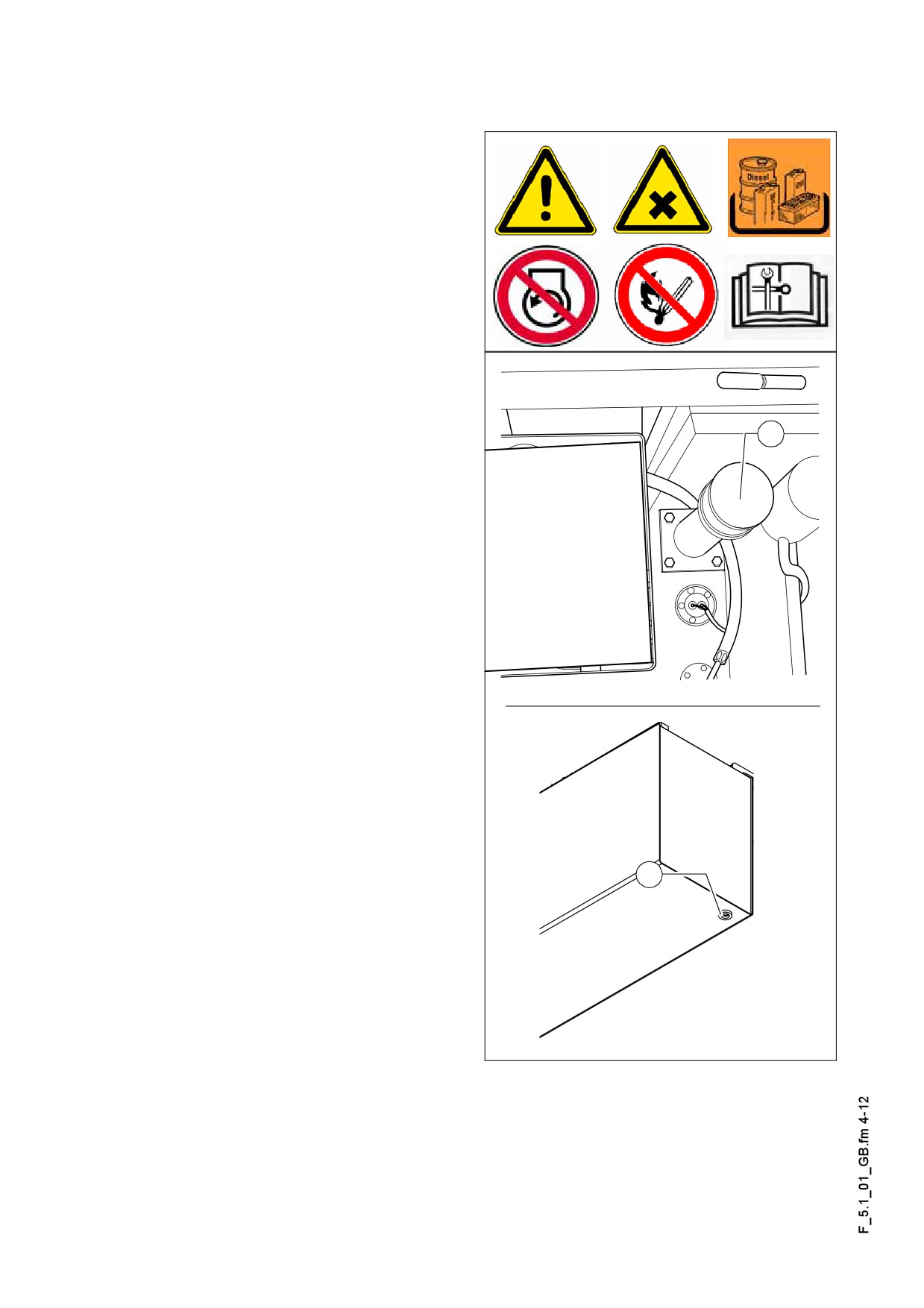
Engine fuel tank (1)
- Check the filling level on the gauge
on the operating panel.
A Fill the fuel tank before each start of
work so that the fuel system cannot „run
dry“ and this way the time consuming
venting (bleeding) can be avoided.
For filling in the fuel:
- Unscrew cap (A) (under the tank cov-
er).
A
- Fill in fuel through the filling port until
the required filling is achieved.
- Replace the cap (A).
Cleaning of tank and device:
- Unscrew the plug (B) at the bottom of
the tank and drain into a collection pan
about 1 lit fuel.
- After drainage screw back the plug
with a new seal ring.
B
Dieseltank.eps/HDieseltank_bot.bmp
F 5.1 4
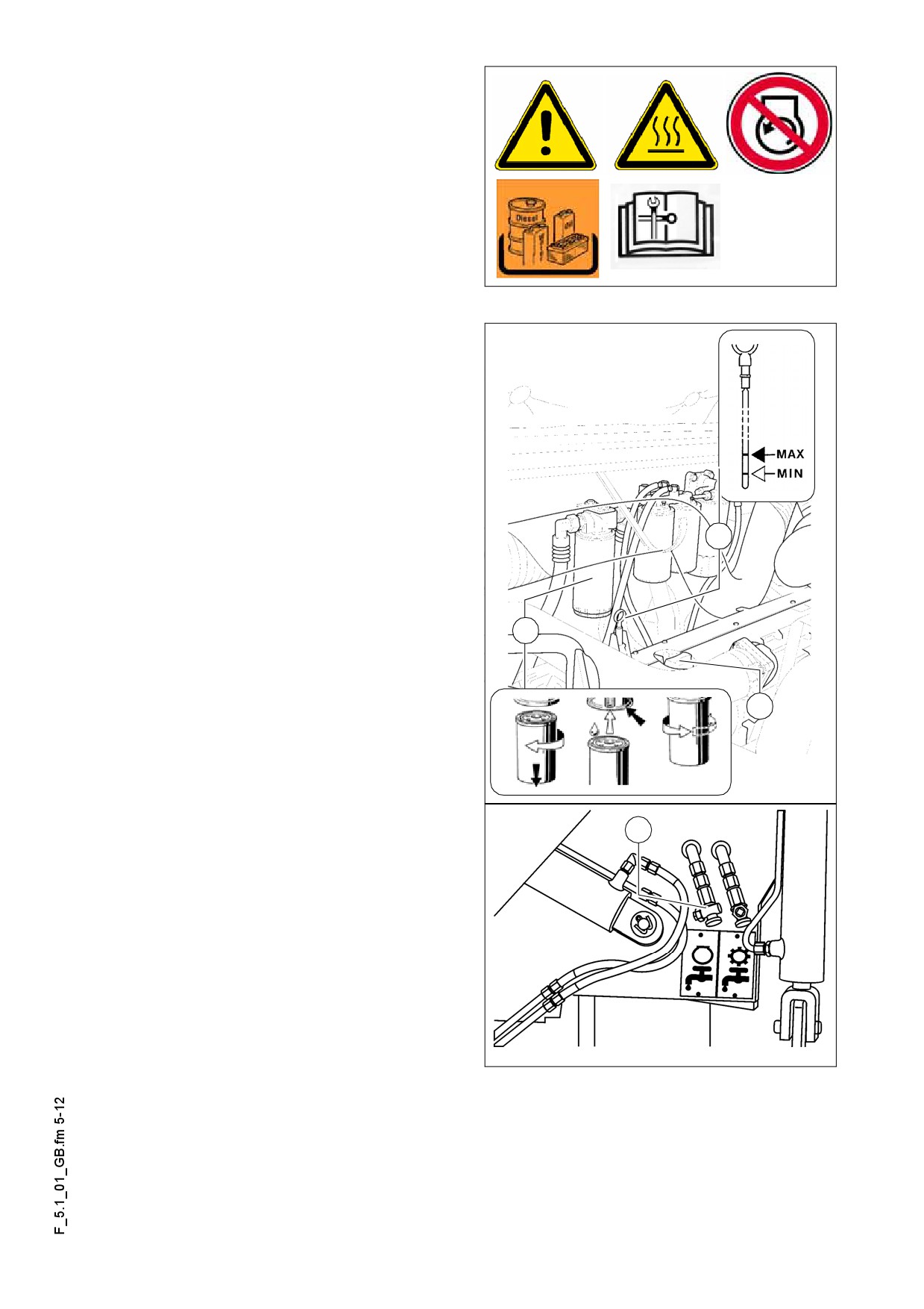
Engine lube-oil system (2)
Checking the oil level
In case of correct oil level, the oil is be-
A
tween the two notches of the dipstick
(A).
Check the oil level with a paver finisher
A
standing on a flat area!
If there is too much oil in the engine, the
m
gaskets and seals may get damaged,
while too little oil can lead to the over-
heating of the oil and the damage of the
engine.
For filling in the oil:
- Remove cap (B).
- Fill in oil until the correct level is
A
achieved.
- Return cap (B).
- Check the oil level once again using
the dipstick.
D
Oil change:
B
Change the oil when the engine is at op-
A
erating temperature.
- Remove the cover cap of the oil drain
port (C) and screw on the hose provid-
C
ed as an accessory.
- Place the end of the hose in a dish to
catch the oil.
- Open the shutoff valve with a spanner
and let the oil fully drain.
- Shut off the valve, remove the hose
and return the cover cap.
- Fill in the oil of specified quality
through the filling port on the engine
F0112_A1.bmp
until the oil level rises to the correct
mark of the dipstick (A).
F 5.1 5
Changing the oil filter:
A As part of the oil change mount the new filter after the used oil was drained.
- Untighten the filter (D) and clean its resting surface.
- Apply thin coat of oil to the seal of the new filter and fill the filter with oil before
mounting.
- Tighten the filter by hand.
A After mounting the oil filter check the oil pressure gauge and the proper tightness dur-
ing the trial operation. Check the oil level once again.
F 5.1 6
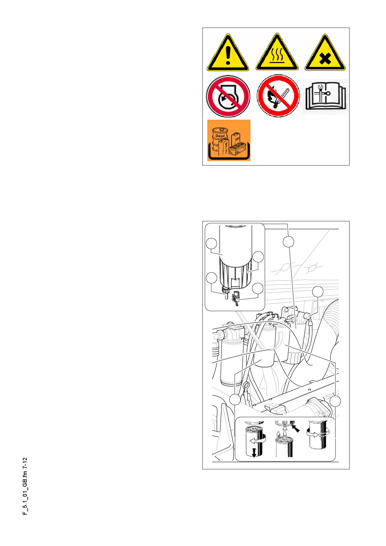
Engine fuel system (3)
A The fuel filter system consists of three fil-
ters:
- Pre-filter (A) with water separator
- Two main filters (B)
A Depending on the machine, the pre-filter
is in the engine compartment or under
the tank lid!
Pre-filter - draining of water
A Empty the collection bin by the specified
intervals or when the engine electronic
indicates a fault.
- Drain the separated water at the tap (C), collect it, and close the tap again.
Change of pre-filter:
- Drain the separated water at the tap
A
A
(C), collect it, and close the tap again.
E
- Pull down the connection of the water
detector (D)
C
- Untighten the filter cartridge (A) with
D
the collection sump using a pair of oil
F
filter tongs or oil filter strap and un-
screw
it.
- Unscrew the collection sump (E) from
the filter cartridge and clean as re-
quired.
- Clean
the sealing surface of the filter
holder.
- Apply a thin coat of oil to the gasket of
the collection sump, drive it under the
filter cartridge and tighten by hand.
- Apply a thin coat of oil to the gasket of
B
B
the filter cartridges, drive them under
the holder and tighten by hand.
- Replace the connection of the water
detector (D)
F 5.1 7
Replacement of the main filter:
- Untighten the filter (B) and clean its resting surface.
- Apply a thin coat of oil to the gasket of the new filter.
- Tighten the filter by hand.
A After mounting the filter check for proper tightness during the trial run.
Venting the filter:
- Release the bayonet-mount of the manual fuel pump (F) by pressing and twisting
counter-clockwise at the same time.
- The pump piston now can be displaced by a spring.
- Until strong resistance is felt and the pump moves already very slowly.
- Keep on pumping a few times. (Fill the return pipelines).
- Start the engine and run it for about 5 minutes at idling speed or under a slight load.
- Check the tightness of the pre-filter in the meantime.
- Close the bayonet-mount of the manual fuel pump (F) by pressing and twisting
clockwise at the same time.
F 5.1 8
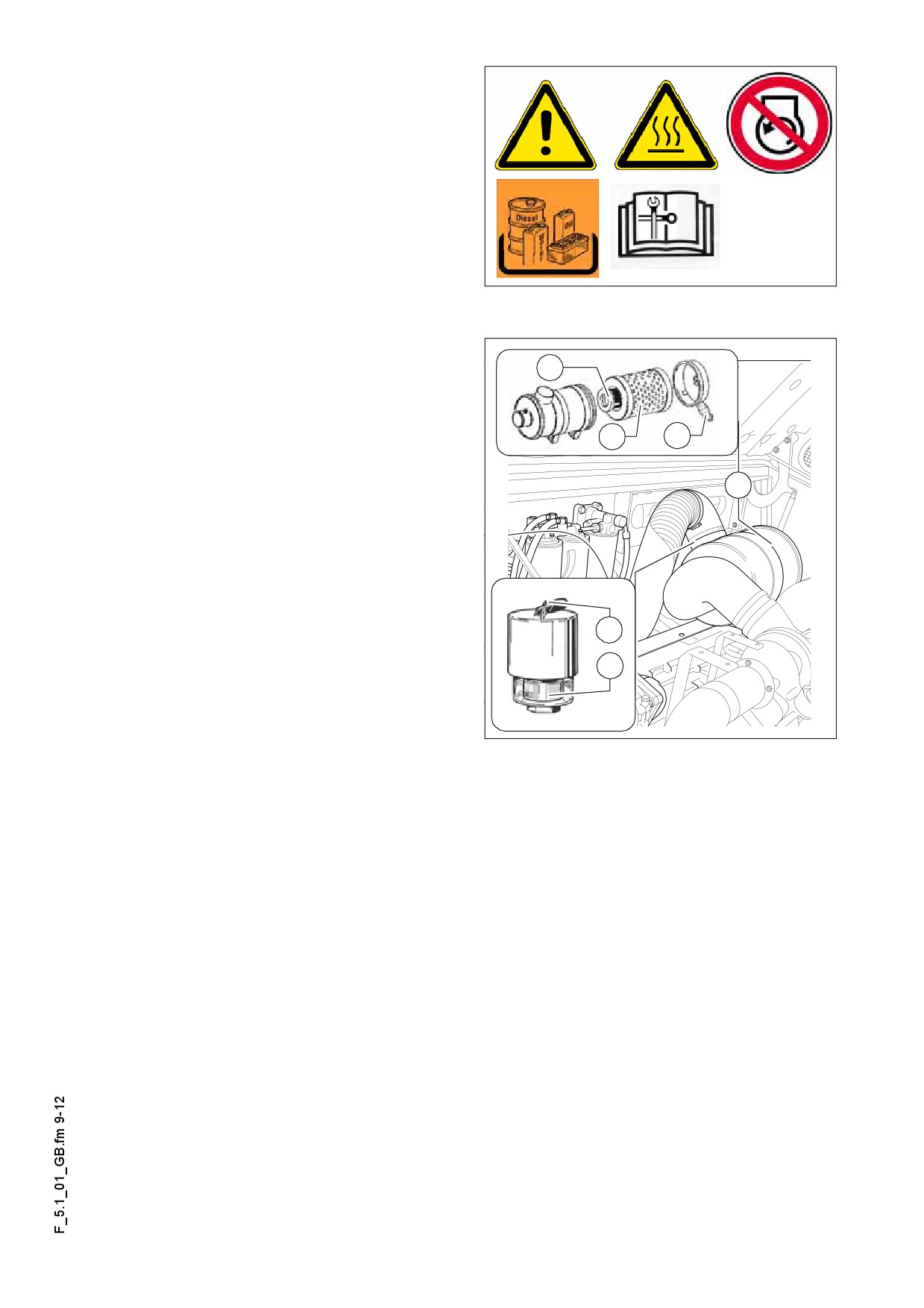
Engine air filter (4)
Emptying the dust collection bin
- Empty the dust collection valve (B) on
the air cleaner housing (A) by pressing
the discharge port in the direction of
the arrow.
- Discharge the eventually compacted
dust by pressing together the upper
part of the valve.
Clean the discharge port from time to
A
time.
D
Cleaning / replacement of the air filter
C
B
cartridge
Pollution
of the filter of the combustion
A
A
air depends on the dust content of the air
and the mesh size of the filter selected.
The maintenance of the filter becomes
A
necessary if:
E
- The maintenance indicator
(O) red
servicing field (C) is fully visible when
C
the engine is stopped.
- When the engine electronic unit indi-
cates service need
- Open the air filter lid.
- Withdraw the filter cartridge (C) and the safety cartridge (D)
A Clean the filter cartridge (C) and replace min. after one year.
- Blow out with dry pressure air (max. 5 bar) from inside out or tap it (in case of emer-
gency only).
A The cartridges should not get damaged in the process.
- Check the soundness of the filter papers of the filter cartridge (by exposing to light)
and the soundness of the seals. Replace them as required.
A Replace the safety cartridge (D) after 5 filter maintenance, but min. after 2 years (nev-
er clean it!).
After completing the maintenance works:
- Press the reset button (E) of the maintenance indicator (O). The maintenance indi-
cator is ready for operation once again.
F 5.1 9
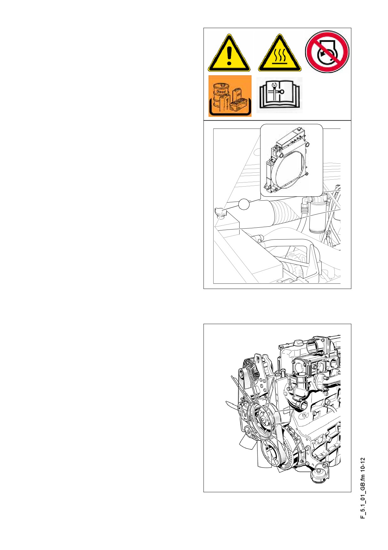
Coolant system of the engine (5)
Checking / topping up of coolant
The coolant level is checked when the
engine is cold. Make sure that the anti-
freeze and anti-corrosive liquid us suffi-
cient (-25 °C).
When hot, the system is under pressure.
f
When opening, there is a danger of
scalding!
- If necessary fill in sufficient amount of
coolant through the open port (A) of
the compensating tank.
Changing the coolant
A
See operating instructions for the engine
A
Checking and cleaning of the radiator
fins
- If necessary, remove leaves, dust or
sand from the radiator.
Engine drive belt (6)
Checking of drive belt/replacement
A See operating instructions for the engine
F 5.1 10
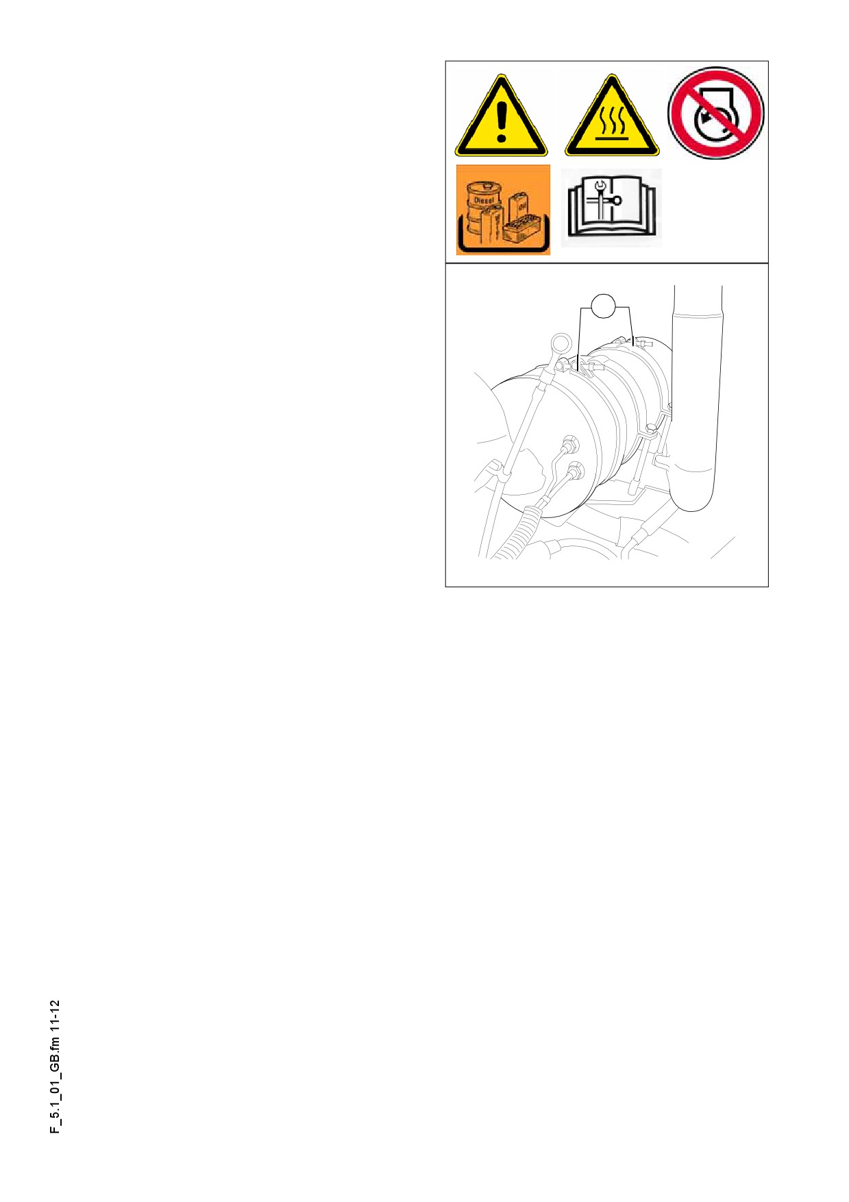
Engine exhaust system (7)
Cleaning of particle filter
As considerable amount of soot is accu-
m
mulated in the filter, the cleaning must
be performed under appropriate exhaust
system.
Clean the filter element removed with
m
oil-free and grease-free pressure air!
a
- Marking the flow of direction of the ex-
haust gas on the filter case.
- Remove the filter element by untight-
ening the two clips (a).
- First blow out the inlet side.
The pressure of the compressed air can
m
be max. 5 bars and the nozzle shall not
be closer to the filter edge than 10 cm.
- Carefully blow out all the filter passag-
es.
Partikelfilter.eps
- Turn around the filter element, and re-
peat the process on the other side as
well.
- Repeat the process until no more carbon residue leaves the filter.
- Replace the filter element, taking care of the proper direction of flow.
After cleaning for a short while more soot discharge is expected during operation.
A
- In case of sticky, oily soot the filter must be heated to about 450°C and the cleaning
shall be carried out preferably with the hot filter.
The filter shall not be cleaned with water/steam or detergent in any case!
m
The carbon particles are harmful to your health! In case of filter change or cleaning,
f
wear appropriate protection gear!
F 5.1 11
F 6.0
Maintenance - Hydraulic system
1
Maintenance - hydraulic system
F 6.0 1
1.1
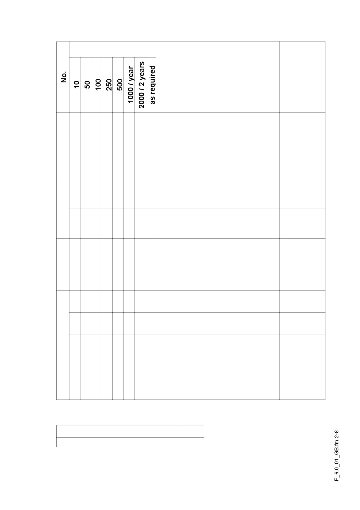
Maintenance intervals
Interval
Points of maintenance
Remark
-
Hydraulic oil tank
q
Check the filling level
-
Hydraulic oil tank
1
q
Top up with oil
-
Hydraulic oil tank
q
oil change and cleaning
-
Hydraulic oil tank
q
Checking of maintenance indica-
tor
2
-
Hydraulic oil tank
q
q
Intake / return
change of hydraulic filter, venting
-
High pressure filter
q
Checking of maintenance indica-
tor
3
-
High pressure filter
q
replacement of filter cartridge
-
Pump distribution gear
q
oil level check
-
Pump distribution gear
4
q
topping up the oil
-
Pump distribution gear
q
oil change
-
Hydraulic hoses
q
observation
5
-
Hydraulic hoses
q
q
Replace the hoses
Maintenance
q
Maintenance during run-in period
g
F 6.0 2
1.2
Points of maintenance
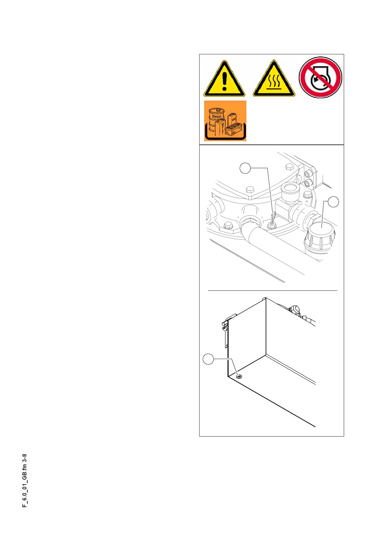
Hydraulic oil tank (1)
- Oil level check on dipstick (A).
In case of retracted cylinders the oil level
A
shall be at the upper mark.
For filling in the oil:
- Remove cap (B).
- Fill in oil through the filling port until the
required filling level is achieved on the
dipstick (A).
A
- Return cap (B).
Regularly clean the vent port of the oil
A
tank from dust and pollution. Clean the
B
surfaces of the oil cooler.
Use only the recommended hydraulic
m
oils
- see section „Recommended hy-
draulic oils“.
For changing the oil:
- To drain the hydraulic oil unscrew the
drain plug (C) at the bottom of the
tank.
- Collect the oil in a bin using a funnel.
- After drainage screw back the plug
with a new seal ring.
Change the oil when the engine is at op-
A
erating temperature.
C
When changing the hydraulic oil also
m
change the filter.
Hytank_dip.wmf/Hydtank_bot.bmp
F 6.0 3
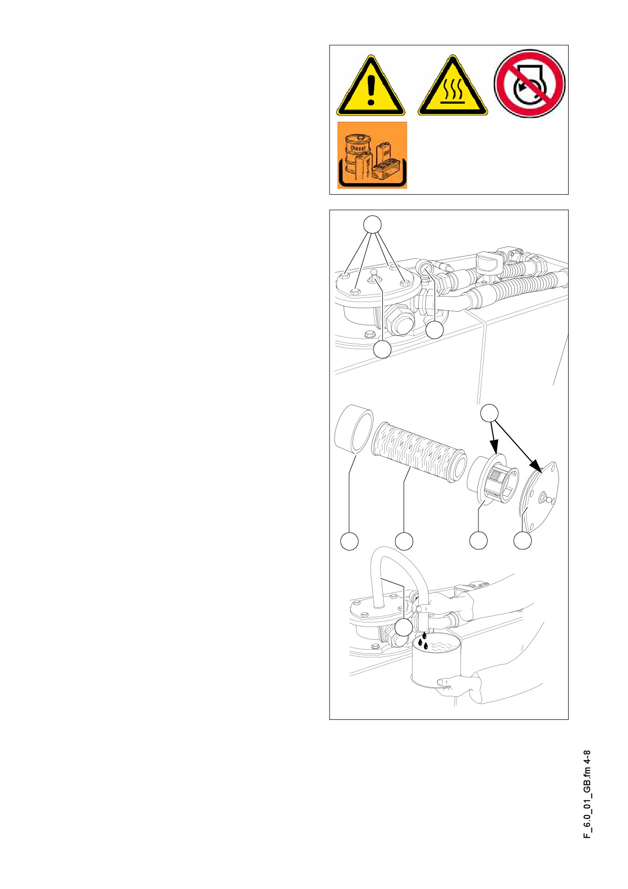
Suction/return flow hydraulic filter (2)
Change the filter by the intervals speci-
fied or when the maintenance indicator
(A) at a hydraulic oil temperature of 80°C
comes to the red mark.
The temperature of the hydraulic oil can
A
be read on the hydraulic temperature in-
dicator (O) at the operating position.
When changing the hydraulic oil also
m
B
change the filter.
- Remove the lid fastening screws (B)
and remove the lid.
- Disassemble the withdrawn unit into
the following parts:
- lid (C)
A
- separating plate (D)
H
- filter (E)
- dirt collection cage (F)
- Clean the filter case, the lid, the sepa-
rating plate and the dirt collection
G
cage.
- Check and replace the O-rings (G)
when required.
- Wet the seal surfaces and the O-ring
with clean fuel.
F
E
D
C
I
Hydtank_V2.eps/Montage2.eps/Hydtank_V2a.eps
F 6.0 4
Venting the filter:
- Fill the open filter case with hydraulic oil to about 2 cm below the upper rim.
- Should the oil level drop, top up with oil.
A The slow sinking of the oil level by about 1 cm/min is normal!
- When the oil level remains steady, mount the assembled unit with the new filter car-
tridge, carefully into the housing and tighten the locking screws of the lid (B).
- Open the vent screw (H).
- Mount a transparent hose (l) on the vent screw and lead it into an appropriate con-
tainer.
- Start the traction engine at idling speed.
- Shut-off the bleeding screw (H) as soon as the oil discharged through the hose is
clean and free of bubbles of air.
A The process from the mounting of the filter lid until starting the engine shall take place
within 3 min or else the oil level drops too much in the filter case.
m Check the seal after changing the filter.
F 6.0 5
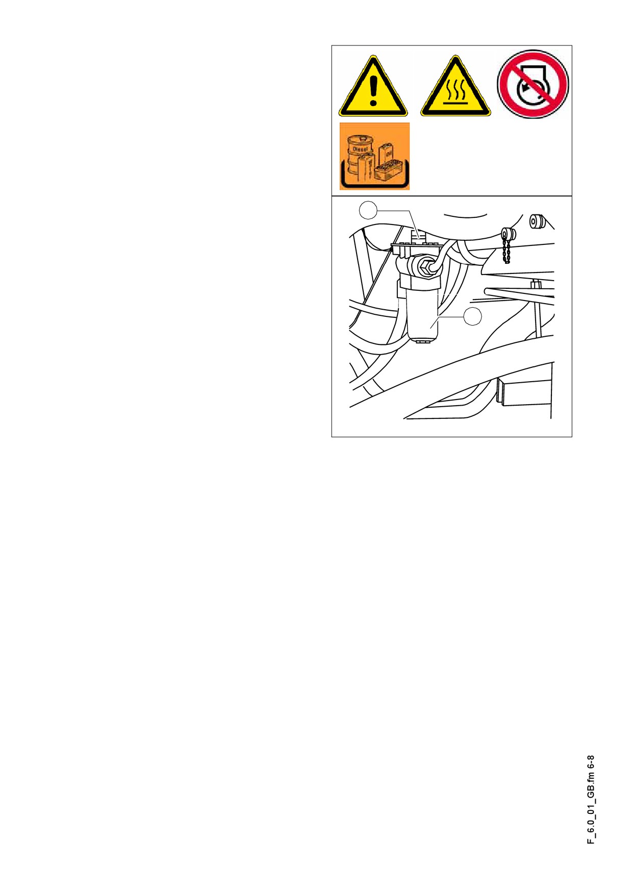
High pressure filter (3)
Replace the filter cartridge when the
maintenance indicator (A) turns red.
- Unscrew filter house (B).
- Remove the filter cartridge
- Clean the filter house.
- Insert the new filter cartidge.
A
- Replace the seal ring of the filter hous-
ing.
- Turn on the filter housing by hand and
tighten it using a wrench.
- Start the trial operation and check the
tightness of the filter.
B
A Replace the seal ring whenever the filter
cartridge is replaced.
A After the replacement of the filter car-
tridge the red signal of the maintenance
indicator
(A) automatically reverts to
green.
Hochdr.bmp
F 6.0 6
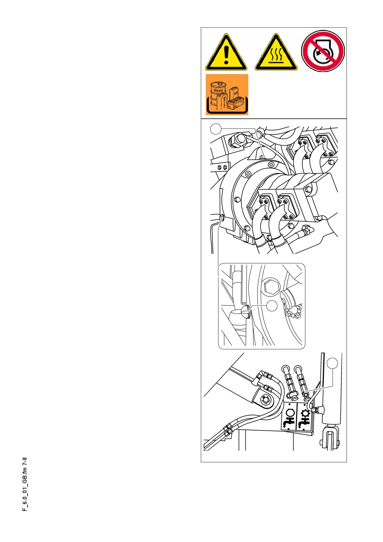
Pump distribution gear (4)
- Oil level checking on the viewing
glass (A) (at the side of the distribution
box).
A The oil level must be up to the center of
the viewing glass.
For filling in the oil:
B
- Unscrew the filling in screw plug (B).
- Fill in oil through the filling port until the
required filling level is achieved on the
viewing glass (A).
- Return filling screw plug (B).
Take care of cleanliness!
m
Oil change:
Change the oil when the engine is at op-
erating temperature.
- Remove the cover cap of the oil drain
port (C) and screw on the hose provid-
ed as an accessory.
- Place the end of the hose in a dish to
catch the oil.
A
- Open the shutoff valve with a spanner
and let the oil fully drain.
- Shut off the valve, remove the hose
and return the cover cap.
- Fill in the oil of specified quality
through the filling port on the distribu-
C
tion box (B) until the oil level rises to
the center of the viewing glass (A).
PVG2.wmf/PVG_Glas.wmf/F0112_A1.bmp
F 6.0 7
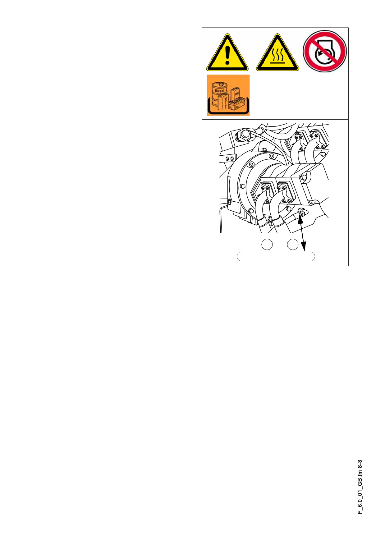
Hydraulic hoses (5)
- Check the condition of the hydraulic
hoses specifically.
- Immediately replace the injured hos-
es.
f The aged hoses may become porous
and burst! Risk of accident!
A The numbers stamped in the joints of the
hoses state the date of manufacture (A)
and the maximum pressure (B) allowed
for that hose.
m Do not fit hoses, which were in storage
for a long time and check the permitted
pressure rating.
A
B
DHH 09/00 225BAR
PVG2.wmf
F 6.0 8
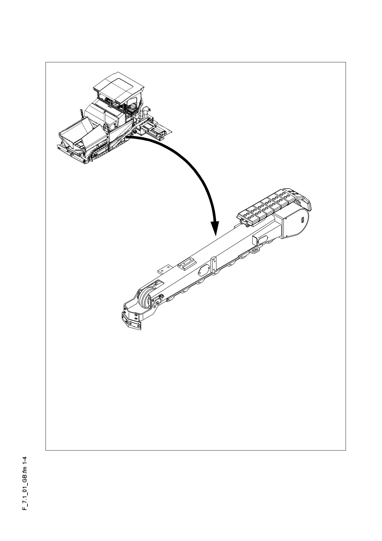
F 7.1
Maintenance - running gear
1
Maintenance - running gear
635_ISO_Dyn.bmp/LW_DYN_inter.bmp
F 7.1 1
1.1
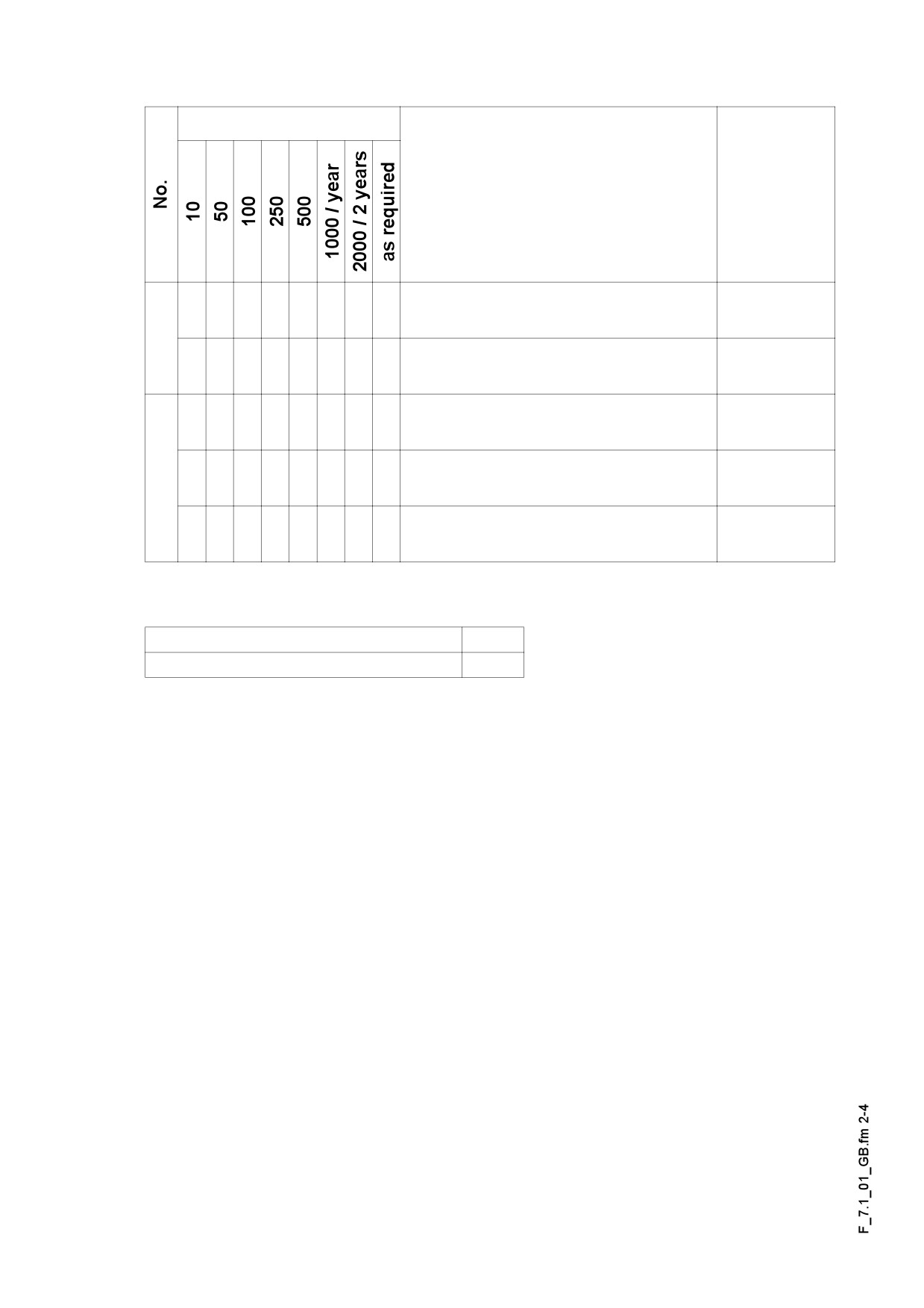
Maintenance intervals
Interval
Points of maintenance
Remark
- Chain tightness
q
Inspection
1
- Chain tightness
q
setting
- Planetary gear
q
oil level check
- Planetary gear
2
q
topping up the oil
- Planetary gear
q
oil change
Maintenance
q
Maintenance during run-in period
g
F 7.1 2
1.2
Points of maintenance
Track tightness (1)
Slack tracks may slip out of the guides of
m
the rolls, drive and guide wheels and in-
tensive wear may take place.
Too tight tracks add to the wear of guide wheels and drive bearings, the pins and
m
bushes of the tracks as well.
Track tension: checking / adjusting:
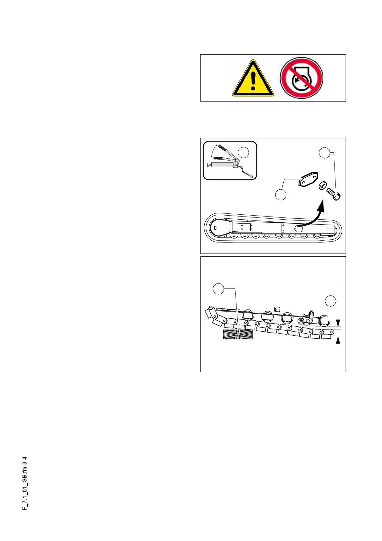
x
A
- Track tightness can be adjusted with
grease press. The filling ports are lo-
cated on the LH and RH sides of the
running gear.
- Run paver drive unit onto a suitable
B
piece of angled timber (C) or onto a
similar object.
- To relieve strain on the track, reverse
a short distance, ensuring that the ve-
hicle remains on the angled timber.
LW_DYN2.bmp
The tack is correctly tensioned once the
A
slack (F) between centre roller and track
is 30-40 mm.
C
If a different level of slack is detected
A
F
during the measurement process, pro-
ceed as follows:
- Drive the vehicle forwards slightly, to
relieve strain on the upper track sec-
tion.
- Remove the screws (A).
Spann_LWDyn.bmp
- Remove cap (B).
- Screw the head module of the flat grease nipple (toolbox) on the grease press.
- Fill the track tensioner with grease, then remove the grease gun.
- Next, drive the vehicle forwards and backwards a few times.
- Check the track tension once again, as described above.
Repeat this procedure on both drive units!
A
- Remount the lid (B).
F 7.1 3
Planetary gear (2)
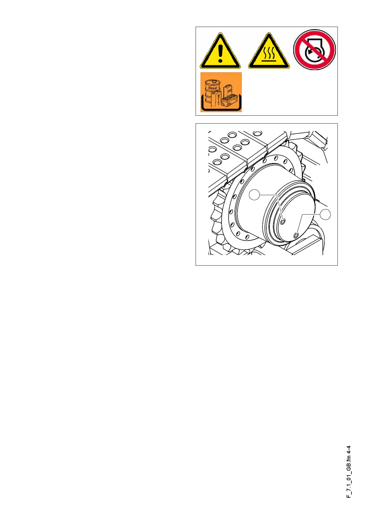
- For checking the oil level unscrew the
inspection plug (A).
In case of proper oil level, the oil is at the
A
lower edge of the inspection port or a lit-
tle oil flows from the hole.
For filling in the oil:
- Remove filling plug (A).
- Fill oil of the correct specification
through the filling hole (A) until the oil
level reaches the lower edge of the fill-
ing hole (A).
- Replace the cap (A).
Oil change:
A
Change the oil when the engine is at op-
A
erating temperature.
B
Make sure that no pollution or foreign
m
matter gets into the drive.
Gear.bmp
- Turn the drive so that the „oil max“
mark stands horizontally and the drain
screw plug (B) is at the bottom.
- Unscrew the drain plug (B) and the filling plug (A) and drain the oil.
- Check and replace the seals of both screw plugs.
- Return plug (B).
- Fill in new oil through the filling port until the „oil max“ mark is achieved.
- Drive in filling plug (A).
F 7.1 4
F 8.1
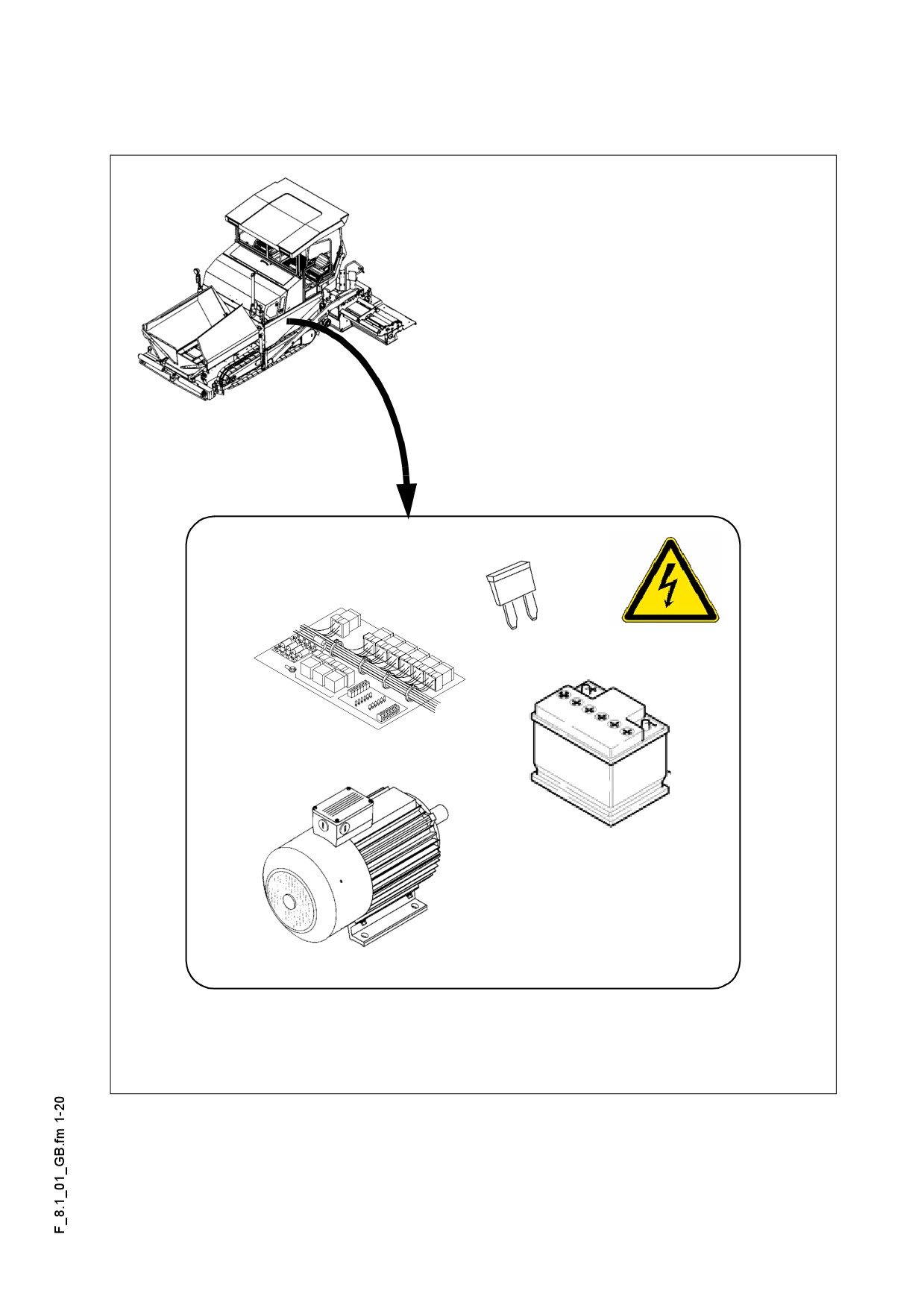
Maintenance - Electronic System
1
Maintenance - Electronic System
F 8.1 1
1.1
Maintenance intervals
Interval
Points of maintenance
Remark
Check
q
the level of battery electrolyte
1
q
Top up with ion exchanged water
q
Coat the battery poles with grease
Maintenance
q
Maintenance during run-in period
g
F 8.1 2
Interval
Points of maintenance
Remark
Also see
-
Generator
the opera-
Checking of operation of the insu-
q
tion manu-
lation monitoring of electric equip-
al of the
ment
screed
-
Generator
Visual checking for pollution or
damage
q
(o)
-
Check the cooling air openings
for pollution or clogging, clean as
required.
-
Generator
Check the ball bearings "by lis-
q
(o)
2
tening" and replace them as re-
quired.
-
Generator
q
q
(o)
Replacement of ball bearings
-
Generator
q
Check the drive belts (o) for inju-
(o)
ry and replace them as required.
(o)
-
Generator
Only on
q
Drive belts (o) - check tightness
version with
and adjust as required.
V-belt!
-
Generator
q
(o)
Replacement of drive belts (o)
Maintenance
q
Maintenance during run-in period
g
F 8.1 3
Interval
Points of maintenance
Remark
3
q
Electric fuses
Maintenance
q
Maintenance during run-in period
g
F 8.1 4
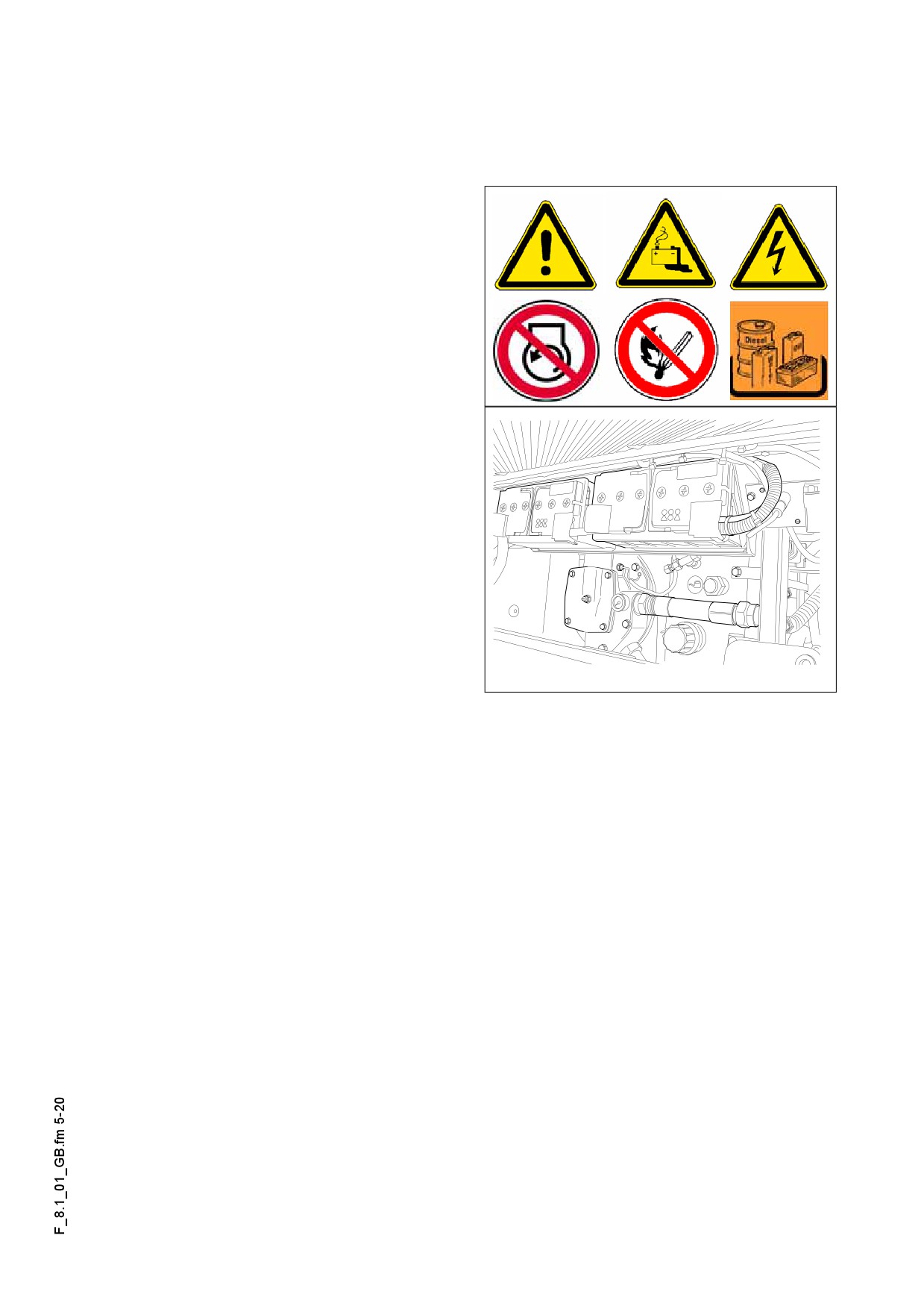
1.2
Points of maintenance
Batteries (1)
Maintenance of storage batteries
The batteries are filled with the appropri-
ate volume of electrolyte in the factory.
The electrolyte level shall be up to the
top mark. Top up with ion exchanged
water only, when required!
The shoes shall be free of oxyde and
coated with special battery protection
grease.
m When removing the batteries always
separate the minus pole first and avoid
short circuit between the battery poles.
Tankhood_LH.eps
F 8.1 5
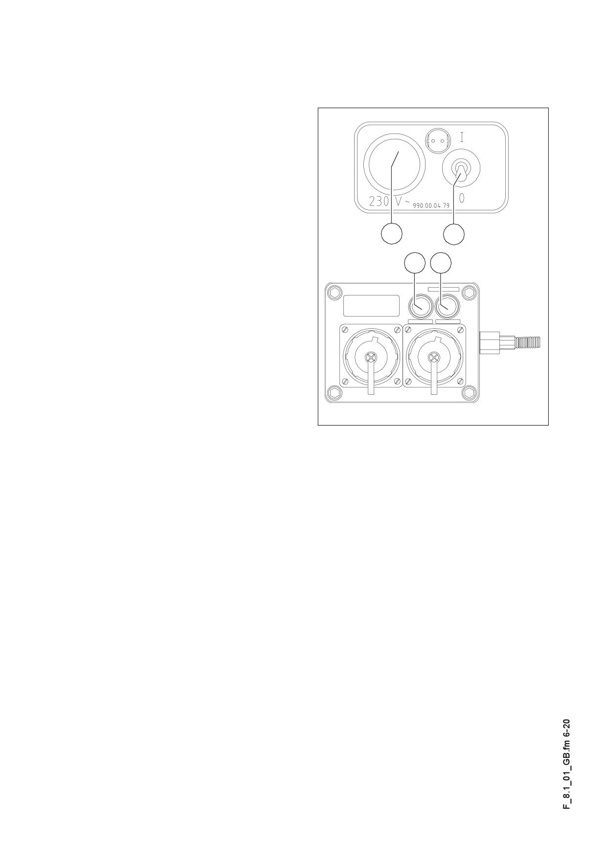
Generator (2)
Checking of operation of the insulation monitoring
Check insulation daily with operating
A
machine and switched on connection
sockets.
- Turn on the electrical equipment with
switch (1), control light (2) comes on.
- Press testing button (3) and the in-
scription "Isolationsfehler - Insulation
Fault" shall come on.
2
1
- Depress the button clear (4) and the
insulation fault inscription will go dark.
3
4
If the test is completed successfully,
f
work can proceed with the electrical sys-
tem and external consumers can be
used.
If the "Insulation Fault" control light indi-
cates a fault already before pressing the
control button, then work cannot pro-
ceed with the electrical system and the
external consumers. In case of insula-
Schalt_230V.wmf/230V.wmf
tion fault the connection sockets are au-
tomatically turned off.
Work with the electric system cannot proceed if the simulation does not indicate a fail-
ure.
In case of failures, the electric equipment needs to be tested and repaired by an elec-
f
trician. With these devices and the equipment work can be resumed only after such
test and repair.
Danger from electric voltage
Failure to comply with the safety precautions and safety regulations can result
in electrical shock injuries from the electrical system.
Danger to life!
All maintenance and repair work on the electrical system must always be car-
ried out by an electrician!
F 8.1 6
Checking of ball bearings / Replace-
ment of ball bearings
A Report the displayed fault code to the
customer service of the paver finisher
and they will discuss with you the steps
to be taken.
F 8.1 7
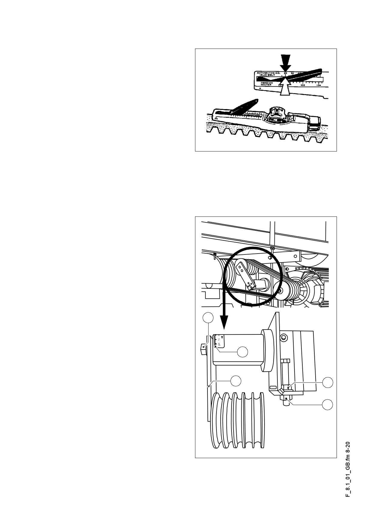
Drive belts (V-belt)
Checking belt tension
The tightness of each belt shall be in-
spected with a tightness checking instru-
ment.
Specified tension:
- in case of first assembly: 550 N
- after run-in period /
maintenance interval: 400N
Riemensp.tif
A Instructions for checking of tightness in
the description of the tightness measuring instrument.
A The tightness measuring instrument can be ordered according to the Article No.
532.000.45!
Adjustment of belt tightness
- Release locking screw (A) that the
bracket
(B) of the tightening roller
comes to position zero (scale (C) =
0°).
- For the adjustment of the locking de-
vice loosen or turn the appropriate nut
(D) or counter-nut (E), until the tight-
ening roller contacts the loosened up-
per belt.
- Turn the bracket of the tightening roll
A
(B) to adjust the correct tightness, to-
wards the upper belt (scale (C) = 15°).
- Retighten locking bolt (A).
C
- Retighten the previously loosened nut
(D) or (E).
Replace the pump
B
E
- Reduce the belt tightness on the ad-
D
justing device so that the belt can be
removed from the pulley.
- Mount the new belt and adjust tight-
ness again.
Always replace the belts in sets.
A
Generator_belt.wmf/Generator_spann.wmf
F 8.1 8
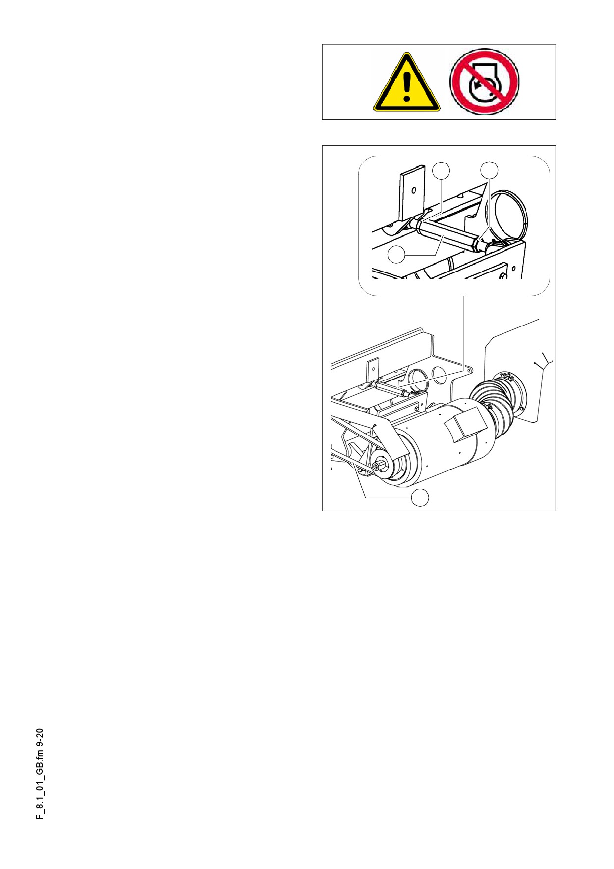
Drive belt (toothed belt)
Replacement of belt
A
A
- Unfasten both lock nuts (A) from the
clamping lock.
- Rotate and open clamping lock (B) un-
til belt (C) can be replaced.
A Pre-tension newly fitted belt using
B
clamping lock (B).
- Checking / adjusting belt tension
B
Riemenspann.jpg
F 8.1 9
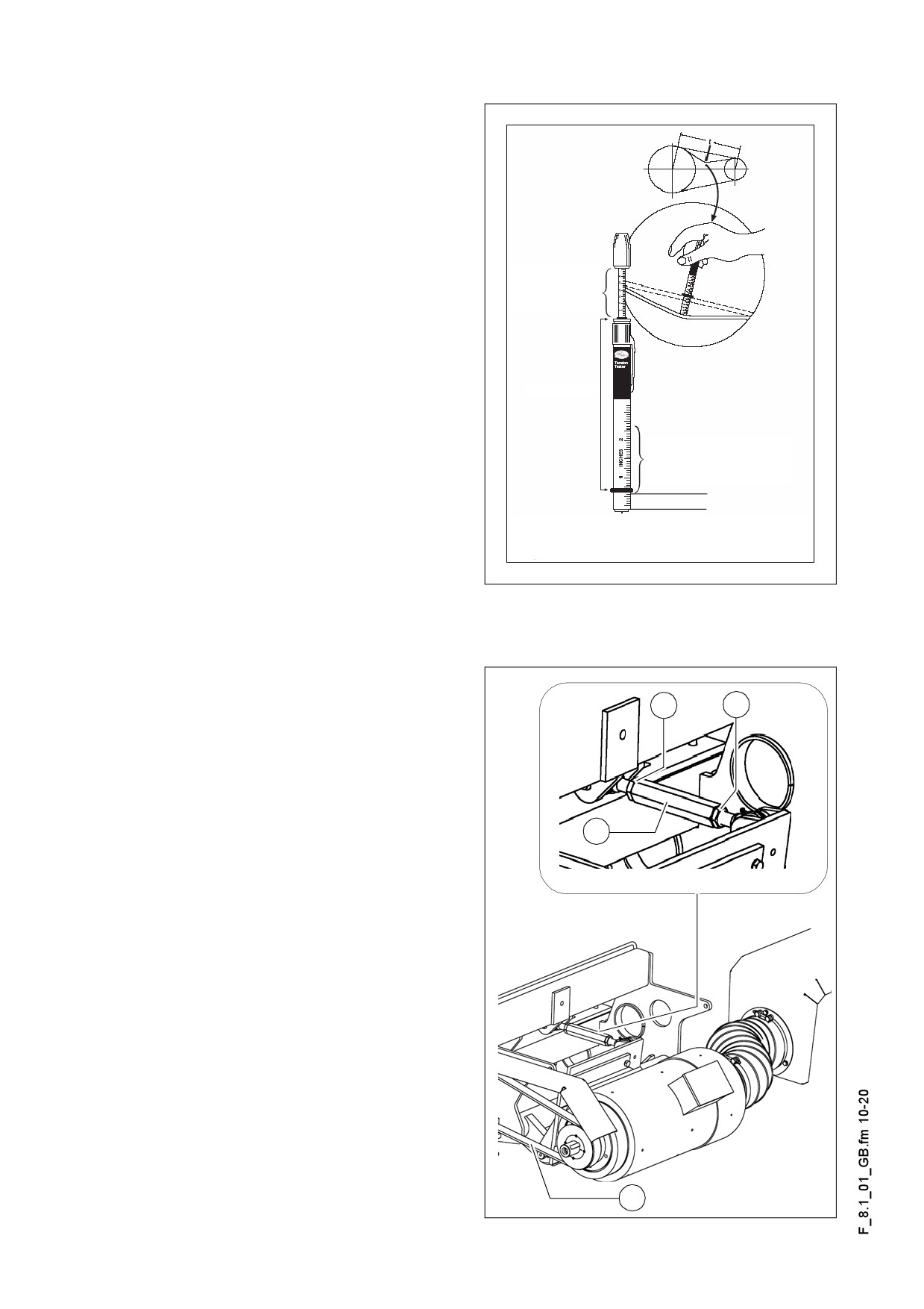
Checking / adjusting belt tension:
The tension of the V-belt must be
A
checked and set after the belt has been
replaced.
- The tension of the belt can only be ad-
justed using a pre-tensioning test de-
vice.
Deflection
Specified belt tension levels:
(read from
bottom to top)
- Generator 17KVA:
- Deflection force, min: 101.4N
- Deflection force, max: 110.6N
Rubber rings
Deflection
- Belt deflection approx. 9.9mm
- Generator 20KVA:
Redirection
- Deflection force, min: 72.4N
(read from
- Deflection force, max: 79.0N
bottom to top)
- Belt deflection approx. 5.4mm
Belt deflection
Read off directly below the ring. Before you use the
- Generator 28KVA:
voltage tester again, slide the ring back down again.
- Deflection force, min: 92.2N
Riemenspann.jpg
- Deflection force, max: 100.5N
Belt deflection approx. 5.4mm
A
If necessary, adjust the belt tension:
A
A
- Set belt to correct tension using
clamping lock (B).
- Retighten both lock nuts (A).
Further instructions for checking of ten-
A
sion - see description of the belt pre-ten-
B
sioning test device.
A belt pre-tensioning test device can be
A
ordered from Dynapac as a spare part!
Item number on request.
B
Riemenspann.jpg
F 8.1 10
Electric fuses (3)
Type of machine: Conventional electronics
Switch box
B
C
A
Fuses_635_konv.eps
A
Main fuses
B
Fuses in the switching cabinet
C
Relays in the switching cabinet
Main fuses (A)
F.
A
3.1
Main fuses
50
3.2
Reserve
50
F 8.1 11
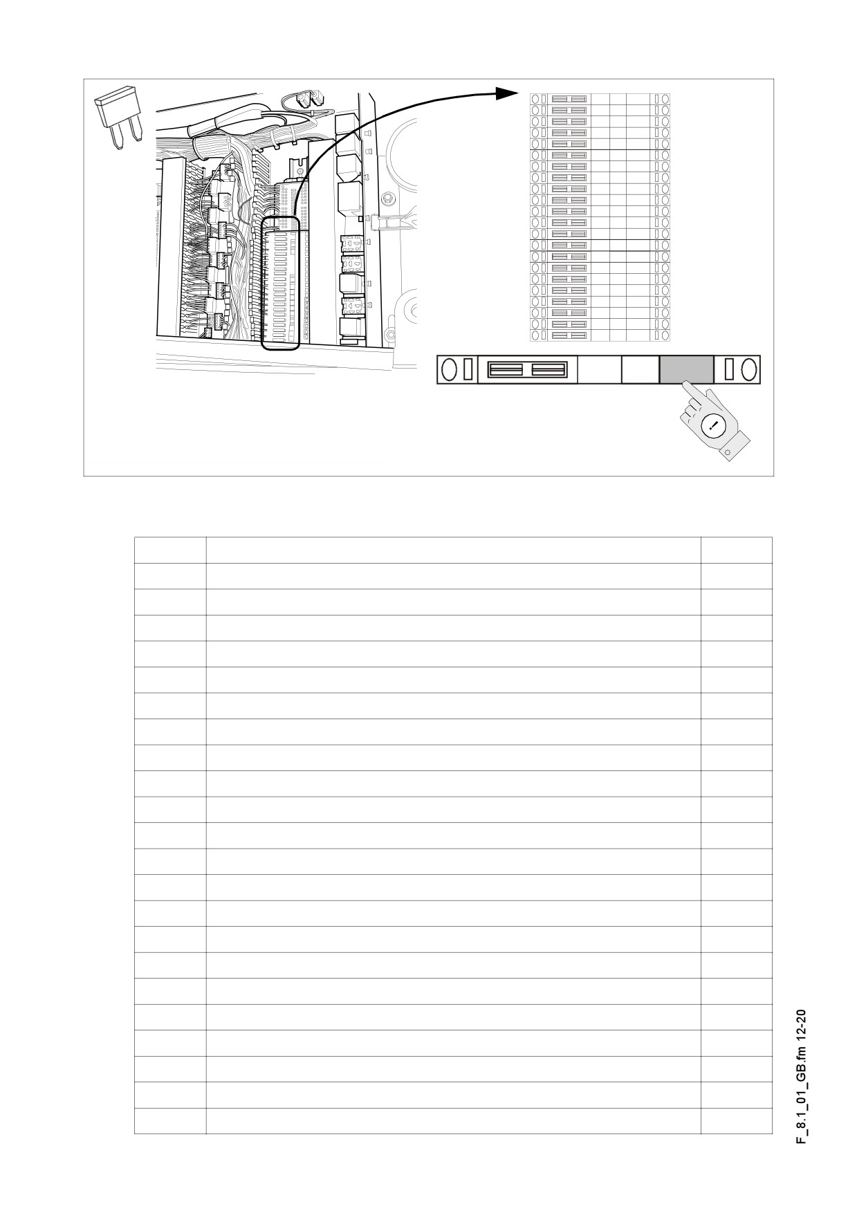
Fuses in the switching cabinet (B)
F5.5
F.
A
5.1
Machine drive
15
5.2
Machine drive
1
5.3
Temperature control, electric heating
10
5.4
Gas heating
10
5.5
Connection sockets with On-Off switch buttons
10
5.6
Connection sockets with On-Off switch buttons
10
5.7
Connection sockets with On-Off switch buttons
10
5.8
Connection sockets with On-Off switch buttons
10
5.9
Starting the engine
10
41
Engine regulation
25
44
Machine drive
1
51
Spray equipment
3
52
Emulsion spray appliance
3
53
Diesel fuel pump
5
54
Flasher
3
55
Headlight (glass fibre reinforced roof)
10
59
Working floodlights (o)
15
82
Particle filter (o)
3
83
Exhaust equipment (o)
3
84
Seat heating
10
85
Windscreen wiper
7,5
86
Reserve
10
F 8.1 12
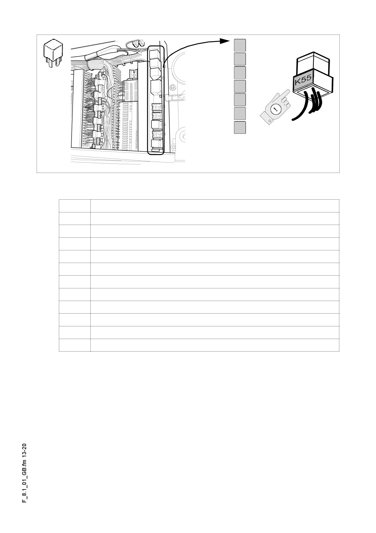
Relays in the switching cabinet (C)
K
15
Starting the engine
18.2
Retracting the screed on the right hand side
18.1
Retracting the screed on the right hand side
94
Power supply, terminal 15
145
Engine regulation
88
Complementary emergency stop
53
free
52
free
44
Re-compressor
42
Machine drive
11
Engine regulation
F 8.1 13
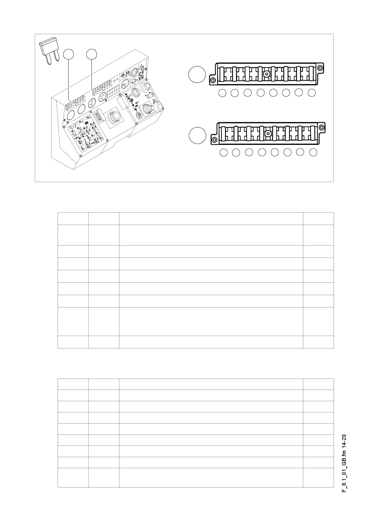
Fuses on the operating panel
A
B
A
1
2
3
4
5
6
7
8
B
1
2
3
4
5
6
7
8
Bedienpult_konv_Kette_635_Fuse1/Fuse1.tif/Fuse.bmp
Fuse carrier (A)
No.
F.
A
Engine start, start button interlock, idling speed, re-
1.
1.1
5
verse indicator
2.
1.2
Interlocking relay, Bat 15+ relay, monitoring systems
3
3.
1.3
Levelling, screed stopping
5
4.
1.4
Conveyor, RH-side auger
5
5.
1.5
Conveyor, LH-side auger
5
6.
1.6
Tamper, vibration
3
Hopper, screed lift and lowering, screed retraction/ex-
7.
1.7
tension, screed power supply, re-compression lift (o),
10
cabin movement (o), auger lifting/lowering (o)
8.
1.8
Emergency stopping
7.5
Fuse carrier (B)
No.
F.
A
1.
2.1
free
2.
2.2
Horn
5
3.
2.3
Road profile
7,5
4.
2.4
Headlights on the left/right sides
7,5
5.
2.5
RH-side low beam headlight
3
6.
2.6
LH-side low beam headlight
3
7.
2.7
RH-side position light
3
LH-side position light, instrument panel light, instru-
8.
2.8
3
ment light
F 8.1 14
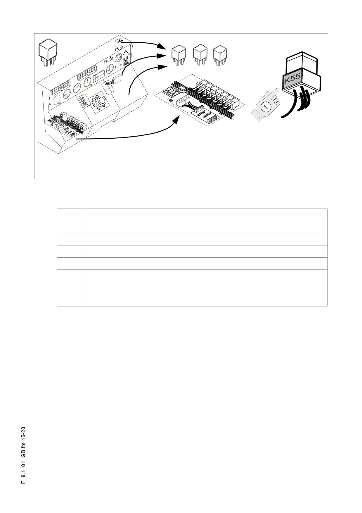
Relays on the operating panel
Bedienpult_konv_Rad_656_Fuse3.wmf
Relays (A)
K
31
Emergency stopping (VB805/1105, EB50,75)
17
Screed functions
12
Conveyor / LH-side auger
13
Conveyor / RH-side auger
33
Engine regulation
81
free
82
free
F 8.1 15
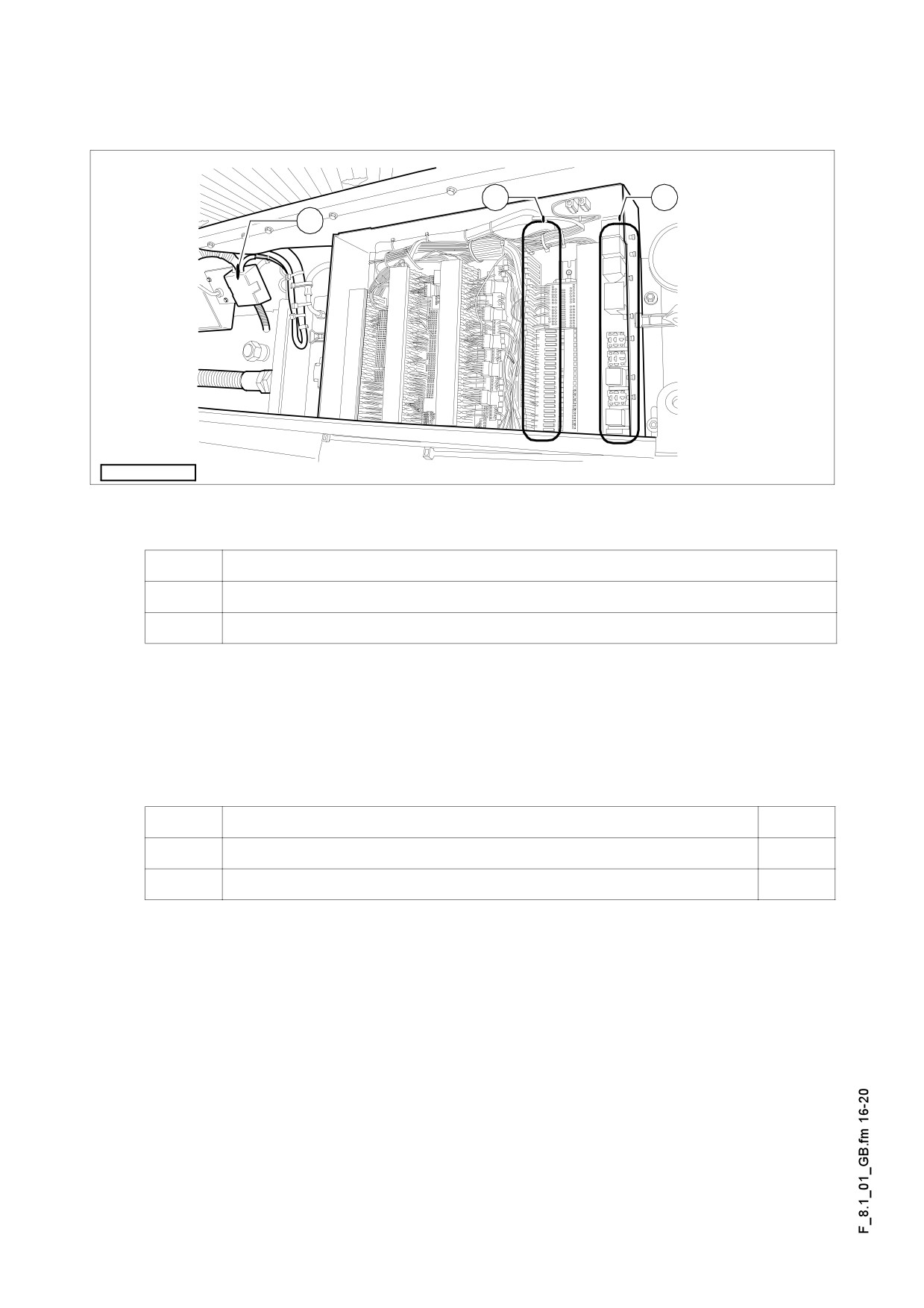
Type of machine: PLC- electronics
Switch box
B
C
A
Fuses_635_konv.eps
A
Main fuses
B
Fuses in the switching cabinet
C
Relays in the switching cabinet
Main fuses (A)
F.
A
3.1
Main fuses
50
3.2
Reserve
50
F 8.1 16