DYNAPAC Paver finisher F 121 C, F 141 C Type 635. Operation & Maintenance (Order number: 4812026925) - page 4
2.5
Special functions
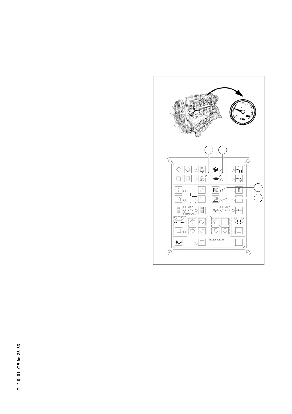
Emergency operation program for the case of keyboard failure
To ensure the pavers operating ability during a display failure, an emergency program
will be started automatically.
Following setting and functions will be
max min-1
adjusted and switched on:
- Number of revolutions of the Diesel
engine: 1800 min-1
- Traction drive (1) slow (Tortoise)
- Operating main switch (2) OFF
- Tamper (3) switched on
- Vibration (4) switched on
Connected functions will not be indicat-
2
1
m
ed by LED during a display failure!
Tamper and vibration can be deactivat-
A
ed by the associated rotary potentiome-
ter (set to „zero“).
3
The frequency of the tamper and vibra-
tion can be read off the two associated
4
displays (O).
Deutz2013L06.tif,RPM.tif,Element1_SPS_Kette_635.wmf
D 2.0 35
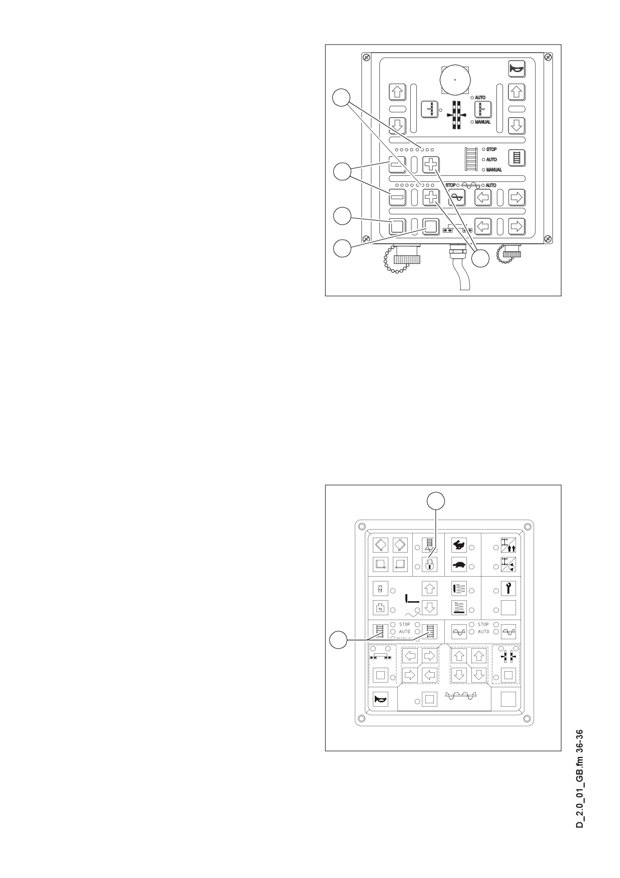
Accessory the following function can be
switched by using the remote controls:
- Press button (1) to close the hopper.
3
- Press button (2) to open the hopper.
- Lifting the screed:
- Switch off the LED bar (3) of auger
and conveyor completely by using
the accompanying Minus-buttons
4
(4).
- Lift the screed infinitely variable by
using both Minus-buttons(4) simulta-
1
neously.
- Switching the screed into readiness
2
5
(floating position):
- Switch the LED bar (3) of auger and
Remote_SPS_neu1.cdr
conveyor completely on by using the
accompanying Plus-buttons (5).
- Switch the screed into floating position by pressing both Plus-buttons (5) simulta-
neously.
The screed sinks immediately.
m
To lift the screed out of floating position, the LED bar of auger and conveyor must be
A
deleted again.
Reversible conveyor
16
The direction of transport of the convey-
or can be changed over to the opposite
direction to move material located just in
front of the auger back slightly. Material
losses, e.g. during transport operations
can therefore be avoided.
- Switch main function switch (16) over
to „Off“ switch position (LED off).
32
- Hold down one or both of the buttons
(32) in the „STOP“ switch position for
approx. 5 seconds.
The system jumps into the „Manual“
switch position and the conveyor
moves approx. 1 metre towards the
hopper. The system then jumps back
Element1_SPS_Kette_635.wmf
into the „Stop“ switch position.
If necessary, this process can be repeated as many times as required to allow the
conveyor to move further in the opposite direction.
D 2.0 36
D 3.1
Operation
1
Operating elements on the paver finisher
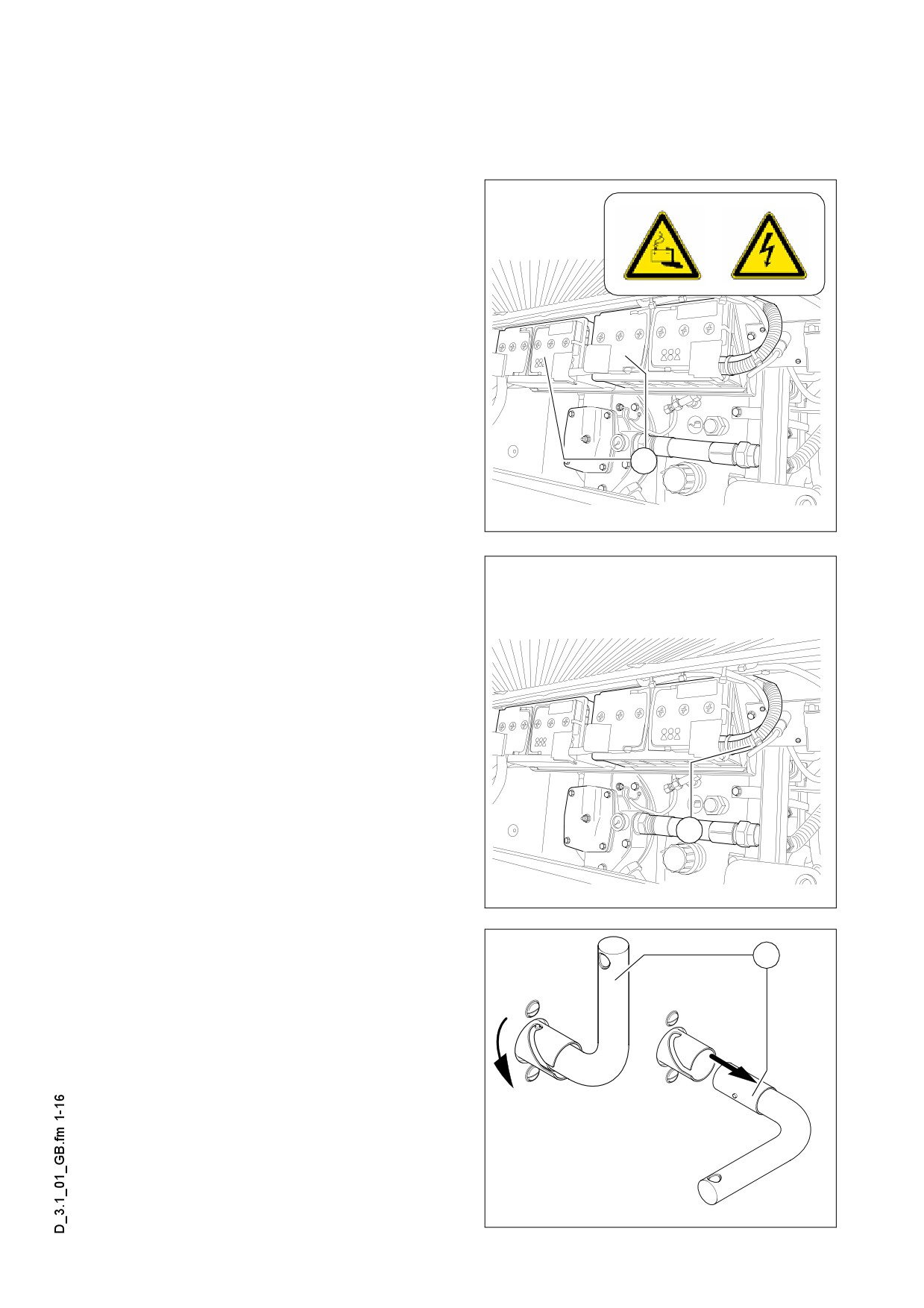
Batteries (71)
The batteries of the 24 V system are lo-
cated under the left maintenance flap.
For the specifications, refer to chapter B,
A
”Technical Data”.
For servicing, see chapter F.
Heed the instructions when starting the
m
paver finisher externally.
(see section
“Starting the paver finisher, External
starting (starting aid)“).
71
Tankhood_LH.eps
Battery main switch (72)
The main switch interrupting the circuit
between the battery and the main fuse is
located under the left maintenance flap.
For the assignment of all fuses, see
A
chapter F.
- For switching off, turn the key (72) to
the left and pull it out.
Do not lose the key as in this case the
A
72
paver finisher can no longer be moved!
Tankhood_LH.eps
72
F0077_A1.EPS/F0078_A1.EPS
D 3.1 1
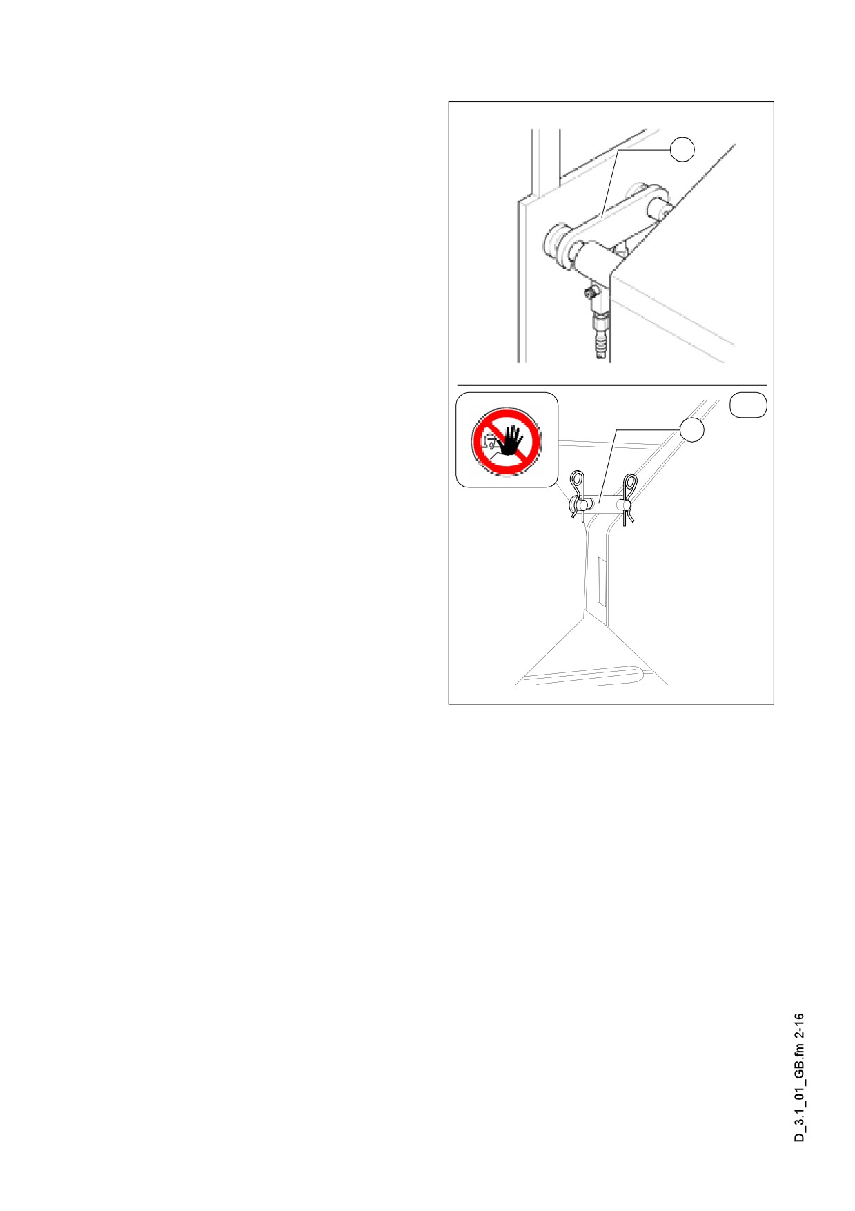
Transport safeguards for the hopper (73)
Before parking or transporting the paver
finisher, the hopper halves must be
swung upwards and the transport safe-
a
guards for the hopper must be inserted.
Item:
-
(a) - outside on the two half-hoppers
or
-
(b) - in the feeding hopper (o)
f Do not enter the hopper while the engine
is running! Danger of being caught by
the conveyor!
(o)
Without transport safeguards inserted,
b
the hopper halves will slowly open; dan-
ger during transportation!
Hopperlock2.tif/Hopperlock_SK.eps
D 3.1 2
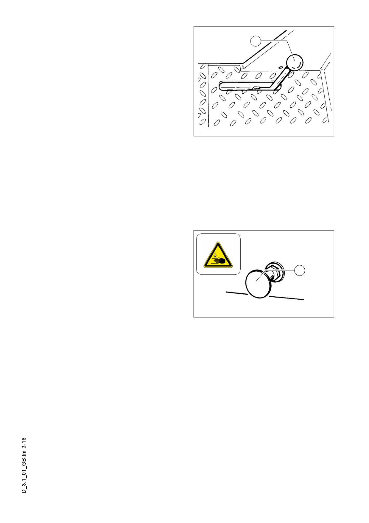
Mechanical screed transport safe-
guard (to the left and the right be-
74
neath the driver’s seat) (74)
Used to protect the lifted screed from in-
advertent lowering. The screed transport
safeguard must be inserted before trans-
portation and when work is finished.
f Transportation with an unsecured
screed bears the danger of accidents!
F0083_A1.TIF
- Lift the screed.
- Actuate the levers.
- Check that the latches (to the left and to the right) engage in the crossbeams.
m ATTENTION!
Insert screed lock only at crown adjustment „zero“! Screed lock only for transportation
Use the interlocking of the main girder for transportation only!
Do not enter or work under screed only secured with screed lock for transportation!
Danger of accident!
Seat lock (behind the driver’s seat)
(75)
Telescoping seats (o) can be extended
beyond the basic width of the paver fin-
75
isher. They must be locked.
f The seats must not protrude from the ve-
hicle during transportation. Push the
seats back to the basic width of the pav-
F0169_A1.EPS
er finisher!
- Pull out the locking button and move the seat; let the locking button engage again.
f The driver’s seat can move when the locking button is not engaged properly. Danger
of accidents during transportation!
D 3.1 3
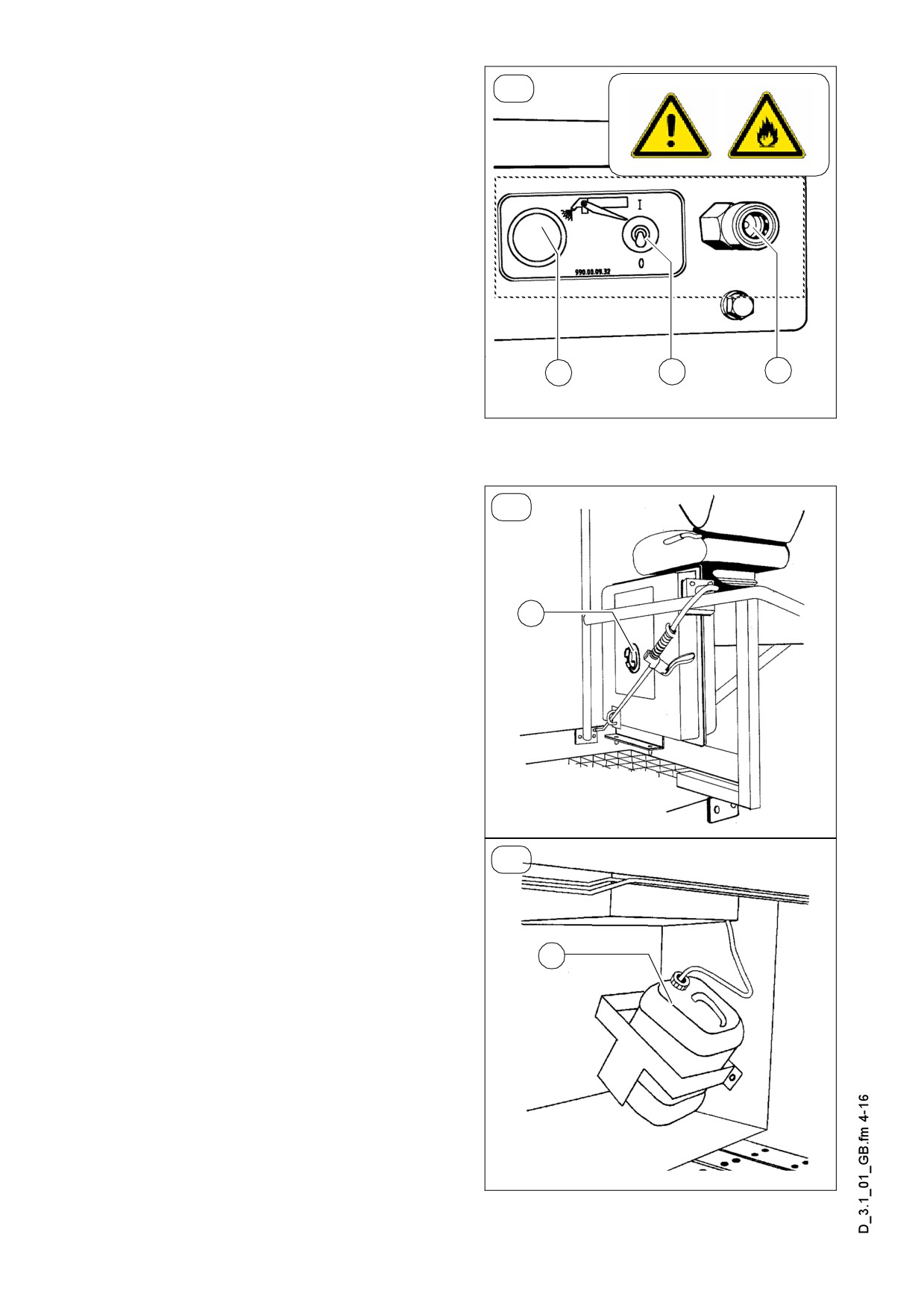
Separator fluid spraying system (80)
(o)
(o)
Used to spray the parts coming into con-
tact with asphalt with a separator emul-
sion.
- The indicator lamp (A) lights up when
the emulsion pump is running
- On/off switch
(B) for the emulsion
pump
- Quick-release coupling (C) for hose
connection
A
B
C
Only switch on the spraying system
m
when the diesel engine is running; other-
Emu2.tif
wise, the battery will be discharged.
Switch off after use.
A permanent installed hose guide (D) for
A
(o)
the fluid spraying system is available as
an option.
Pull hose out of the guide till there is an
audible creak. The hose will engage in
D
this position after discharging.The hose
will be retracted automatic into the guide
after pulling and discharging again.
Don’t spray into open flame or on hot
f
surface! Danger of explosion!
Emul1.Tif
A The spraying system is feeded by a can
(o)
(E) under the side flap on R.H. side.
f Refill the can only while standstill of the
paver finisher!
E
Emu3.tiff
D 3.1 4
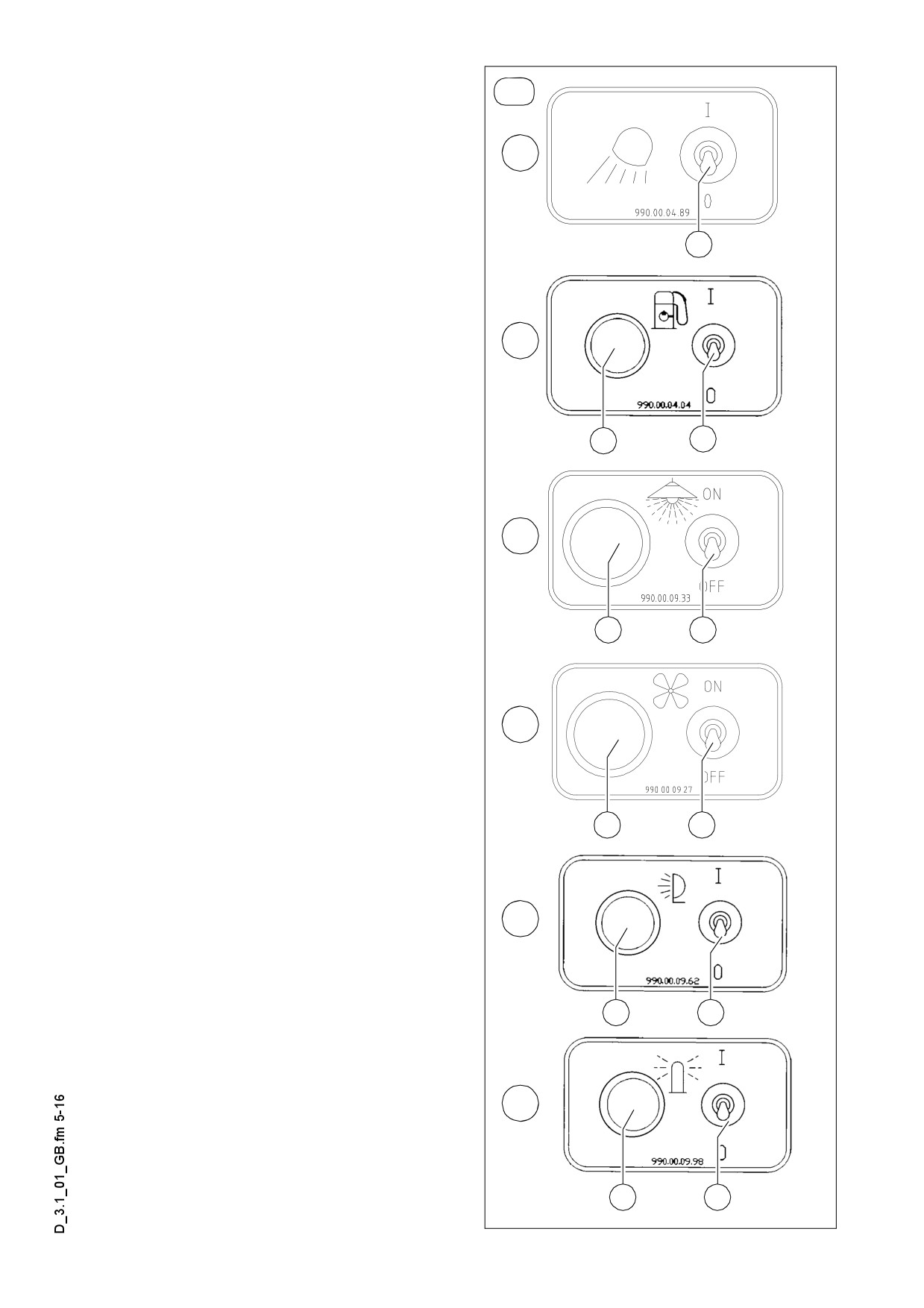
Further switch options for optional
A
equipment features may be located on
(o)
the central panel:
85
On / off switch for additional head-
light in the roof (85):
Actuate switch (a) to activate.
a
On / off switch for fuel tank filler
pump (85a)
85a
If the pump is actuated with the switch
(a), the indicator lamp (b) lights up.
When fuelling, ensure that no fuel pene-
f
b
a
trates the earth. Switch off the engine
and do not smoke. Do not fuel in en-
closed spaces. Danger to health! Have a
fire extinguisher ready.
85b
On / off switch special lighting (85b)
If the machine is equipped with addition-
b
a
al headlights, these are actuated by
means of the switch (a). When switched
to the „ON“ position, the indicator lamp
(b) lights up.
85c
Switch the additional headlights and
m
special lighting off when the engine is
not running, as the battery is otherwise
discharged!
b
a
On/Off switch
Exhaust of asphalt vapours (85c)
85d
In case of the availability of optional as-
phalt vapour exhaust system, this can
be turned on by switch (a).
In the switch position „ON“ the control
b
a
light (b) is on.
85e
b
a
D 3.1 5
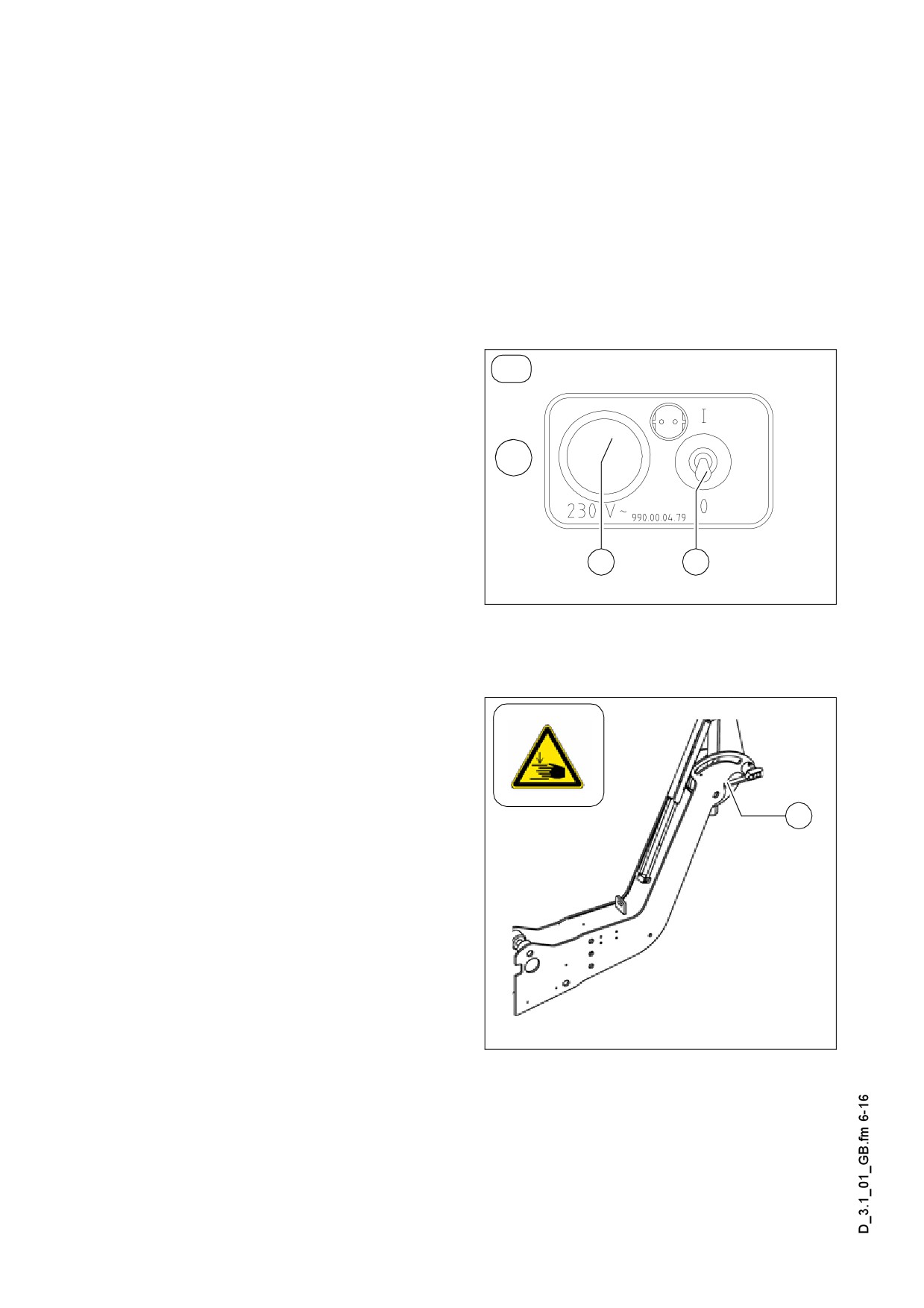
On/Off switch of work headlights (85d):
Actuate switch (a) to switch on.
In the switch position „ON“ the control light (b) is on.
On/Off switch of flasher (85e):
Actuate switch (a) to switch on.
In the switch position „ON“ the control light (b) is on.
A If the optionally available 230 V systems
(o)
is installed, an additional switch cabinet
is mounted on the paver finisher:
85f
230 V On / Off switch
Connection sockets (85f)
In case of being equipped with 230 V ac-
cessories, the connection sockets can
b
a
be powered through switches (a). In the
switch position „I“ the control light (b) is
Schalt_230V.wmf
on.
Locking of the collapsible roof (LH
and RH on the roofs console) (86):
To lower the roof (for example during
transport on a low bed trailer):
A
- Loose the twistlock (A)
- Pull the roof frame forward holding the
clevis or the frame
- Arrest the twistlock in the second lock-
ing hole.
Dachkons.bmp
D 3.1 6
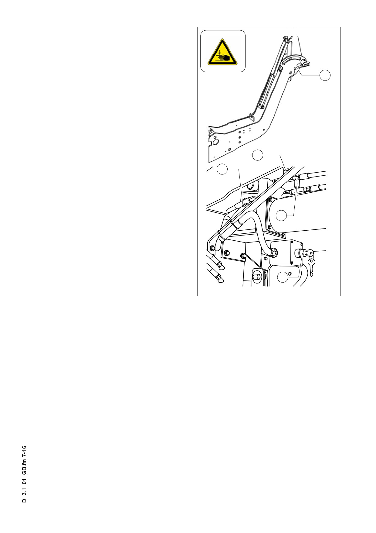
Hydraulic folding roof (87) (o)
The hydraulically folding roof is secured
by means of a latch (A) at the rear sus-
pension on the left and right sides of the
machine. This must be released prior to
A
lowering and raising. Once it has
reached its terminal position, the roof
must be secured with the latch again.
The hydraulic unit and the key-operated
switch (A) for actuating the folding roof
hydraulic system are located on the left
side of the paver finisher's rear panel.
The roof can be raised and lowered with-
D
A
out having to start the drive motor.
C
- In order to lower the roof, turn the key-
operated switch (B) to the right until
the roof has been lowered to its mini-
mum level.
E
Danger of crushing! Ensure that nobody
f
inserts their fingers or hands into the
joint areas or are placed at risk by the
lowering roof during the folding proce-
dure.
B
- In order to raise the roof again, turn
the key-operated switch (B) to the left
Dachkons.bmp/Dach_Hydr.wmf
until the roof has been raised to its
maximum height.
If it is necessary to raise the roof whilst the battery is discharged, a manual pump is
available on the hydraulic unit.
- Actuate the pump lever (C) until the roof can be secured with the latch bolt (A) in its
uppermost position.
Two throttles are installed to adjust the raising and lowering speed:
- Throttle valve (D): Adjust roof raising speed.
Turning the adjusting knob in the clockwise direction = lower speed.
Turning anti-clockwise = higher speed.
- Throttle valve (E): Adjust roof lowering speed.
Turning the adjusting knob in the clockwise direction = lower speed.
Turning anti-clockwise = higher speed.
D 3.1 7
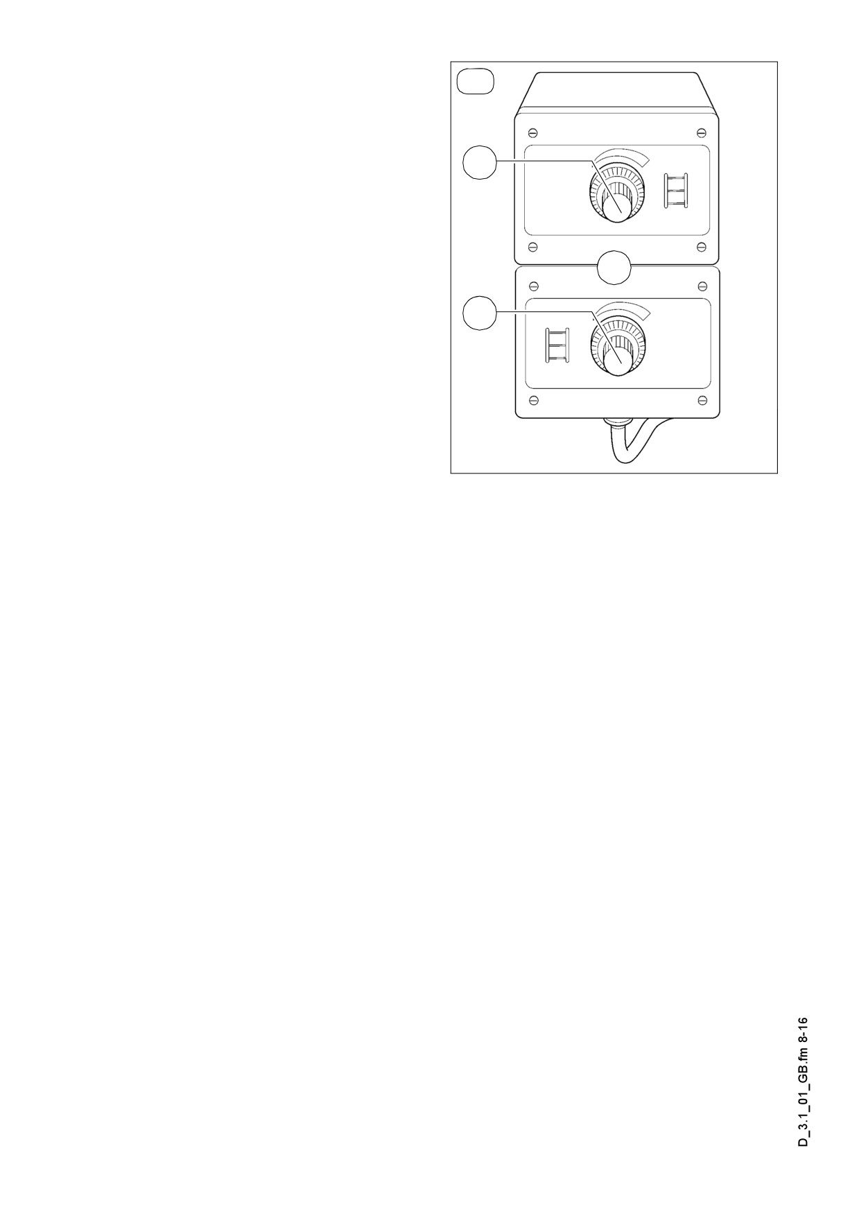
Electric setting of the transportation
(o)
volume of the conveyor (o) (88)
With this the transport volume of the
conveyor can be adjusted when me-
88a
chanical limit switch or ultrasonic sensor
is used.
- The „0“ position of the scale corre-
sponds to the smallest adjustable vol-
ume.
85d
- RH-side conveyor: (88a)
- LH-side conveyor: (88b)
88b
F0091_A1.EPS
D 3.1 8
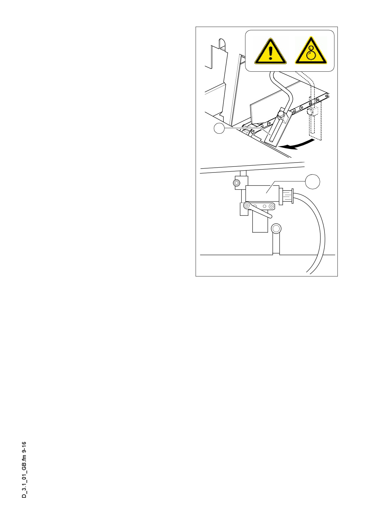
Conveyor limit switches (89)
The mechanical conveyor limit switches
(89) or the ultrasonic conveyor limit
switches
(89ao) control the material
flow at the respective conveyor half.
The conveyors should stop when the
material has roughly reached the area
below the auger tube.
A This requires that the auger height has
been adjusted correctly (see chapter E).
89
89a
F0114_A1.EPS/Ultra3.EPS
D 3.1 9
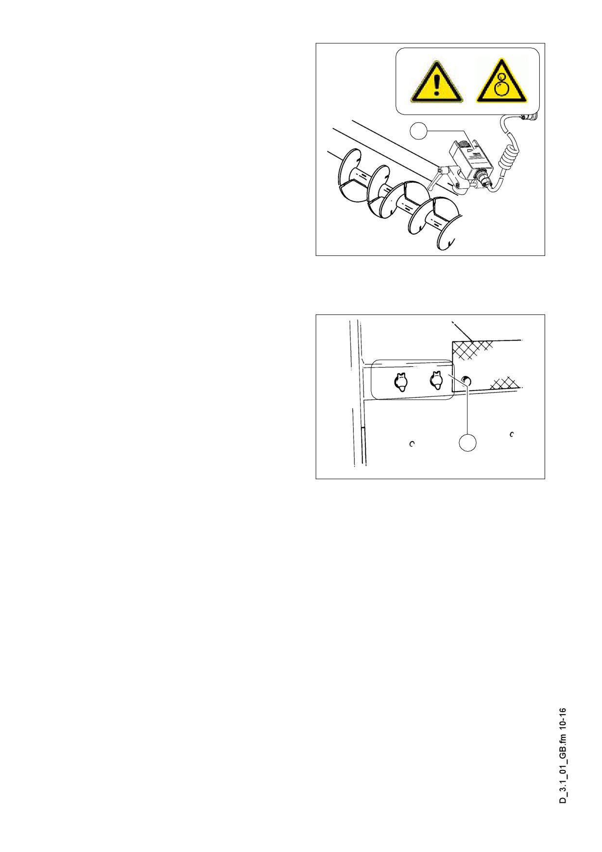
Ultrasonic auger limit switches (90)
(left and right)
A The limit switches control the material
flow at the respective auger half.
90
The ultrasonic sensor is mounted by
means of an appropriate leverage to the
side plate. Loose clamping lever for ad-
justment and modify angle / height of the
sensor.
The cables must be connected to the re-
mote control units located at the sides of
the screed (socket (62)).
Ultra_Auger.bmp
A We recommend to adjust the limit switch
positions while the material is distributed.
Sockets for working lights (left and
right) (92)
Connect the working lights (24 V) here.
- Power is present when the main
switch (72) is switched on.
A As an option, one socket can be used to
provide power for an electrically heated
92
seat.
F0124_A1.TIF
D 3.1 10
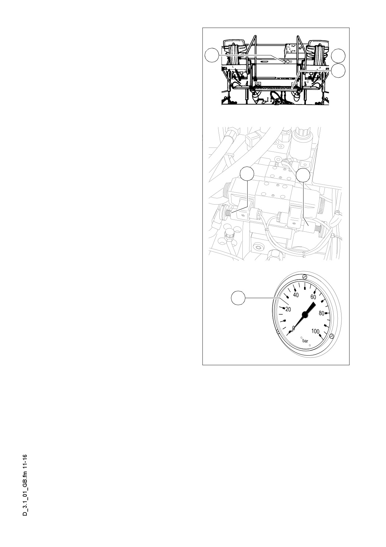
Pressure control valve for screed
charging/relieving (93)
93b
93
Used to adjust the pressure for addition-
al charging/relieving of the screed.
93a
- See
”screed charging/relieving de-
vice”.
(Chapters „Operating Panel“, „Opera-
tion“).
- Pressure display: see pressure gauge
(93b).
Pressure control valve for screed
stop with pretensioning (93a)
93
93a
This valve is located beneath the right-
hand bottom flap of the operator´s plat-
form.
It is used to adjust the pressure for
”screed stop with pretensioning”.
- Activation: see
“screed charging/re-
lieving device” (34).
- Pressure display: see
“pressure
gauge” (93b).
93b
Pressure gauge for screed charging/
relieving and screed stop with preten-
sioning (93b)
Displays the pressure for
F0184_A1.TIF/Screed_Valve.eps/F0105_A1.TIF
- Screed stop with pretensioning screed
stop with pretensioning when the drive lever is set to the neutral position (pressure
to be adjusted using valve (93a));
Screed charging/relieving device when the drive lever is in the third position (pressure
to be adjusted using valve (93)).
D 3.1 11
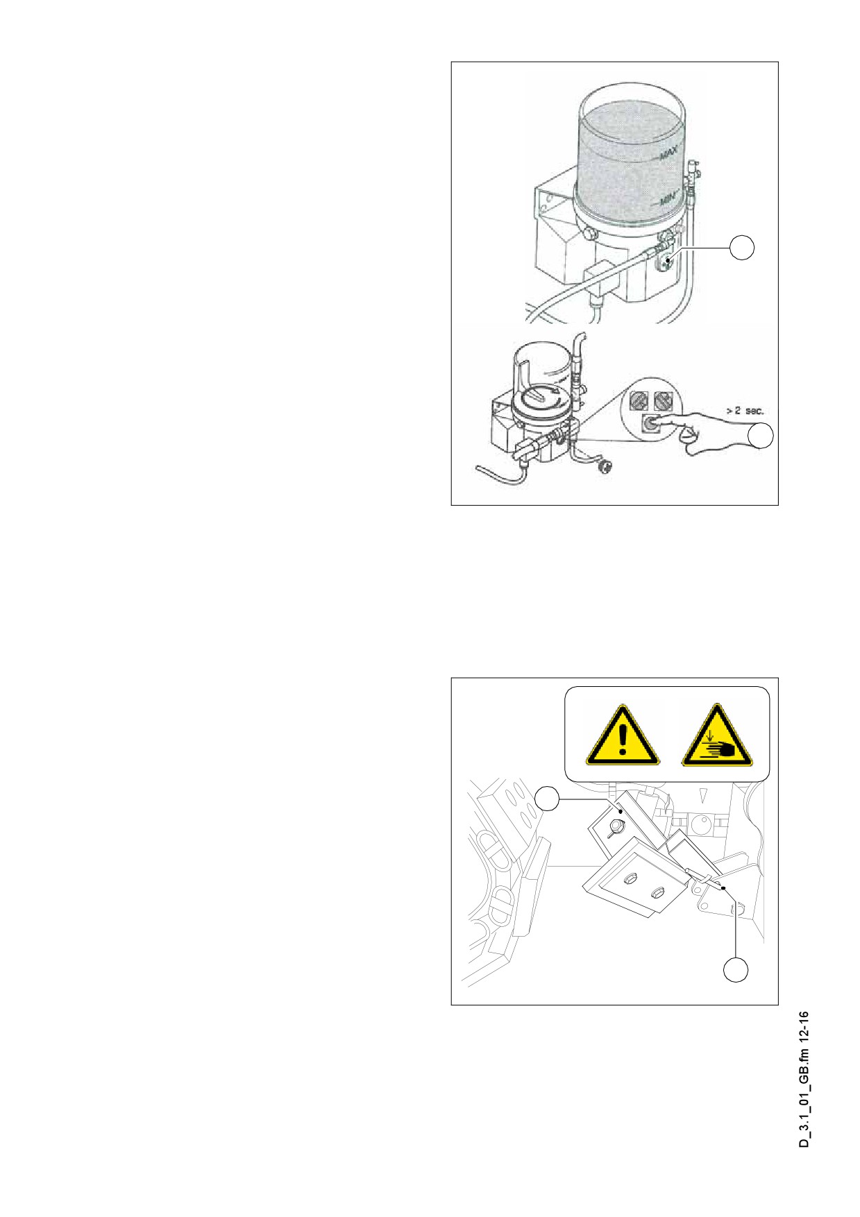
Central lubrication unit (o) (100)
The central lubrication unit turns on in
automatic mode when the drive engine
starts.
- Pumping time:
12 min
- Duration of the break:
2 h
It is prohibited to change the factory-set
a
m
durations of pumping and break without
consulting the technical customer serv-
ice!
Changing the duration of lubrication and
A
breaks may be necessary when placing
mineral or cement bound material mix.
Manual start of lubrication (pumping
b
time):
Lincoln3.jpg/Lincoln9.jpg
- Remove the cover lid (a).
- Keep the starting button (b) depressed for at least 2 sec.
- Replace the cover lid (a).
Observe the instructions of chapter „Maintenance“!
A
Track cleaner (o) (101)
Movable track cleaners (a) are fitted be-
fore the two front crawler tracks, which
divert the small obstacles to the side.
The track cleaners may be in folded
A
down position only while paving.
a
Tilting of the track cleaner:
- Remove the safety pin (b) and the bol-
ster.
- Set the track cleaner (a) to the re-
quired position and lock again with the
bolster and the safety pin.
b
Rockdeflec.eps
D 3.1 12

Particle filter - control light (102) (o)
A The control light of the particle filter is
found under the control track of the oper-
ating panel.
a
When observing the control light (a) it is
essential:
Partikellight.tif
Indicator
Operating condition
Cause / action
colour
No counterpressure Check the
yellow
No counterpressure
tightness of the system.
green
Within the measuring range
There is no fault
Treshold range -
Increase of engine speed to raise
flashing
Counterpressure in the
the temperature of the exhaust
green
warning range
fume.
Increase of engine speed to raise
Set value achieved /
the temperature of the exhaust
red
exceeded
fume. If necessary, clean / replace
the particle filter.
The temperature or pressure
Check and replace, as required,
flashing red
sensor failed
the temperature / pressure sensor
With the brief increase of the engine speed to the max. range, the filter is cleaned au-
A
tomatically due to the higher temperature of the exhaust fume.
If the control light still fails to turn on for this action, the filter needs to be cleaned.
See chapter „Maintenance“ for cleaning the particle filter.
D 3.1 13
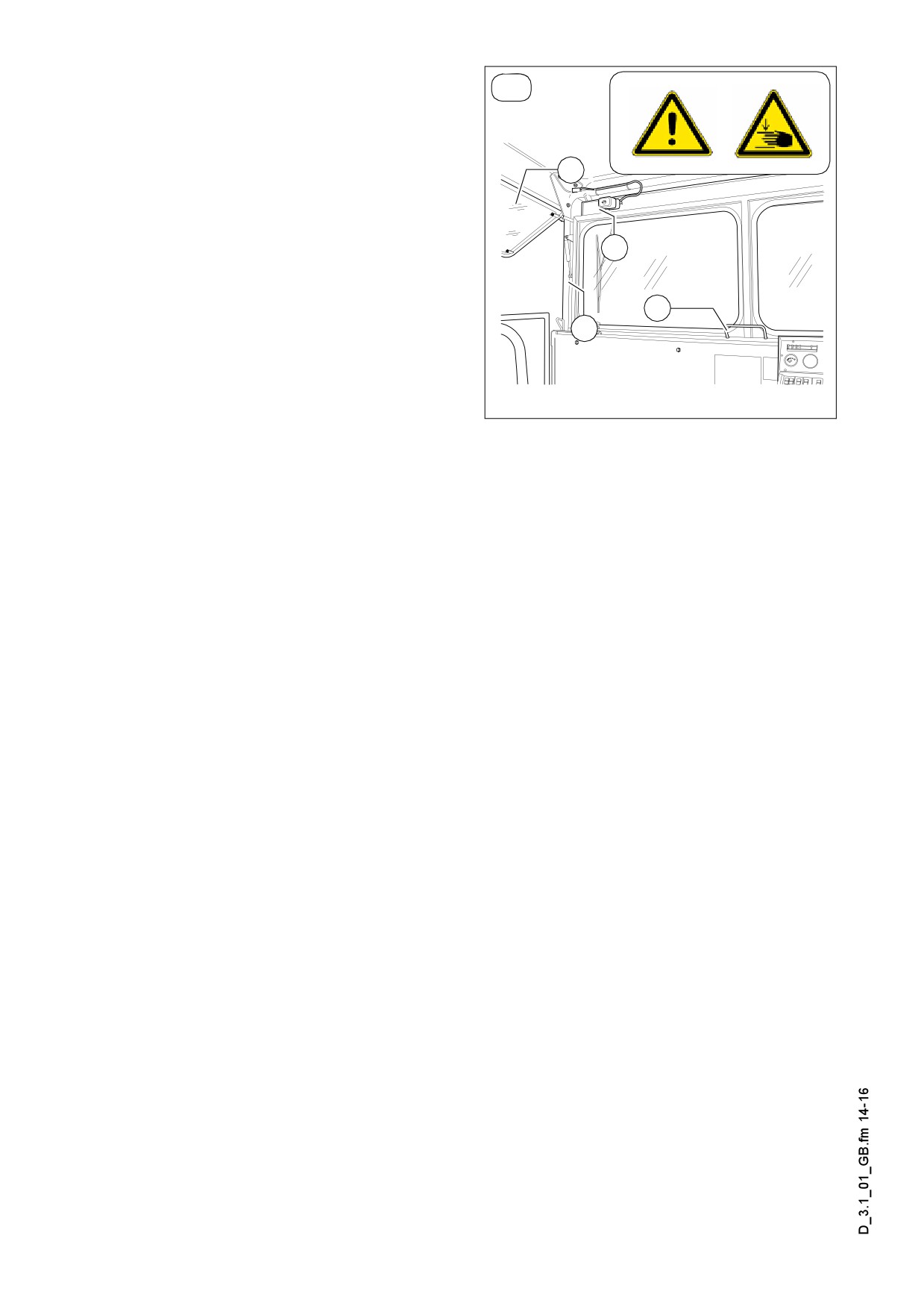
Front and side window (o) (103)
(o)
The front window can be folded up for
the maintenance works performed at the
tank.
D
- Fold the front window by its handle (A)
and lock it on the RH and LH sides
with the two locks (B) in the upper po-
C
sition.
A
Additional functions:
B
- If necessary, turn on the windscreen
wipers on the RH and LH sides (C).
- Fold up the side window (D) at its cle-
Wetterhaus.eps
vis (window frame) and the push the
driver's seat out.
D 3.1 14
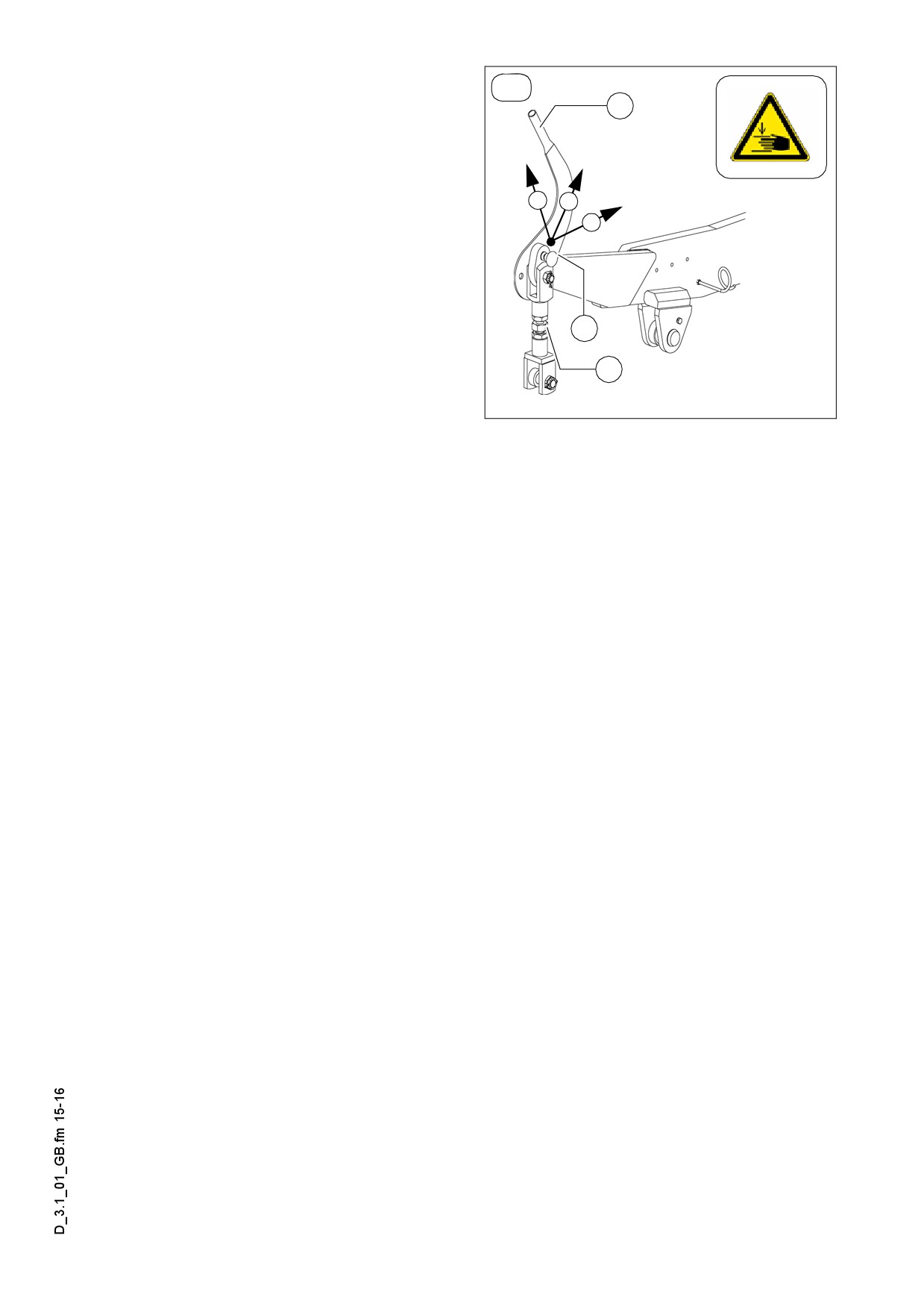
Adjustment of screed eccentric (o)
(o)
(104)
C
To pave thicker layers of material, if the
piston rods in the levelling cylinder are
operating close to their limit position and
III
II
if the desired paving thickness cannot be
I
reached, it is possible to alter the ap-
proach angle of the screen by adjusting
the eccentric.
- Pos I:
Paving thickness of up
B
to approx. 7cm
- Pos II: Paving thickness of approx.
A
7 cm to approx. 14cm
- Pos III: Paving thickness above
Wetterhaus.eps
approx. 14 cm
- The spindle (A) is not adjusted.
- Unfasten lock nuts (B) for eccentric adjustment.
- Swivel screed into desired position using lever (C) then engage the locking knob
once again.
If the levelling unit is connected to a height controller, this has the function of balanc-
A
ing out any rapid rise in the screed position: The levelling cylinders are extended until
the correct height is reached.
The change in approach angle can only take place slowly and uniformly on both sides
A
at once during paving operation, and involves the use of the eccentric adjustment.
Failing this, any rapid response in the screed could easily cause waves to appear on
the road surface.
The setting process should therefore take place before work starts!
D 3.1 15
D4.1
Operation
1
Preparation of operation
Required devices and aids
To avoid delays on site, check before starting work whether or not the following de-
vices and aids are present:
- Wheel loader for transporting heavy extendable parts
- Diesel fuel
- Engine oil and hydraulic oil, lubricants
- Separating agents (emulsion) and manual injector
- Two filled propane gas bottles
- Shovel and broom
- Scraper (spatula) for cleaning the auger and the hopper infeed area
- Parts that may become necessary for extending the auger
- Parts that may become necessary for extending the screed
- Percentage spirit level and levelling rail, 4 m long
- Levelling wire
- Protective clothing, signal vest, gloves, ear protection
Before starting work
(in the morning or when starting paving)
- Heed the safety instructions.
- Check the personal protective equipment.
- Take an inspection walk around the paver finisher and check for leaks and damag-
es.
- Install parts removed for transportation or for the night.
- When screed is operated with the optional gas heating system, open the closing
valves and the main shut-off valve.
- Perform the check according to the ”Checklist for the machine operator” given be-
low.
D4.1 1

Checklist for the machine operator
Check!
How?
Emergency stop button
Push in the button.
- on the operating panel
The diesel engine and all running drives
- on both remote control units o
must stop immediately.
The paver finisher must immediately fol-
Steering
low every steering wheel movement in a
precise manner. Check straight running.
Horn
Briefly press the horn button.
- on the operating panel
The horn must sound.
- on both remote control units o
Switch on with the ignition key, walk
Lights
around the paver finisher to check and
switch off again.
With the ignition switched on, press the
Hazard warning lights of the screed
switches for extending/retracting the
(with vario screeds)
screed parts.
The rear lights must flash.
Gas heater system (o):
Check:
- Bottle holders
- Secure seat
- Bottle valves
- Cleanliness and tightness
- Pressure reducer
- Working pressure 1.5 bar
- Hose break safety devices
- Function
- Shut-off valves
- Function
- Main shut-off valve
- Function
- Connections
- Tightness
- Indicator lamps of the switch box
- All lamps must light up when the
system is switched on
D4.1 2
Check!
How?
For larger working widths, the walkway
Auger covers
plates must be extended and the auger
tunnels must be covered.
For larger working widths, the walkway
plates must be extended.
Hinged walkway plates must be swung
Screed covers and walkways
down.
Check that the side shields, the side
plates and the covers are securely seat-
ed.
When the screed is lifted, it must be
possible to push the locking rods side-
Screed transport safeguard
ways into the recesses in the cross-
beams using the lever beneath the seat.
When the hopper is closed, it must be
possible to fold the catches over the
Hopper transport safeguard
lock studs on the two halves of the hop-
per.
Both locking bolts must be in the
Protective roof
provided bore hole.
Miscellaneous:
Check that the hoods and flaps are
- Engine hood
securely seated.
- Lateral flaps
Accessories:
- Wedges
The accessories must be in the
- Warning triangle
provided holders.
- First-aid kit
D4.1 3
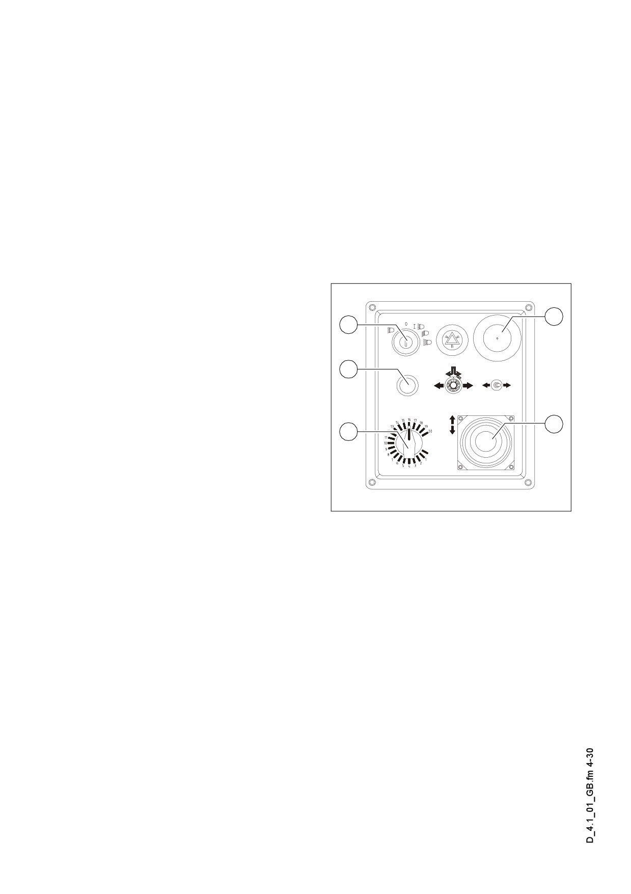
1.1
Starting the paver finisher
Before starting the paver finisher
Before starting the diesel engine and beginning operation, the following steps must
be performed:
- Daily maintenance of the paver finisher (see chapter F)
m Check the operating hour counter to determine whether or not additional mainte-
nance work (such as monthly or yearly maintenance) must be performed.
- Check the safety devices and protective devices.
„Normal” starting
Set the drive lever (9) to the center posi-
7
5
tion and the speed adjuster (10) to mini-
mum.
11
- Insert the ignition key (5) in position
„0”. The lights should be switched off
during starting to reduce the current
drain on the battery.
9
10
A It is impossible to start the machine, if
the drive lever is not in the central posi-
tion or if one of the emergency stop but-
tons (7) is depressed.
Element2_SPS_Kette_635.wmf
(“STOP“ is seen on the LC display)
- Press the starter button (11) to start the engine. Do not let the starter run perma-
nently for more than 20 seconds; allow for a break of 1 minute after every attempt.
D4.1 4
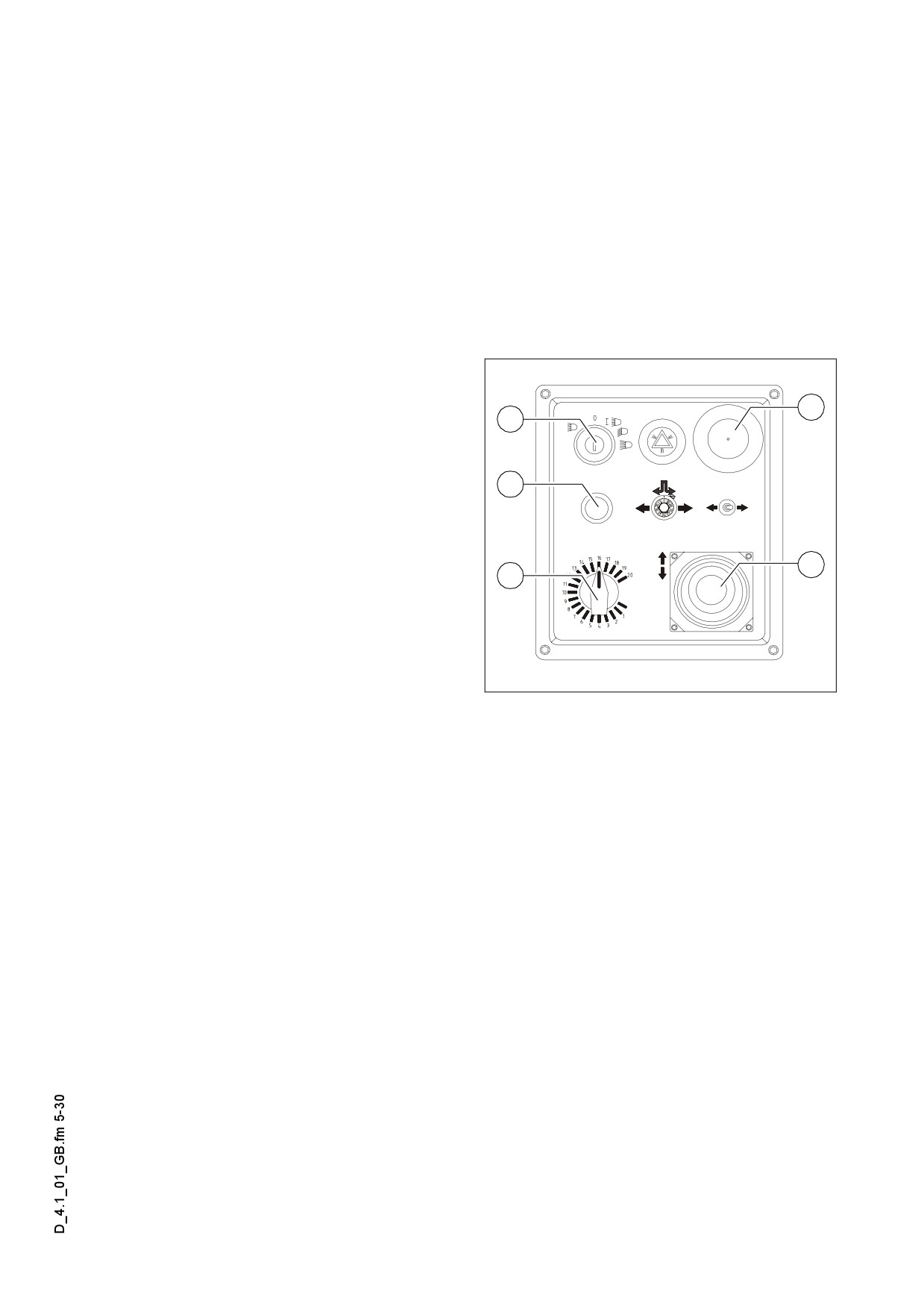
External starting (starting aid)
The engine can be started with the help of an external power source if the batteries
A
are empty and the starter no longer turns.
Suitable power sources are:
- Other vehicles with a 24 V system
- Additional 24 V battery
- Start device that is suitable for external starting (24 V/90 A).
Standard chargers or quick chargers cannot be used for external starting.
m
To externally start the engine:
- Switch on the ignition, set the drive le-
7
5
ver (9) to the center position.
- Use appropriate cables to connect the
external power source.
11
Observe the polarity! Always connect
m
the negative cable last and disconnect it
first!
9
10
It is impossible to start the machine, if
A
the drive lever is not in the central posi-
tion or if one of the emergency stop but-
tons (7) is depressed.
Element2_SPS_Kette_635.wmf
(“STOP“ is seen on the LC display)
- Press the starter button (11) to start the engine. Do not let the starter run perma-
nently for more than 20 seconds; allow for a break of 1 minute after every attempt!
When the engine is running:
- Disconnect the power source.
D4.1 5
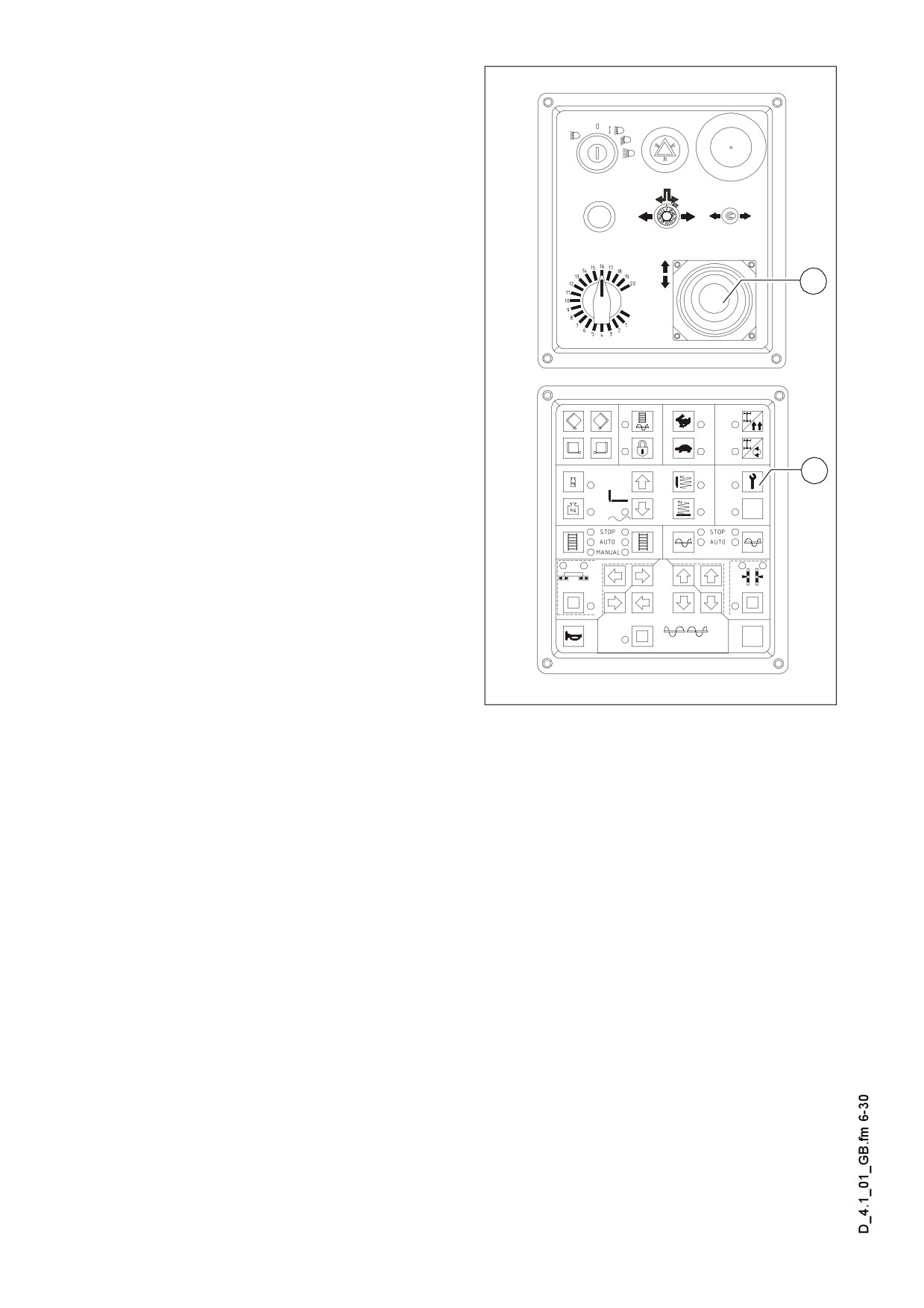
After starting
To increase the engine speed:
- Set the drive lever (9) to position 1
(slightly off the center position).
- Increase the engine speed by press-
ing button (21) on the operating panel.
The engine speed will be increased to
9
the preselected value.
m Let the paver finisher warm up for ca. 5
minutes if the engine is cold.
Indicator lamps
The following indicator lamps must be
21
observed under all circumstances:
For further possible faults, refer to the
operating instructions for the engine.
Element2_SPS_Kette_635.wmf/Element1_SPS_Kette_635.wmf
D4.1 6
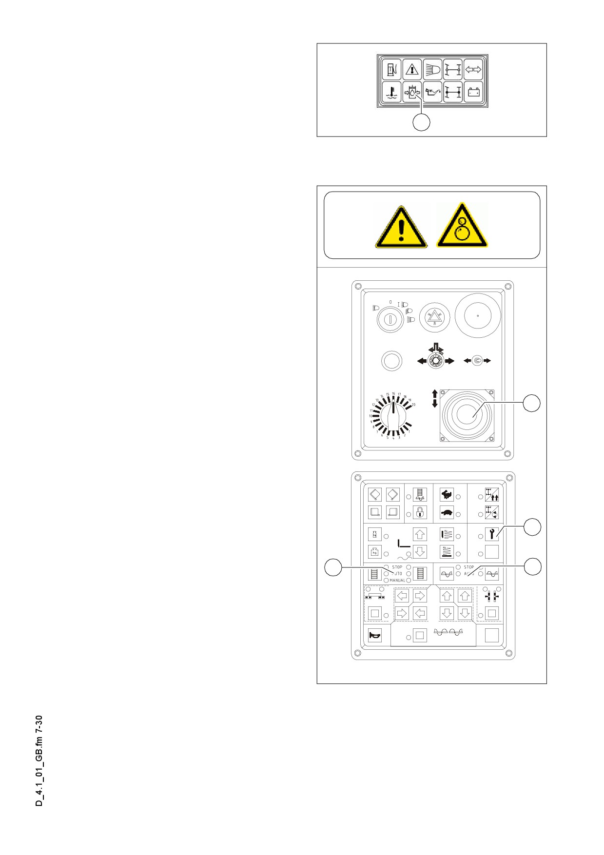
Oil pressure indicator lamp for the
traction drive (46)
- Must go out after starting.
If the lamp does not go out: Do not
m
46
switch on the traction drive! Otherwise,
Leuchtmodul_SPS_Kette_635.bmp
the entire hydraulic system could be
damaged.
When the hydraulic oil is cold:
- Set the conveyor switch (32) to „man-
ual” and the auger switch (24) to „au-
to“.
- The remote control has to be connect-
ed and the same function have to be
set to „auto“
- Set the drive lever (9) to position 1
- Press button (21) to increase the en-
gine speed, the conveyor and the au-
ger start operating.
- Let the hydraulics warm up until the in-
dicator lamp goes out.
9
The lamp goes out when the pressure
A
drops below 2.8 bar = 40 psi.
For further possible malfunctions, refer
to section 4.
21
32
21
Element2_SPS_Kette_635.wmf/Element1_SPS_Kette_635.wmf
D4.1 7

Battery charge indicator (49).
Must go out after starting when the en-
gine revs up.
49
m Briefly rev up the engine when the lamp
Leuchtmodul_SPS_Kette_635.bmp
does not go out or lights up during oper-
ation.
Switch off the engine and determine the cause for the malfunction if the lamp does
not go out.
For further possible malfunctions, refer to the section „Malfunctions”.
D4.1 8
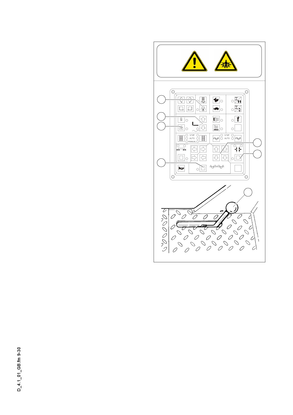
1.2
Operation in case of transportation
Lifting and securing the screed
- Button (16) has to be switched off
- Switch off the buttons (34) and lift the
screed full by using button (33).
- Extend the levelling cylinders full by
using the buttons (25) and (27).
The remote control has to be connect-
16
ed and the same function has to be set
to „manual“.
- Lift the auger crossbeam by using the
33
buttons (28) and (27).
34
- Insert the screed transport safeguards
(74).
27
25
28
74
Element1_SPS_Kette_635.wmf/F0083_A1.TIF
D4.1 9
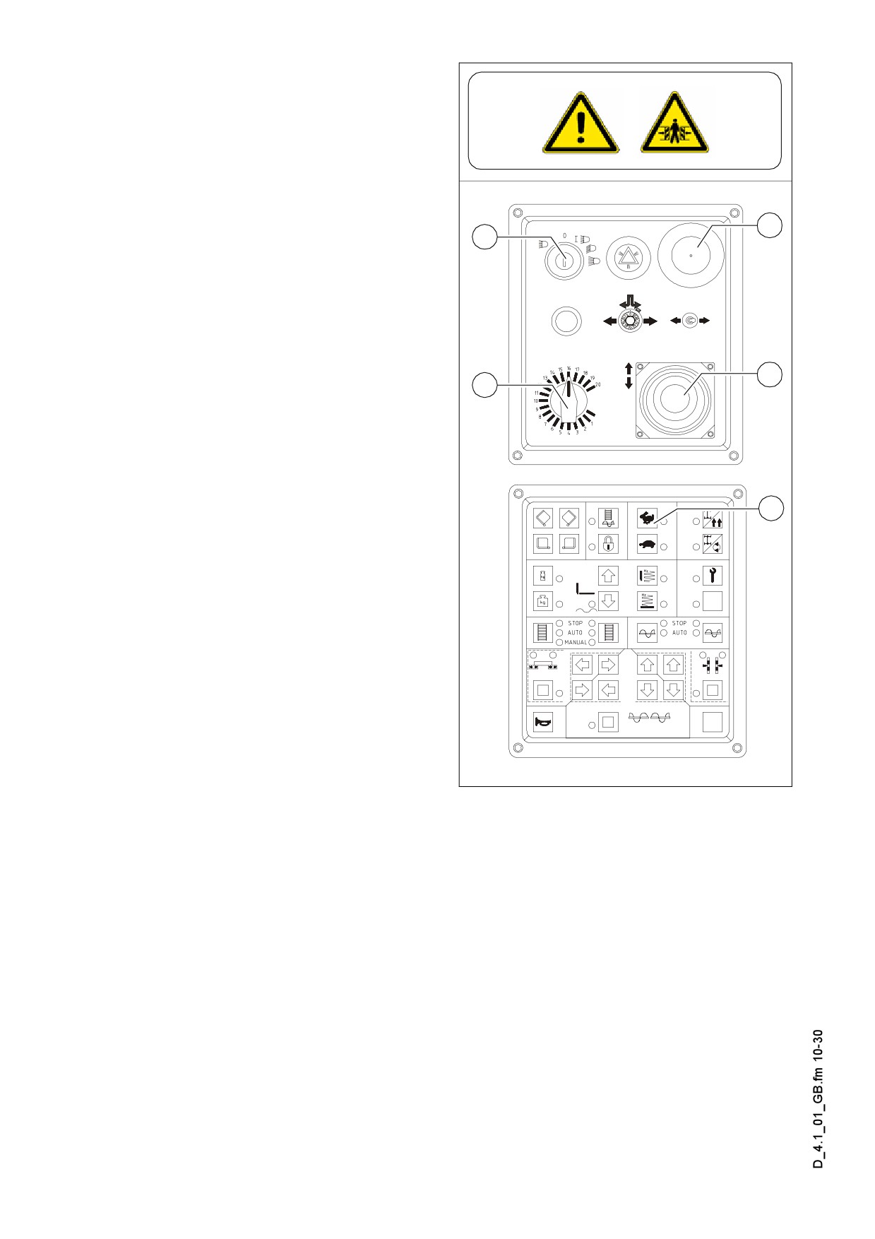
Driving and stopping the paver
finisher
- Set the Fast/Slow switch
(17) to
„Hare”.
- Set the preselector traction drive (10)
to mark 10
- For driving, carefully tilt the drive lever
7
(9) forward or backward according to
5
the drive direction desired.
f In case of an emergency, press the
emergency stop button (7)!
- To stop the paver finisher, set the
9
drive lever (9) to the center position.
10
Switching off and securing the paver
finisher
- Turn the ignition key (5) to the „0” po-
17
sition and pull it out to switch off the
engine.
m The battery can get exhausted if the pav-
er finisher is standing still for longer peri-
ods of time with the ignition switched on.
- Lower the screed.
Element2_SPS_Kette_635.wmf/Element1_SPS_Kette_635.wmf
D4.1 10

1.3
Preparations for paving
Separating agent
Spray the parts coming into contact with
asphalt
(hopper, screed, auger, push
roller) with a separator emulsion.
m Do not use diesel fuel as it dissolves the
bitumen (prohibited in Germany!).
F0147_A1.TIF
Screed heater
Switch on the screed heater ca. 15-30 minutes (depending on the ambient tempera-
ture) before paving begins. Warming up prevents the material from sticking to the
screed plates.
D4.1 11
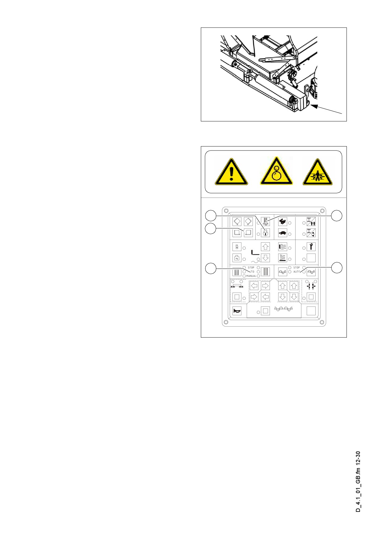
Direction marks
To ensure straight paving, a direction
mark must be present or established
(road edge, chalk lines or similar).
- Slide the operating panel to the de-
sired side and secure it.
- Pull the direction indicator out of the
bumper (arrow) and adjust it accord-
Stossstange.bmp
ingly.
Loading/distributing material
- Button (16) has to be switched off.
- Use switch (13) to open the hopper.
Instruct the truck driver to dump the
material.
- Set the switches for the auger (24) and
the conveyor (32) to „auto”.
16
15
- Press button (15) to fill the machine for
13
paving.
32
24
Element1_SPS_Kette_635.wmf/F0083_A1.TIF
D4.1 12
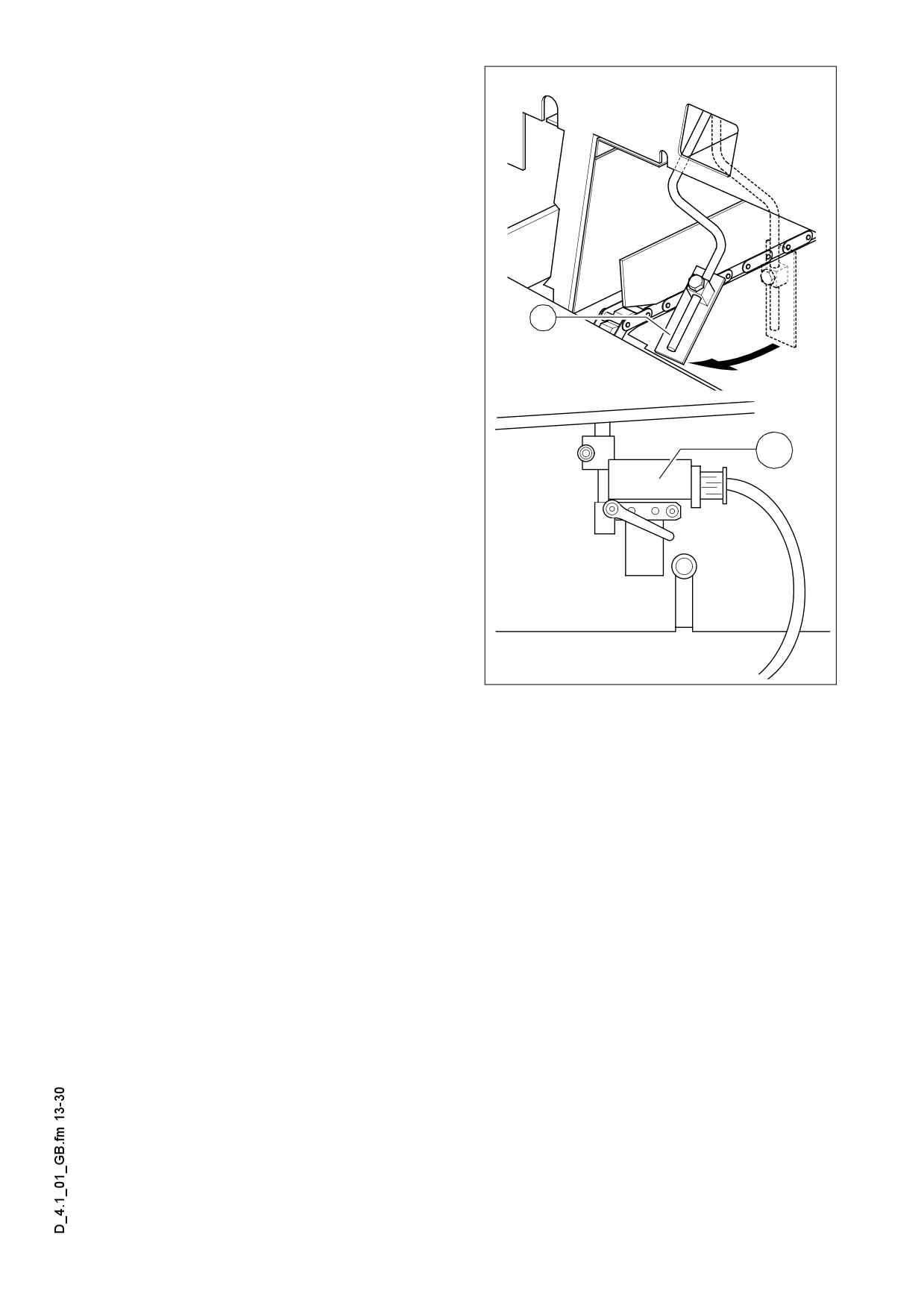
- Switch the conveyors on.
The limit switches for the conveyors
(89) or (89ao) must switch off when
the material has reached the area be-
neath the auger crossbeam.
- Check that the material is conveyed
properly.
Manually switch on or off the conveyor
if the material is not conveyed properly
until a sufficient amount of material
lies in front of the screed.
89
89a
F0114_A1.EPS/Ultra3.EPS
D4.1 13
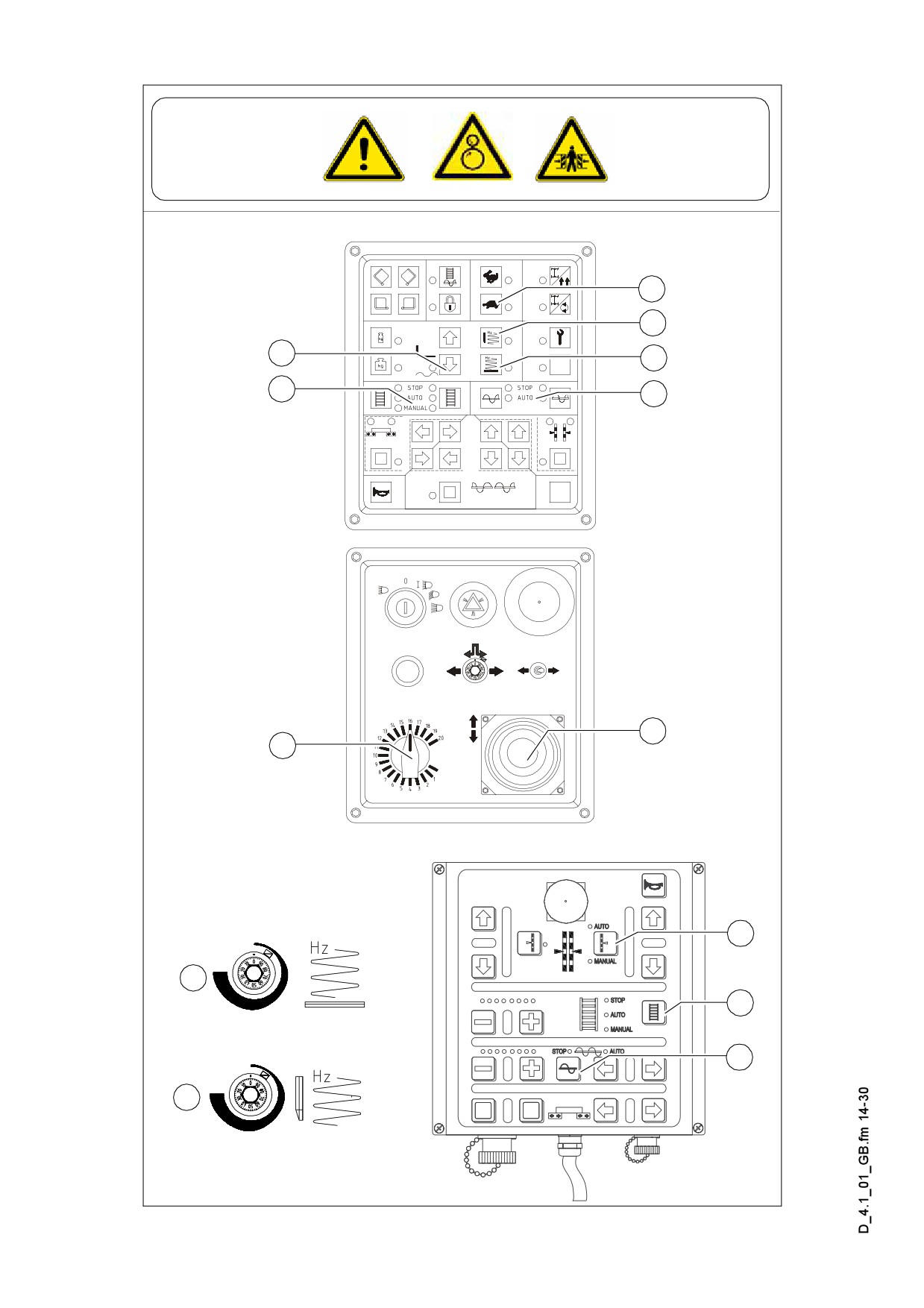
1.4
Starting for paving
17
20
33
23
32
24
9
10
51
A
54
56
B
Element2_SPS_Kette_635.wmf/Element1_SPS_Kette_635.wmfr/Tamprev.cdr/Vibrev.cdr/Remote_SPS_neu1cdr
D4.1 14

Set the switches, levers and controls listed below to the specified positions when the
screed has reached its operating temperature and a sufficient amount of material lies
in front of the screed:
Item
Switch
Position
17
Traction drive fast/slow
Tortoise-operating speed
10
Preselector traction drive
Mark 6-7
Preparation for screed floating
33
LED ON
position
23
Vibration
LED ON
20o
Tamper
LED ON
24/56
Auger left/right
Auto
32/54
Conveyor left/right
Auto
51
Levelling
Auto
A
Speed regulator, vibration
ca. mark 40-60
B
Speed regulator, tamper
ca. mark 40-60
- Push the drive lever (9) all the way to the front and start driving.Screed floating po-
sition is activated now.
- Observe the distribution of the material and adjust the limit switches if necessary.
- Set the compacting elements (tamper and/or vibration) according to the required
compaction ratio.
- Let the paving master check the layer thickness after 5-6 meters and correct if nec-
essary.
Carry out the check in the area of the drive chains or wheels as the screed tends to
level an uneven ground. The reference points for the layer thickness are the drive
chains or wheels.
The basic setting of the screed must be corrected when the actual layer thickness de-
viates significantly from the values indicated by the scales (see the operating instruc-
tions for the screed).
The basic setting is for asphalt material.
A
D4.1 15
1.5
Checks during paving
The following points must be constantly observed during paving:
paver finisher function
- Screed heater
- Tamper and vibration
- Engine oil and hydraulic oil temperature
- The screed parts must be retracted and extended in time when obstacles are in the
way
- Uniform material transport and distribution or supply to the screed; may require cor-
rections to settings of the material switches for conveyor and auger.
See the section ”Malfunctions” when paver finisher functions fail.
A
Quality of the layer
- Layer thickness
- Slope
- Evenness in the driving direction and at right angles to it (check with 4 m levelling
rod)
- Surface structure/texture behind the screed.
See section 4 ”Malfunctions, Problems during Paving” if the paving quality is poor.
A
1.6
Paving with screed stop and screed charging/relieving
General
The screed hydraulics can be influenced in two ways to attain optimum paving re-
sults:
- Screed stop with and without pretensioning with the paver finisher halted,
- Screed charging or relieving with the paver finisher driving.
A Relieving reduces the screed weight and increases the traction force.
Charging increases the screed weight, reduces the traction force, but increases the
compaction ratio. (To be used with light-weight screeds in exceptional cases.)
D4.1 16

Screed charging/relieving
This function charges or relieves the screed regardless of its own dead weight.
Switch (34) has the following positions:
A
A: Relieving (screed ‘lighter’)
34
B: Charging (screed ‘heavier’)
B
Switch positions
„Screed charging/re-
lieving” are only effective when the pav-
Screedswitch2a.bmp
er finisher moves. When the paver
finisher stops, „screed stop” is automati-
cally selected.
D4.1 17

Screed stop with prestressing
When „stopping the screed“ the relieving
pressure and the counterpressure of the
A
A
material will provide retention so that the
34
33
sinking of the screed is avoided when a
temporary stop occurs.
B
B
- Automatic screed stop when the drive
Screedswitch2a.bmp
lever is in the center position
- To lift the screed press button (33A).
- Lowering of the screed:
- Resting function: Keep the button (33B) depressed for more than 1.5 sec. As long
as you keep the button depressed, the screed will be lowered. When the button
is released, the screed will stop again.
- Button function: Press button (33B) briefly - the screed will lower again. Press the
button briefly again - the screed will stop.
In case of transportation or maintenance operations always insert the mechanical
m
transportation safeguard of the screed.
As for charging/relieving, a pressure of 2-50 bar can be individually applied to the
screed lifting cylinders. This pressure can neutralize the weight of the screed to pre-
vent the screed from sinking into the freshly laid material, thus supporting the screed
stop function, especially in those situation where the screed relieving function is used.
The pressure to be applied depends on the load-bearing capacity of the material. If
necessary, the pressure must be readjusted or changed as required during the first
stops until the lower edge of the screed no longer leaves any marks when the paver
finisher moves on again.
A pressure greater than 10-15 bar neutralizes the screed weight, thus preventing the
screed from sinking into the material.
When combining the ”screed stop” and ”screed relieving” functions, make sure that
A
the pressure difference between the two functions does not exceed 10-15 bar.
Especially in those cases where the ”screed relieving” function is only briefly used as
a start-up aid, there is a danger of uncontrolled floating when starting up again.
D4.1 18
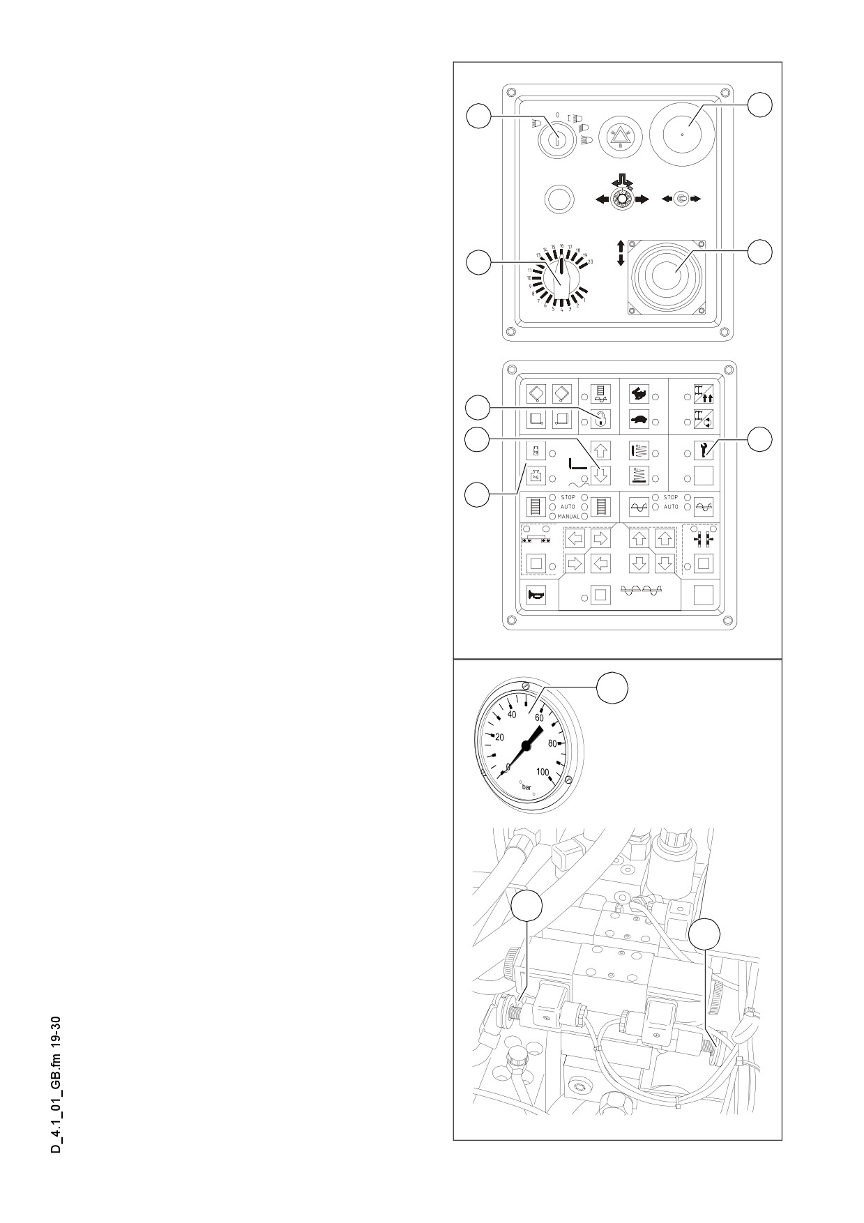
Adjusting the pressure (o)
7
Pressure adjustments can only be made
5
while the diesel engine is running.
Therefore:
- Start the diesel engine and set the
traction controller (10) to zero (precau-
tion against inadvertent advancing).
- Set switch (33) to the floating position.
9
10
Screed stop (with prestressing):
- Set the drive lever (9) to the center po-
sition.
- Set switch (16) to position (LED OFF)
16
and switch (21) to position (LED OFF).
33
21
- Use control valve
(93a)
(below the
bottom plate of the operator´s plat-
form) to adjust the pressure and read
34
it from the pressure gauge (93c).
(Basic setting: 20 bar)
Element2_SPS_Kette_635.wmf/Element1_SPS_Kette_635.wmf
For screed charging/relieving:
93c
- Set the drive lever (9) to the center po-
sition.
- Set switch (16) to position (LED OFF)
and switch (21) to position (LED ON).
- Set switch (34) to position (LED ON)
(relieving 34a) or (charging 34b).
- Set the pressure with the regulator
valve (93b) (under the bottom plate of
the operating position), and read it on
the pressure gauge (93c).
93b
When screed charging/relieving is nec-
93a
A
essary and automatic levelling is used
(grade control and/or slope control), the
compacting performance changes (layer
thickness)
The pressure can also be set or correct-
A
ed during paving. (max. 50 bar)
F0103_A1.EPS/Screedvalve.eps
D4.1 19
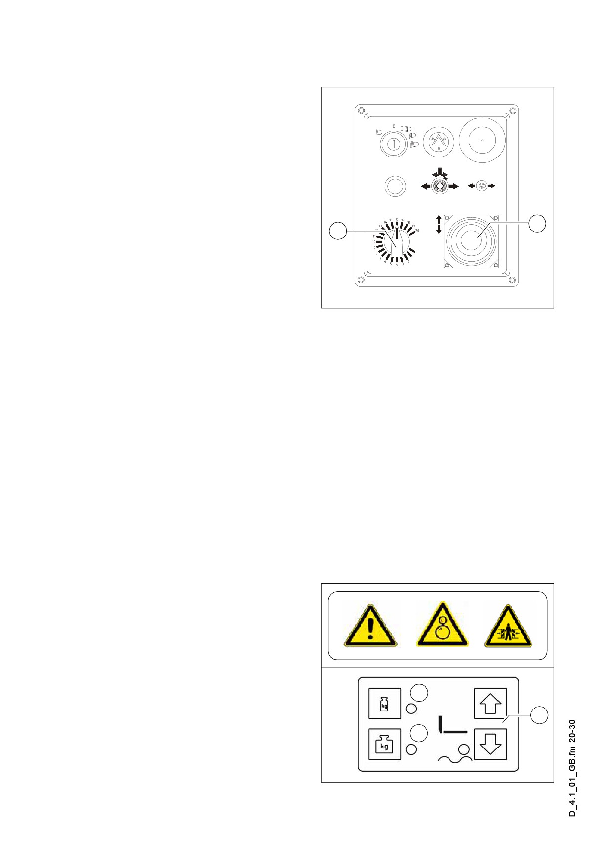
1.7
Interrupting/terminating operation
During breaks: (e.g. the material supply
truck is late)
- Determine the approximate duration.
- When cooling down of the material be-
low the minimum paving temperature
must be expected, run the paver fin-
isher empty and create an edge like
the end of a layer.
- Set the drive lever (9) to the center po-
9
10
sition.
Element2_SPS_Kette_635.wmf
During extended interruptions (e.g. lunch break)
- Drive lever (9) into centre position, RPM speed adjustment (10) to minimum posi-
tion.
- Switch off ignition.
- Switch off screed heater (system).
- When screed is operated with the optional gas heating system, close the valves of
the bottles.
A The screed must be heated up to the correct paving temperature before paving may
be restarted.
When work is finished
- Run the paver finisher empty and stop
it.
- Lift the screed by using button (33).
- Retract the screed parts to the basic
screed width and lift the auger. Where
applicable, completely extend the lev-
elling cylinders.
A
33
B
Screedswitch2a.bmp
D4.1 20
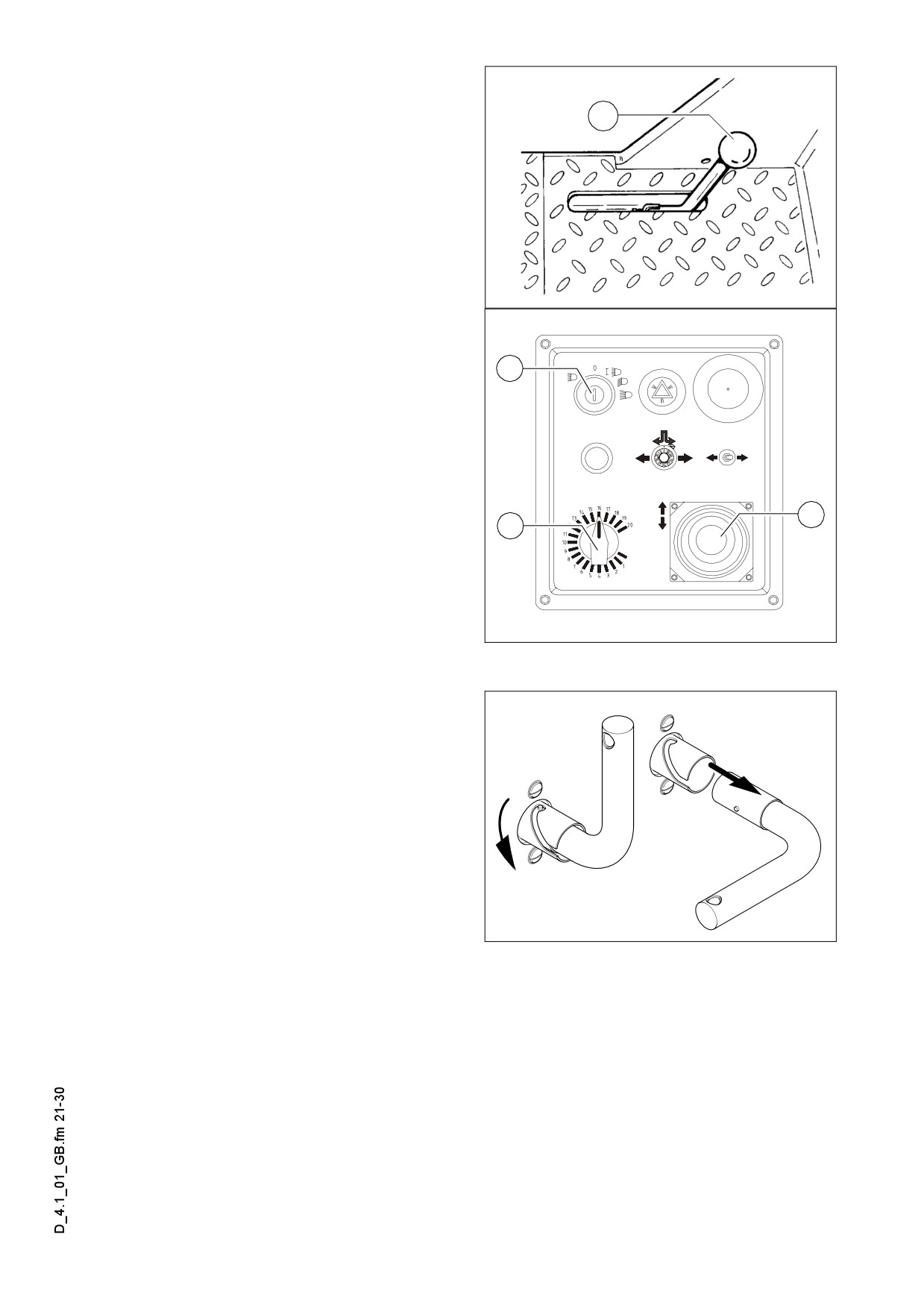
- Insert the mechanic screed transport
safeguard (74) on both screed lifting
cylinders.
74
- While operating the tampers at a low
speed, let any material residues drop
out.
F0083_A1.Tif
- Set the drive lever (9) to the center po-
sition and the speed adjuster (10) to
minimum
5
- Switch off the ignition (5).
- Switch off screed heater (system).
- When screed is operated with the op-
tional gas heating system, close the
main shut-off valves and the valves of
the bottles.
9
- Remove the levelling units and stow
10
them away in the boxes, close all flaps
- Remove all parts that extend beyond
the paver finisher contour or secure
them if the paver finisher is to be trans-
Element2_SPS_Kette_635.wmf
ported over public roads on a low-bed
trailer.
Do not turn off main switch until 15 sec-
m
onds after the ignition has been turned
off!
The engine electronics need this length
A
of time to back up data.
F0077/0078_A1.EPS
D4.1 21
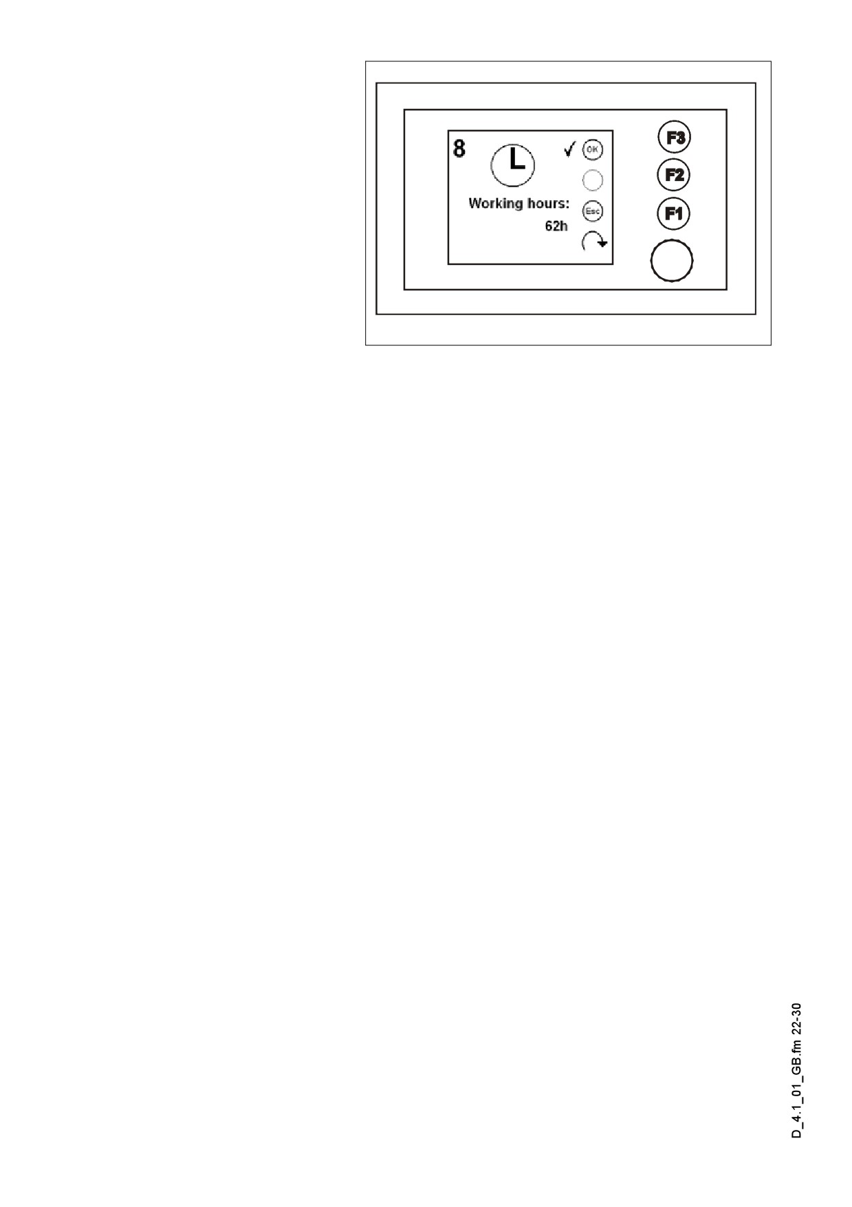
- Read and check the oper-
ating hour meter to deter-
mine whether maintenance
work must be performed
(see chapter F).
- Cover and lock the operat-
ing panel.
- Remove material residues
from the screed and the
paver finisher and spray all
parts with separator fluid.
Terminal_SPS_Kette_635.wmf/Bild_008.bmp
D4.1 22