DYNAPAC Paver finisher F 121 C, F 141 C Type 635. Operation & Maintenance (Order number: 4812026925) - page 2
7
EN standards
7.1
Continuous sound level F121C, Deutz TCD 2012L06
The operator always must use ear protection. The emission value at the ear of the
m
driver varies depending on the materials used for paving and may even rise above
85 dB (A). If no ear protection devices are used, hearing can be impaired.
The noise emission level of the finisher has been measured under free-field condi-
tions according to prEN 500-6, dated March, 1997, and ISO 4872 at a normal engine
speed of 2100 rpm.
Sound pressure level at the operator’s position
(at the height of the head):
LAF =
83,7
dB(A)
Sound capacity level:
LWA = 108,0
dB(A)
Sound pressure level at the machine
Measuring point
2
4
6
8
10
12
Sound pressure level LAFeq (dB(A))
74,9
73,1
72,5
74,7
71,4
72,8
7.2
Operating conditions during measurement
The diesel engine was running at maximum speed. The screed was in working posi-
tion, lowered to a rubber mat. The tamper and the vibrator were running at min. 50%
of their maximum speed, the augers at min. 40% and the conveyors at min. 10% of
their maximum speed.
7.3
Measuring point configuration
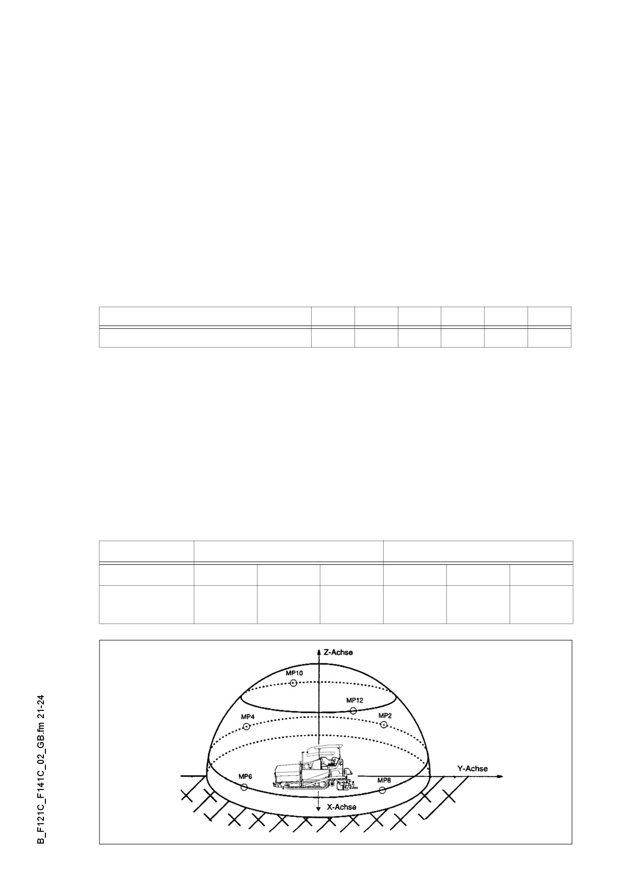
Semispherical measuring surface with a radius of 16 m. The machine was at the cent-
er. The measuring points had been assigned the following coordinates:
Measuring points 2, 4, 6, 8
Measuring points 10, 12
Coordinates
X
Y
Z
X
Y
Z
- 4,32
+10,4
11,36
±11,2
±11,2
1,5
+4,32
-10,4
11,36
SCHALL.TIF
B 21
7.4
Continuous sound level F141C, Deutz TCD 2013L06
The operator always must use ear protection. The emission value at the ear of the
m
driver varies depending on the materials used for paving and may even rise above
85 dB (A). If no ear protection devices are used, hearing can be impaired.
The noise emission level of the finisher has been measured under free-field condi-
tions according to prEN 500-6, dated March, 1997, and ISO 4872 at a normal engine
speed of 2100 rpm.
Sound pressure level at the operator’s position
(at the height of the head):
LAF =
84,4
dB(A)
Sound capacity level:
LWA = 109,0
dB(A)
Sound pressure level at the machine
Measuring point
2
4
6
8
10
12
Sound pressure level LAFeq (dB(A))
75,3
74,2
73,3
75,8
73,5
74,8
7.5
Operating conditions during measurement
The diesel engine was running at maximum speed. The screed was in working posi-
tion, lowered to a rubber mat. The tamper and the vibrator were running at min. 50%
of their maximum speed, the augers at min. 40% and the conveyors at min. 10% of
their maximum speed.
7.6
Measuring point configuration
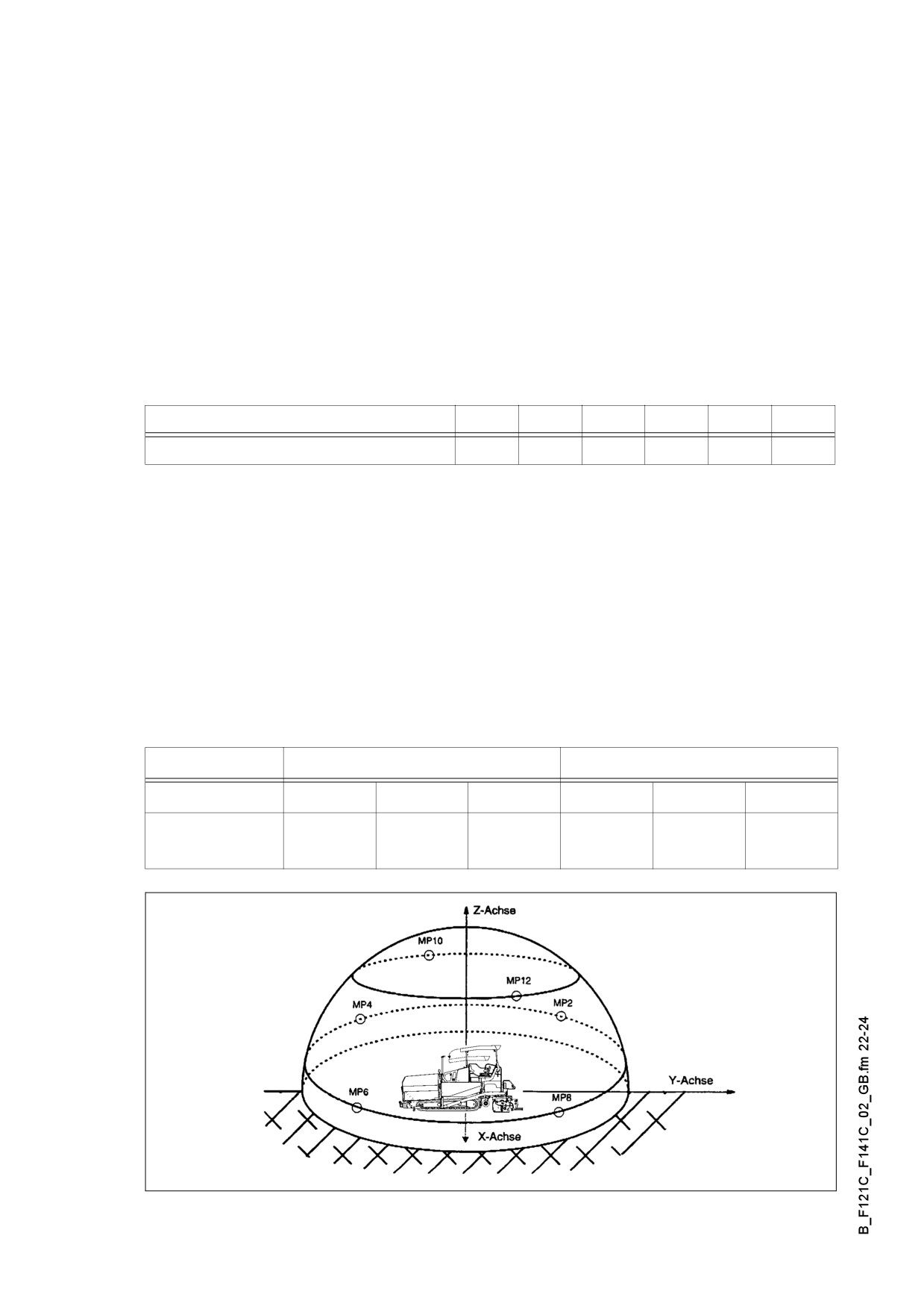
Semispherical measuring surface with a radius of 16 m. The machine was at the cent-
er. The measuring points had been assigned the following coordinates:
Measuring points 2, 4, 6, 8
Measuring points 10, 12
Coordinates
X
Y
Z
X
Y
Z
- 4,32
+10,4
11,36
±11,2
±11,2
1,5
+4,32
-10,4
11,36
SCHALL.TIF
B 22
7.7
Vibration acting on the entire body
When the machine is used properly, the weighted effective acceleration values at the
driver’s seat of aw = 0.5 m/s2 according to prEN 1032-1995 are not exceeded.
7.8
Vibrations acting on hands and arms
When the machine is used properly, the weighted effective acceleration values at the
driver’s seat of ahw = 2.5 m/s2 according to prEN 1033-1995 are not exceeded.
7.9
Electromagnetic compatibility (EMC)
The following limit values are observed according to the stipulations of the EMC di-
rective 89/336/EEC/08.95:
- Interference emission according to DIN EN 50081-1/03.93:
< 40 dB µV/m for frequencies of 30 MHz - 230 MHz measured at a distance of 3 m
< 47 db µV/m for frequencies of 20 MHz - 1 GHz measured at a distance of 3 m
- Interference immunity against electrostatic discharge according to DIN EN 61000-
4-2/03.96 (ESD):
The paver finisher did not show any discernible reactions to contact discharges of
± 4 KV and to air discharges of ± 8 KV.
The modifications according to test criterion „A“ are being met, i.e. the paver finish-
er continues to work without malfunction during the test.
Electrical or electronic components and their arrangement may only be modified after
A
written approval by the manufacturer has been obtained.
B 23
C 1.1
Transportation
1
Safety regulations for transportation
Accidents can happen when the paver finisher and the screed are not properly pre-
m
pared for transportation or when transportation is carried out improperly!
Reduce both the paver finisher and the screed to their basic widths. Remove all pro-
truding parts (such as the levelling device, auger limit switches, aprons, etc.). When
transporting under a special permit, secure these parts!
Close the hopper lids and engage the hopper transport safeguards. Lift the screed
and engage the screed transport safeguards. Convert the protective roof and engage
the latch.
Check that the clamping device for the auger frame is fastened and that the telescopic
tube cannot slide out (see chapter E, section 2.5).
Pack all parts that are not permanently fixed to the paver finisher and the screed into
the appropriate boxes and into the hopper.
Close all coverings and check that they are securely seated.
In Germany, gas bottles must not be transported on the paver finisher or on the
screed.
Disconnect the gas bottles from the gas system and protect them with their caps. Use
a separate vehicle to transport them.
When loading via ramps, the paver finisher may slip aside, tilt or topple over.
Drive carefully! Keep the danger area free of persons!
Additional stipulations for transportation on public roads:
In Germany; caterpillar pavers must not be driven as self-propelling vehicles on
m
public roads.
Note that in other countries different regulations may apply.
The operator must be in the possession of a valid permit for vehicles of this type.
The operating panel must be moved to the side of the oncoming traffic and secured
in this position.
The driving lights must be properly adjusted.
Only attachments and accessories may be transported in the hopper, no material or
gas bottles!
If necessary, the operator must be assisted by a second person when driving on pub-
lic roads - especially at road crossings and junctions.
C 1.1 1
2
Transportation on low-bed trailers
m Reduce the paver finisher and the screed to their basic widths; also remove any at-
tached side plates.
The maximum drive-on angle is included in Chapter „Technical Specifications“!
2.1
Preparations
- Prepare the paver finisher for transportation (see chapter D).
- Remove all protruding or loose parts from the paver finisher and the screed (see
also the operating instructions of the screed). Store these parts in a safe place.
f When screed is operated with the optional gas heating
system:
- Remove the gas bottles of the screed heating system:
- Close the main shut-off valves and the bottle valves.
- Unscrew the valves on the bottles and remove the
gas bottles from the screed.
- Transport the gas bottles on a second vehicle; heed all pertaining safety regula-
tions.
C 1.1 2
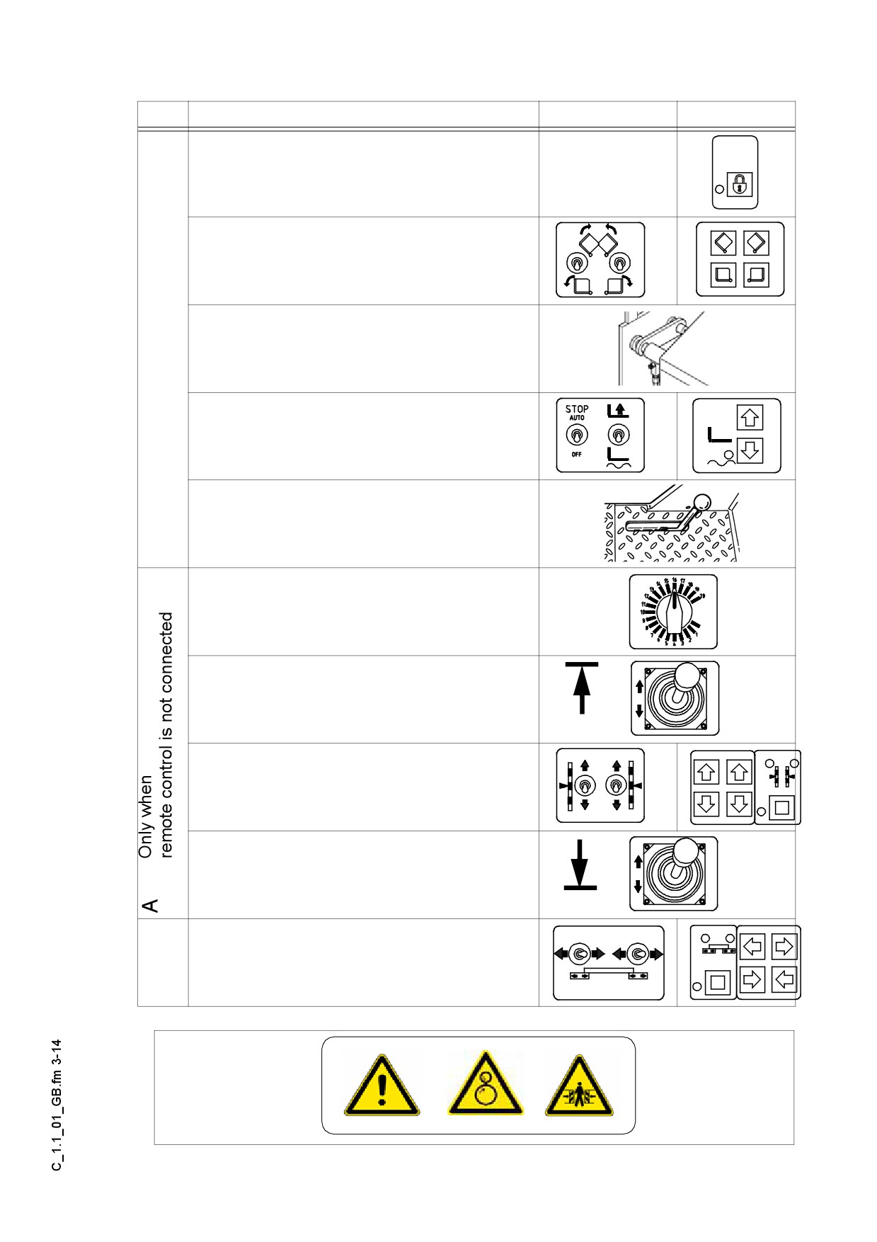
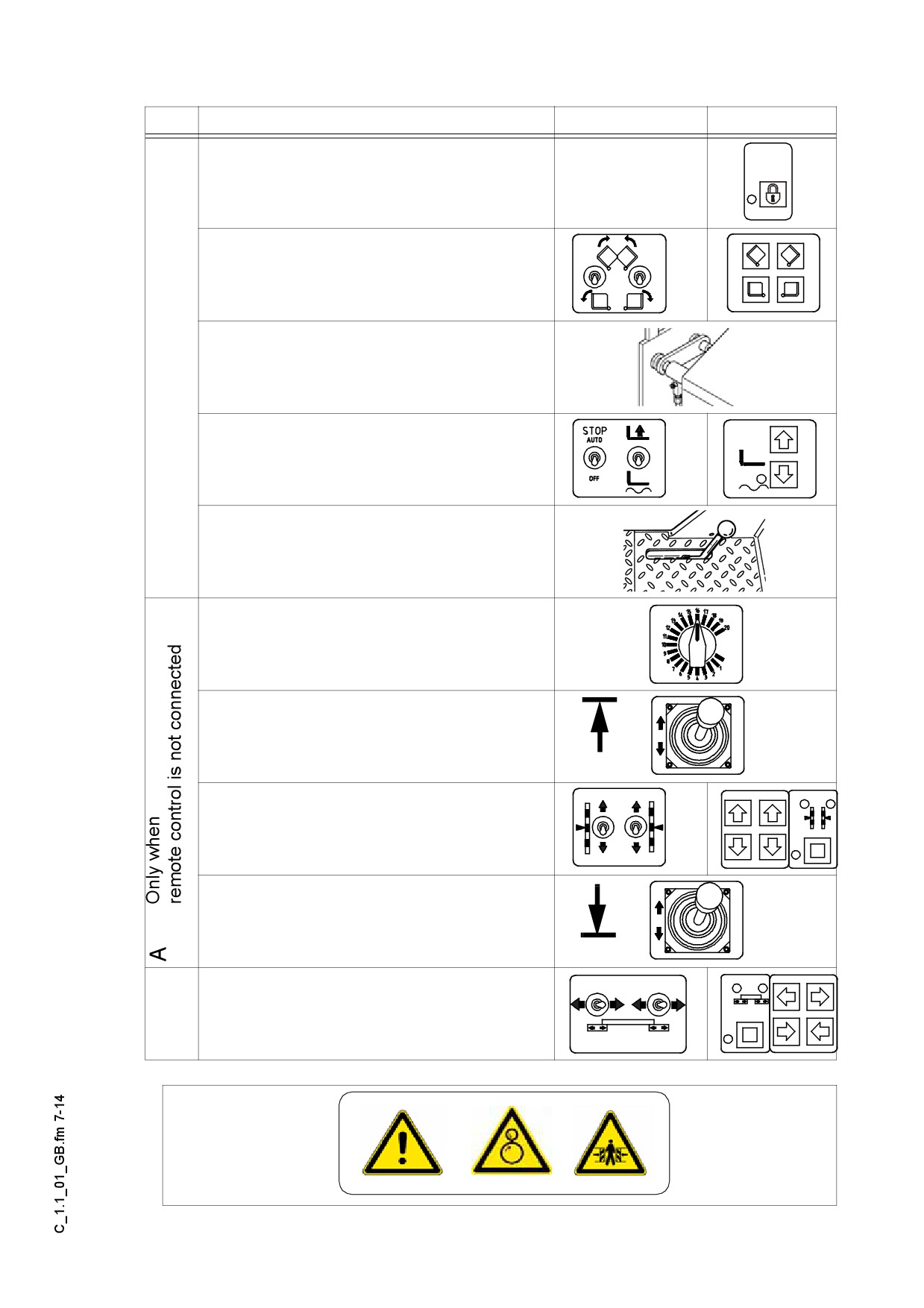
Operation
Switch
Buttons
- Disabling the interlocking of operation
- Close the hopper halves.
- Engage both hopper transport safe-
guards.
- Lift the screed.
- Insert the transportation safeguards of
the screed.
- Turn the preselecting regulator to zero.
- Move the drive lever forward.
- The levelling cylinder are in fully extend-
ed position.
- Set the drive lever to mid-position.
- Retract the screed to the basic width of
the paver finisher.
C 1.1 3
2.2
Driving onto the low-bed trailer
f Make sure that there are no persons in the danger area during loading.
A
1
2
(
)
3
F0185_A1.TIF
- Use the work gear and low engine speed to drive onto the low-bed trailer.
- Lower the screed onto wooden blocks on the low-bed trailer.
- Switch off the paver finisher.
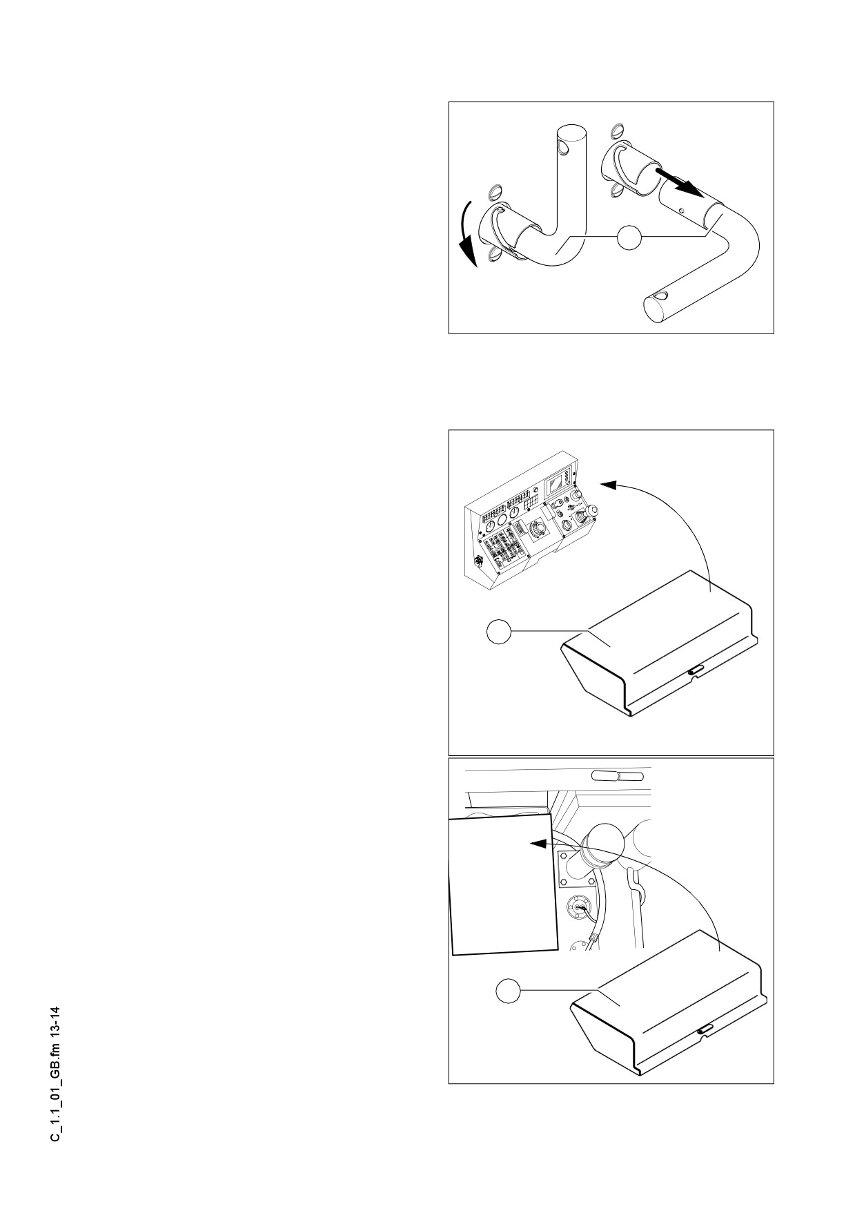
- Attach and secure the protective hood to protect the operating panel.
- If necessary, swing down the protec-
tive roof:
- Take out the bolts and pull the roof to
the rear by gripping it with the bow-
type handle. When it is in the lower po-
sition, secure it with the bolts.
Roof.tif
C 1.1 4
2.3
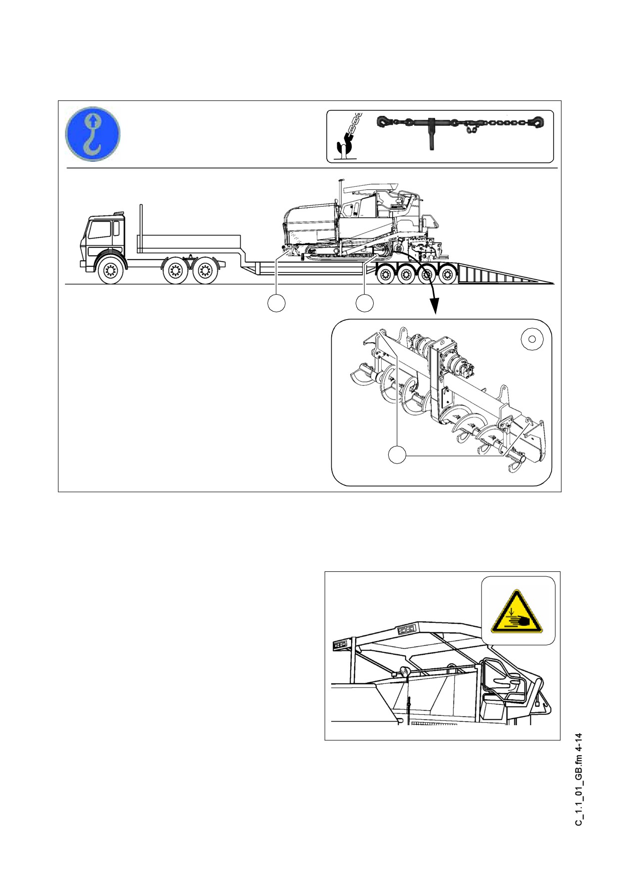
Secure the paver finisher in its position to the low-bed trailer:
- Use only proper and permitted load fastening devices.
- Use the four securing points provided (1, 2).
A Depending on the equipment of the machine there can be further support points (3)
on the auger frame (3).
- Wait until the exhaust extension pipe has cooled down; then remove it and store it.
2.4
After transportation
- Remove the attachment devices.
- Swing up the protective roof: take out the bolts, push the protective roof forward to
raise it and insert the bolts to lock it again.
- Mount the protective tarpaulin if it has been removed.
- Lift the screed to the transportation position and lock it.
- Start the engine and drive from the trailer at a low engine/traction speed.
- Park the paver finisher in a secure spot, lower the screed and switch off the engine.
- Remove the key and/or cover the operating panel with the protective hood and se-
cure it.
C 1.1 5
3
Transportation
m Reduce the paver finisher and the screed to their basic widths; also remove any at-
tached side plates.
3.1
Preparations
- Prepare the paver finisher for transportation (see chapter D).
- Remove all protruding or loose parts from the paver finisher and the screed (see
also the operating instructions of the screed). Store these parts in a safe place.
f When screed is operated with the optional gas heating
system:
- Remove the gas bottles of the screed heating system:
- Close the main shut-off valves and the bottle valves.
- Turn off the valves on the bottles and remove the gas
bottles from the screed.
- Transport the gas bottles on a second vehicle; heed all pertaining safety regula-
tions.
C 1.1 6
Operation
Switch
Buttons
- Disabling the interlocking of operation
- Close the hopper halves.
- Engage both hopper transport safe-
guards.
- Lift the screed.
- Insert the transportation safeguards of
the screed.
- Turn the preselecting regulator to zero.
- Move the drive lever forward.
- The levelling cylinder are
in fully extended position.
- Set the drive lever to mid-position.
- Retract the screed to the basic width of
the paver finisher.
C 1.1 7
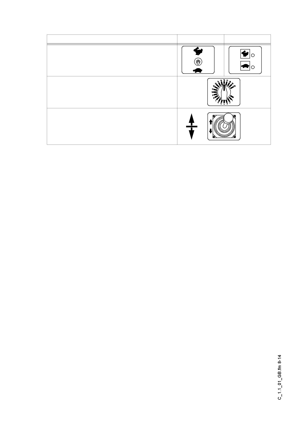
3.2
Traction drive:
Warning
Marking
Marking
- Set the Fast/Slow switch to „Hare“.
- Turn the preselecting regulator to maximum.
- Use the drive lever to regulate the speed.
f Press the emergency stop button when a dangerous situation arises!
C 1.1 8
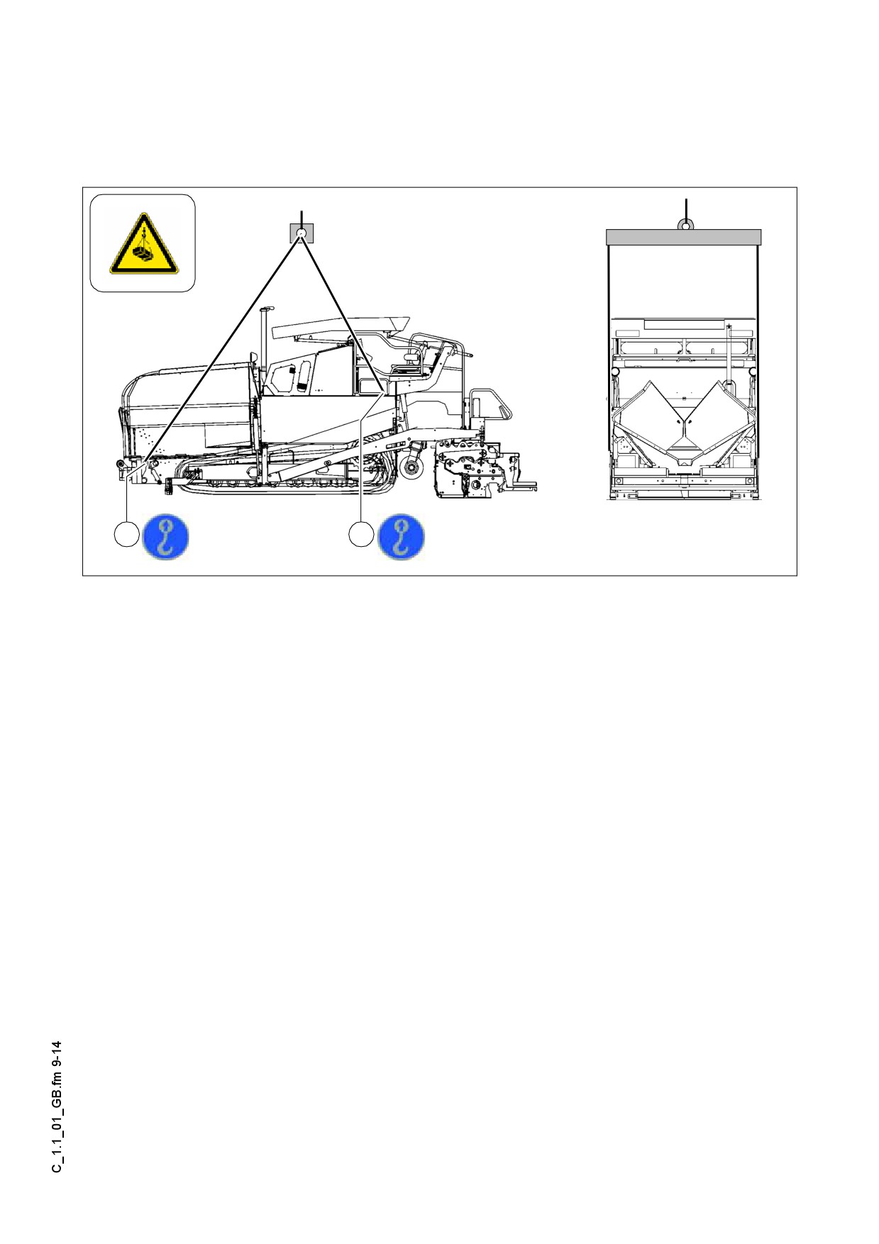
4
Loading by crane
m Use only lifting gear that can bear the load.
(See Chapter B for weights and dimensions).
1
2
F0185_A1.TIF
A Four lifting eyes (1,2) are provided for loading the vehicle with a crane.
- Park the paver finisher and render it safe.
- Engage the transport safeguards.
- Remove any attachments and accessories from the paver finisher and the screed
until the basic width has been attained.
- Take off all protruding or loose parts and the gas bottles of the screed heating sys-
tem (see Chapters E and D).
- Swing down the protective roof.
- Attach the lifting gear to the four lifting eyes (1,2).
m Make sure that the paver finisher remains in a horizontal position during transport!
C 1.1 9
5
Towing
Heed all regulations and apply all safety measures applicable for towing heavy con-
f
struction machines.
The towing vehicle must be capable of securing the paver finisher, even on slopes.
m
Use only approved tow bars!
If necessary, remove any attachments and accessories from the paver finisher and
the screed until the basic width has been attained.
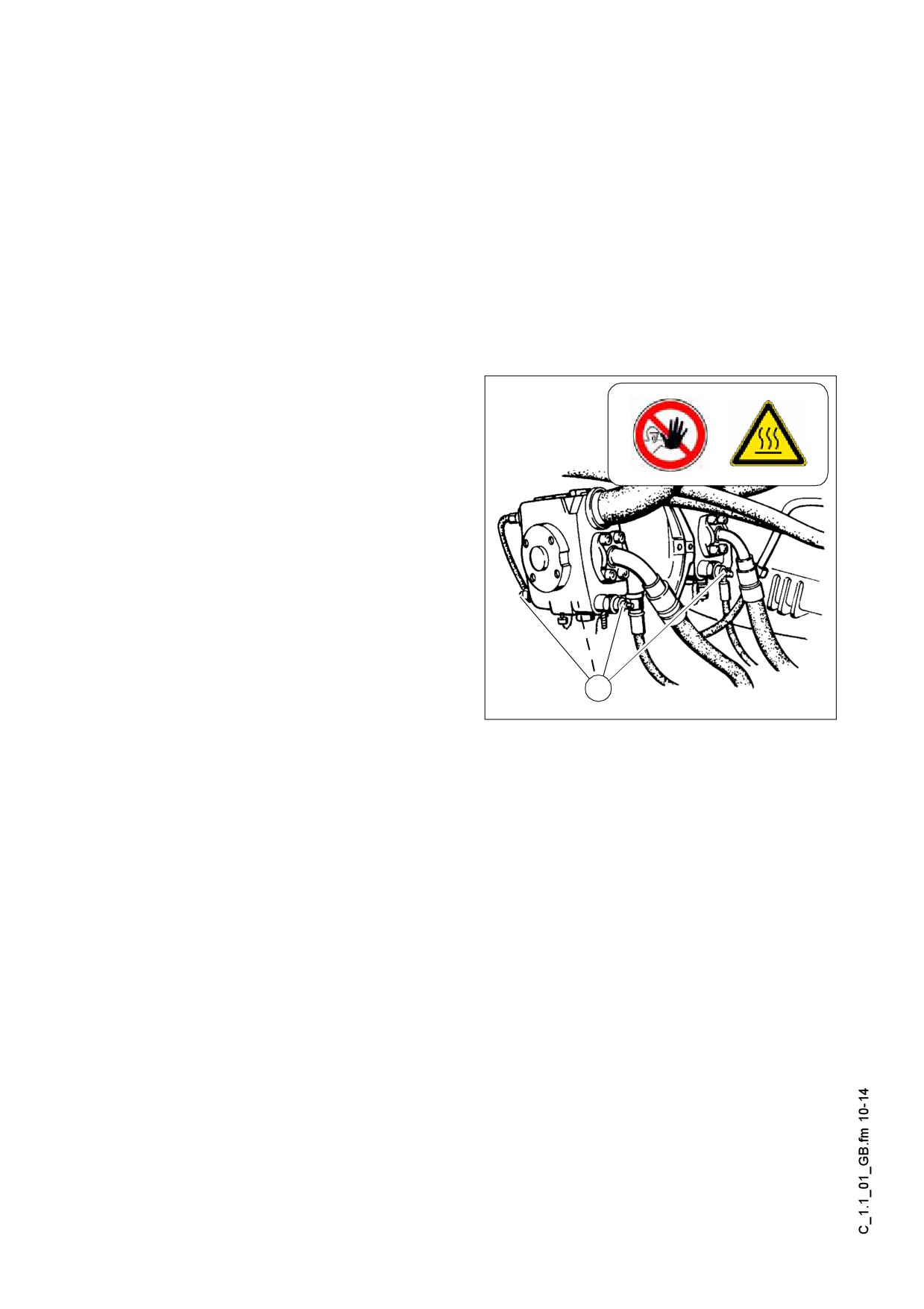
The engine compartment holds a hand-pump on the LH side, which must be actuated
to permit the towing of the machine.
Pressure for releasing the traction system brakes is built up with the hand pump.
Only release the traction system brakes
m
when the machine is sufficiently secured
against accidental rolling or is already
properly connected to the towing vehi-
cle.
- The four high pressure cartridges (1)
of the pumps of the traction drive must
be driven out by about 3 turns.
1
F0264_A1.TIF
C 1.1 10
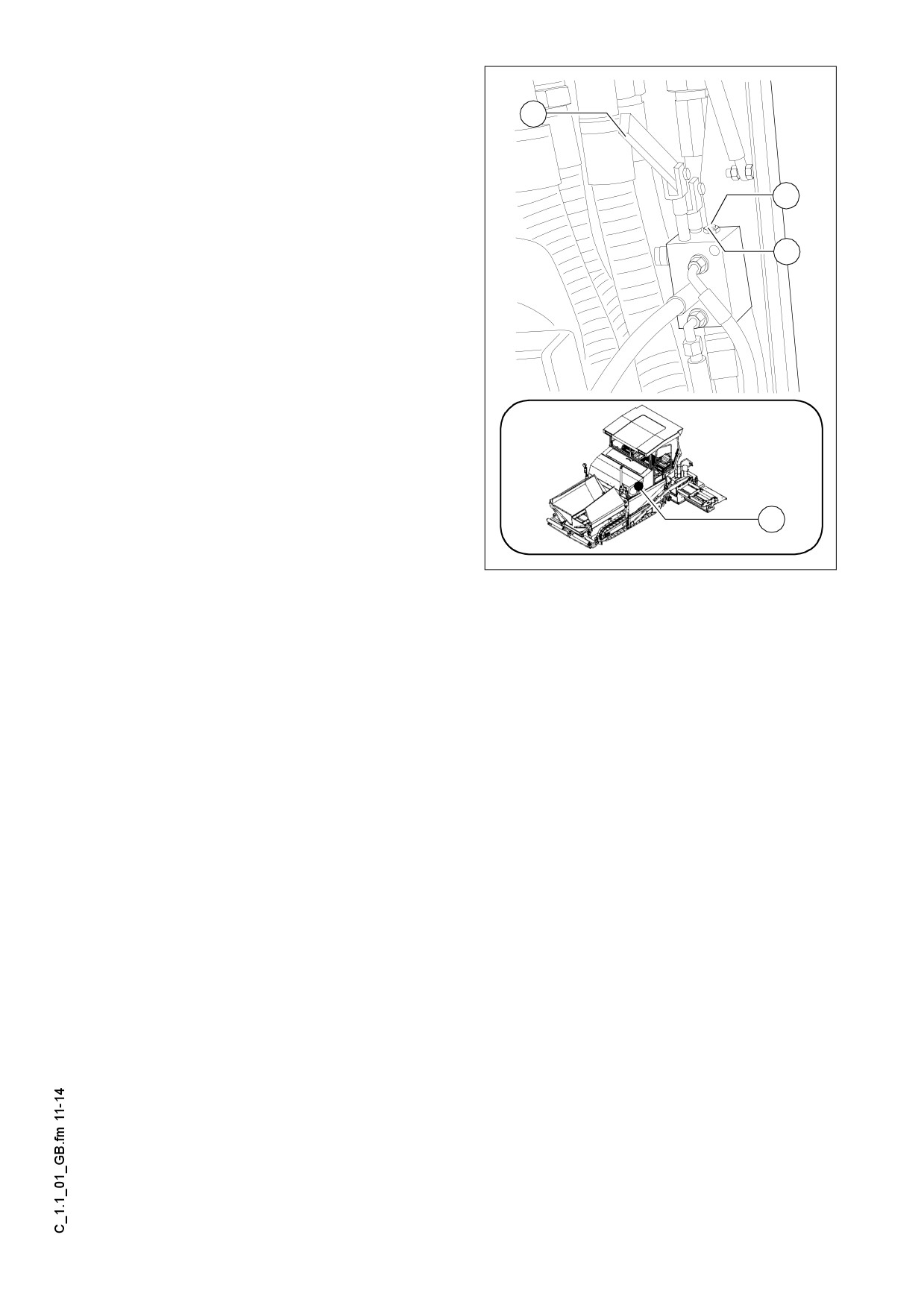
- Release lock nut (2), screw threaded
dowel (3) into pump as far as possible
and secure with lock nut.
4
- Actuate lever (4) of hand pump until
sufficient pressure has been built up
and traction system brakes have been
3
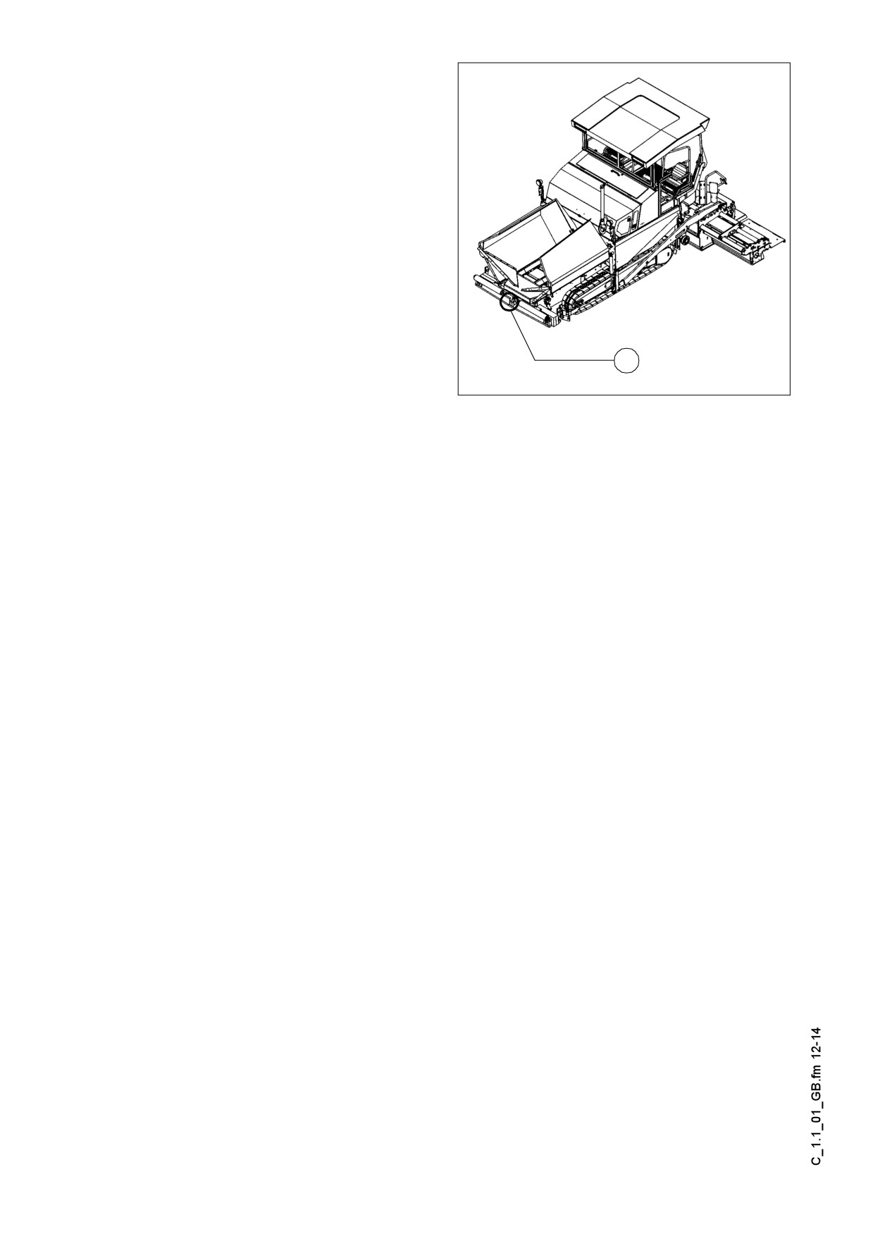
released.
- Attach the tow bar to the coupling (5)
located in the bumper.
2
A Now carefully and slowly tow the paver
finisher out of the construction area.
m Always only tow the shortest distance to
the means of transport or the next park-
ing possibility.
X
Pump.eps
C 1.1 11
Following towing, unscrew the threaded
dowel (3) a few turns again and lock with
the lock nut (2).
The high pressure cartridges (1) have to
be fully screwed back in to make the ma-
chine usable again.
The brakes of the traction drive are now
active again and the machine is secured
against accidental rolling away.
5
F121C.Tif
C 1.1 12
6
Safely parking the vehicle
When the paver finisher is parked at a lo-
m
cation accessible to the public, it must be
secured in such a way that unauthorized
persons or playing children cannot dam-
age the vehicle.
- Pull off the ignition key and the main
1
switch (1) and take it with you - do not
hide them somewhere on the ma-
chine.
F0077/0078_A1.EPS
Do not turn off main switch (1) until 15
m
seconds after the ignition has been turned off!
The engine electronics need this length of time to back up data.
A
- Protect the operating panel with the
dust cover (2) and lock it.
- Store loose parts and accessories in a
safe place.
2
Bedienpult_SPS_Kette_635_2.wmf/Vandalism.bmp
A Secure the dust cover (2) during opera-
tion with the lock on the terminal box un-
der the maintenance flap on the RH
side!
2
Dieseltank.eps/Vandalism.bmp
C 1.1 13
D 1.1
Operation
1
Safety regulations
Starting the engine, the traction drive, the conveyor, the auger, the screed or the lift-
f
ing devices can cause injuries or even the death of persons.
Make sure before starting any of these devices that no-one is working at, in or be-
neath the paver finisher or within its danger area!
- Do not start the engine or do not actuate any controls when this is expressly forbid-
den!
Unless otherwise specified, the controls may only be actuated when the engine is
running!
Never crawl into the auger tunnel or step into the hopper or onto the conveyor. Dan-
f
ger to life and limb!
- Always make sure during operation that no-one is endangered by the machine!
- Ensure that all protective covers and hoods are fitted and secured accordingly!
- When damages are detected, eliminate them immediately! Operation must not be
continued when the machine is defective!
- Do not let any persons ride on the paver finisher or the screed!
- Remove obstacles from the road and the work area!
- Always try to choose a drivers’s position that is opposite to the flowing traffic! Lock
the operating panel and the driver’s seat.
- Keep a sufficient safety clearance to overhanging objects, other machines and
points of danger!
- Be careful when travelling on rough terrain to keep the paver finisher from slipping,
tipping or turning over.
Always be the master over the machine; never try to use it beyond its capacities!
f
D 1.1 1
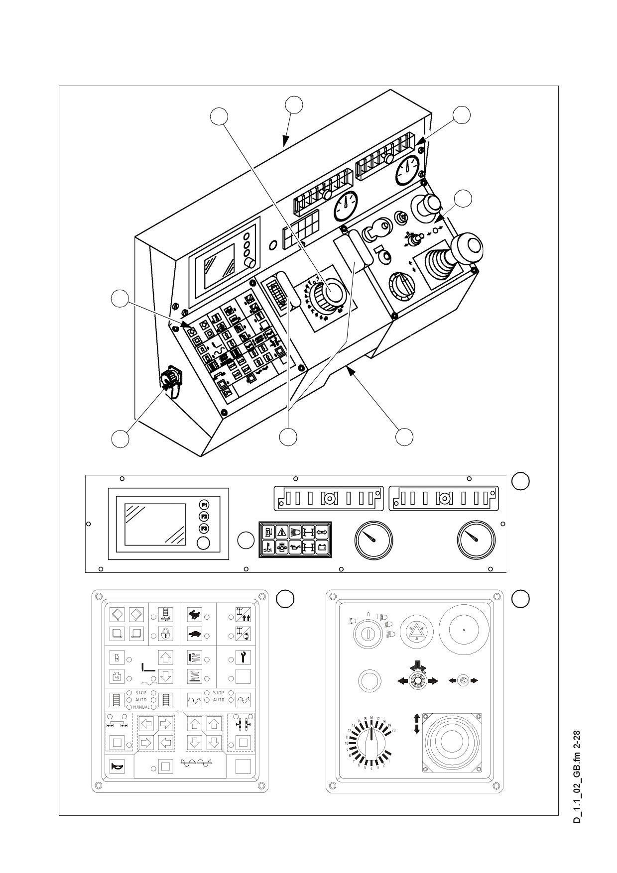
2
Operating elements
2.1
Operating panel
2
1
C
A
B
5
4
3
C
B
A
Bedienpult_SPS_Kette_635_3.bmp,Element1_SPS_Kette_635.bmp,Element2_SPS_Kette_635.bmp,Element3_Kette_635_2.bmp
D 1.1 2
m General notes on the observation of CE regulations
All functions of self-engaging buttons which might provoke a risk during start-up of
the diesel engine (conveying function of auger and conveyor) are set to STOP in
case of an emergency stop or a control restart. Changes of settings which are per-
formed when the diesel engine is at a standstill („AUTO” or „MANUAL”) are reset to
„STOP” when the diesel engine is started.
Turning on the spot (button 19) is reset to straight-ahead travel.
Item
Designation
Brief description
The steering wheel movement is transferred electrohydrauli-
cally.
Steering potentio-
(position
„0“
= straight
1
A For precision adjustment,
meter
ahead) refer to adjustment for straight ahead travel.
For turning on the spot, refer to switch (turning on the
spot).
For securing the movable operating panel against inadvertent
movement at the desired paver finisher height.
Retaining bracket
- Turn the knurled screw at the desired location into the des-
2
for operating panel
ignated notch and secure with the knurled nut.
f When not secured, the operating panel can move.
Danger of accidents during transportation!
In the case of seats which can be swung out beyond the ma-
chine contour (option), the operating panel can also be moved
beyond the basic width of the paver finisher.
Latch for operat-
3
Pull out the latch and move the operating panel; let the latch
ing panel
engage again.
f An unlatched operating panel can slide out of position.
Danger of accidents during transportation!
Lights up instrument panel A / B when the parking light is
4
Lights
switched on.
5
Connection
To connect input devices.
D 1.1 3
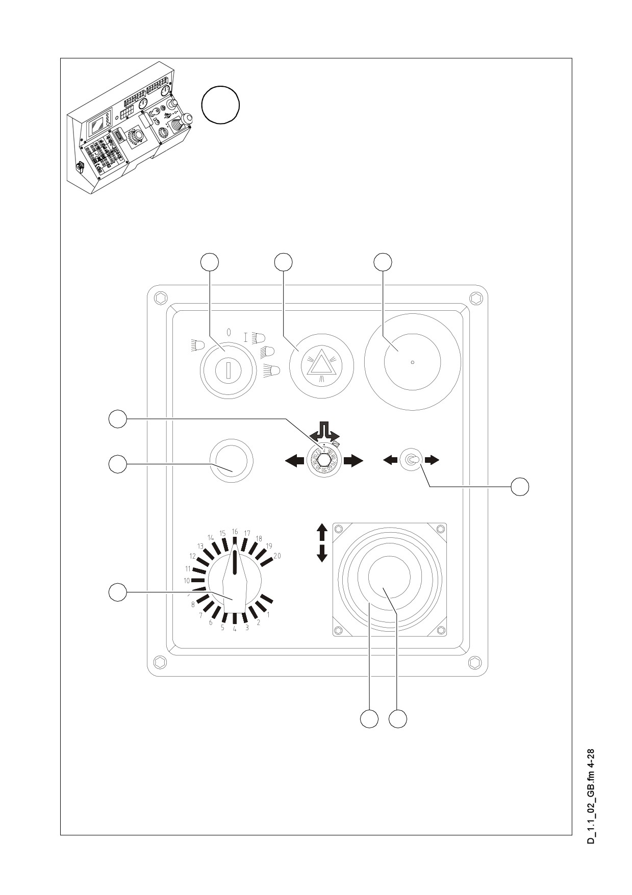
A
5
6
7
12
11
8
10
9
9a
Element2_SPS_Kette_635.bmp
D 1.1 4
Item
Designation
Brief description
Positions:
0 Ignition and light off
1
Ignition on
Parking/rear lights, instrument panel illumination,
Ignition lock and il-
5
working lights (if applicable)
lumination switch
Driving light
High beam
6
Not used
In the case of an emergency (danger to persons, possible col-
lision etc.), press in the button!
- Pressing the emergency stop button switches off the en-
gine, the drives and the steering system.
Making way, lifting the screed or other actions are then no
longer possible! Danger!
Emergency stop
7
- The emergency stop button does not shut off the gas heater
button
system.
Close the main shut-off valve and the valves on the bottles
by hand!
- In the case of electrical malfunctions, the engine must be
turned off manually at the leverage of the injection pump.
To restart the engine, the button must be pulled out again.
8
Not used
D 1.1 5
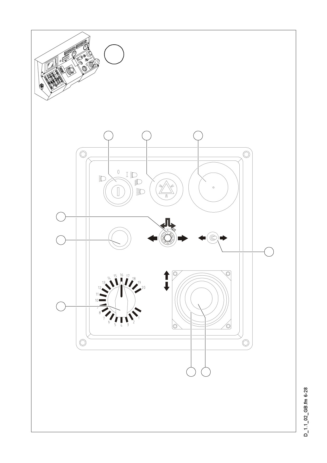
A
5
6
7
12
11
8
10
9
9a
Element2_SPS_Kette_635.bmp
D 1.1 6
Item
Designation
Brief description
For switching on the paver finisher functions and for continu-
ously regulating the traction speed - forward or reverse.
Zero position: starting is possible; engine at idling speed; no
traction drive
Drive lever
9
Depending on the position of the drive lever, the following
(forward - reverse)
functions can be activated:
Position 1: Conveyor and auger on.
Position 2: Screed motion (tamper/vibration) on; traction
drive on; increase speed until the stop is reached.
Use the preselector to set the maximum speed.
For setting the maximum speed that can be reached when the
drive lever is at its stop.
Preselector, trac-
10
tion drive
A The scale roughly matches the speed in m/min (during
paving).
Starting is only possible when the driver lever is in the neutral
11
Starter
position. All emergency stop buttons (on the operating panel
and the remote controls) must be pulled out.
Additional function for machines without synchronization or
when sensors in the caterpillar drives are defective.
Straight-ahead
Using this potentiometer, both chains can be synchronized for
12
travel synchroniza-
straight-ahead travel while driving:
tion
- Set the steering wheel to position „0”; then adjust the poten-
tiometer until the paver finisher is travelling straight ahead.
D 1.1 7
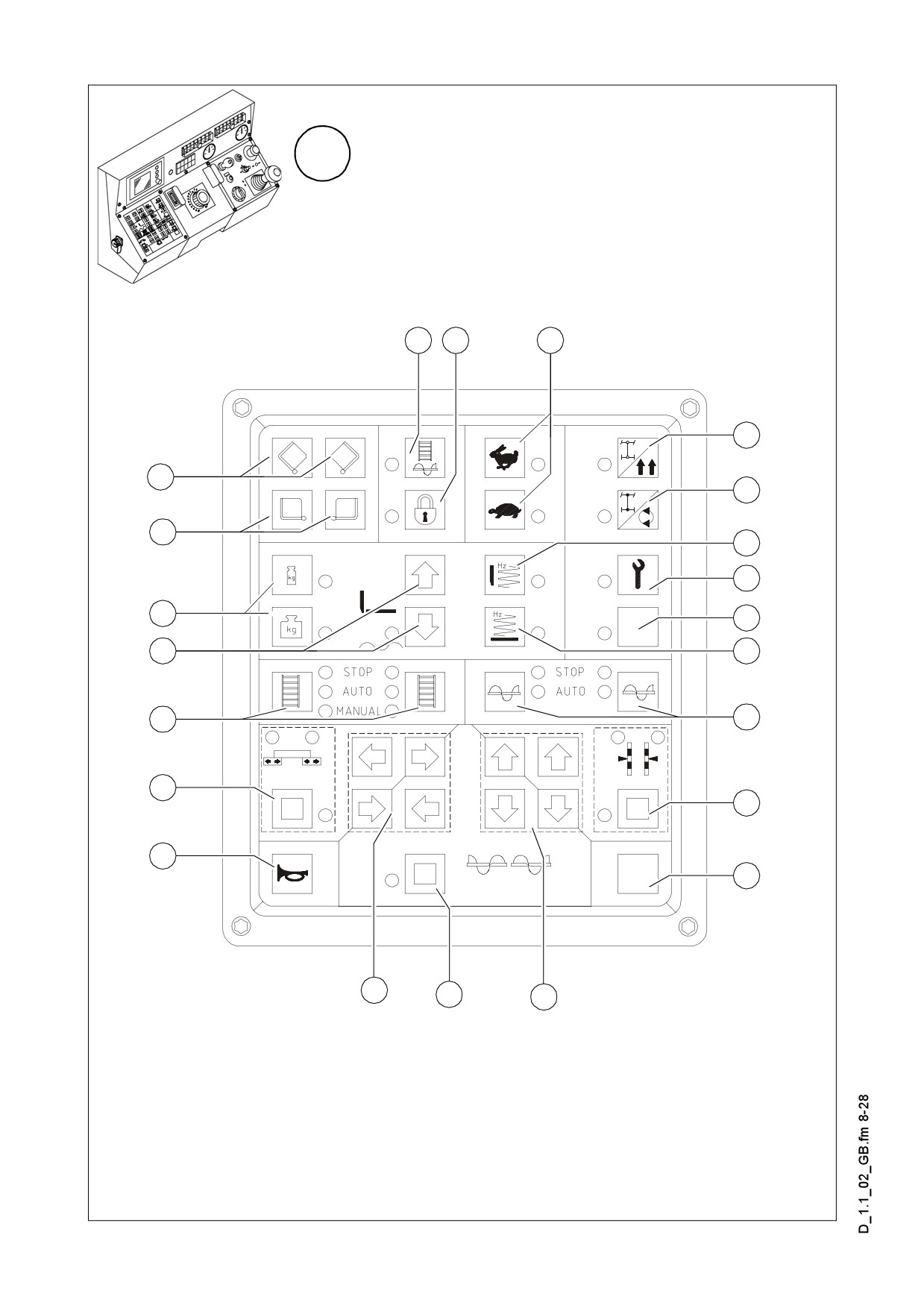
B
15
16
17
18
14
19
13
20
21
34
22
33
23
32
24
31
25
30
26
29
28
27
Element1_SPS_Kette_635.wmf
D 1.1 8
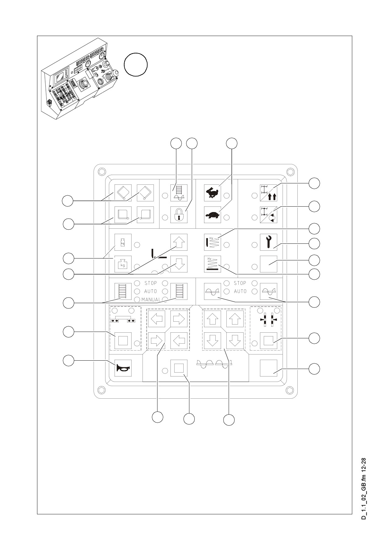
Item
Designation
Brief description
Push-button:
Left: open left hopper half
Right: open right hopper half
13
Open hopper
If both hoppers are hydraulically actuated at the same time
(1 valve), either the left button or the right button can be used
for operation.
Push-button:
Left: close left hopper half
Right: close right hopper half
14
Close hopper
Separate actuation (o):
Is required when paving in spaces where there is only limited
space at one side or when obstacles obstruct unloading of the
truck.
Self-engaging button with LED indication
Operating requirements: button 16 „OFF”
Button (15) is used for the filling function:
Filling the ma-
- The diesel engine speed is increased to the preselected
15
chine for paving
nominal speed and all conveying functions (conveyor and
auger) which are set to „Automatic” can be activated.
Switching off: Press button 15 again or tilt the drive lever to
the paving position.
Self-engaging button with LED indication
Button 16 locks all functions necessary for paving. Although
the individual functions are set to „Auto”, they are not activat-
ed when the drive lever is moved.
Main function
16
switch
The set-up is retained, allowing the machine to be re-posi-
tioned and unlocked at the installation site. Paving can be
continued by moving the drive lever.
A Button 16 is set to „ON” when restarting.
D 1.1 9
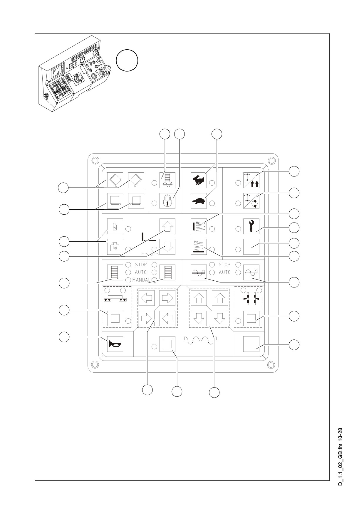
B
15
16
17
18
14
19
13
20
21
34
22
33
23
32
24
31
25
30
26
29
28
27
Element1_SPS_Kette_635.wmf
D 1.1 10

Item
Designation
Brief description
Self-engaging buttons with LED indication
Hare: transport speed
Traction drive
Tortoise: operating speed for paving
17
fast/slow
A When restarting, the buttons are set to working speed
(tortoise).
Self-engaging buttons with LED indication
A When restarting, the button is set to „Straight-ahead
travel”.
Straight-ahead
Normal position for straight-ahead travel.
18
travel
A If the button at the bottom has been inadvertently acti-
vated (with the steering knob (1) set to straight-ahead
travel), the paver finisher does not move. This is often
interpreted as a ‘malfunction’.
The paver finisher turns on the spot (the caterpillar chains run
in opposite directions) when the steering knob (1) is set to
„10”.
Steering knob turned to the left = paver finisher turns to the
left
Turning on the
Steering knob turned to the right = paver finisher turns to the
19
spot
right
f When the paver finisher turns, persons and objects
next to the paver finisher are in extreme danger. Watch
the area where the paver finisher turns!
Button 17 is set to „tortoise”.
Self-engaging button with LED indication
Operating requirements: button 16 must be set to „OFF”
Tamper
20
(screed-specific)
Switching function ON or OFF.
- The function is activated when moving the drive lever.
Set-up operation is actuated in conjunction with button 21.
When the machine is at a standstill, this button is used for the
commissioning of all working functions which are only activat-
ed when the drive lever (travelling machine) is moving.
21
Set-up operation
Button 21 „ON”
Button 16 „OFF”
The diesel engine speed is increased to the preselected set
value.
D 1.1 11
B
15
16
17
18
14
19
13
20
21
34
22
33
23
32
24
31
25
30
26
29
28
27
Element1_SPS_Kette_635.wmf
D 1.1 12

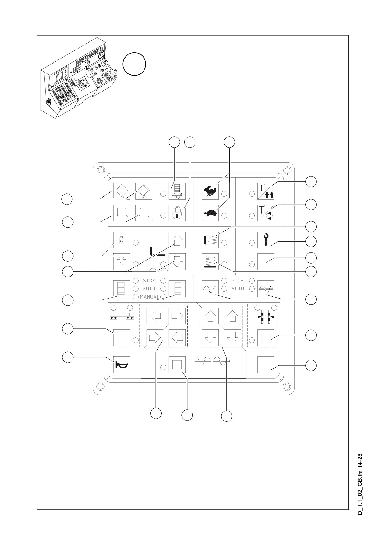
Item
Designation
Brief description
22
Not used
23
Vibration
Operation and application: see button (20).
Self-engaging buttons with LED indication
Toggling between two switching conditions.
Stop: Operational readiness
24
Auger left/right
Auto
Reset to STOP in case of an emergency stop or a restart.
Button 16 locks the conveying function.
Self-engaging button with LED indication
For manually actuating the levelling cylinders when automatic
levelling is switched off.
The switch on the remote control must be set to „manual”.
LED „C” (left) and LED „D” (right) indicate the setting.
Switched off by pressing the button again or by pressing but-
Levelling cylinder
25
ton 28 or 31.
left/right
Adjustment of the levelling cylinders occurs by using the ap-
propriate button in the pad (right) for the directions of move-
ment (27).
A This function is active even if the remote control is dis-
connected!
26
Not used
Pad (right) for di-
Used in conjunction with buttons 25, 28 and 31; releases a
27
rections of move-
movement towards the indicated direction.
ment
D 1.1 13
B
15
16
17
18
14
19
13
20
21
34
22
33
23
32
24
31
25
30
26
29
28
27
Element1_SPS_Kette_635.wmf
D 1.1 14

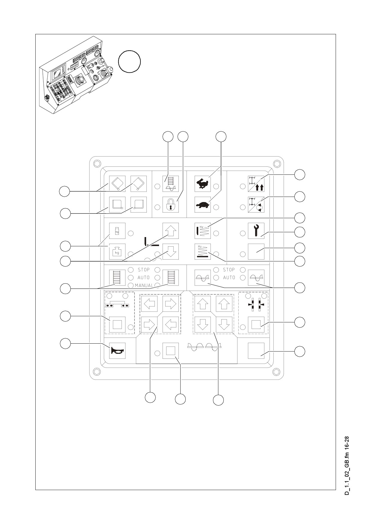
Item
Designation
Brief description
Self-engaging button with LED indication
Switched off by pressing the button again or by pressing but-
ton 25 or 31.
1. „MANUAL” auger operation
Requirements: button 24 must be set to „AUTO”
„MANUAL” auger
- Using the buttons in the pad (left) for the directions of move-
operation and lift-
28
ment (29), the conveying speed of the automatic function
ing/lowering the
can be exceeded with full conveying performance in the di-
auger
rection of the corresponding arrow.
2. Lifting/lowering the auger
- Using the buttons in the pad (right) for the directions of
movement (27), the auger is lifted or lowered to the direc-
tion of the arrow.
Pad (left) for the di-
Used in conjunction with buttons 25, 28 and 31; releases a
29
rections of move-
movement to the indicated direction.
ment
Must be activated in the case of emergencies and to indicate
30
Horn
that the machine starts to move!
Self-engaging button with LED indication
Switched off by pressing the button again or by pressing but-
Extend/retract
ton 25 or 28.
31
screed parts
Using the buttons in the pad for the directions of movement,
the screed is moved to the indicated direction of the arrow.
LED „A” and LED „B” indicate the vario screeds.
Self-engaging buttons with LED indication
To change between the three switching states, press the but-
ton again:
STOP: Operational readiness
32
Conveyor, left/right
AUTO
MANUAL
Reset to STOP in case of an emergency stop or a restart.
Button 16 locks the conveying function.
D 1.1 15
B
15
16
17
18
14
19
13
20
21
34
22
33
23
32
24
31
25
30
26
29
28
27
Element1_SPS_Kette_635.wmf
D 1.1 16

Item
Designation
Brief description
Push-button function Lift screed
AIf the drive lever is in its central position, the speed
of the engine rises automatically when moving.
Self-engaging button with LED indication
Lower screed/screed in floating position
The button 16 must be set to „OFF”
Screed floating position: Pressing the button turns the LED
ON and prepares the screed for „floating position”, which is
activated by the actuated drive lever (9). Pressing the button
33
Screed position
again or pressing the button Lift screed turns the LED off.
Lower screed:
- Button function: Keep the button depressed for more than
1.5 sec (LED On). As long as the button is pressed, the
screed is lowered. When the button is released, the screed
will stop again. (LED Off).
- Resting function: Briefly press the button (LED On) - the
screed is lowered. Press the button briefly again (LED Off) -
the screed stops.
m During paving, the screed must always be in the float-
ing position. In the intermission, the screed switches to
standby position.
Self-engaging buttons with LED indication
Switched off by pressing the button again or by toggling be-
tween the two buttons.
Screed charging/
34
relieving device
For charging/relieving the screed to influence traction and the
compacting ratio.
- To pre-adjust the pressure of the hydraulic oil, set this but-
ton and button 21 to „ON”.
D 1.1 17
C
51
52
35
36
38
40
41
42
43
44
45
46
47
48
49
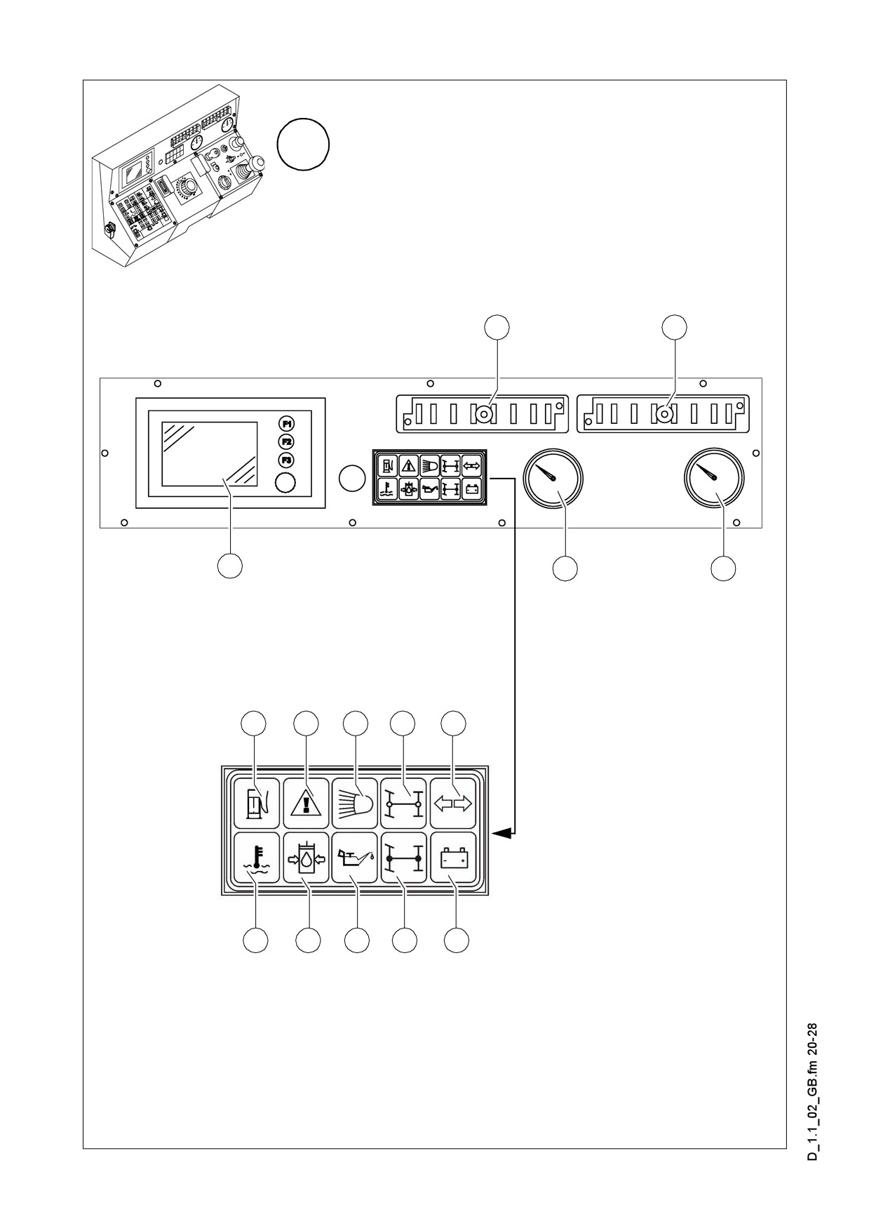
Element3_SPS_Kette_635_2.wmf/Leuchtmodul_SPS_Kette_635.bmp
D 1.1 18

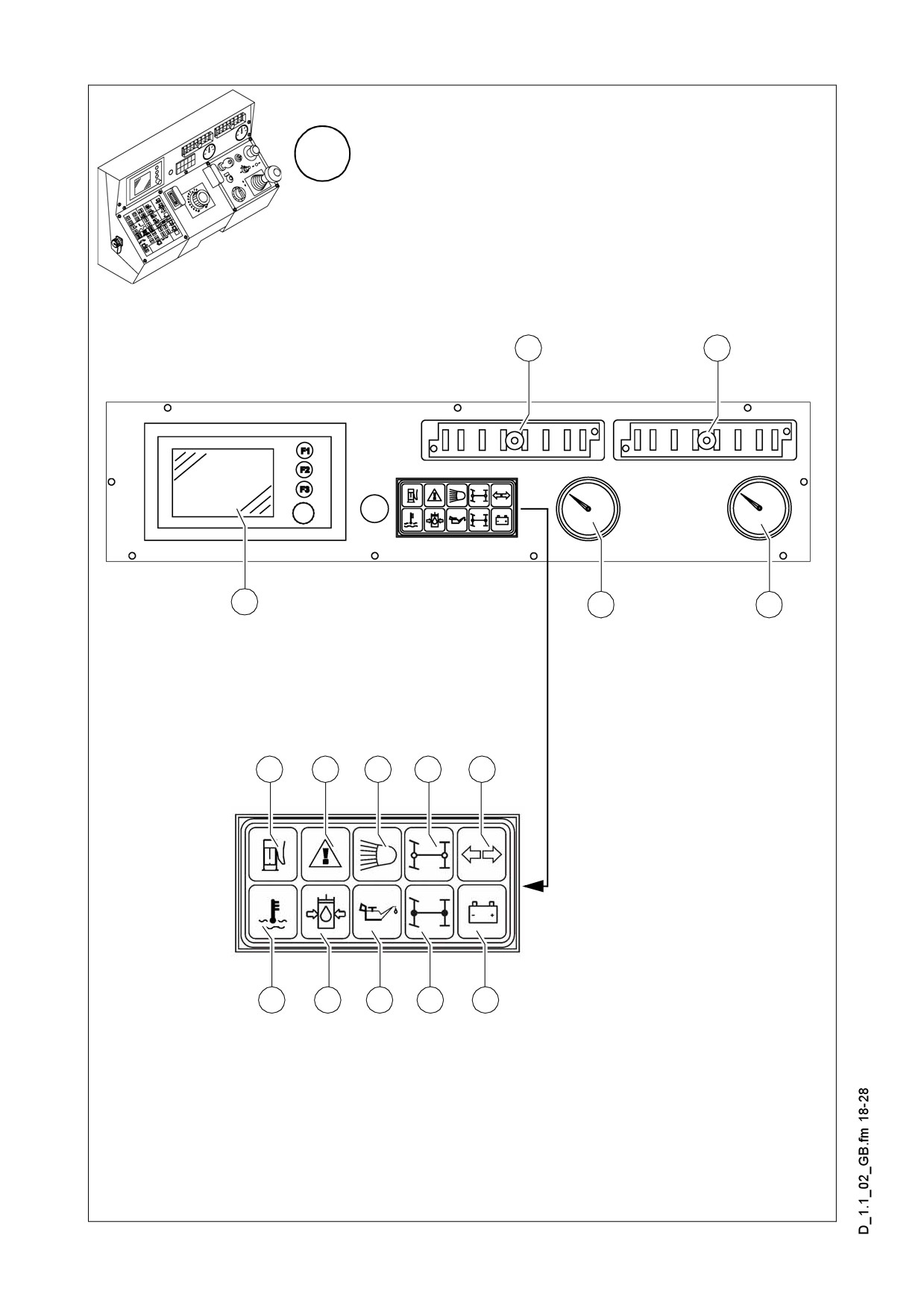
Item
Designation
Brief description
To query, set and save various operating status and functions
Control setting and
35
as well as for displaying messages related to machine and en-
display terminal
gine.
Normal display up to 120 °C = 248 °F.
In case of higher temperature stop the machine, (set
Hydraulic oil ther-
m
36
drive lever (9) to neutral position), and let the engine
mometer
cool at idling speed. Find the cause and eliminate the
fault.
37
Not used
Always heed the fuel gauge.
38
Fuel gauge
m Do not completely empty the diesel tank! Otherwise,
the entire fuel system must be ventilated.
D 1.1 19
C
51
52
35
36
38
40
41
42
43
44
45
46
47
48
49
Element3_SPS_Kette_635_2.wmf/Leuchtmodul_SPS_Kette_635.bmp
D 1.1 20

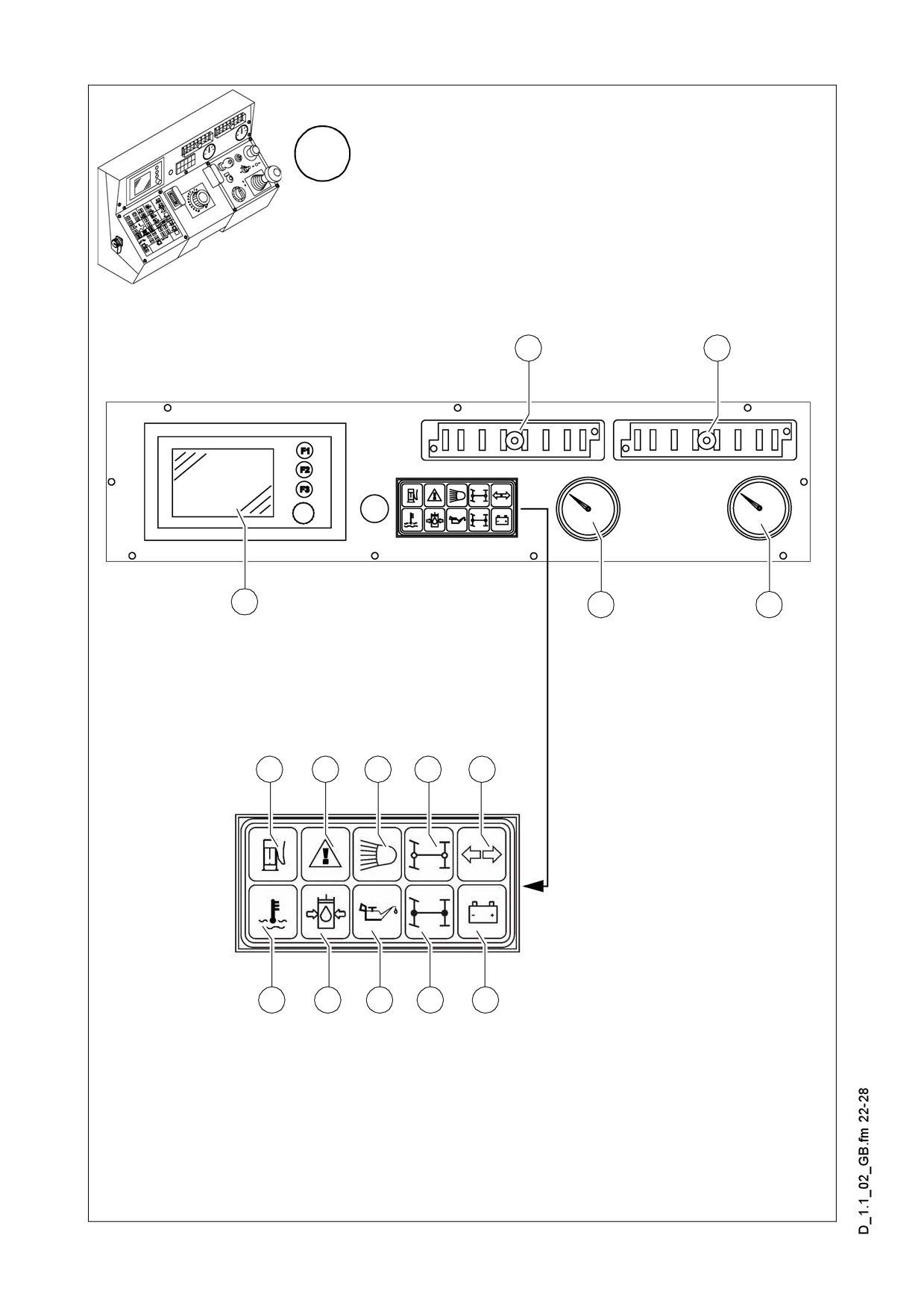
Item
Designation
Brief description
This light is on, if the water separator of the fuel system has
established a too high water level.
In order to avoid the damage of the traction engine
m
Alarm light (red)
drain the separated water immediately according to the
40
„Water in the fuel“
operation manual.
m The fault is indicated together with the „Error message“
light.
It indicates that a fault has occurred in the traction engine. De-
pending on the type of the fault the operation of the machine
can be continued temporarily, or in case of a major fault it can
be stopped immediately.
All the faults shall be eliminated as soon as possible!
Error message
41
(yellow)
A The error message is displayed on the setting and dis-
play terminal.
A After the ignition is turned on, the light is on for a few
seconds for check-up.
Lights up when the high beam is switched on (at the ignition
High beam indica-
42
key (18)).
tor (blue)
f Avoid blinding the oncoming traffic!
43
Not used
44
Not used
It is lit on, when the engine temperature is too high.
m The output of the engine drops automatically. (Further
travel remains possible). Stop the paver finisher, (set
drive lever to neutral position), and let the engine cool
Indicator light of
at idling speed. Find the cause and if necessary elimi-
45
engine tempera-
nate it (see Chapter „Operating Faults“). Upon cooling
ture (red)
down to normal temperature, the engine will work
again at full capacity.
A The fault is indicated together with the „Error message“
light.
Must go out shortly after the engine has been started. Ob-
serve warm running. The hydraulic oil is possibly too cold and
Oil pressure indi-
stiff.
cator for the hy-
46
m Do not switch on the traction drive when the lamp does
draulic traction
not go out (see the section „Malfunctions”).
drive (red)
A The lamp goes out when the pressure drops below
2.8 bar = 40 psi.
D 1.1 21
C
51
52
35
36
38
40
41
42
43
44
45
46
47
48
49
Element3_SPS_Kette_635_2.wmf/Leuchtmodul_SPS_Kette_635.bmp
D 1.1 22