DYNAPAC Paver finisher F 121 C, F 141 C Type 635. Operation & Maintenance (Order number: 4812026925) - page 1

OPERATION
&
MAINTENANCE
Paver finisher
F 121 C
F 141 C
Type 635
Keep this manual for future reference
Order number for this manual: 4812026925
05-0108
635
Table of contents
V
Preface
1
1
General safety instructions
2
1.1
Acts, directives, accident prevention regulations
2
1.2
Warning instructions
2
1.3
Prohibitive signs
4
1.4
Protective gear
5
1.5
Environmental protection
6
1.6
Fire prevention
6
1.7
Further instructions
7
A
Correct use and application
1
B
Vehicle description
1
1
Application
1
2
Description of assemblies and functions
2
2.1
Vehicle
3
Construction
3
3
Danger zones
6
4
Safety devices
7
4.1
Emergency stop button
7
4.2
Steering system
7
4.3
Horn
7
4.4
Ignition key / lights
7
4.5
Main switch (17)
8
4.6
Hopper transport safeguards (18)
8
4.7
Screed transport safeguard (19)
8
4.8
Latch for protective roof (20)
8
5
Technical data, standard configuration
10
5.1
Dimensions (all dimensions in mm)
10
5.2
Allowed angle of rise and slope
11
5.3
Allowed angle of driving up
11
5.4
Weights F 121 C (all weights in t)
12
5.5
Weights F 141 C (all weights in t)
12
5.6
Performance data F 121 C
13
5.7
Performance data F 141 C
14
5.8
Traction drive/chassis
15
5.9
Engine F 121 C
15
5.10
Engine F 141 C
15
5.11
Hydraulic system
15
5.12
Material compartment (hopper)
16
5.13
Material conveying
16
5.14
Material distribution
16
5.15
Screed lifting device
17
5.16
Electrical system
17
6
Location of instruction labels and identification plates
18
6.1
Identification label for the paver finisher (6)
20
1
7
EN standards
21
7.1
Continuous sound level F121C, Deutz TCD 2012L06
21
7.2
Operating conditions during measurement
21
7.3
Measuring point configuration
21
7.4
Continuous sound level F141C, Deutz TCD 2013L06
22
7.5
Operating conditions during measurement
22
7.6
Measuring point configuration
22
7.7
Vibration acting on the entire body
23
7.8
Vibrations acting on hands and arms
23
7.9
Electromagnetic compatibility (EMC)
23
C1.1
Transportation
1
1
Safety regulations for transportation
1
2
Transportation on low-bed trailers
2
2.1
Preparations
2
2.2
Driving onto the low-bed trailer
4
2.3
Secure the paver finisher in its position to the low-bed trailer:
5
2.4
After transportation
5
3
Transportation
6
3.1
Preparations
6
3.2
Traction drive:
8
4
Loading by crane
9
5
Towing
10
6
Safely parking the vehicle
13
D1.1
Operation
1
1
Safety regulations
1
2
Operating elements
2
2.1
Operating panel
2
3
Remote control
24
2
D2.0
Operation
1
1
Operation of the input and display terminal
1
Allocation of the keyboard of the display
1
1.1
Working in the menu
2
Menu structure of the setting and display options
3
Main menu 00
4
Display and function menu
4
Menu 01 - Engine speed
5
Submenu 101 - Setting the engine speed
5
Menu 02 - Measuring value of drive engine
6
Submenu 103 - Display of measuring value Drive engine
6
Menu 03 - Trip meter and fuel gauge
7
Submenu 301 - Road section, fuel consumption display/reset
7
Menu 04 - Emergency function / stopping the screed and turning
on the tamper
8
Submenu 401 - Emergency functions adjustment
8
Menu 05 - Layer thickness
9
Submenu 501 - Preselection of layer thickness
9
Submenu 502 - Setting the speed of auger
10
Submenu 503 - Adjustment of the speed of conveyor
10
Menu 06 - Screed charging
11
Submenu 102 - Starting load setting
11
Menu 07 - Screed type
12
Submenu 701 - Setting the screed type
12
Menu 08 - Service hour meter
13
Menu 09 - Service
14
Submenu 201 - Password prompt
14
Menu 10 - Error memory
15
Error message display:
15
Error display
15
Menu 11 - Error memory Computer of machine operation
16
Error message display:
16
Error display
16
Menu 12 - Program version
17
Menu 13 - Terminal settings
18
Submenu 104 - Terminal settings
18
1.2
Further messages on the display
19
2
Terminal error messages
20
2.1
Instructions related to error messages
26
2.2
Fault codes of the traction engine
27
2.3
Error messages
29
2.4
FMI-codes
34
2.5
Special functions
35
Emergency operation program for the case of keyboard failure
35
Reversible conveyor
36
3
D3.1
Operation
1
1
Operating elements on the paver finisher
1
Batteries (71)
1
Battery main switch (72)
1
Transport safeguards for the hopper (73)
2
Mechanical screed transport safeguard
(to the left and the right beneath the driver’s seat) (74)
3
Seat lock (behind the driver’s seat) (75)
3
Separator fluid spraying system (80) (o)
4
On / off switch for additional headlight in the roof (85):
5
On / off switch for fuel tank filler pump (85a)
5
On / off switch special lighting (85b)
5
On/Off switch Exhaust of asphalt vapours (85c)
5
On/Off switch of work headlights (85d):
6
On/Off switch of flasher (85e):
6
230 V On / Off switch Connection sockets (85f)
6
Locking of the collapsible roof (LH and RH on the roofs console) (86): .6
Hydraulic folding roof (87) (o)
7
Electric setting of the transportation volume of the conveyor (o) (88)
8
Conveyor limit switches (89)
9
Ultrasonic auger limit switches (90) (left and right)
10
Sockets for working lights (left and right) (92)
10
Pressure control valve for screed charging/relieving (93)
11
Pressure control valve for screed stop with pretensioning (93a)
11
Pressure gauge for screed charging/relieving and screed stop
with pretensioning (93b)
11
Central lubrication unit (o) (100)
12
Track cleaner (o) (101)
12
Particle filter - control light (102) (o)
13
Front and side window (o) (103)
14
Adjustment of screed eccentric (o) (104)
15
4
D4.1
Operation
1
1
Preparation of operation
1
Required devices and aids
1
Before starting work (in the morning or when starting paving)
1
Checklist for the machine operator
2
1.1
Starting the paver finisher
4
Before starting the paver finisher
4
„Normal” starting
4
External starting (starting aid)
5
After starting
6
Indicator lamps
6
Oil pressure indicator lamp for the traction drive (46)
7
Battery charge indicator (49)
8
1.2
Operation in case of transportation
9
Lifting and securing the screed
9
Driving and stopping the paver finisher
10
Switching off and securing the paver finisher
10
1.3
Preparations for paving
11
Separating agent
11
Screed heater
11
Direction marks
12
Loading/distributing material
12
1.4
Starting for paving
14
1.5
Checks during paving
16
paver finisher function
16
Quality of the layer
16
1.6
Paving with screed stop and screed charging/relieving
16
General
16
Screed charging/relieving
17
Screed stop with prestressing
18
Adjusting the pressure (o)
19
Screed stop (with prestressing):
19
For screed charging/relieving:
19
1.7
Interrupting/terminating operation
20
During breaks: (e.g. the material supply truck is late)
20
During extended interruptions (e.g. lunch break)
20
When work is finished
20
2
Malfunctions
23
2.1
Problems during paving
23
2.2
Malfunctions on the paver finisher or screed
25
3
Emergency device/steering, drive system
28
5
E01
Set-up and modification
1
1
Special notes on safety
1
2
Auger
2
2.1
Height adjustment
2
2.2
Auger crossbeam installed in a fixed position
2
2.3
Mechanical adjustment with ratchet (optional)
3
2.4
In case of hydraulic adjustment (option)
3
2.5
Auger extension, auger type I
5
2.6
Mounting extension parts
6
2.7
Mounting support tube extensions
7
2.8
Installing tunnel plates
8
2.9
Installing additional braces
9
2.10
Auger mounting chart for ø 310 mm auger
10
2.11
Auger mounting chart for ø 380 mm auger
11
3
Auger extension, auger type II
12
3.1
Mounting extension parts
13
3.2
Auger modification plan
15
4
Screed
17
5
Electrical connections
17
5.1
Remote controls
17
5.2
Grade control
17
5.3
Auger limit switches
17
5.4
Working lights
17
F1.0
Maintenance
1
1
Notes regarding safety
1
F2.4
Maintenance overview
1
1
Maintenance review
1
F3.0
Maintenance - Conveyor
1
1
Maintenance - Conveyor
1
1.1
Maintenance intervals
2
1.2
Points of maintenance
3
Chain tightness of the conveyor (1)
3
The drive of conveyor (to the left/to the right) (2)
4
F4.2
Maintenance - Auger
1
1
Maintenance - Auger sub-unit I
1
1.1
Maintenance intervals
2
1.2
Points of maintenance
3
Auger - outer bearing (1)
3
Auger middle bearing (2)
3
Auger - drive gear neck bearing (3)
4
Auger bevel gear (on the RH and LH sides) (4)
5
6
F5.1
Maintenance - Engine
1
1
Maintenance - engine sub-unit
1
1.1
Maintenance intervals
2
1.2
Points of maintenance
4
Engine fuel tank (1)
4
Engine lube-oil system (2)
5
Engine fuel system (3)
7
Engine air filter (4)
9
Coolant system of the engine (5)
10
Engine drive belt (6)
10
Engine exhaust system (7)
11
F6.0
Maintenance - Hydraulic system
1
1
Maintenance - hydraulic system
1
1.1
Maintenance intervals
2
1.2
Points of maintenance
3
Hydraulic oil tank (1)
3
Suction/return flow hydraulic filter (2)
4
Venting the filter:
5
High pressure filter (3)
6
Pump distribution gear (4)
7
Hydraulic hoses (5)
8
F7.1
Maintenance - running gear
1
1
Maintenance - running gear
1
1.1
Maintenance intervals
2
1.2
Points of maintenance
3
Track tightness (1)
3
Planetary gear (2)
4
7
F8.1
Maintenance - Electronic System
1
1
Maintenance - Electronic System
1
1.1
Maintenance intervals
2
1.2
Points of maintenance
5
Batteries (1)
5
Generator (2)
6
Adjustment of belt tightness
8
Replacement of belt
9
Checking / adjusting belt tension:
10
If necessary, adjust the belt tension:
10
Electric fuses (3)
11
Type of machine: Conventional electronics
11
Switch box
11
Fuses in the switching cabinet (B)
12
Relays in the switching cabinet (C)
13
Fuses on the operating panel
14
Relays on the operating panel
15
Type of machine: PLC- electronics
16
Switch box
16
Fuses in the switching cabinet
17
Relays in the switching cabinet (C)
19
Fuses on the operating panel
20
F9.0
Maintenance - Points of lubrication
1
1
Maintenance- Points of lubrication
1
1.1
Maintenance intervals
2
1.2
Points of maintenance
3
Central lubrication (1)
3
Bearings (2)
7
F10.0
Checks, decommissioning
1
1
Tests, check-up, cleaning, stopping
1
1.1
Maintenance intervals
2
2
General observation
3
3
Checks by a specialist
3
4
Cleaning
4
5
Conservation of paver finisher
5
5.1
Downtime up to 6 months
5
5.2
Downtime between 6 months and 1 year
5
5.3
Re-commissioning:
5
F11.0
Lubricants and Fuels
1
1
Lubricants and fuels
1
1.1
Hydraulic oil
2
1.2
Instructions referring to the oil types applied
3
1.3
Filling volumes
4
2
Instructions to change from mineral oil to synthetic oil /
from synthetic oil to mineral oil
8
2.1
Caterpillar drive - planetary gear
8
8
V Preface
Safe operation of the machine requires specific knowledge that is imparted by the
present operating instructions. The information is provided in a concise, clearly struc-
tured form. The individual chapters are arranged in alphabetical order and every
chapter starts with page 1. The individual pages are identified by the chapter letter
and the page number.
Example: Page B 2 is the second page of chapter B.
These operating instructions cover various machine options. Make sure that during
operation and maintenance work the description appropriate to the machine option is
used.
Safety instructions and important notes are identified by the following pictograms:
f Precedes safety instructions that must be observed in order to prevent danger to per-
sonnel.
m Precedes notes that must be observed to prevent damage to equipment.
A Precedes general notes and explanations.
t Used to indicate standard equipment.
o Used to indicate optional equipment.
In the interest of continued development, the manufacturer reserves the right to make
changes to the machine (which will not, however, change the essential features of the
type of machine described) without updating the present operating instructions at the
same time.
Dynapac GmbH
Wardenburg
Ammerländer Strasse 93
D-26203 Wardenburg / Germany
Telephone: +49 / (0)4407 / 972-0
Fax:
+49 / (0)4407 / 972-228
V 1

1
General safety instructions
1.1
Acts, directives, accident prevention regulations
The locally applicable acts, directives and accident prevention regulations shall be
A
observed, even if the attention is not specifically directed to these.
The operator himself shall be responsible for the observation and performance of the
related regulations and actions!
The following alerts, prohibitions and instructions refer to the risks to which people,
A
machinery and environment are exposed.
Ignoring these instructions, bans and commands may lead to fatal injuries!
A
Furthermore, the Dynapac publication "Directives for the correct and specified appli-
A
cation of pavers" shall also be observed.
1.2
Warning instructions
Warning pointing to hazardous place or danger!
Not observing the warning instructions may lead to injuries of life
and limb!
Warning: risk of pulling in!
m In this area / with these equipment as a result of rotating or trans-
portation parts, there is a risk of pulling in!
Perform each operation only with equipment swicthed off!
Attention: electric voltage!
m All maintenance and repair work on the screed's electrical system
must always be carried out by an electrician!
Attention: suspended load!
m Never stand under suspended load!
Warning: risk of squeezing!
m Risk of squeezing arises due to the operation of certain parts, use
of some functions and the movement of the machine.
Always make sure that no one stays in the areas exposed to risk!
V 2

Attention: risk of hand injury!
Attention: hot surfaces or hot liquids!
Warning, risk of falling off!
Attention: hazardous batteries!
Attention: materials harmful to health and irritating substances!
Attention: flammable materials!
Attention: gas bottles!
V 3

1.3
Prohibitive signs
It is prohibited to open / step on / reach into / perform / adjust
during operation or when the traction engine is running!
Do not start the engine/drive!
Maintenance and repair works can be carried out only with the Die-
sel engine turned off!
Do not sprinkle with water!
Do not extinguish with water!
Do-it-yourself maintenance is prohibited!
Maintenance can be performed by skilled professionals only!
A Contact the Dynapac service!
Danger of fire: do not use open flame and no smoking!
Do not turn on!
V 4

1.4
Protective gear
A The applicable local regulations may define the use of different protective gear!
Observe these specifications!
Protect your eyes with googles!
Wear appropriate head protection!
Protect your hearing with appropriate ear mufflers!
Protect your feet with safety footwear!
Always wear tight, conforming working coveralls!
Wear visibility vest for good visibility!
In case of polluted air, wear respiratory mask!
V 5
1.5
Environmental protection
A The locally applicable acts, directives and waste disposal regulations shall be ob-
served, even if the attention is not specifically directed to these.
During cleaning, maintenance and repair operation the materials polluting water e.g.:
- lubricants (oils, grease)
- hydraulic oil
- gas oil
- coolant
- detergents
may not enter the soil or the sewer system!
These materials shall be collected, stored, transported in the correct
containers until professional disposal!
Material harmful for the environment!
1.6
Fire prevention
A The applicable local regulations may specify the mounting of appropriate fire extin-
guishers!
Observe these specifications!
Fire fighting device
(optional equipment)
V 6
1.7
Further instructions
m Observe the manufacturer's and other instructions!
A e.g. the maintenance instructions of the engine manufacturer
m Description / figure in case of an electrically heated design!
m Description / figure in case of an electrically heated design!
V 7
A
Correct use and application
The “Guidelines for the Correct Use and Application of Paver finishers” compiled by
A
Dynapac are included in the scope of delivery for the present machine. The guide-
lines are part of the present operating instructions and must always be heeded. Na-
tional regulations are fully applicable.
The road construction machine described in the present operating instructions is a
paver finisher that is suited for laying mixed materials, roll-down concrete or lean-
mixed concrete, track-laying ballast and unbound mineral aggregates for foundations
for paving.
This machine shall be used, operated and maintained for the purpose of the intended
work as included in the operation manual. Any other use is regarded as improper use
and can cause injury to persons or damage to the paver finisher or other equipment
or property.
Any use going beyond the range of applications described above is regarded as im-
proper use and is expressly forbidden! Especially in those cases where the paver fin-
isher is to be operated on inclines or where it is to be used for special purposes
(construction of dumps, dams), it is absolutely necessary to contact the manufacturer.
Duties of the user: A “user” within the meaning of the present operating instructions
is defined as any natural or legal person who either uses the paver finisher himself,
or on whose behalf it is used. In special cases (e.g. leasing or renting), the user is
considered the person who, in accordance with existing contractual agreements be-
tween the owner and the user of the paver finisher, is charged with the observation
of the operating duties.
The user must ensure that the paver finisher is only used in the stipulated manner and
that all danger to life and limb of the operator, or third parties, is avoided. In addition
to this, it must be ensured that the relevant accident prevention regulations and other
safety-related provisions as well as the operating, servicing and maintenance guide-
lines are observed. The user must also ensure that all persons operating the equip-
ment have read and understood the present operating instructions.
Mounting of attachments: The paver finisher must only be operated in conjunction
with screeds that have been approved by the manufacturer. Mounting or installation
of any attachments that will interfere with or supplement the functions of the paver fin-
isher is permitted only after written approval by the manufacturer has been obtained.
If necessary, the approval of local authorities has to be obtained.
Any approval obtained from local authorities does not, however, make the approval
by the manufacturer unnecessary.
A 1
B Vehicle description
1
Application
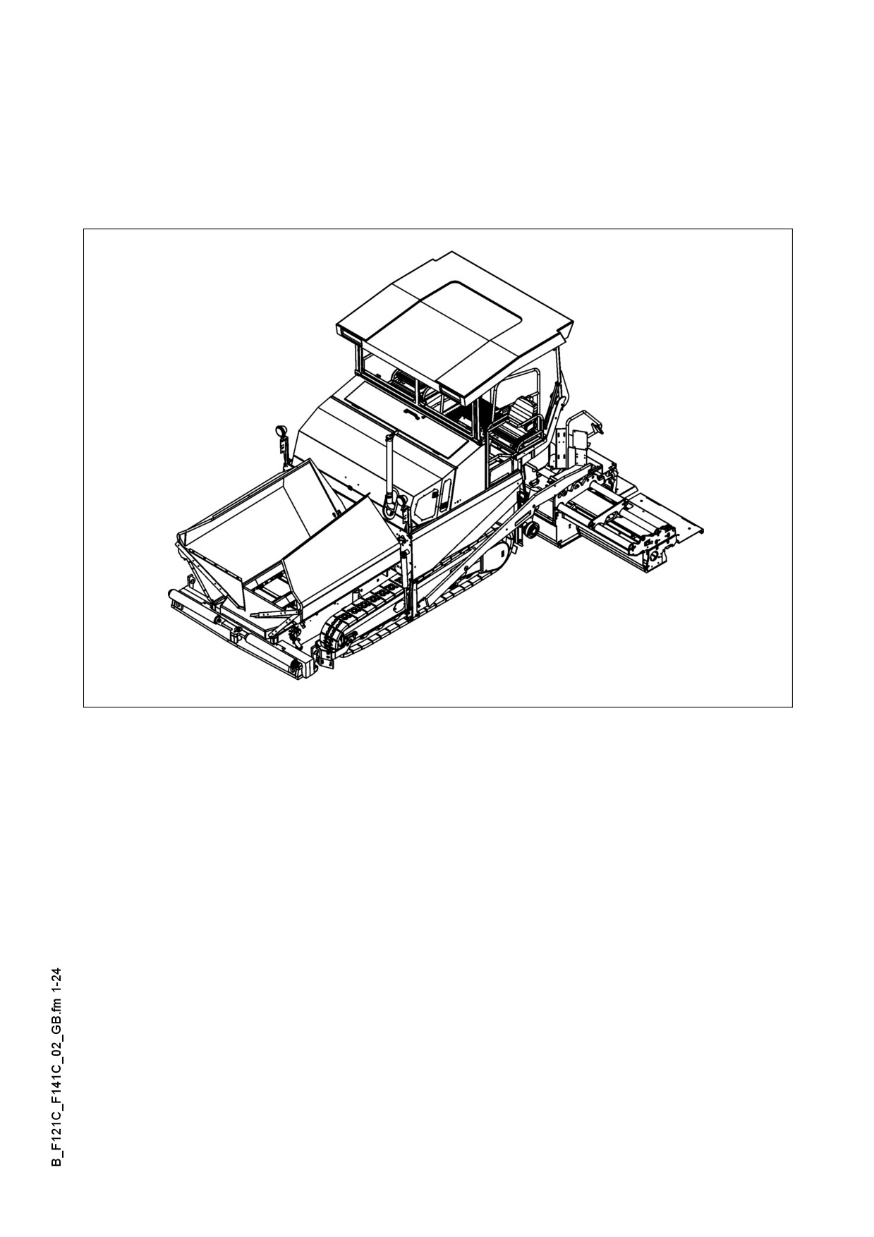
The DYNAPAC F 121 C / F 141 C is a caterpillar paver finisher that is used for laying
bituminous mixed material, roll-down or lean-mixed concrete, track-laying ballast and
unbound mineral aggregates for foundations for paving.
635_ISO_Dyn.bmp
B 1
2
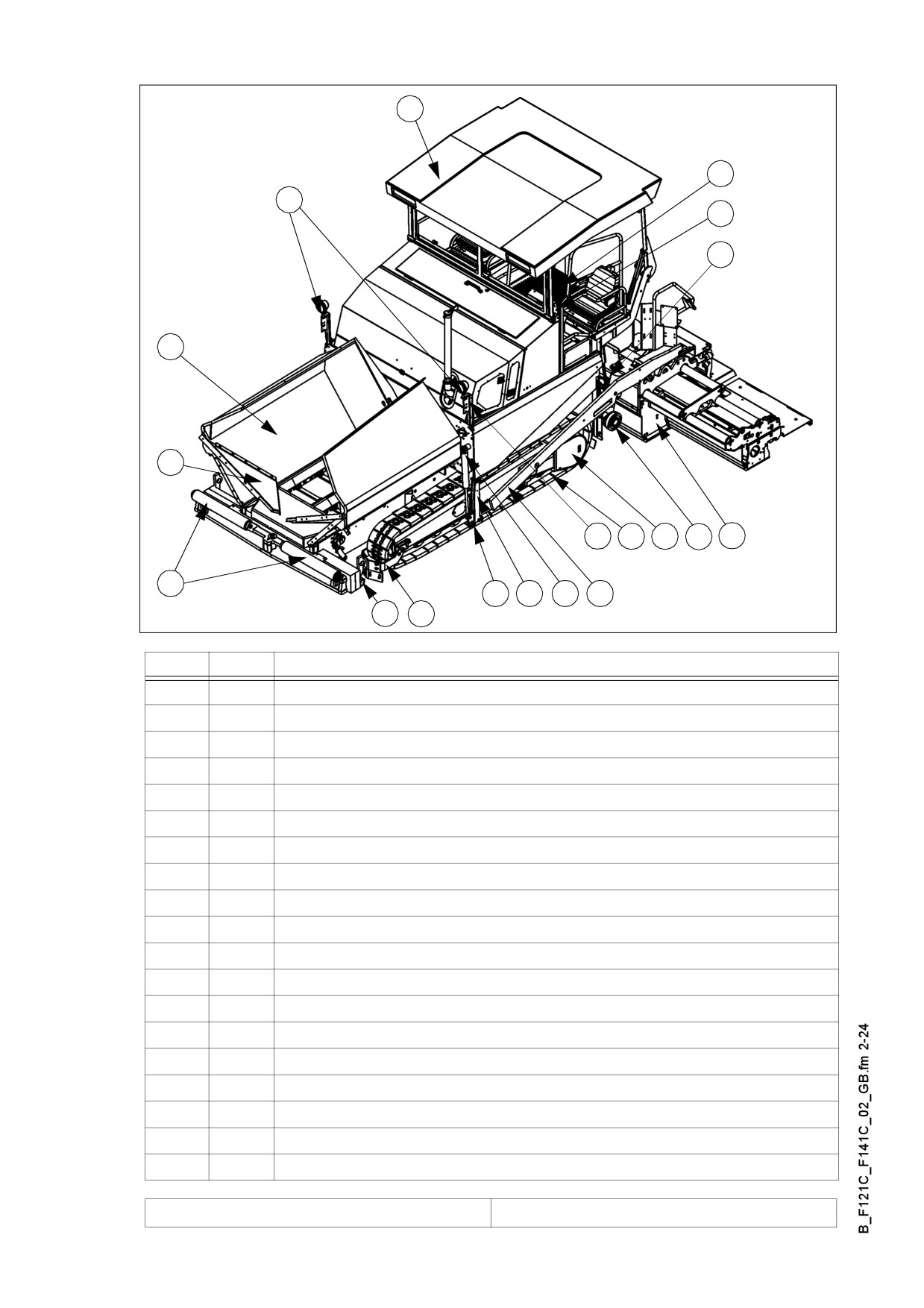
Description of assemblies and functions
15
13
16
14
19
1
18
8
4
10
11
12
2
6
7
5
9
3
17
635_ISO_DYN.bmp
Item
Designation
1
t
Material compartment (hopper)
2
t
Truck push rollers
3
t
Tube for sensor rod (direction indicator) and holder for levelling shoe
4
t
Caterpillar drive
5
t
Levelling cylinder for paving thickness
6
t
Traction roller
7
t
Traction arm rail
8
t
Paving thickness indicator
9
t
Arm
10
t
Traction drive of the caterpillar drive
11
t
Auger
12
t
Screed
13
t
Operator’s platform
14
t
Operating panel (can be moved to either side)
15
o
Protective roof
16
o
Working lights
17
o
Track cleaner
18
o
Hydraulic front hopper lid
19
o
Exhaust of asphalt vapours
t = Standard equipment
o = Optional equipment
B 2
2.1
Vehicle
Construction
The paver finisher has a welded steel frame on which the individual components are
mounted.
The caterpillar drives compensate uneven areas on the ground; the suspension of the
attached screed additionally helps to attain a high paving precision.
The continuously adjustable hydrostatic traction drive allows the speed of the paver
finisher to be matched to all work conditions.
Operation of the paver finisher is faciliated by the automatic material handling system,
the separate traction drives and the clearly structured operating and control elements.
The following extra equipment (option) is available:
o Automatic levelling/slope control system
o Ultrasonic sensors for material transport (controller)
o Additional cut-off shoe
o Larger working widths
o Automatic central lubrication system for the finisher and/or the screed
o Protective roof
o Further equipment and upgrade options on request
Engine: The paver is driven by a water cooled Diesel engine. For further details see
the technical data and the engine's instruction manual.
The particle filter (o) cleans the exhaust gas from the soot particles produced, reduc-
es the generation of harmful carbon-monoxyde and carbon-dioxyde gases, therefore,
it operates as a catalyser to minimize the load on the environment and health. A con-
trol light indicates the necessity of maintenance operations.
Caterpillar drive: Both caterpillar drives are directly driven by separate drives with-
out any drive chains that would require maintenance and servicing.
The tension of the caterpillar chains can be readjusted using tensioners.
Folding track cleaners are mounted before each crawler track (o), which ensure the
flat road section while paving. The minor obstacles found in the track lane are pushed
to the side by the machine.
Hydraulic system: The diesel engine drives the hydraulic pumps for all main drives
of the paver finisher via the attached distribution gear and its auxiliary drive shafts.
B 3
Traction drive: The continuously adjustable traction drive pumps are connected to
the traction motors by means of high pressure hydraulic hoses.
These oil motors drive the caterpillar chains via planetary gears that are mounted di-
rectly inside the drive wheels of the caterpillar chains.
Steering system/operator’s platform: The independent hydrostatic traction drives
allow the finisher to be turned on the spot.
The electronic synchronisation, controlled from the operating panel, ensures that the
finisher runs straight ahead.
The operating panel can be secured in a position at the left-hand or the right-hand
side of the paver finisher by means of a latch accessible from above.
Push roller cross bar: The push rollers for material trucks are fastened to a cross
bar that is pivoted at its center.
This cross bar allows to compensate for different distances to the rear wheels of ma-
terial trucks. The paver finisher thus deviates less from its course and paving in
curves is made easier.
Material compartment (hopper): The hopper inlet is equipped with a conveyor sys-
tem that empties the hopper and transfers the material to the auger.
The hopper can hold about 13.0 t.
To facilitate emptying and to improve material transport, each of the lateral covers of
the hopper can be hydraulically moved (option).
The hydraulic front hopper lids (o) ensure that no material remains at the front of the
feeding hoppers.
Material transfer: The paver finisher is equipped with two conveyors driven sepa-
rately that transfer the material from the hopper to the augers.
By scanning the filling height during the paving procedure, the transfer amount or
speed is regulated fully automatically.
Augers: The augers are driven and actuated independently from the conveyors. The
left-hand and the right hand half of the auger can be controlled separately. The drive
system is fully hydraulic.
The conveying direction can be changed towards the center or towards the outside.
This ensures that there is always a sufficient supply with material even if an excessive
amount of material is required at one side. The auger speed is continuously controlled
by sensors that monitor the material flow.
Height adjustment and extension of augers: Height adjustment and extension of
augers ensure optimum adaptation to a wide range of paving thicknesses and widths.
The basic configuration allows the height to be adjusted by attaching chains to the
side arms and by actuating the hydraulic screed lifting device.
When using ratchets for height adjustment (option), barrel nuts at the guide supports
in the rear wall are used to adjust the height.
Another variant allows the height to be regulated at the control panel by means of hy-
draulic cylinders (option).
Auger segments of different lengths can be attached to easily adapt to the different
paving widths.
B 4
Levelling system/slope control system: The slope control system (option) allows
the traction point to be regulated at the left-hand or the right-hand side with a defined
difference to the opposite side.
To determine the actual value, the two traction arms are linked with a slope control
rod.
The slope control system always operates in conjunction with the screed height ad-
justment of the opposite side.
By adjusting the height of the traction point of the arm (traction roller), the paving
height of the material or the laying height of the screed can be controlled.
Actuation occurs electro-hydraulically on both sides and can be controlled manually
by means of toggle switches or automatically by means of an electronic grade control
system.
The screed lifting system: The screed can be lifted to transport height using the
screed lifting system. Lifting occurs electro-hydraulically on both sides by actuating
the hydraulic cylinders on the arms and is controlled by means of toggle switches on
the operating panel.
Automatic screed stop and screed charging/relieving device: The automatic
screed stop prevents the screed marks caused by a stopped screed. When the paver
is stopped (changing trucks), the screed remains in floating position and the relieving
pressure is turned on, therefore, the sinking of the screed can be avoided while
stopped.
The screed relieving device puts a higher load on the chassis, thus increasing the
traction.
Activating the screed charging device can improve the compacting result under cer-
tain conditions.
Exhaust of asphalt vapours (o): The asphalt vapours are extracted by a hydrauli-
cally driven exhaust head mounted in the material tunnel or over the auger. The va-
pours collected are discharged together with the exhaust fumes of the internal
combustion engine.
Central lubrication unit (o): The central lubrication pump fitted with a large lubricant
tank supplies grease to the various lubrication circuits through various flow dividers.
They supply lubricant to the service-sensitive points of lubrication (e.g. bearings) by
adjustable intervals.
B 5
3
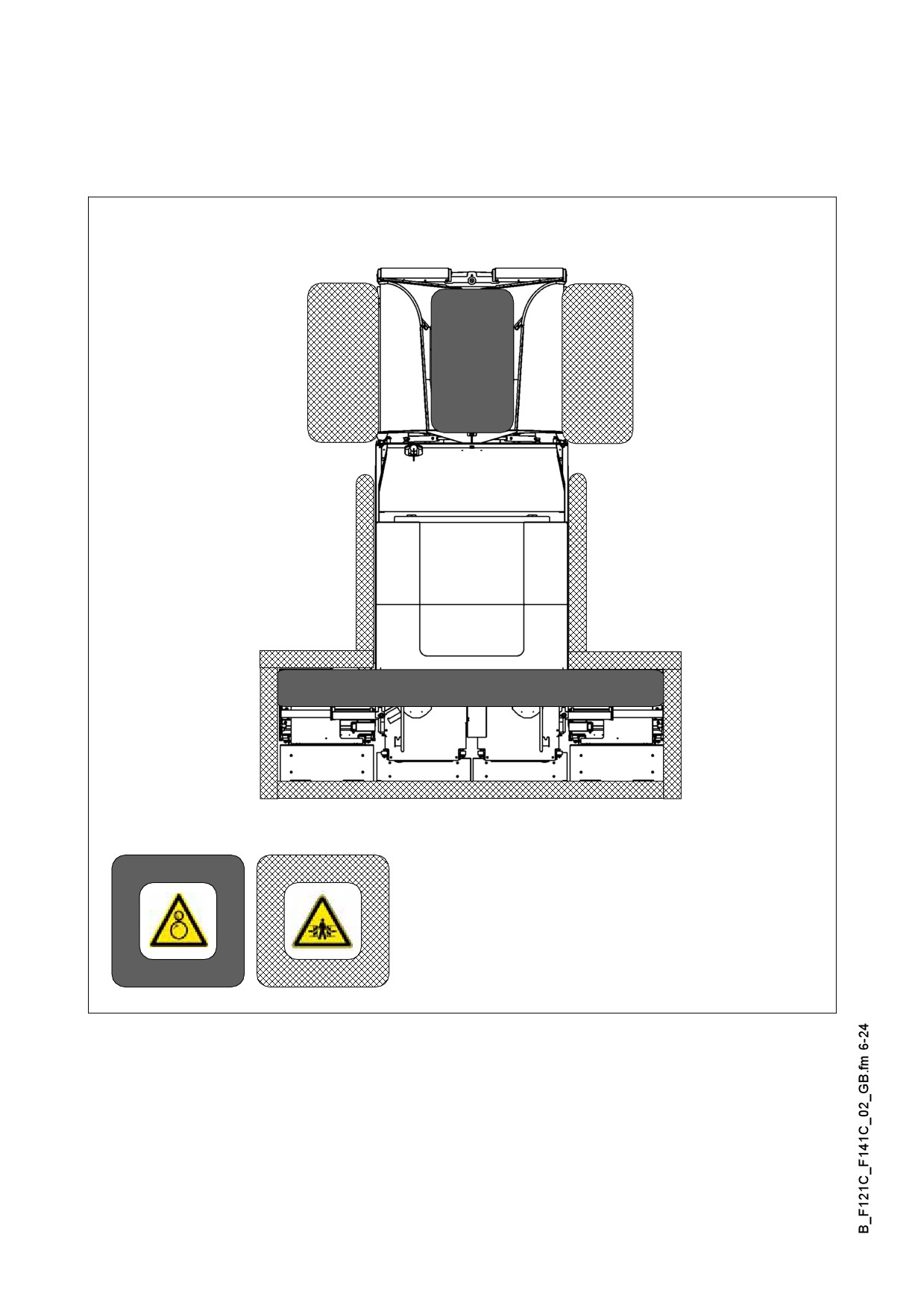
Danger zones
m In these areas of the machine there is a danger of pulling in or crushing due to the
rotating, transporting or moving parts!
B 6

4
Safety devices
Safe operation is only possible when all operating and control elements are function-
ing correctly and when all safety devices are in position.
A Check the function of these devices at regular intervals.
(see chapter D, section 2.1).
4.1
Emergency stop button
- on the operating panel
- on the two remote control units
F0005_A1.EPS
(option)
m Pressing the emergency stop button switches off the engine, the drives and the steer-
ing system. Corrective measures that might be necessary (anti-collision maneuvers,
lifting the screed, etc.) are not possible in this case! Danger!
4.2
Steering system
F0069_A1.EPS
4.3
Horn
- on the operating panel
- on the two remote control units
Horn.Tif
(option)
4.4
Ignition key / lights
F0064_A1.EPS
B 7
4.5
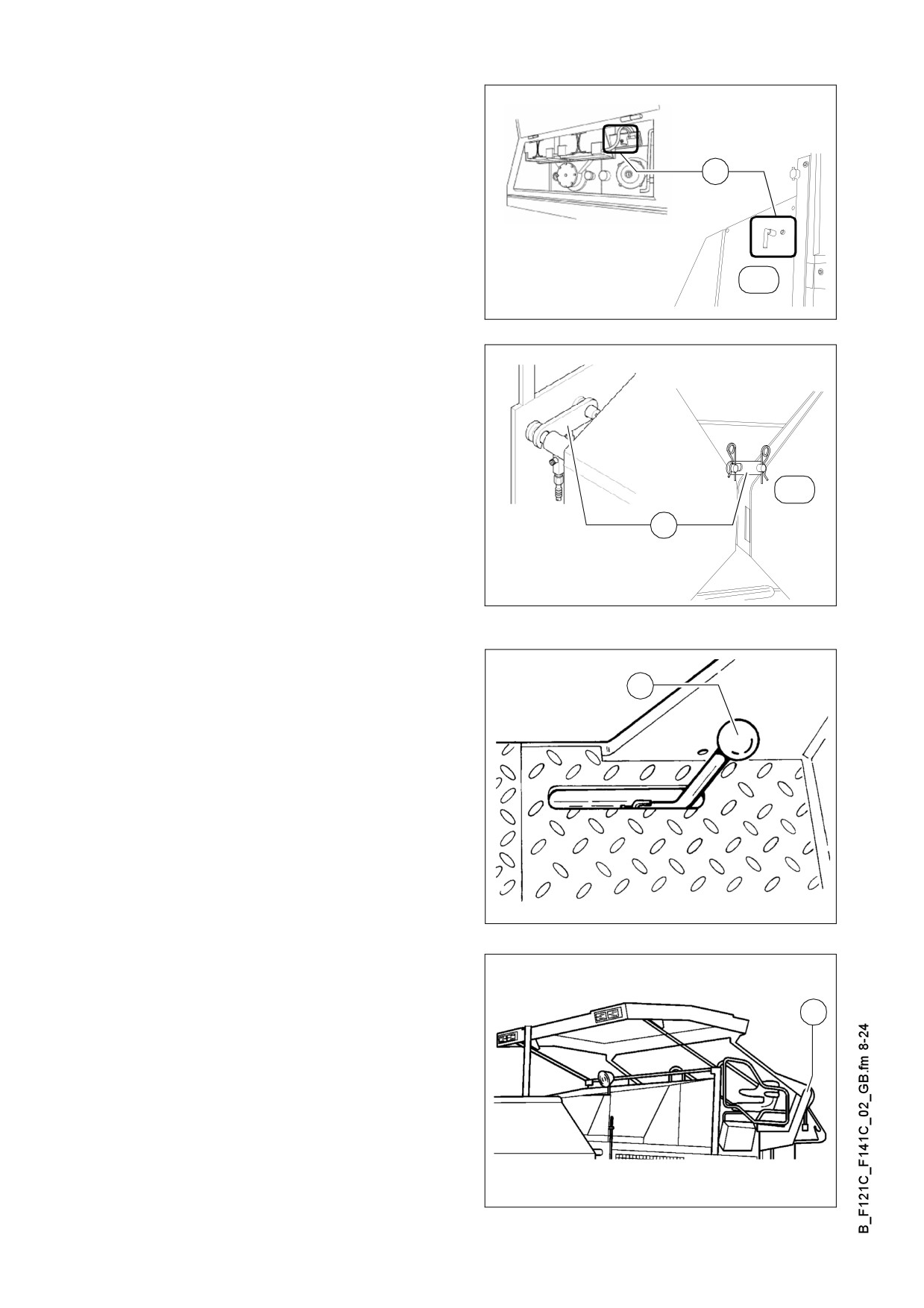
Main switch (17)
17
(o)
Mainswitch.tif/Mainswitch_SK.eps
4.6
Hopper transport safeguards (18)
(o)
18
Hopperlock2.tif/Hopperlock_SK.eps
4.7
Screed transport safeguard (19)
19
F0083_A1.TIF
4.8
Latch for protective roof (20)
20
F121Cb.Tif
B 8
26
27
25
30
31
29
28
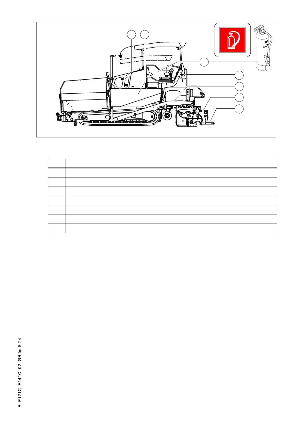
635_side_Dyn.bmp/Feuerlöscher.bmp
Item
Designation
25
Fire fighting device
26
Engine hood
27
Lateral flaps
28
Walkway
29
Screed coverings
30
Hazard warning lights of the screed
31
Auger covers
Accessories:
- Wedges
- Warning triangle
- First-aid kit
B 9
5
Technical data, standard configuration
5.1
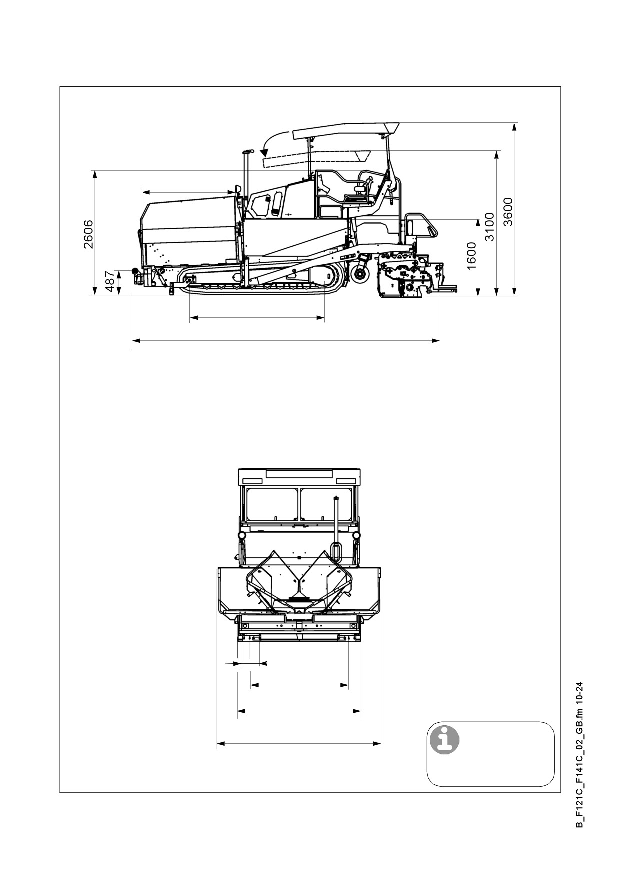
Dimensions (all dimensions in mm)
1979
2900
6505*
305
1988
2550
3388
*VB510 T/TV
635_side_DYN.bmp,635_front_DYN.bmp
A For the technical data of the screed, see the operating instructions of the screed.
B 10
5.2
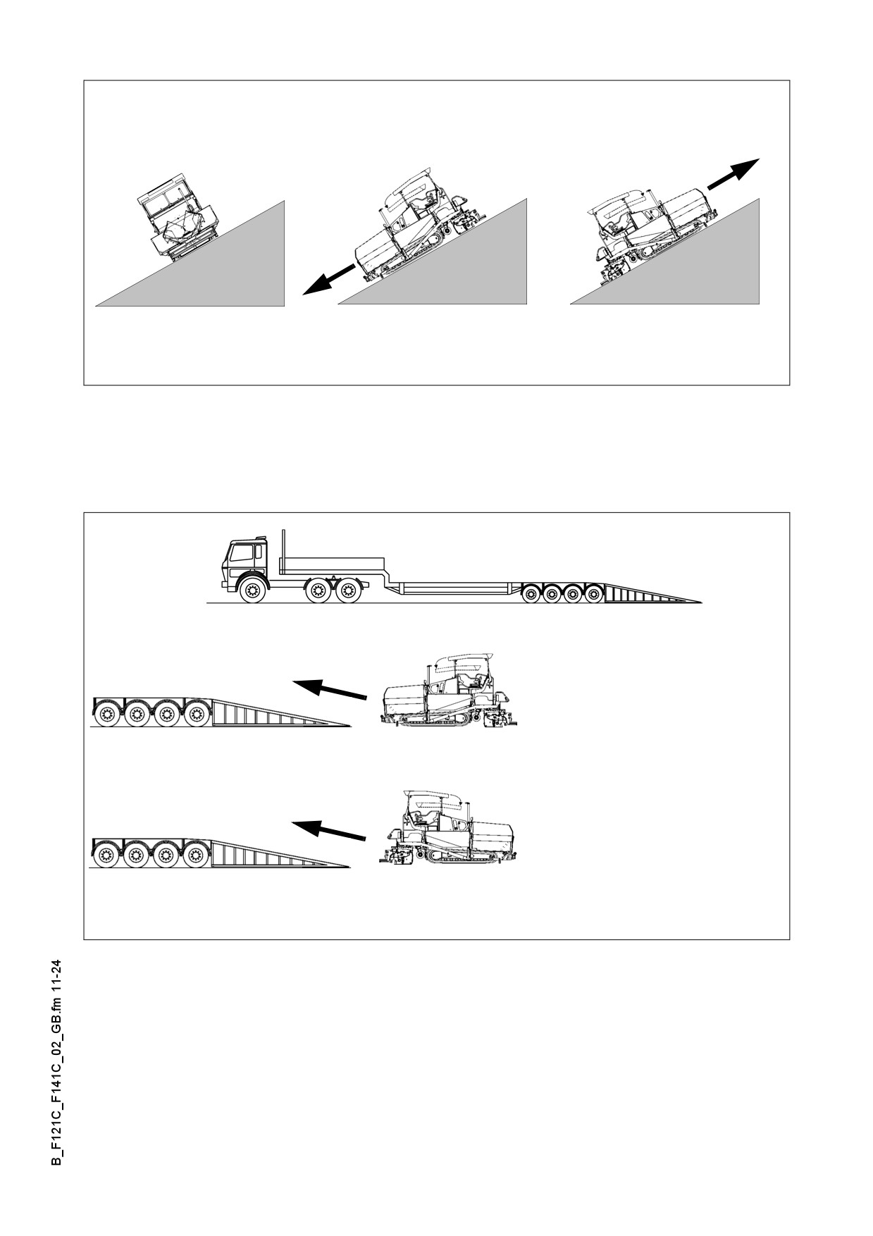
Allowed angle of rise and slope
max 15°
max 15°
max 15°
635_side_Dyn.bmp,635_front_Dyn.bmp
A Before operating your machine in an inclined position (gradient, slope, lateral inclina-
tion) which is above the specified limit value, please, consult with the customer serv-
ice for your machine!
5.3
Allowed angle of driving up
max 14°
max 14.4°
635_side_Dyn.bmp,635_front_Dyn.bmp
B 11

5.4
Weights F 121 C (all weights in t)
Paver finisher without screed
about 16,3
Paver finisher with screed:
- VB510 T/TV
about 18,2
With extensions for max. working
about 1,4
width additionally max.
With filled hopper
about 13,0
additionally max.
For the weights of the screed and the screed attachments, see the operating instruc-
A
tions for the screed.
5.5
Weights F 141 C (all weights in t)
Paver finisher without screed
about 16,6
Paver finisher with screed:
- VB510 T/TV
about 18,5
Including mounted accessories
for max. paving width
about 1,4
additionally max.
With filled hopper
about 13,0
additionally max.
For the weights of the screed and the screed attachments, see the operating instruc-
A
tions for the screed.
B 12

5.6
Performance data F 121 C
VB 510 T/TV
2,55
2,00
5,10
8,10
m
VB 510 T/TV+
2,55
2,00
5,10
m
VB 600 T/TV
3,00
2,45
6,00
8,20
m
VB 600 T/TV+
3,00
2,45
6,00
m
SB 1250 T/TV
3,00
*
m
Travelling speed
0 - 4,5
km/h
Working speed
0 - 23
m/min
Layer thickness
0 - 300
mm
Max. grain size
40
mm
Theoretical paving performance
600
t/h
B 13

5.7
Performance data F 141 C
VB 510 T/TV
2,55
2,00
5,10
8,80
m
VB 510 T/TV+
2,55
2,00
5,10
m
VB 600 T/TV
3,00
2,45
6,00
9,00
m
VB 600 T/TV+
3,00
2,45
6,00
m
SB 1250 T/TV
3,00
9,00*
m
Travelling speed
0 - 4,5
km/h
Working speed
0 - 23
m/min
Layer thickness
0 - 300
mm
Max. grain size
40
mm
Theoretical paving performance
750
t/h
B 14

5.8
Traction drive/chassis
Hydrostatic drive,
Drive
continuously controllable
Two separately driven caterpillar drives with rub-
Caterpillar drive
ber grouser chains.
Turning capacity
Turning on the spot
Speed
See above
5.9
Engine F 121 C
Make/type
Deutz TCD 2012 L06 2V
Model
6-cylinder diesel engine (water-cooled)
Performance
120 KW / 163 HP (at 1800 rpm)
Volume of fuel tank
(see chapter F)
5.10
Engine F 141 C
Make/type
Deutz TCD 2013 L06 2V
Model
6-cylinder diesel engine (water-cooled)
Performance
140 KW / 190 HP (at 1800 rpm)
Volume of fuel tank
(see chapter F)
5.11
Hydraulic system
Hydraulic pumps via distribution gear
Pressure generation
(directly flanged to the engine)
Hydraulic circuits for:
- Traction drive
- Material conveying and distribution
- Screed lifting drives for tamper / vibration
Pressure distribution
(option)
- Cylinder actuators for steering, hopper,
levelling, screed lifting, extending/retracting
screed parts, auger lift (option)
Hydraulic oil reservoir - volume
(see chapter F)
B 15

5.12
Material compartment (hopper)
Volume
about 6.0 m3 = about 13.0 t
Minimum inlet height, center
520 mm
Minimum inlet height, outside
595 mm
5.13
Material conveying
Conveyors
Left and right auger separately controllable
Drive
Hydrostatic, continuously controllable
Conveying volume controller
Fully automatic via configurable switching points
5.14
Material distribution
Augers
Left and right auger separately controllable
Hydrostatic external drive, continuously controlla-
ble
Drive
independent from the conveyor
Auger halves can be switched to opposite direc-
tions
Conveying volume controller
Fully automatic via configurable switching points
- mechanically via chain
Auger height adjustment
- mechanically (option)
- hydraulically (option)
Auger extension
With extension parts (see auger extension chart)
B 16
5.15
Screed lifting device
At standstill:
- Screed stop
- Screed stop with pretensioning
(max. pressure 50 bar)
Special functions
During paving:
- Screed charging
- Screed relieving
(max. pressure 50 bar)
Mechanical grade control,
Levelling system
optional systems with and without
slope control
5.16
Electrical system
On-board voltage
24 V
Batteries
2 x 12 V, 100 Ah
17 kVA / 400 V
Alternator (o)
20 kVA / 400 V
28 kVA / 400 V
Fuses
see chapter F, section 5
A For the filling volumes of lubricating and operating agents, see chapter F,
B 17
6
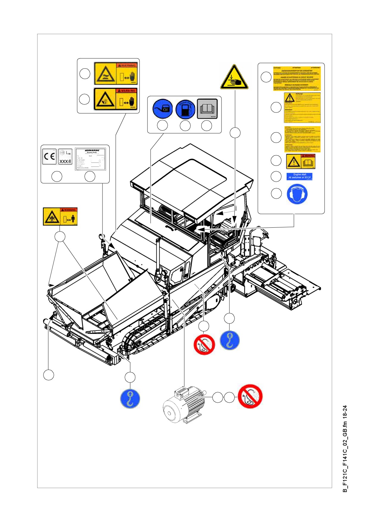
Location of instruction labels and identification plates
9
12
8
14
1
2
3
17
13
11
7
6
15
16
4
5
10
18
5
10
(o)
B 18

Item
Designation
1
Label ”Filler neck for diesel fuel” *
2
Label ”Filler neck for engine oil” *
3
Label „Heed the operating instructions!“
4
Warning label ”Danger of squeezing!” **
5
Punched vehicle identification number
6
Label ”Securing or fixing points for crane transportation” **
7
Paver finisher identification label
8
„CE + noise level“ plate (O)
9
„Fan danger!“ warning plate
10
„Spraying with water prohibited“ plate
11
Label „Heed the operating instructions!“ ***
12
Label ”High voltage!”
13
Label ”Operating instructions for the engine”
14
„Crossbeam lock“ plate
15
„All switches to STOP“ plate ***
16
Label „Wear Ear Mufflers“
17
Label „Risk of hand injury“
18
Punched vehicle identification number
Labels are located beneath the engine hood / maintenance flap
**
Labels are located on both sides of the paver finisher
***
Label is located on the operating panel, above the steering wheel
B 19

6.1
Identification label for the paver finisher (6)
1
2
3
4
5
6
7
8
Fertiger3.tif
Item
Designation
1
Type of paver finisher
2
Year of manufacture
3
Serial number of the paver finisher series
4
Max. permissible operating weight, incl. all attachments, in kg
5
Max. permissible load on the front axle, in kg
6
Max. permissible load on the rear axle, in kg
7
Rated performance in kW
8
Product identification number (PIN)
The punched vehicle identification number on the paver finisher must match the prod-
A
uct identification number (8).
B 20
//////////////////////////////////////////