DYNAPAC Paver finisher F 121 C, F 141 C Type 635. Operation & Maintenance (Order number: 4812026925) - page 3
Item
Designation
Brief description
m It is on, when the oil pressure is too low.
Stop the engine again.
Oil pressure indica-
See the further possible faults in the operating in-
47
tor for the Diesel en-
structions for the engine
gine (red)
A The fault is indicated together with the „Error mes-
sage“ light.
48
Not used
Battery charge indi-
Must go out after starting when the engine revs up.
49
cator (red)
- Switch off the engine.
50
Not used
51
Fuse box I.
A For assignment of fuse strips, refer to chapter F.
52
Fuse box II.
A For assignment of fuse strips, refer to chapter F.
D 1.1 23
3
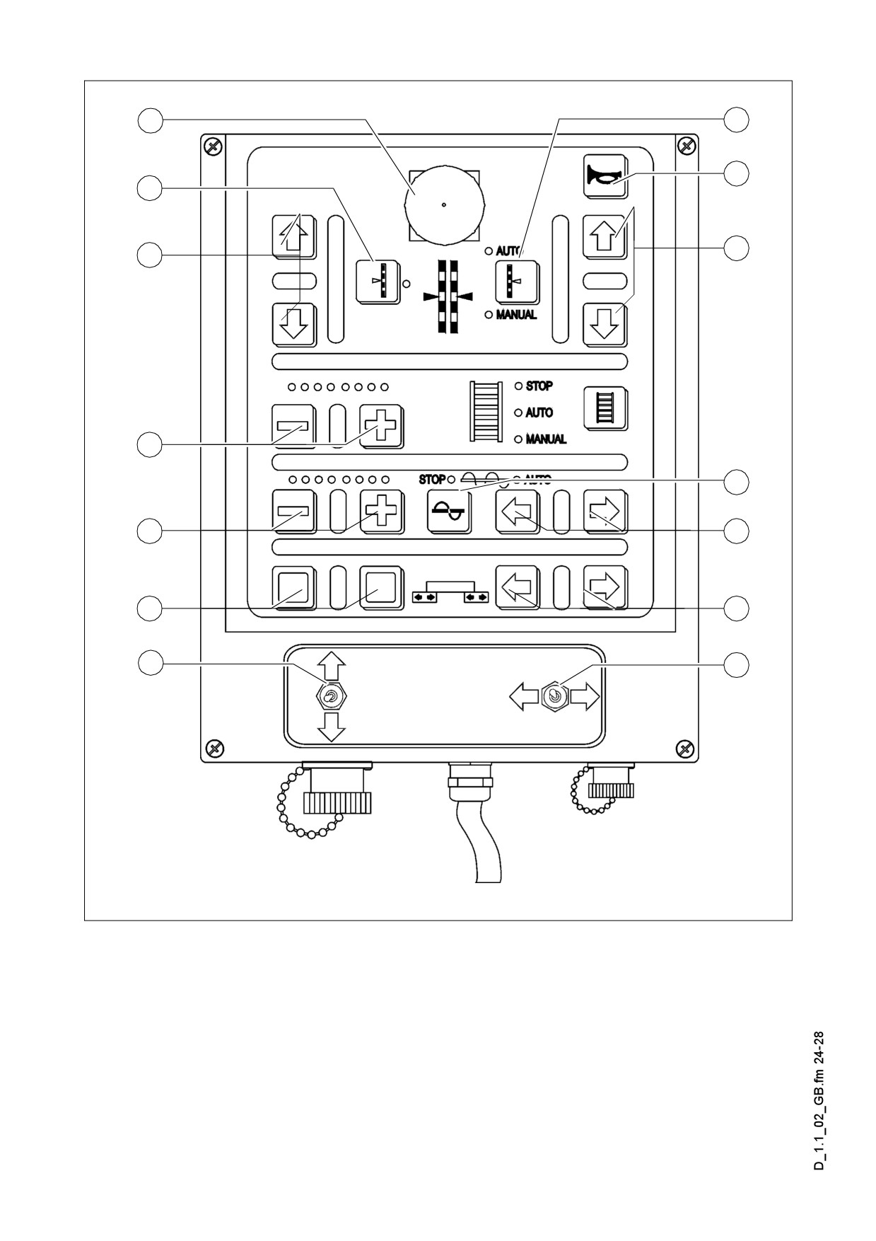
Remote control
54
56
55
57
58
58
60
61
63
62
65
64
67
66
m Warning! Do not isolate while operating by remote control provided with emergency
stopping button (0). This will lead to stopping the machine!
D 1.1 24

Item
Designation
Brief description
Its function and use are similar to those of the emergency
Emergency stop
button (7) on the control panel.
54
button (o)
It is important in such dangerous situations, which cannot be
overseen by the driver.
55
Horn
Its function is similar to the button (30) on the control panel.
Its function and use are similar to the function of the button
56
Levelling cylinder
(25) on the control panel.
- The switch must be set to „manual“ position.
The button of adjust-
It allows the operation of the levelling cylinder on the other
57
ing the leveller on
side of the paver finisher. The display of the other remote
the other side.
control automatically switches to „manual“ position.
Buttons of move-
58
Its function is similar to the button (27) on the control panel.
ment directions
59
Feeder
Its function is similar to the button (32) on the control panel.
Plus / minus buttons for the modification of transport capaci-
Capacity of feeder
60
ty. Indicated by LEDs. The modifications are saved in „auto“
and LED display
position by button (59).
If the function (56) was set to position „auto“, when pressing buttons (58) it will revert
A
to „manual“ mode.
D 1.1 25
54
56
55
57
58
58
60
61
63
62
65
64
67
66
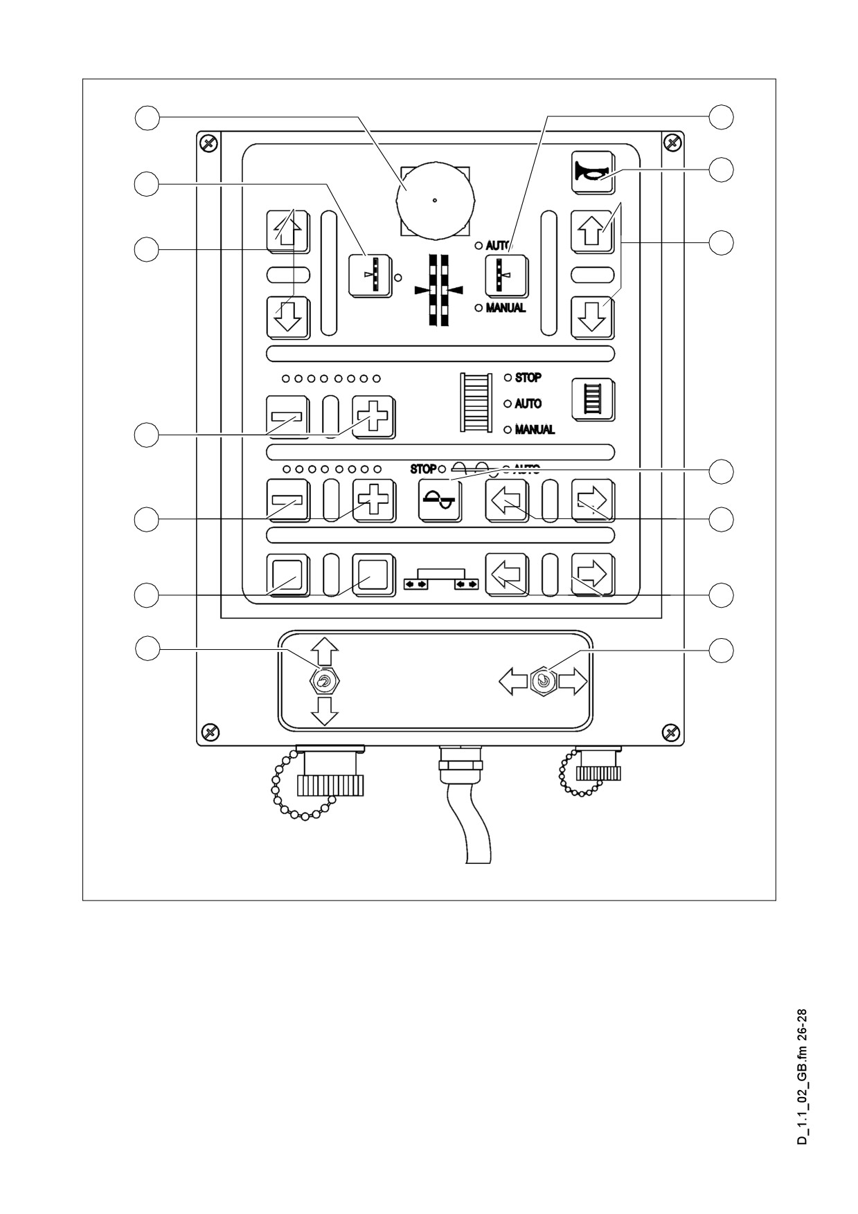
m Warning! Do not isolate while operating by remote control provided with emergency
stopping button (0). This will lead to stopping the machine!
D 1.1 26
Item
Designation
Brief description
61
Auger
Its function is similar to the button (24) on the control panel.
Conveying direction
For the adjustment of the transport direction of the auger
62
of the auger.
- switch (61) must be set to „auto“.
Transport capacity
Plus / minus buttons for the modification of transport capaci-
63
of the auger and
ty. Indicated by LEDs. The modifications are saved in „auto“
LED display
position by button (61).
Screed extension/
With these buttons the screed can be moved in the directions
64
retraction
indicated by the arrows.
65
has no function
Extending / retract-
Use these buttons to move the screed in the direction indicat-
66
ing screed(o)
ed by the arrow.
For manually actuating the levelling cylinders when automat-
Levelling cylinder
67
ic levelling is switched off.
left/right (o)
This function must be switched to Manual.
If the function (61) was set to position „stop“, when pressing buttons (62) it will
A
change to „auto“ mode.
Basic setting of the delivery capacity of the auger and the feeder, with respect to the
A
various types of courses (number of LEDs):
- Top layer: 4
- Binder course 6
- Load bearing course: 8
D 1.1 27
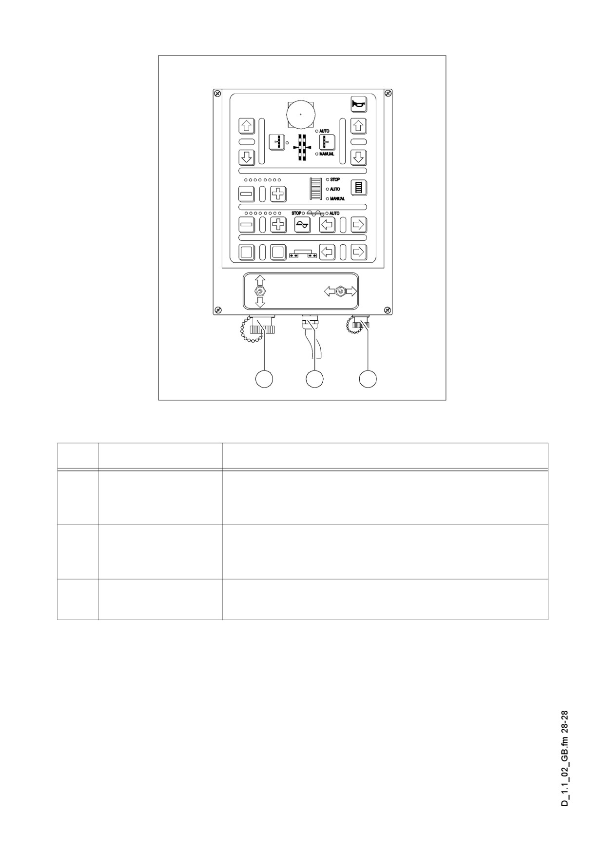
Bottom part
68
70
69
Remote_SPS_neu2.bmp
Item
Designation
Brief description
Connection to the
68
levelling automatic
Connect the cable for the grade control unit here.
system
Connection to the
69
end position switch of
Connect the cable for the material limit switch here.
the auger
Cable for the remote
Connect to the socket on the screed.
70
control
(See operating instructions for the screed).
D 1.1 28
D 2.0
Operation
1
Operation of the input and display terminal
D
C
B
A
TDM.cdr
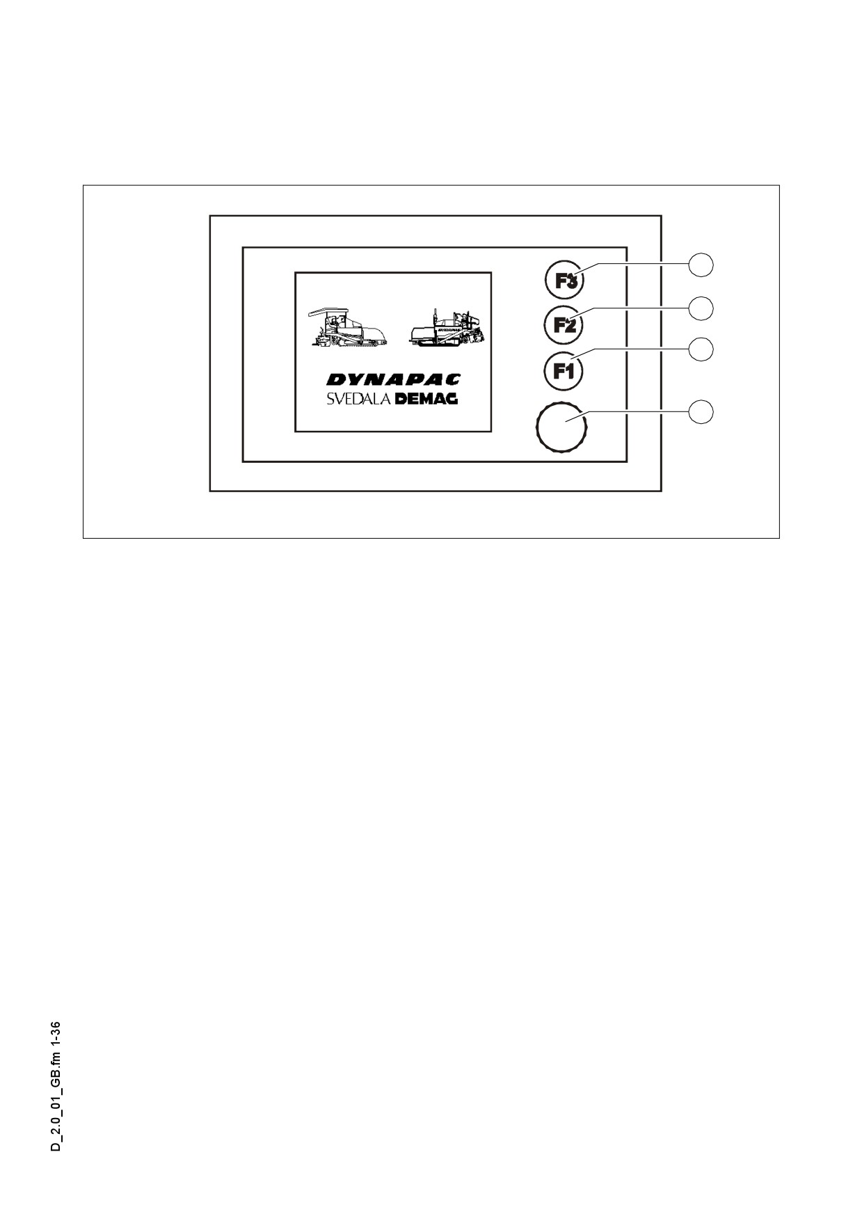
Allocation of the keyboard of the display.
-
(A) Encoder (Rotation and pressure):
- For paging in the menu
- For selecting various points within one menu
- For the modification of parameters
- For confirming the modified parameters
- Buttons (B), (C), (D) F1 - F3:
- To select the functions displayed on the screen
- For selecting various points within one menu
- For the modification of parameters
D 2.0 1
1.1
Working in the menu
1
D
C
B
A
TDM.cdr
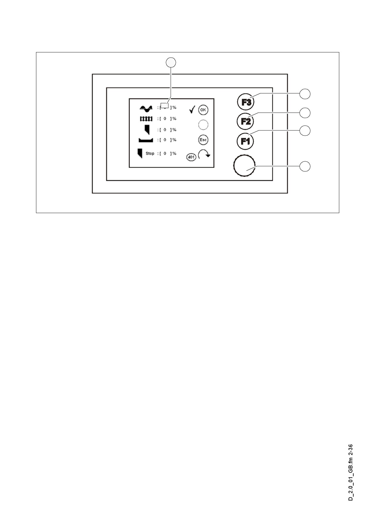
Example: Emergency program (401)
- Rotate (A) Encoder until the selection surface (1) appears.
- Rotate Encoder (A) until the selection surface gets on the menu point required.
- Press (A) Encoder or (B) F2 button to modify the selected menu point.
- Adjust the required value by rotating Encoder (A).
- Press (A) Encoder or (B) F2 button to confirm the set value.
A In the various menus the parameters can be modified directly, without highlighting
them with the selection surface!
D 2.0 2
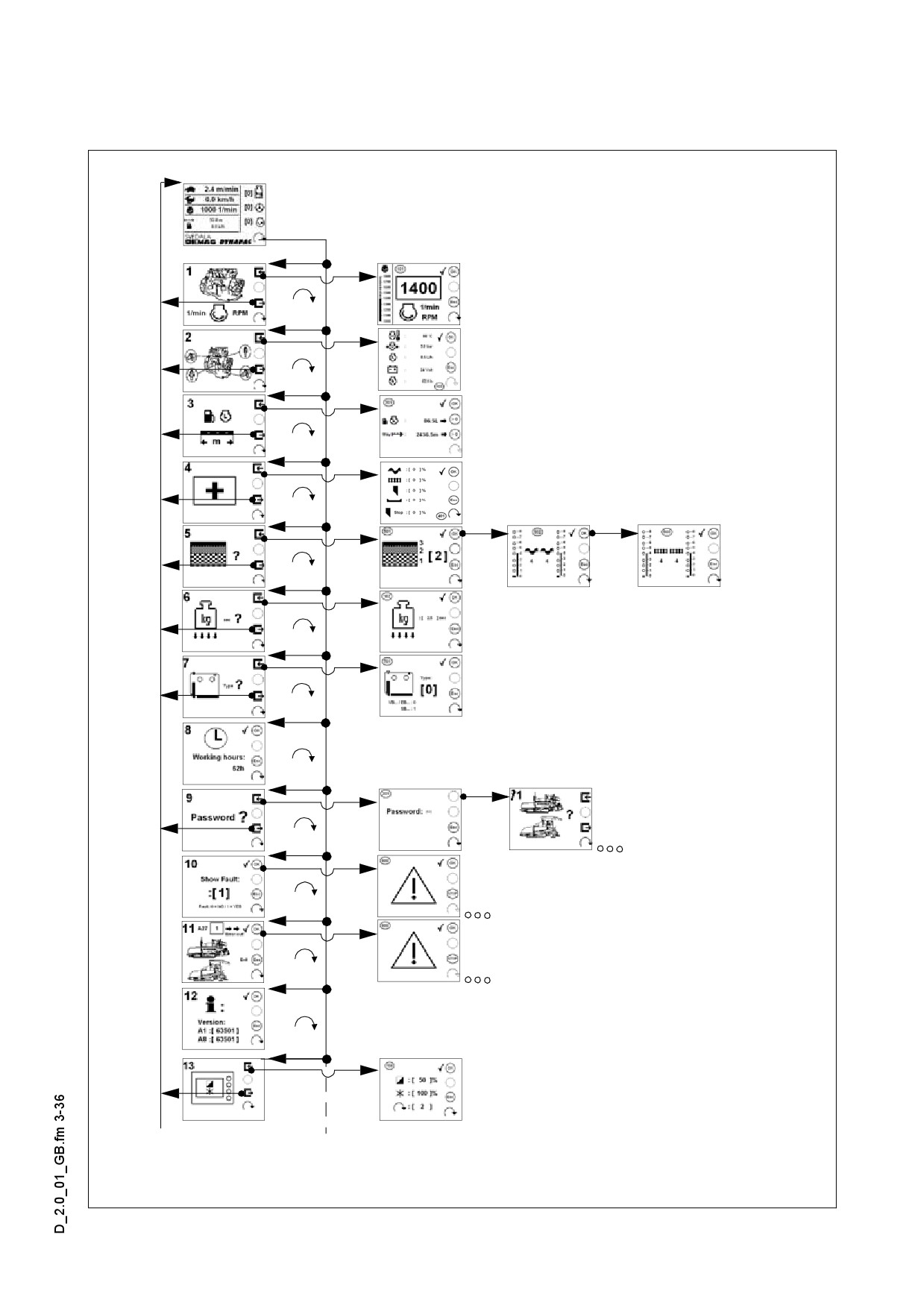
Menu structure of the setting and display options
The following figure shows the menu structure and operation and it serves the simpli-
fication of the procedures in case of various settings and displays.
D 2.0 3
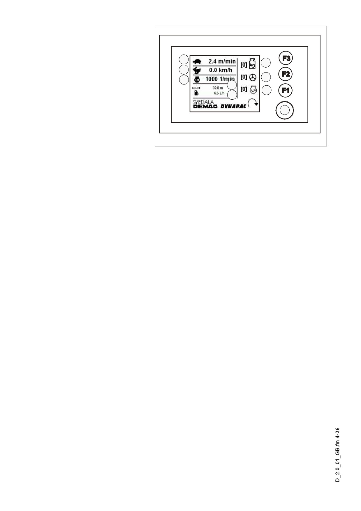
Main menu 00
Display and function menu
1
6
- Speed - processing mode
2
7
(1)
3
4
- Speed - Travel (2)
8
5
- Engine speed (3)
- Road length meter (4)
9
- Fuel consumption (5)
- Adjustment possibility
„Stopping the screed with
Terminal_SPS_Kette_635.wmf/Bild_000.bmp
pretensioning“ (6)
- 0=The function is inactive
- 1=The function is active
When the drive lever is in neutral position, the screed retains its position with the
A
pressurization of the appropriate cylinder and so the sinking of the screed into the
laid material can be avoided.
- Adjustment possibilities of „Steering Automatic System“ (7)
- 0=The function is inactive
- 1=The function is active
- Drive engine in „Eco-mode“ (8)
- The engine speed is regulated to permanent 1600 rpm.
- Open submenu (101) (9)
In case of activated steering automatic system the steering potentiometer is OFF.
A
Steering is automatic, by sensing the Ski-string.
D 2.0 4
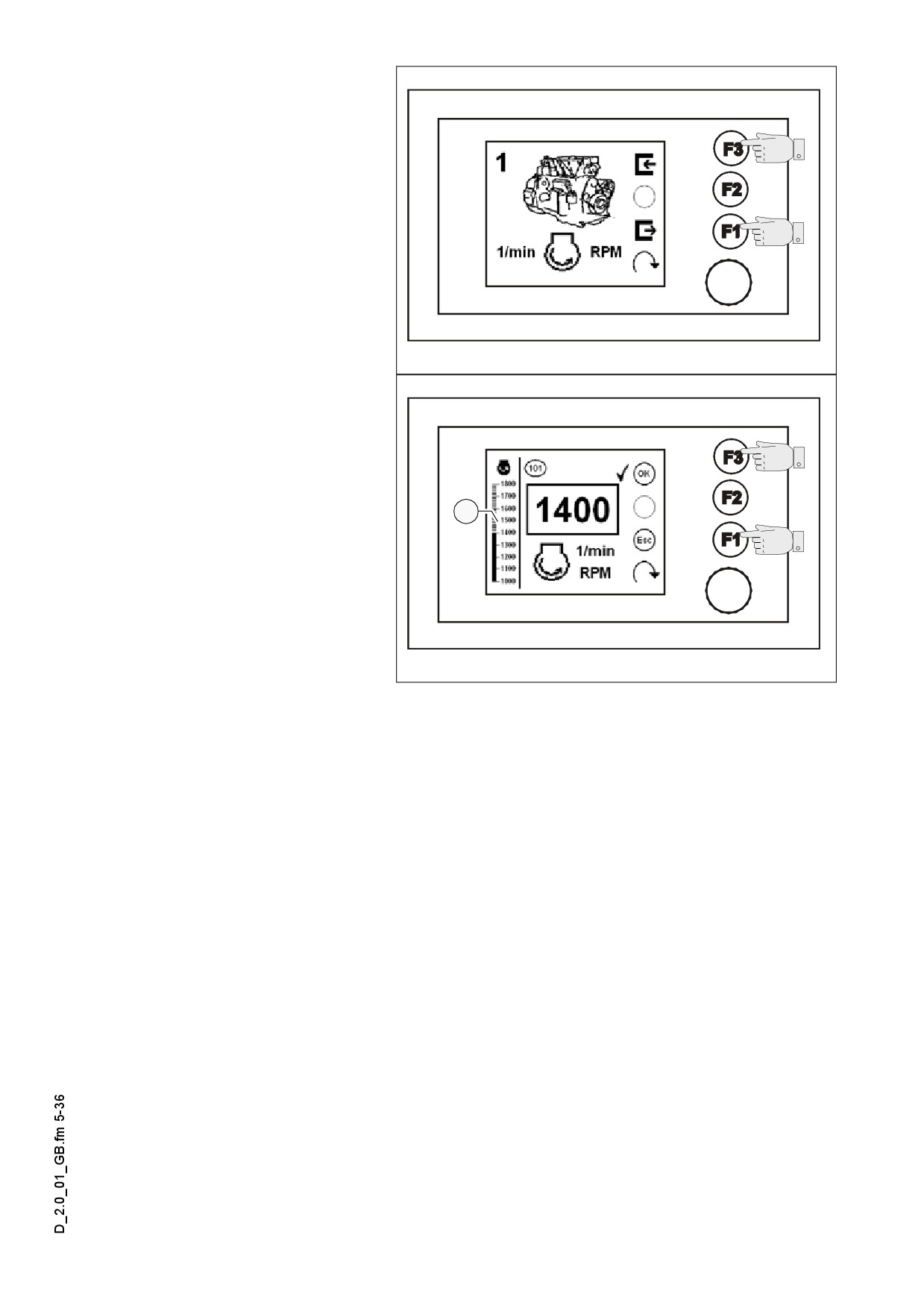
Menu 01 - Engine speed
Adjustment menu of engine
speed (1)
- Open the submenu: F3).
- Back to the main menu:
(F1)
Terminal_SPS_Kette_635.wmf/Bild_000.bmp
Submenu 101 - Setting the
engine speed
- Saving, back to the main
menu: (F3)
- Resetting changes, back to
the main menu: (F1)
1
A Setting is performed in steps
of 50, the speed of the en-
gine directly follows the ad-
justments.
Terminal_SPS_Kette_635.wmf/Bild_000.bmp
A Illustration of engine speed
by column diagram (1).
D 2.0 5
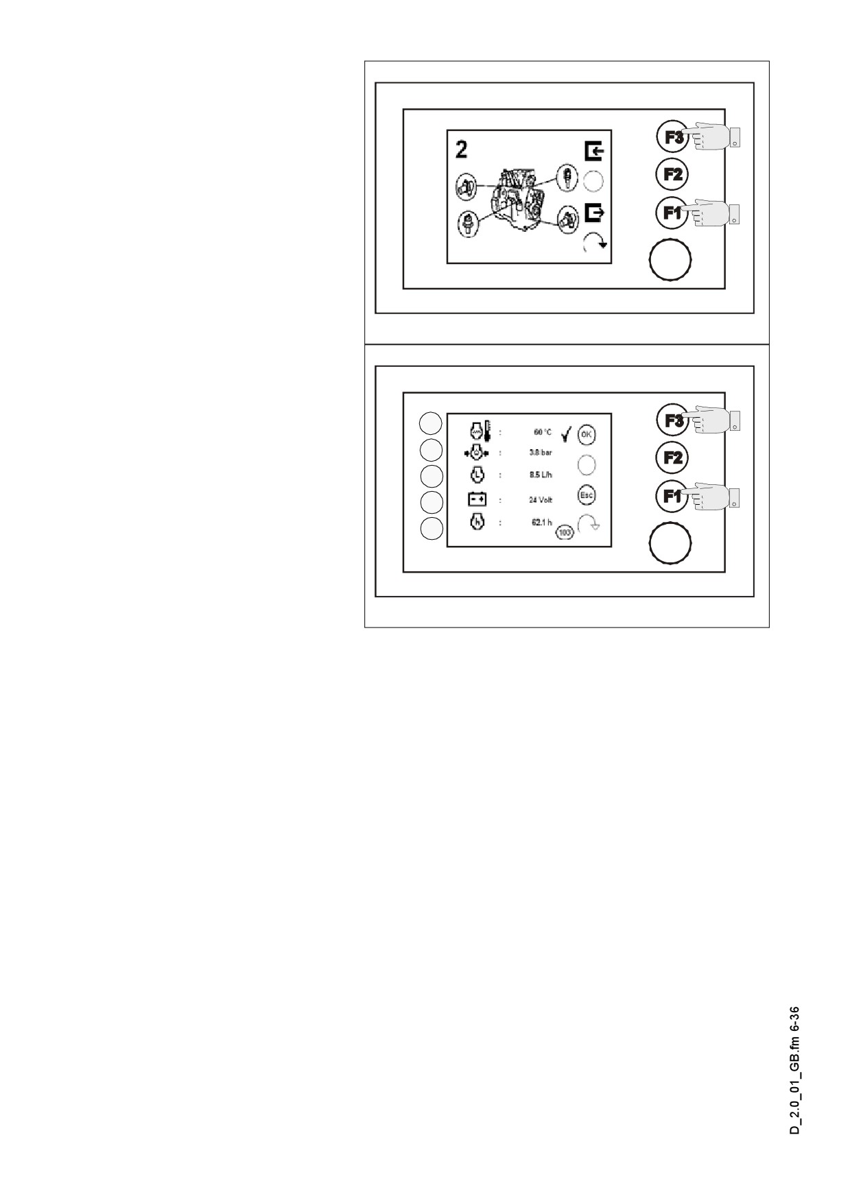
Menu 02 - Measuring value
of drive engine
Menu to query the various
measuring values of the drive
engine.
- Open the submenu: (F3)
- Back to the main menu:
(F1)
Terminal_SPS_Kette_635.wmf/Bild_000.bmp
Submenu 103 - Display of
measuring value Drive en-
gine
1
Display of the following
measuring values:
2
3
- Engine temperature (1)
4
- Engine oil pressure (2)
5
- Fuel consumption (3)
- Battery voltage (4)
- Number of engine service
hours (5)
Terminal_SPS_Kette_635.wmf/Bild_103.bmp
- Back to menu 02: (F1), (F3)
D 2.0 6
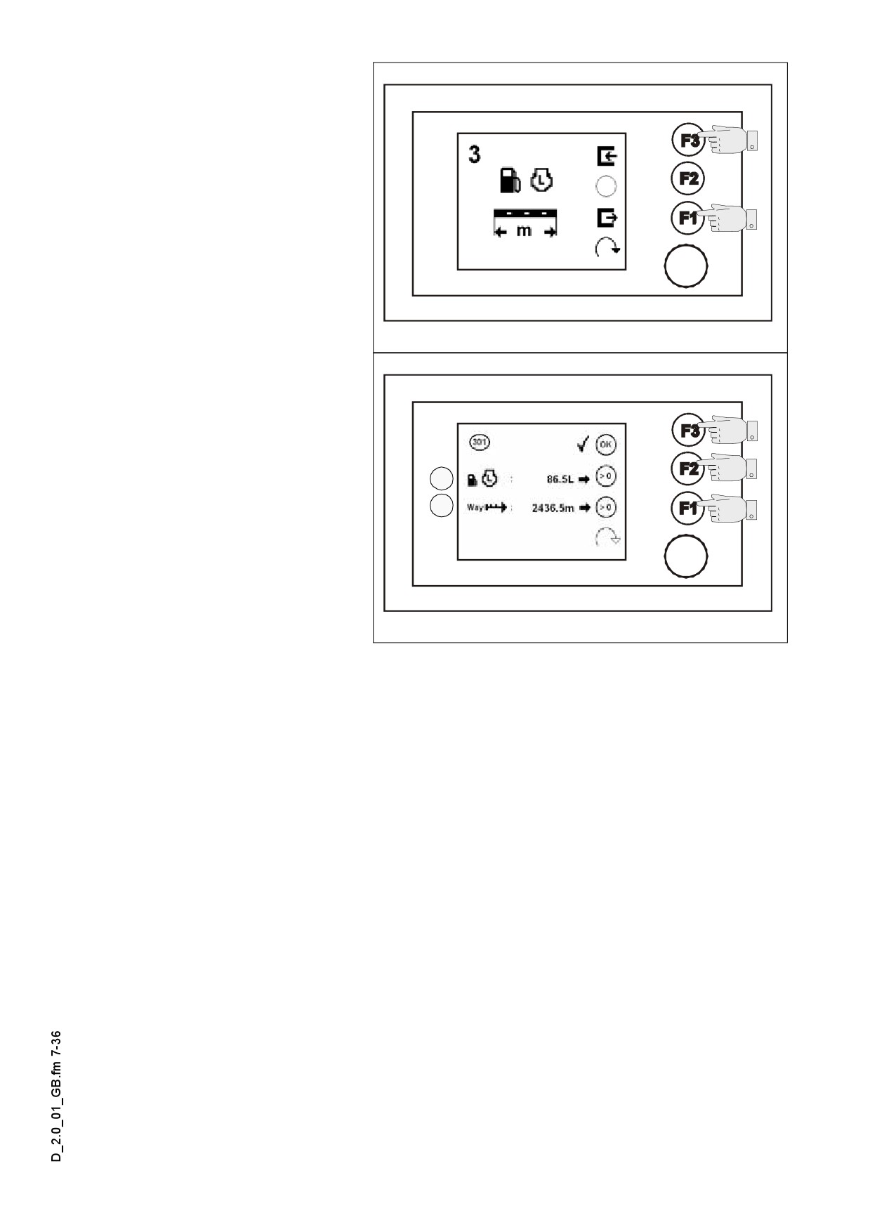
Menu 03 - Trip meter and
fuel gauge
Menu to query the various op-
erating data
- Open the submenu: (F3)
- Back to the main menu:
(F1)
Terminal_SPS_Kette_635.wmf/Bild_003.bmp
Submenu 301 - Road sec-
tion, fuel consumption dis-
play/reset
Display of the following serv-
ice data:
1
- Fuel consumed
2
(calculated value) (1)
- Reset - setting the value
to zero, step back
Menu 03: (F2)
- Trip covered (2)
Terminal_SPS_Kette_635.wmf/Bild_301.bmp
- Reset - setting the value
to zero, step back to
menu 03 (F1)
- Back to menu 03: (F3)
D 2.0 7
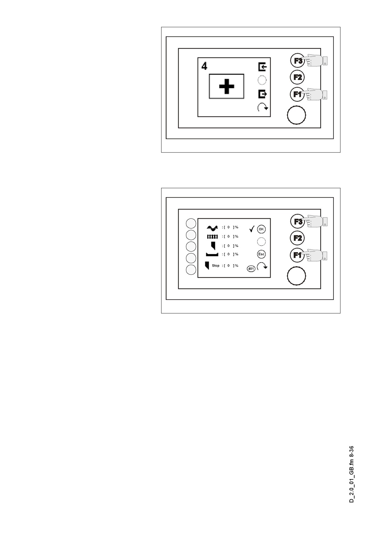
Menu 04 - Emergency func-
tion / stopping the screed
and turning on the tamper
In case of the loss of the
specified target value or of
the measuring of the actual
value
(e.g. faulty sensor,
transducer), the capacity of
the various functions can be
set for the automatic opera-
tion.
Terminal_SPS_Kette_635.wmf/Bild_004.bmp
- Open the submenu: (F3)
- Back to the main menu:
(F1)
Submenu 401 - Emergency
functions adjustment
Capacity change is possible
1
in case of the functions be-
low:
2
3
- Auger (1)
4
- Feeder conveyor (2)
5
- Tamper (3)
- Vibration (4)
- Tamper stop (5)
Terminal_SPS_Kette_635.wmf/Bild_401.bmp
A The current value can be set
between 0 and 100%.
A Adjustments of these functions can be carried out, only if a fault has occurred.
- Resetting of parameters, back to menu 04: (F1)
- Saving of set parameters, back to menu 04: (F3)
D 2.0 8
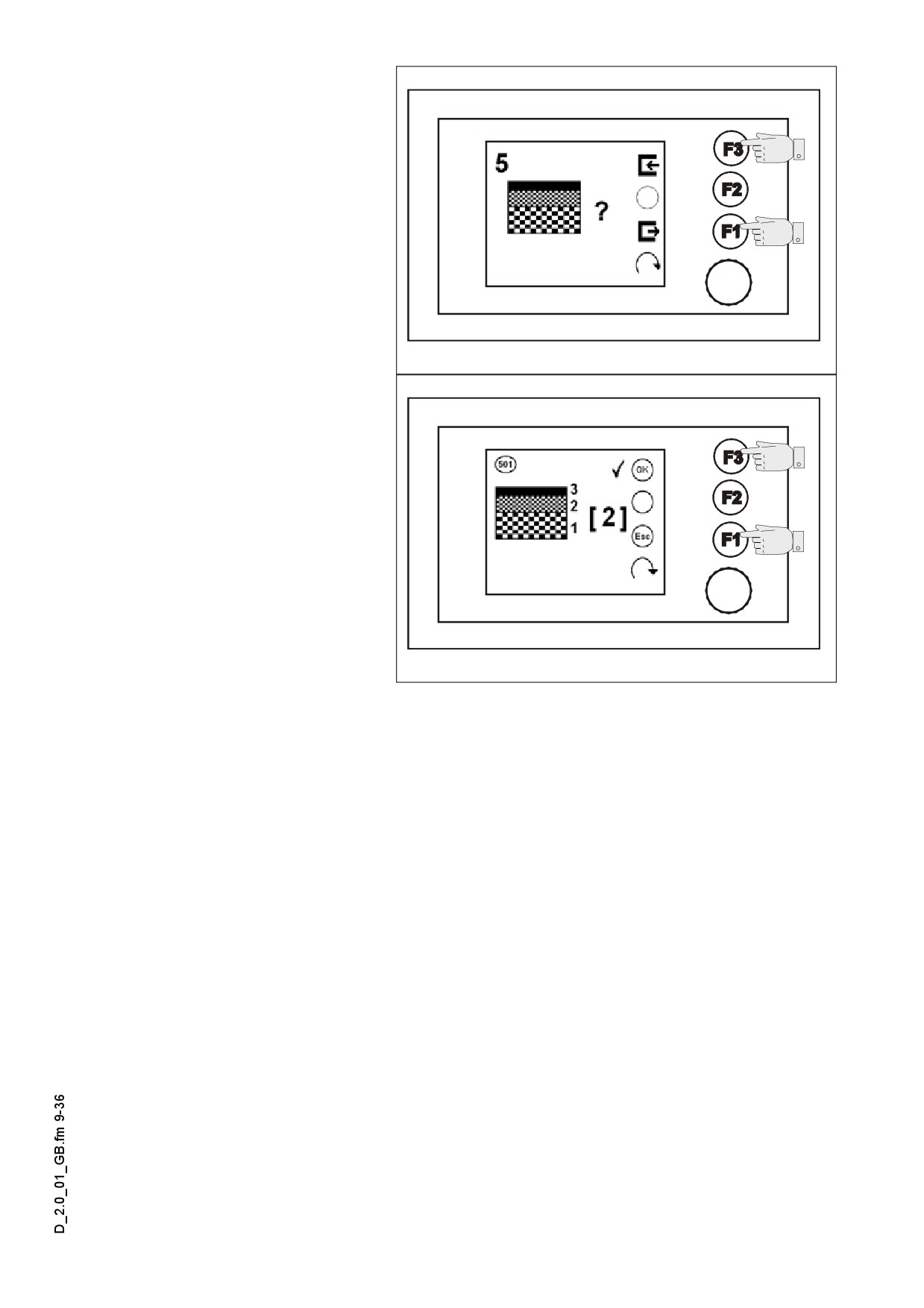
Menu 05 - Layer thickness
Menu for setting the type of
layer to be processed
- Open the submenu: (F3)
- Back to the main menu:
(F1)
Terminal_SPS_Kette_635.wmf/Bild_005.bmp
Submenu 501 - Preselec-
tion of layer thickness
The following types of layers
can be selected:
- Top layer: 3 parameters
- Binder course
2 parame-
ters
- Load bearing course: 1 pa-
rameter
- Saving, opening of
Terminal_SPS_Kette_635.wmf/Bild_501.bmp
submenu: (F3)
- Resetting changes,
back to submenu 05: (F1)
A Directly to the following submenu: (F3)
D 2.0 9
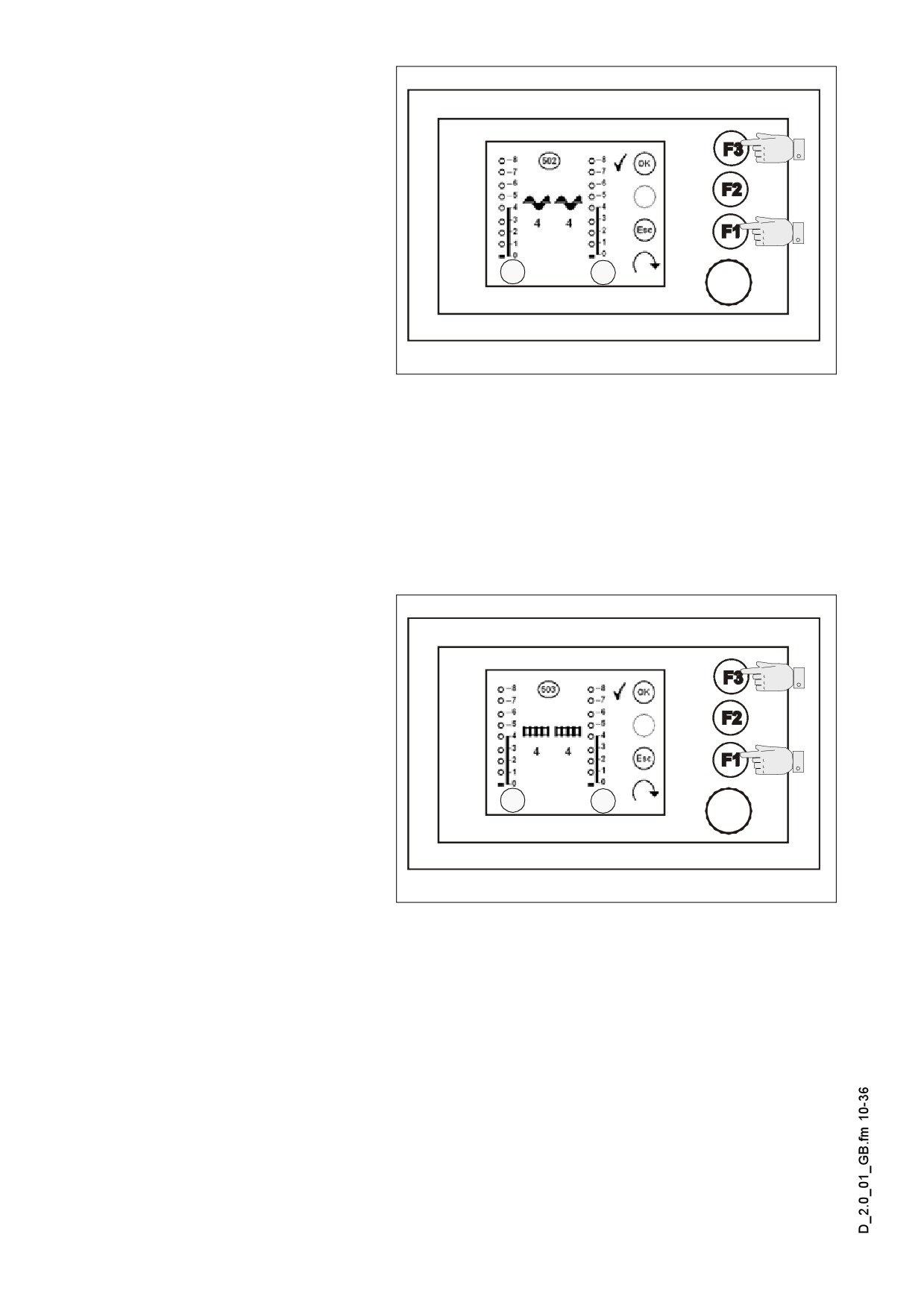
Submenu 502 - Setting the
speed of auger
The speed can be set in 8
stages. The actual speed se-
lected for the applicable feed-
er auger is shown on displays
(1) and (2).
Basic settings applicable to
1
2
the specific layer types:
- Top layer: 4
Terminal_SPS_Kette_635.wmf/Bild_502.bmp
- Binder course 6
- Load bearing course: 8
- Saving, opening of submenu: (F3)
- Resetting changes, back to submenu 05: (F1)
Directly to the following submenu: (F3)
A
The LED signals of the remote control units change according to the settings made.
A
Submenu 503 - Adjustment
of the speed of conveyor
The speed can be set in 8
stages. The actual speed se-
lected for the applicable con-
veyor is shown on display (1)
and (2).
Basic settings applicable to
1
2
the specific layer types:
- Top layer: 4
Terminal_SPS_Kette_635.wmf/Bild_503.bmp
- Binder course 6
- Load bearing course: 8
- Saving, back to submenu 05: (F3).
- Resetting changes, back to submenu 05: (F1).
The LED signals of the remote control units change according to the settings made.
A
D 2.0 10
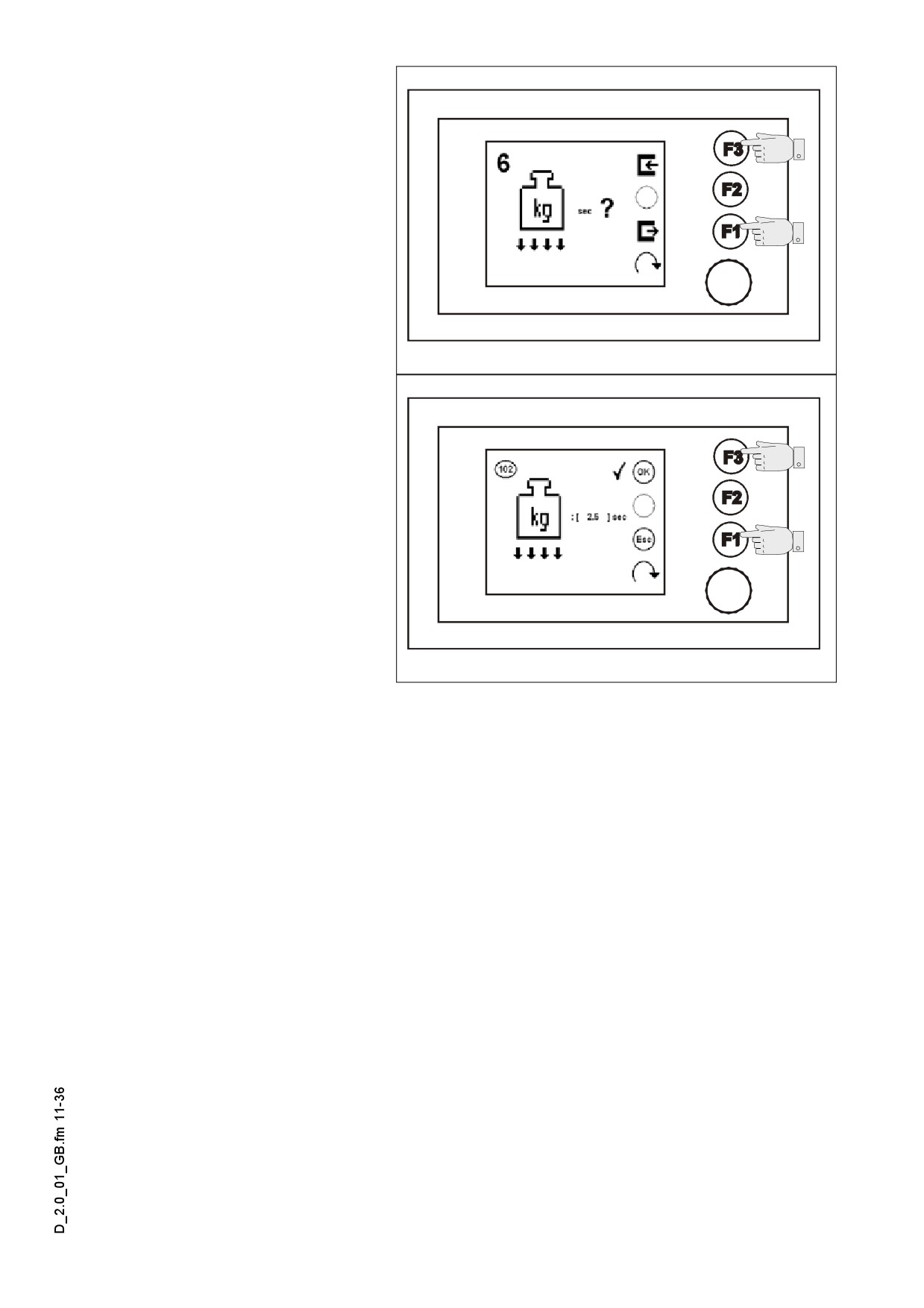
Menu 06 - Screed charging
Menu to set the starting load
- Open the submenu: (F3)
- Back to the main menu:
(F1)
Terminal_SPS_Kette_635.wmf/Bild_006.bmp
Submenu
102
- Starting
load setting
Setting the duration of start-
ing load
- Saving, back to submenu
06: (F3)
- Resetting changes, back to
menu 06: (F1)
Terminal_SPS_Kette_635.wmf/Bild_102.bmp
D 2.0 11
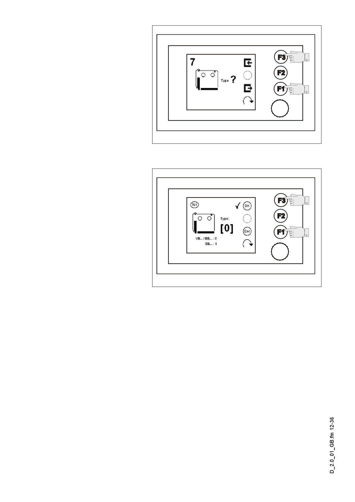
Menu 07 - Screed type
Menu for adjusting the screed
type
- Open the submenu: (F3)
- Back to the main menu:
(F1)
Terminal_SPS_Kette_635.wmf/Bild_007.bmp
Submenu 701 - Setting the
screed type
The following screed types
can be set:
- VB/EB-screed type: 0 pa-
rameter
- SB-screed: 1 parameter
- Saving, back to submenu
07: (F3)
- Resetting changes,
Terminal_SPS_Kette_635.wmf/Bild_701.bmp
back to menu 07: (F1)
D 2.0 12
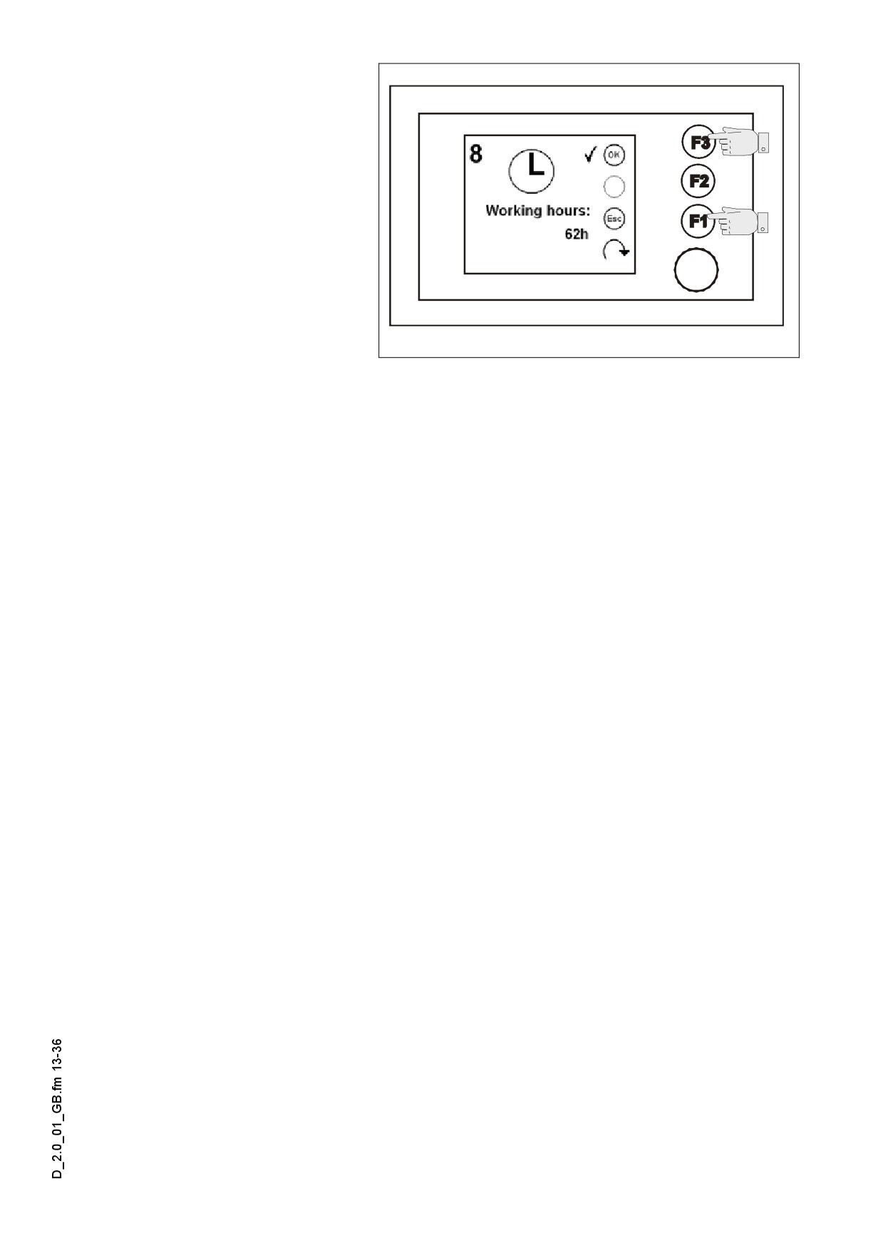
Menu 08 - Service hour me-
ter
Menu to query the service
hours
- Back to the main menu:
(F1) or (F3)
Terminal_SPS_Kette_635.wmf/Bild_008.bmp
D 2.0 13
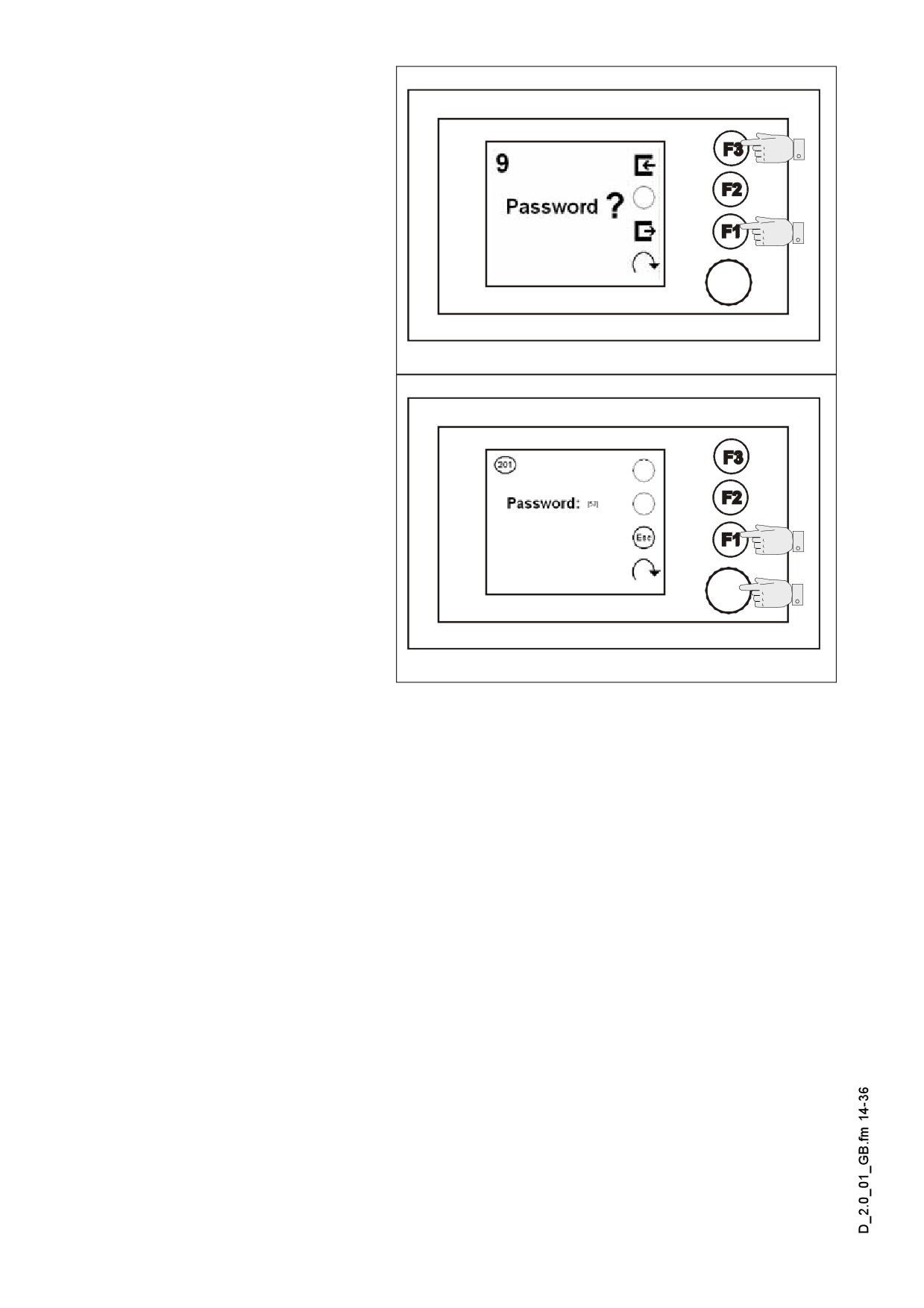
Menu 09 - Service
Password protected menu to
perform the various service
settings
- Password prompt opening:
(F3)
- Back to the main menu:
(F1)
Terminal_SPS_Kette_635.wmf/Bild_009.bmp
Submenu 201 - Password
prompt
Enter password:
- The password can be con-
firmed by pressing the En-
coder
- Back to menu 09: (F1)
Terminal_SPS_Kette_635.wmf/Bild_201.bmp
D 2.0 14
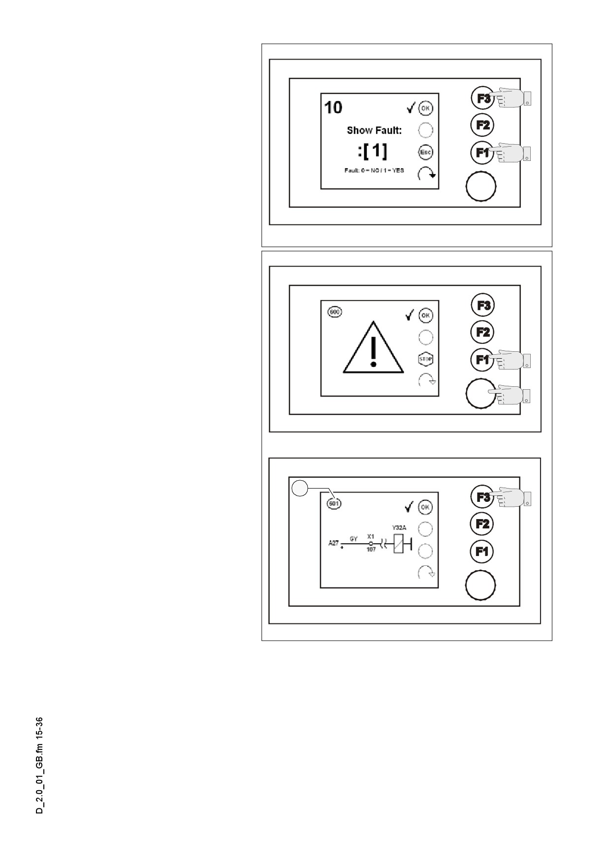
Menu 10 - Error memory
Menu for the repeated query
of error messages
- Display (0): There is no er-
ror message
- Display (1): Fault message
can be displayed
- Error message query: (F3)
- Back to the main menu:
(F1)
Terminal_SPS_Kette_635.wmf/Bild_010.bmp
Error message display:
In case of error messages
A
first always the message
(600) „Attention“ is displayed
- Error message display:
(F3)
- Back to menu 10: (F1)
Error display
- Calling down the next fault:
(F3)
1
A If additional faults have also
occurred, again the message
„Attention“ will be displayed.
A When the last error mes-
sage was read, the system
returns to the main menu.
A All the error messages can
be identified in the chapter
Terminal_SPS_Kette_635.wmf/Bild_600.bmp//Bild_601.bmp
„Error messages of Termi-
nal“.
A In case you use the help of Technical Support for your machine, always specify the
number of the error message (1).
D 2.0 15
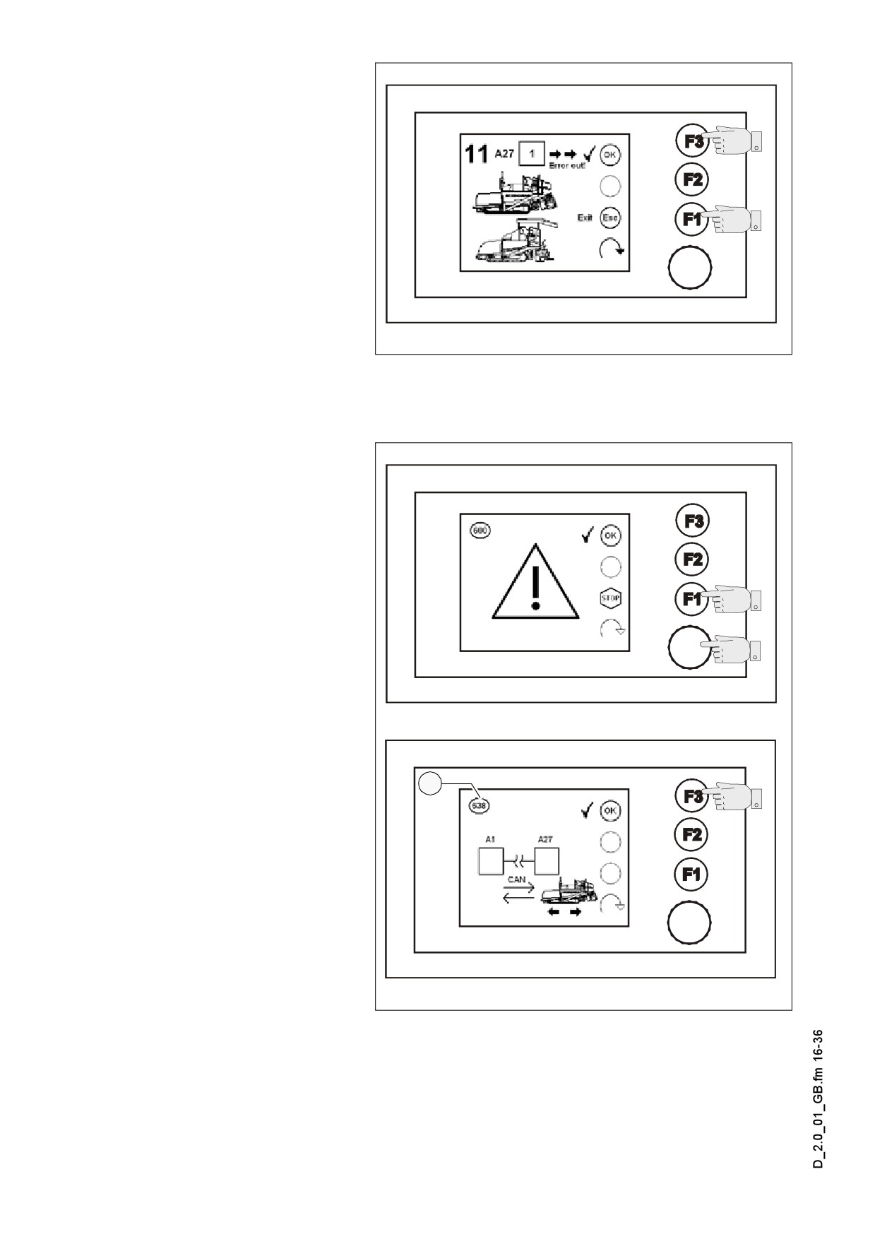
Menu 11 - Error memory
Computer of machine oper-
ation
Menu for the repeated query
of error messages sent by
the computer of machine op-
eration
- Display (0): There is no er-
ror message
- Display (1): Fault message
can be displayed
Terminal_SPS_Kette_635.wmf/Bild_011.bmp
- Retrieval of error message:
(F3)
- Back to the main menu: (F1)
Error message display:
A In case of error messages
first always the message
(600) „Attention“ is displayed
- Error message display:
(F3)
- Back to menu 10: (F1)
Error display
- Calling down the next fault:
(F3)
1
A If additional faults have also
occurred, again the message
„Attention“ will be displayed.
A When the last error mes-
sage was read, the system
returns to the main menu.
A All the error messages can
be identified in the chapter
Terminal_SPS_Kette_635.wmf/Bild_600.bmp/Bild_638.bmp
„Error messages of Termi-
nal“.
A In case you use the help of Technical Support for your machine, always specify the
number of the error message (1).
D 2.0 16
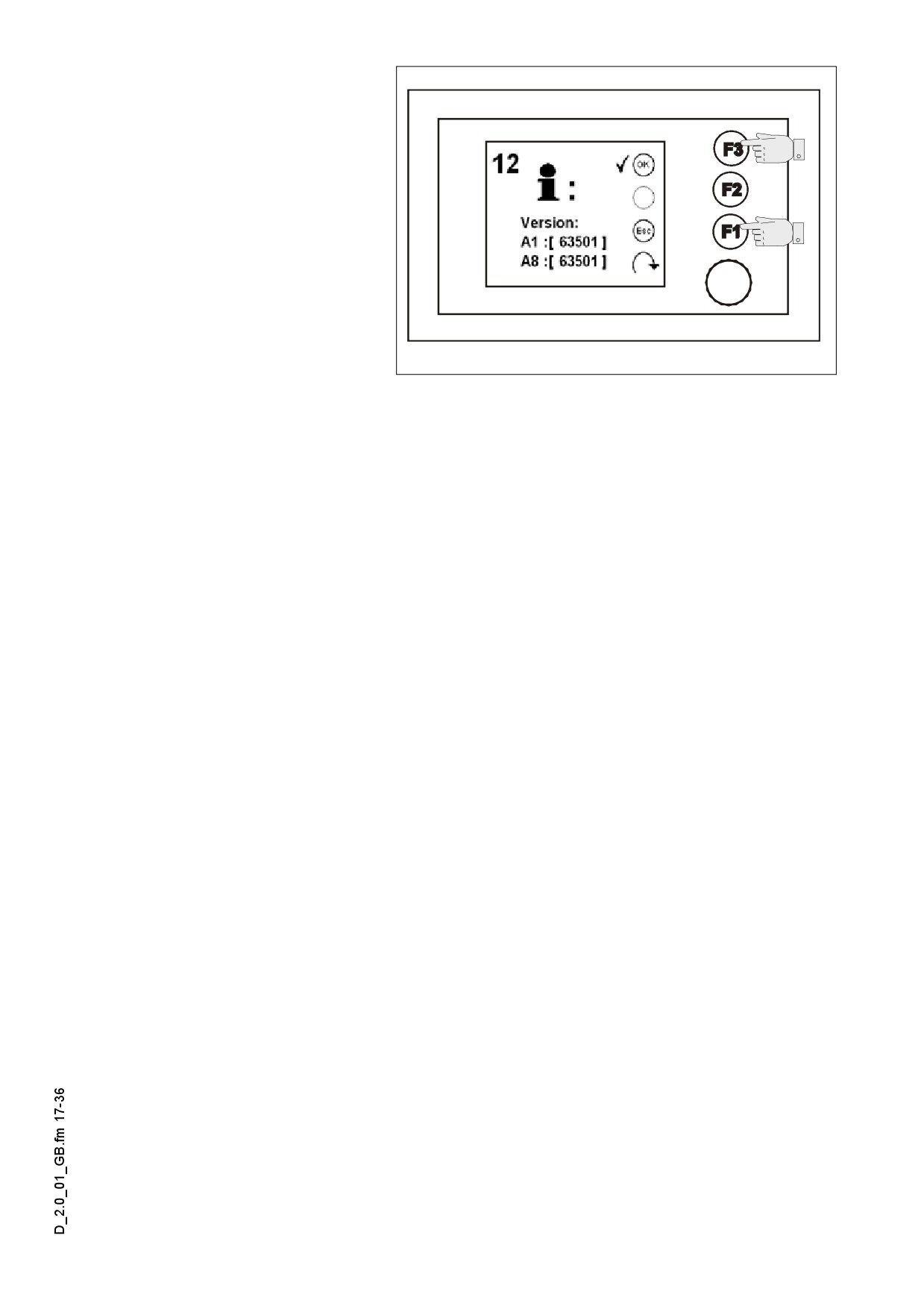
Menu 12 - Program version
Menu to query the version
number of the installed pro-
gram
A In case you use the help of
Technical Support for your
machine, always specify the
version number of the pro-
gram.
- Back to the main menu:
Terminal_SPS_Kette_635.wmf/Bild_012.bmp
(F1) or (F3)
D 2.0 17
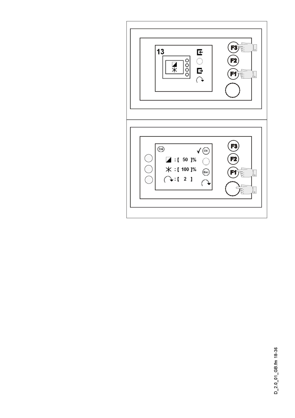
Menu 13 - Terminal settings
Menu for the various settings
of the terminal
- Open the submenu: (F3)
- Back to the main menu:
(F1)
Terminal_SPS_Kette_635.wmf/Bild_013.bmp
Submenu 104 - Terminal
settings
Setting of Contrast (1)
brilliance of display
(2) and
the sensitivity of Encoder (3)
1
- Saving, back to submenu
2
13: (F3)
3
- Resetting changes,
back to submenu 13: (F1)
Terminal_SPS_Kette_635.wmf/Bild_104.bmp
D 2.0 18
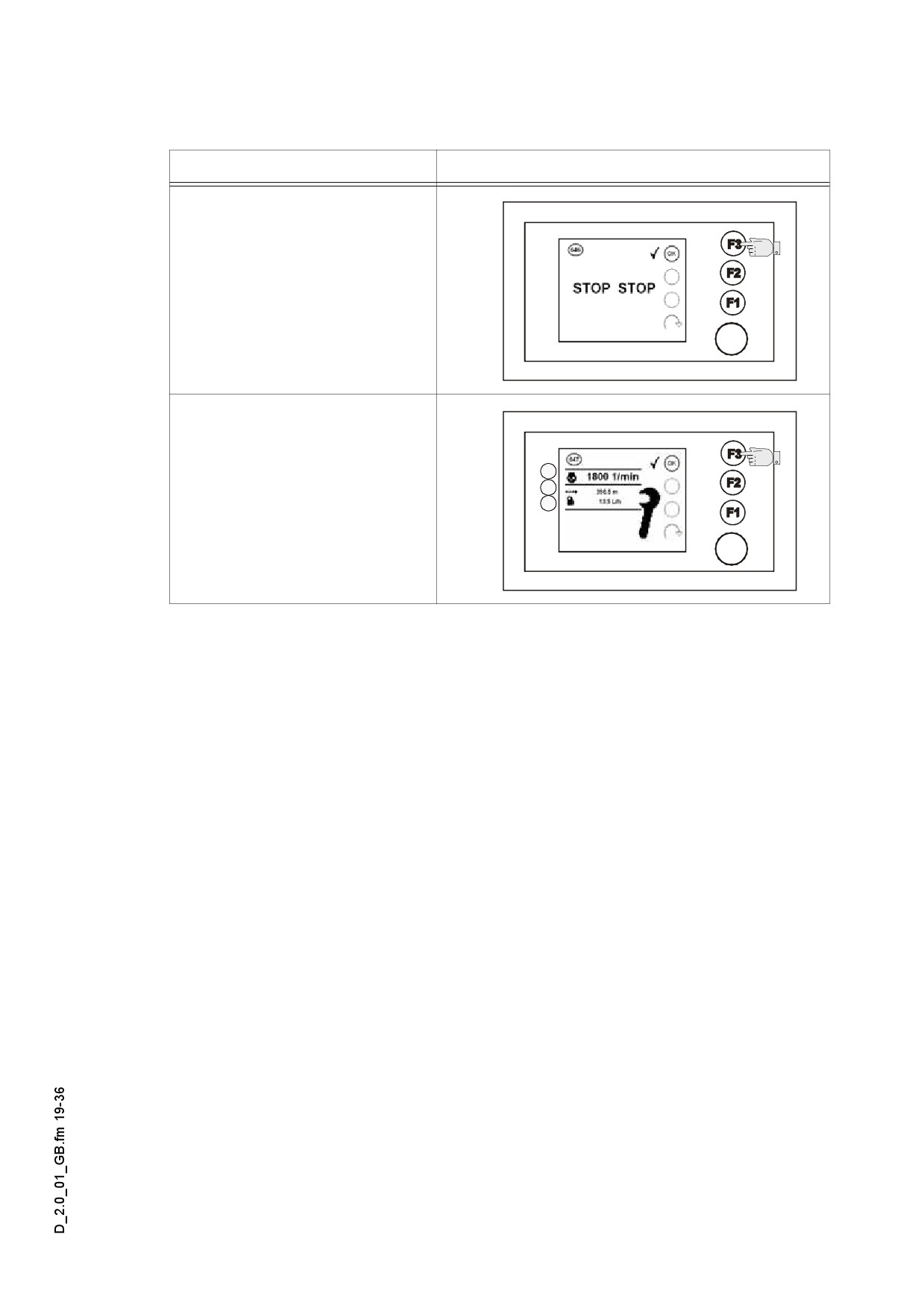
1.2
Further messages on the display
Display No. / report
Display
message 646
Emergency stop button de-
pressed
- Back to the previous menu:
(F3)
message 647
Adjustment mode
Displays:
1
- Engine speed (1)
2
- Trip covered (2)
3
- Fuel consumed
(calculated value) (3)
- Back to the previous menu:
(F3)
D 2.0 19
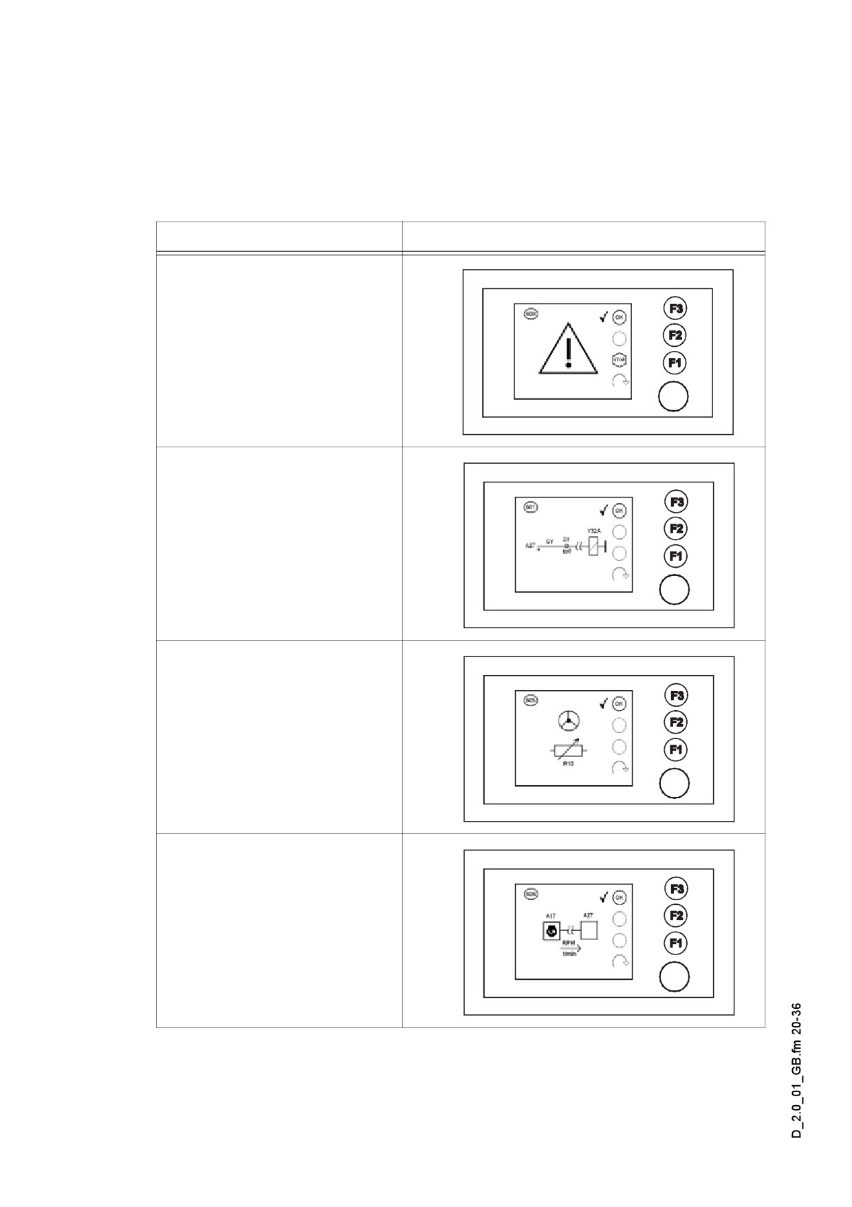
2
Terminal error messages
A Each error message is assigned a number. If you use the help of the Technical Sup-
port for your machine, please, provide this number and all information included in the
error message.
Fault No. / report
Display
600. error message
General fault display
601. error message
Broken wire
Pump of travel automatic /
drive lever
605. error message
- Faulty steering
potentiometer
606. error message
- Communication interrupted
Drive motor of travel
automatic unit
D 2.0 20
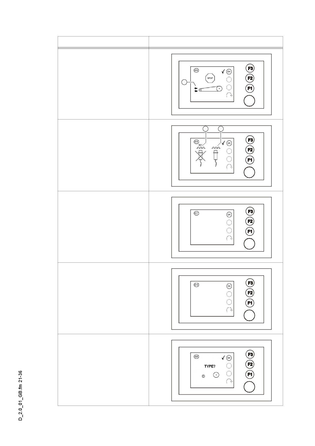
Fault No. / report
Display
610. error message
-
„Drive lever forward“ locked
1
Variable:
- Drive / steering direction (1)
1
2
615. error message
- Sensor of running gear
faulty
Variable:
- LH-side sensor (1)
- RH-side sensor (2)
617. error message
- Broken line - drive lever
pump control
619. error message
- Short circuit / line fault -
drive lever potentiometer /
drive lever - microswitch
(opposite switch)
620. error message
- The type of paver finisher is
not set in the service
software
D 2.0 21
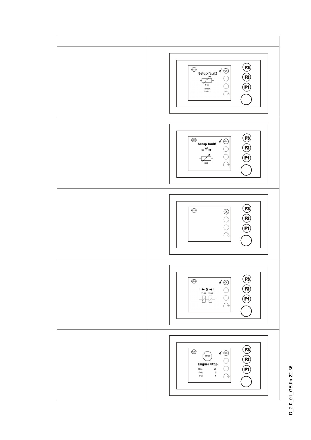
Fault No. / report
Display
621. error message
- Setup fault of travel speed
potentiometer in the service
software.
622. error message
- Drive lever potentiometer
setup-fault in the service
software.
623. error message
- Short circuit / line fault -
drive lever microswitch
forward / reverse (parallel
switch)
624. error message
- Pump current zero position
(dead band) not specified in
the service software.
625. error message
Fault with the engine position
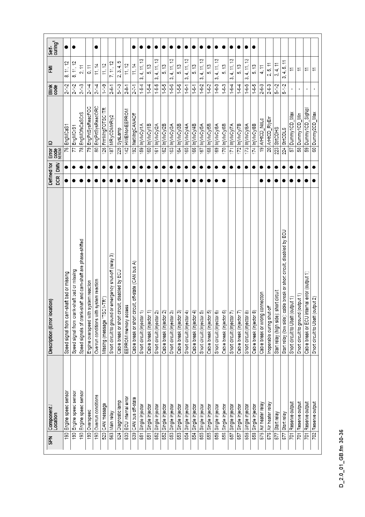
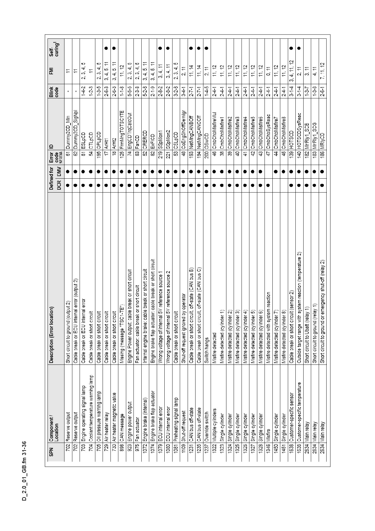
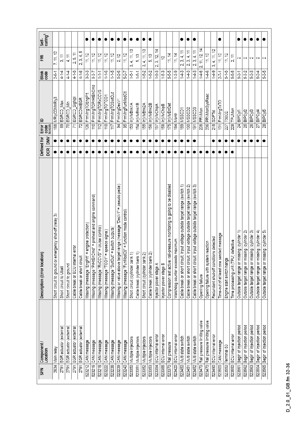
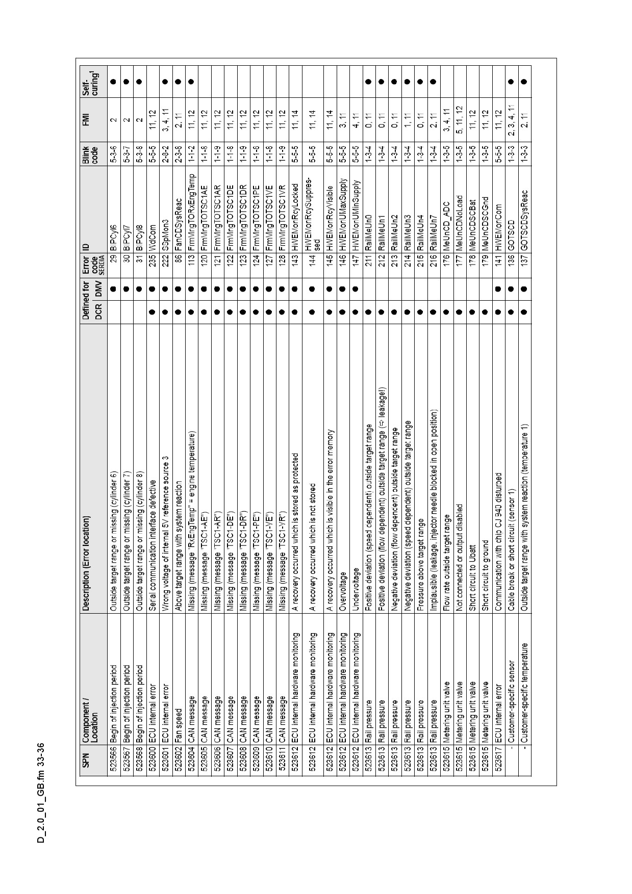
SPN = part concerned
FMI = type of fault
OC = frequency of repetition
A see chapter „Fault
codes of drive engine“.
D 2.0 22
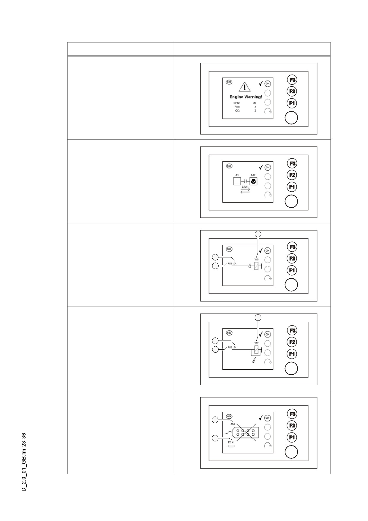
Fault No. / report
Display
626. error message
- Warning signal of traction
engine
- SPN = part concerned
- FMI = type of fault
- OC = frequency of repetition
A see chapter „Fault
codes of traction en-
gine“.
628. error message
- Communication interrupted
Master drive engine
3
629. error message
- Slave output wire broken
2
Variable:
1
- Slave No. (1)
- Slave-output (2)
- Controlled element (3)
3
630. error message
- Slave output short circuit
2
Variable:
1
- Slave No. (1)
- Slave-output (2)
- Controlled element (3)
634. error message
1
- Slave fault
Variable:
2
- Slave No. (1)
- Fuse (2)
D 2.0 23
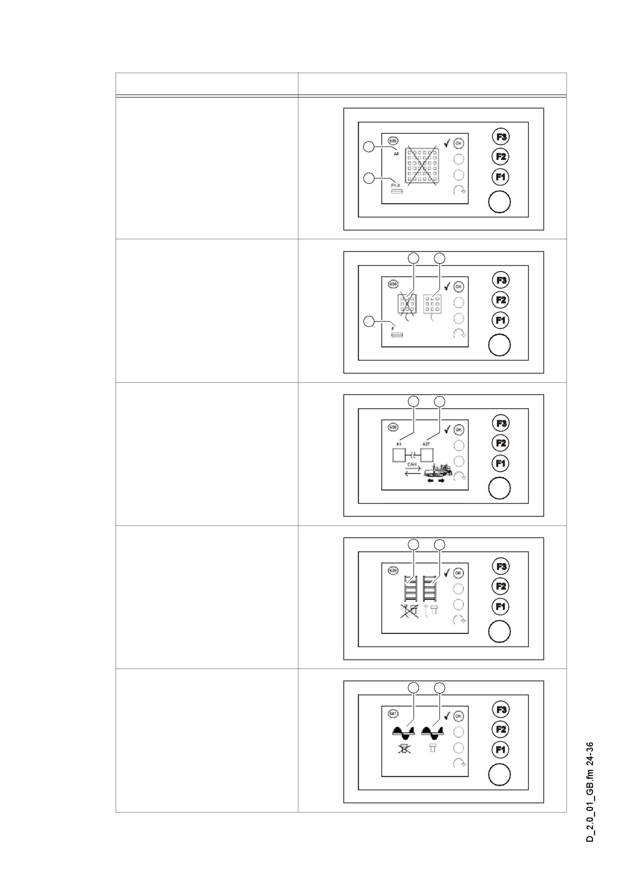
Fault No. / report
Display
1
635. error message
- Keyboard fault /
2
Keyboard fuse faulty
1
2
636. error message
- Remote control fault /
Keyboard fuse faulty
Variable:
3
- LH-side remote control (1)
- RH-side remote control (2)
- Remote control fuse (3)
638. error message
1
2
- Communication interrupted
Master drive automatic
system
A Observe the rules de-
scribed in Chapter „In-
structions
for
fault
messages“.
1
2
639. error message
- Conveyor limit switch faulty
Variable:
- LH-side limit switch (1)
- RH-side limit switch (2)
1
2
641. error message
- Auger limit switch faulty
Variable:
- LH-side limit switch (1)
- RH-side limit switch (2)
D 2.0 24
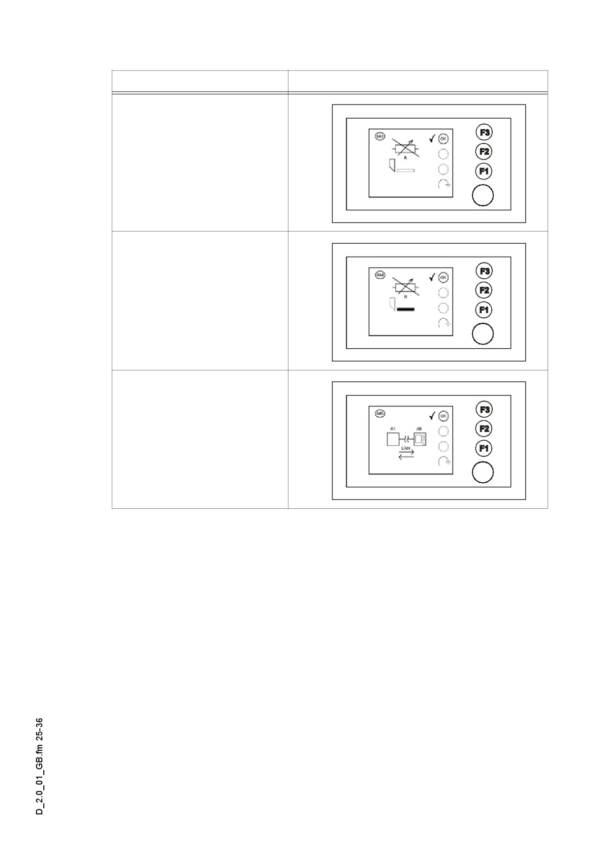
Fault No. / report
Display
643. error message
- Tamper target value
potentiometer faulty
644. error message
- Vibrator target value
potentiometer faulty
645. error message
- Communication interrupted
Master display
D 2.0 25
2.1
Instructions related to error messages
638. error message
Communication interrupted
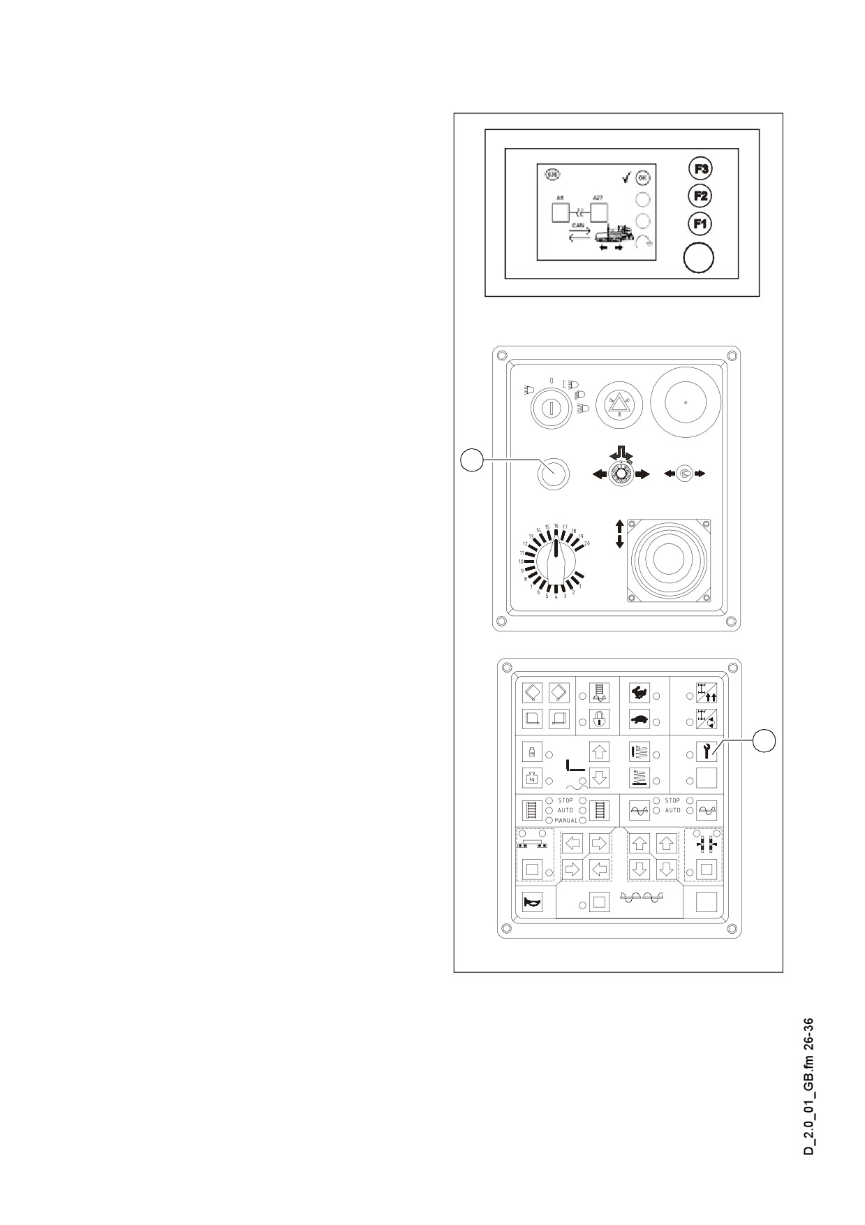
Master drive automatic system.
A First check if the fuse F5.1 is good.
If the cause of the interrupted data link is
not the fuse, the Diesel engine can be
started.
- Switch on button (1) (LED comes on)
- Press start button (2).
2
1
Terminal_SPS_Kette_635.wmf/Element1_SPS_Kette_635.wmf/,
Element2_SPS_Kette_635.wmf
D 2.0 26
2.2
Fault codes of the traction engine.
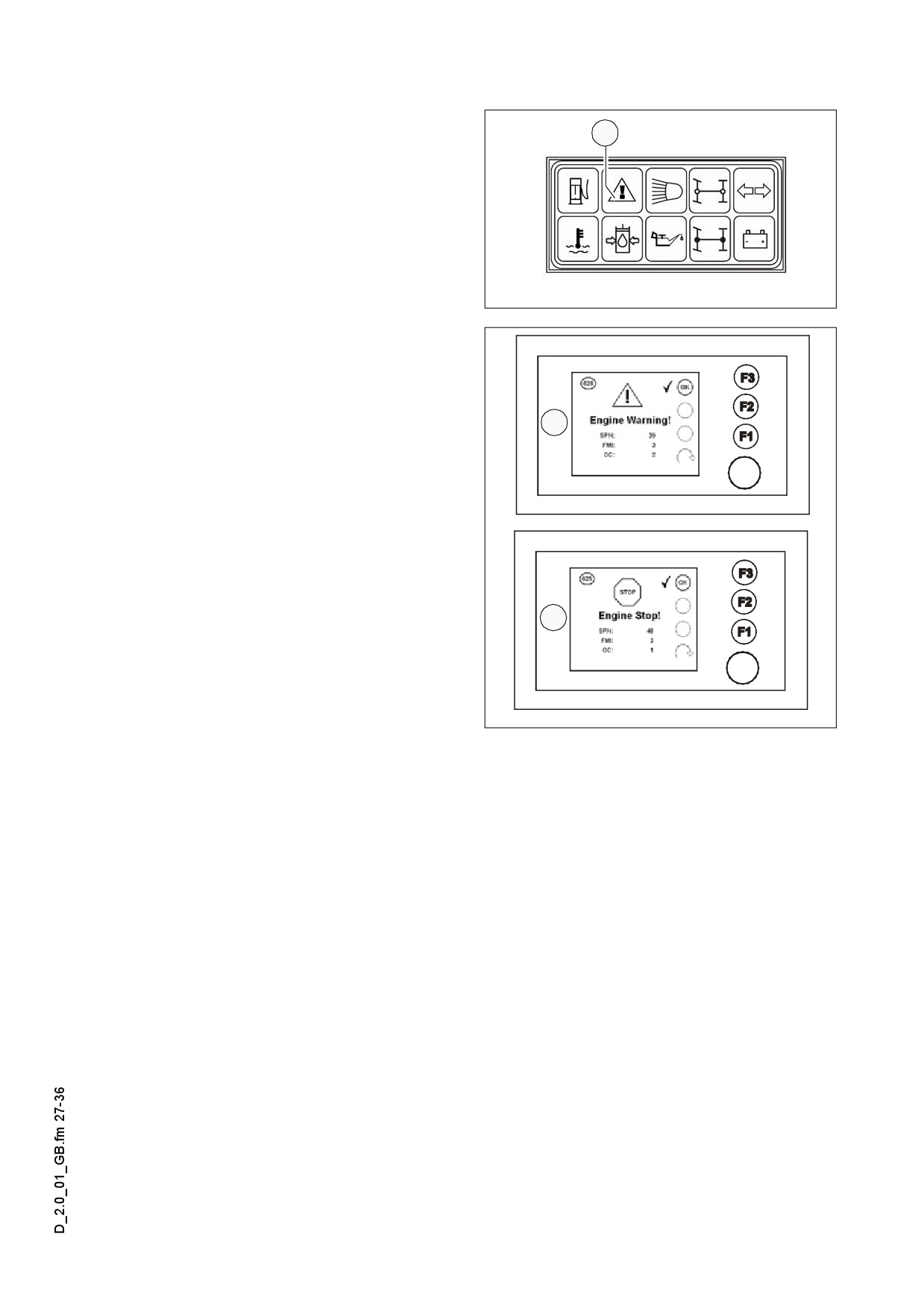
If a fault occurs in the traction engine,
1
this is indicated by the specific signal
lamp (1) and simultaneously an explana-
tion appears on the display.
Leuchtmodul_SPS_Kette_635.bmp
The error message displayed simultane-
ously includes several error codes, the
decoding of which clearly defines the
fault.
2
- The display „ENGINE WARNING“ (2)
indicates that a fault has occurred in
the traction engine. The machine can
be further operated temporarily. In or-
der to prevent further damage, the er-
ror should however be rectified as
soon as possible.
-
„STOP ENGINE!“ (Stop Engine!) dis-
play (3) the traction engine is failed to
3
such an extent that the engine imme-
diately stops automatically, or it has to
be stopped to avoid further damage.
D 2.0 27
Example:
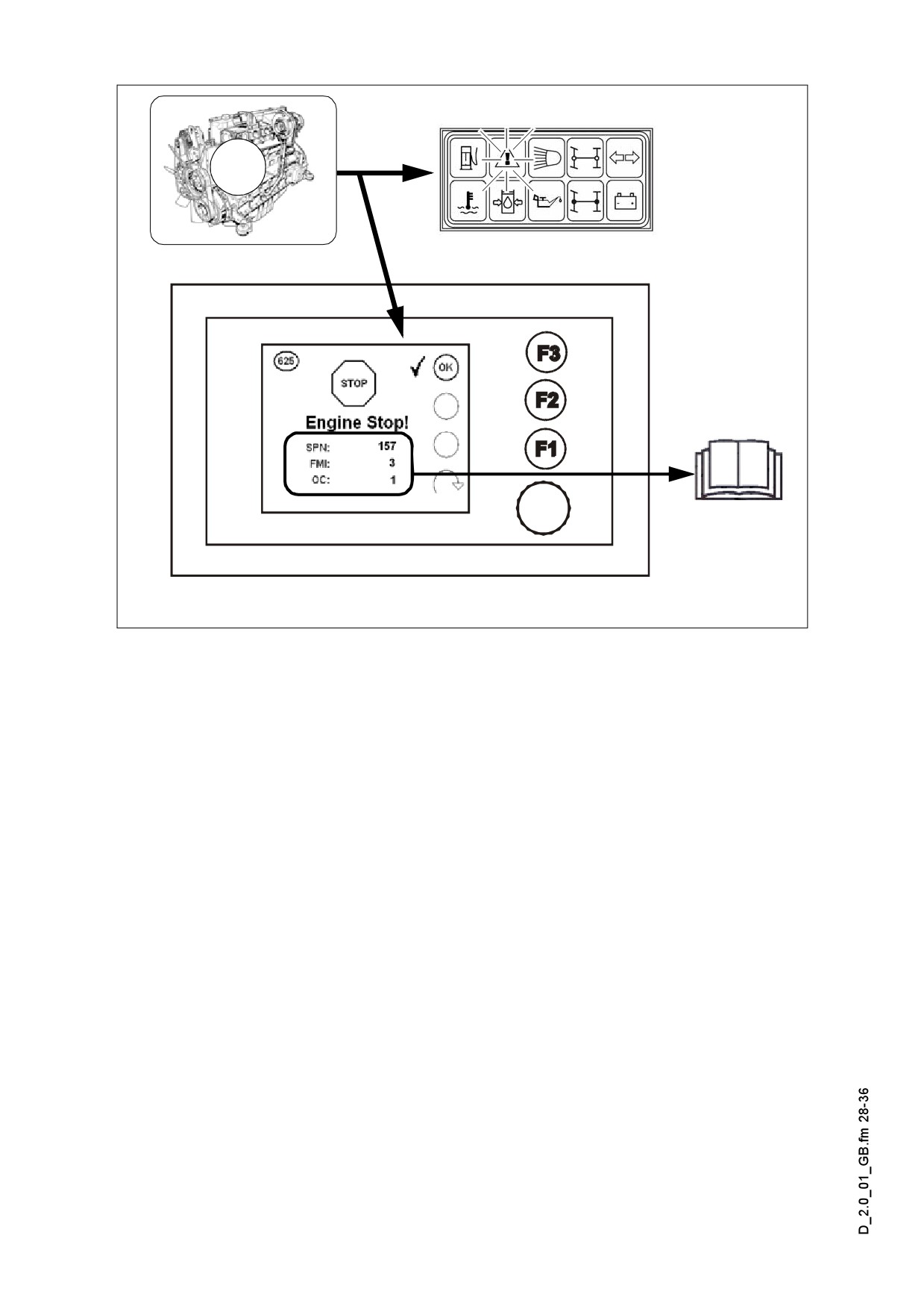
?
Explanation:
The flashing control lamp marks the serious failure of the traction engine and the en-
gine will stop automatically or it has to be stopped.
Display:
SPN:
157
FMI:
3
OC:
1
Cause: Cable failure in the Rail pressure detector.
Effect: The engine switches off.
Frequency: The fault occures for the first time.
m Report the displayed fault code to the customer service of the paver finisher and they
will discuss with you the steps to be taken.
D 2.0 28
2.3
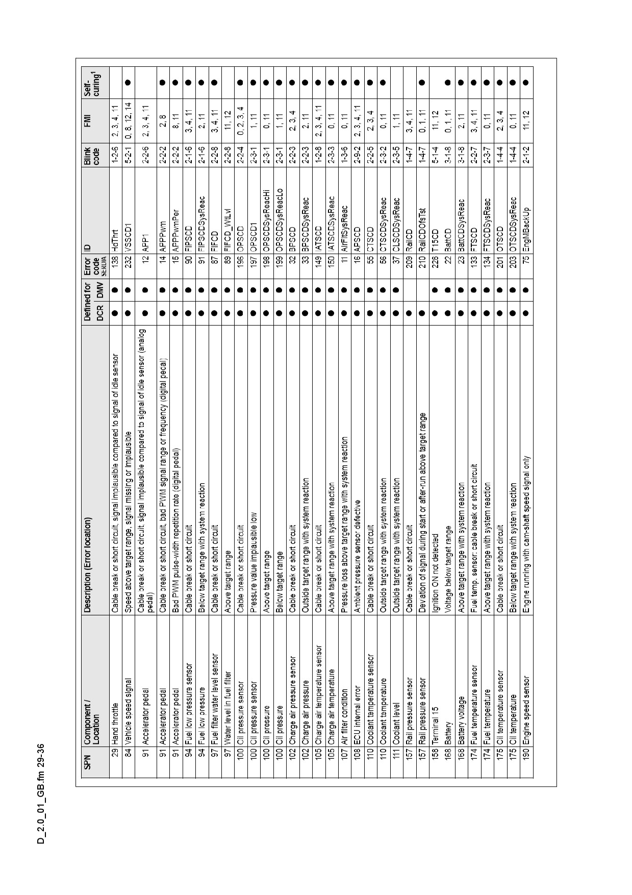
Error messages
D 2.0 29
D 2.0 30
D 2.0 31
D 2.0 32
D 2.0 33
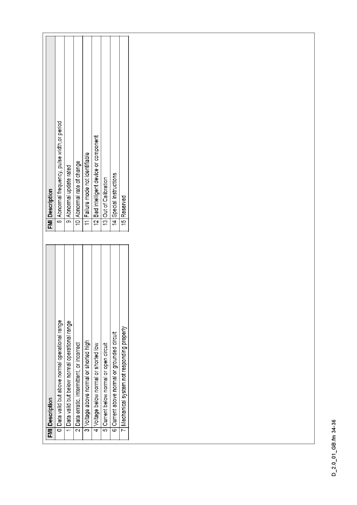
2.4
FMI-codes
D 2.0 34