DYNAPAC Paver finisher F 121 C, F 141 C Type 635. Operation & Maintenance (Order number: 4812026925) - page 5
2
Malfunctions
2.1
Problems during paving
Problem
Cause:
-
change in the material temperature, demixing
-
wrong material composition
-
incorrect operation of the roller
-
incorrectly prepared foundation
-
long standstill times between loads
-
grade control reference line is not suitable
-
grade control jumps to the reference line
-
grade control toggles between up and down
Wavy surface
(inertia setting is too high)
(”short waves”)
-
bottom plates of the screed are loose
-
bottom plates of the screed are warped or not uniformly
worn
-
screed does not work in the floating position
-
too much play in the mechanical screed link/suspension
-
paver finisher speed is too high
-
augers are overloaded
-
changing material pressure against the screed
-
change in the material temperature
-
demixing
-
roller has stopped on the hot material
-
roller has turned or roller speed has been changed too fast
-
incorrect operation of the roller
-
incorrectly prepared foundation
-
truck brake is applied too tight
-
long standstill times between loads
Wavy surface
-
grade control reference line is not suitable
(”long waves”)
-
incorrect installation of the grade control
-
limit switch is not correctly set
-
screed is empty
-
screed has not been switched to the floating position
-
too much play in the mechanical screed link
-
auger is set too deep
-
auger is overloaded
-
changing material pressure against the screed
-
material temperature is too low
-
change in the material temperature
-
moisture on the foundation
Cracks in the layer
-
demixing
(over the entire
-
wrong material composition
width)
-
wrong layer height for the maximum grain size
-
cold screed
-
bottom plates of the screed are worn or warped
-
paver finisher speed is too high
-
temperature of the material
Cracks in the layer
-
cold screed
(center strip)
-
bottom plates are worn or warped
-
wrong crowning
D4.1 23
Problem
Cause:
-
temperature of the material
-
screed extendable parts are incorrectly installed
Cracks in the layer
-
limit switch is not correctly set
(outer strip)
-
cold screed
-
bottom plates are worn or warped
-
paver finisher speed is too high
-
temperature of the material
-
change in the material temperature
-
moisture on the foundation
-
demixing
-
wrong material composition
-
incorrectly prepared foundation
-
wrong layer height for the maximum grain size
Layer composition is
-
long standstill times between loads
not uniform
-
vibration is too slow
-
screed extendable parts are incorrectly installed
-
cold screed
-
bottom plates are worn or warped
-
screed does not work in the floating position
-
paver finisher speed is too high
-
auger is overloaded
-
changing material pressure against the screed
-
truck hits too much against the paver finisher while aligning
to the paver finisher
Marks in the surface
-
too much play in the mechanical screed link/suspension
-
truck brake is applied
-
vibration is too high while standing on a spot
-
temperature of the material
-
change in the material temperature
Screed does not re-
-
wrong layer height for maximum grain size
act to corrective
-
incorrect installation of the grade control
measures as expect-
-
vibration is too slow
ed
-
screed does not work in the floating position
-
too much play in the mechanical screed link
-
paver finisher speed is too high
D4.1 24

2.2
Malfunctions on the paver finisher or screed
Malfunction
Cause:
Remedy
See operating instructions for
At the diesel engine
Diverse
the engine
See ”External starting”
Diesel engine does
Batteries empty
(start assistance)
not start
Diverse
see ”Towing”
Tamper is obstructed by
Properly heat the screed
cold bitumen
Hydraulic oil level in the
Top up the oil
tank is too low
Pressure limiting valve is
Replace the valve; if necessary,
Tamper or vibration
defective
repair and adjust the valve
does not operate
Seal or replace the connections
Leak in the suction line of
Tighten or replace the hose
the pump
clamps
Clean the filter; if necessary,
Oil filter is soiled
replace the filter
Hydraulic oil level in the
Top up the oil
tank is too low.
Check fuses and cables; replace
Power supply is interrupted
if necessary
Switch is defective
Replace the switch
One of the pressure limiting
Repair or exchange the valves
Conveyor or augers
valves is defective
run too slowly
Pump shaft broken
Replace the pump
Limit switch does not switch
Check the switch; replace and
or regulate correctly
adjust the switch if necessary
Check the high pressure filter for
Pump is defective
dirt particles; replace if
necessary
Oil filter is soiled
Replace the filter
Engine speed is too low
Increase the speed
Hydraulic oil level is too low
Top up the oil
Leak in the suction line
Tighten the connections
Flow rate regulator
Replace
Hopper cannot be
defective
swung open
Leaking seals of the
Replace
hydraulic cylinder
Control valve is defective
Replace
Check fuse and cables; replace
Power supply interrupted
if necessary
D4.1 25

Malfunction
Cause:
Remedy
Control valve is defective
Replace
Hoppers lowers
Leaking seals of the
inadvertently
Replace
hydraulic cylinder
Oil pressure too low
Increase the oil pressure
Leaking seal
Replace
Screed cannot be
Screed relieving or
Switch must be in the center
lifted
charging is switched on
position
Check fuse and cables; replace
Power supply is interrupted
if necessary
Switch on the remote
Set the switch to ”manual”
control is set to ”auto”
Check fuse and cables; replace
Power supply is interrupted
if necessary
Switch on the operating
Crossbeams cannot
Replace
panel defective
be lifted or lowered
Excess pressure valve
Replace
defective
Flow rate regulator
Replace
defective
Seals defective
Replace
Control valves defective
Replace
Crossbeams lower
Pilot-controlled non-return
Replace
inadvertently
valves defective
Seals defective
Replace
D4.1 26

Malfunction
Cause:
Remedy
Replace
Traction drive fuse
(Fuse holder on the operating
defective
panel)
Check potentiometer, cables,
Power supply is interrupted
connectors; replace if necessary
Traction drive monitoring
Replace
(type-specific) defective
Traction does not
Electro-hydraulic servo unit
work
Replace the servo unit
of the pump defective
Check and adjust if necessary
Check the suction filter; replace
Insufficient supply pressure
the supply pump and the filter if
necessary
Drive shaft of hydraulic
Replace pump or engine
pumps or engines broken
Check the fuel level; refill fuel if
Fuel level too low
necessary
Irregular engine
Replace
Fuse ”engine speed
speed, engine stop
(fuse strip on the operating
control” defective
function does not
panel)
work
Defective power supply
Check potentiometer, cables,
cables (cables broken or
connectors; replace if necessary
short-circuited)
D4.1 27
3
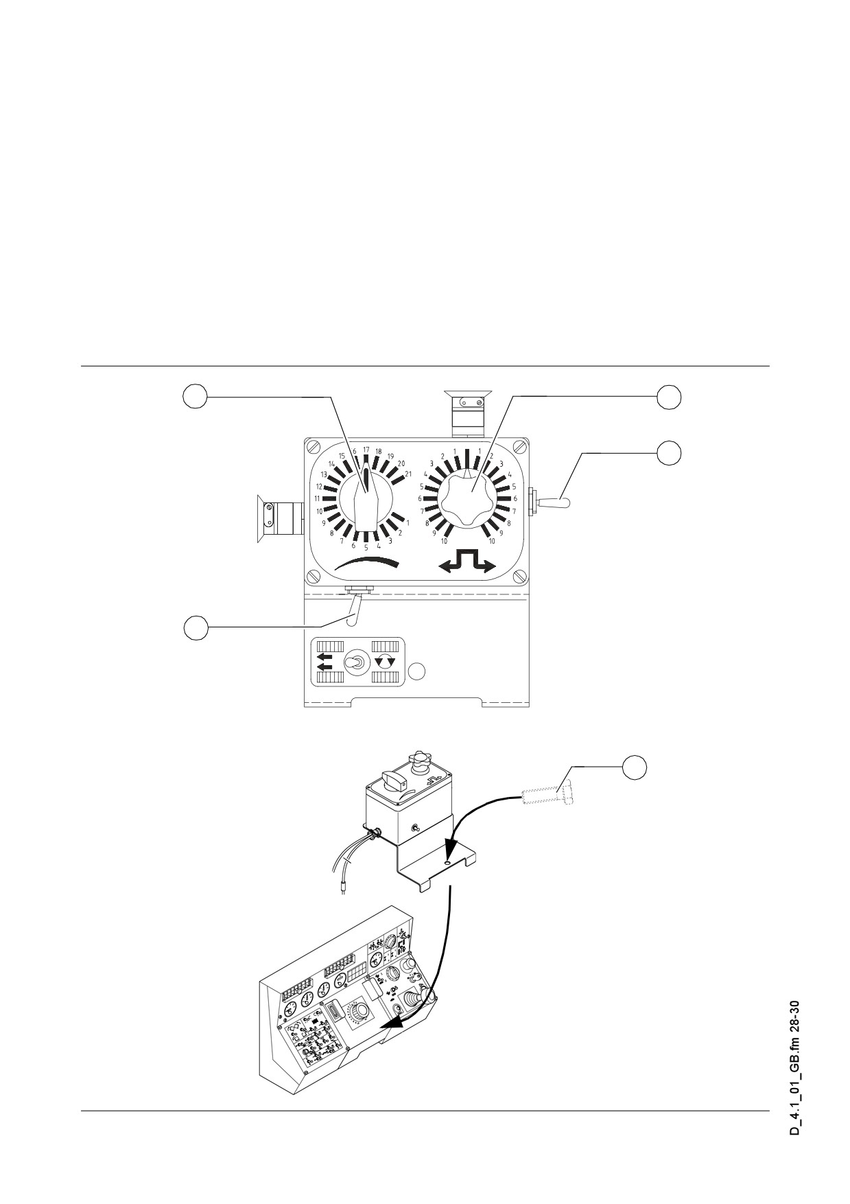
Emergency device/steering, drive system
In case of a malfunction in the electronic drive system it is possible to override the
system by an emergency device. This emergency device is included in the tool set of
every crawler machine.
To install the emergency device all plugs of the drive pump servo valves have to be
replaced by the plugs of the emergency device. (short screw driver is necessary.)
The cable shoe is connected to power supply of 24 Volts and the cable eye is con-
nected to ground.
The plug of the hydraulic brake valve is replaced by the corresponding plug of the
emergency device.
Voltage supply can be provided through a 24V connection plug.
The control unit is fastened on the operating panel.
To connect the plugs follow to the wiring diagram on the following page.
3
4
2
5
1
D4.1 28
Following functions are located in the steering unit:
No.
Denomination
1
Mounting screws for holder plate
2
Switch for preselection of the zero position and forward reverse movement
3
Adjustment knob for speed control (Replace speed preselector)
4
Steering knob
5
Switch to turn the paver finisher on the spot
Function
If the emergency device is connected all functions like engine speed, conveyor, au-
ger, tamper and vibration have to be controlled by the forward reverse lever.
Starting up for laying
- Preselect the speed with turning knob (3)
- Push switch (2) in forward direction
- Engage forward reverse lever like under normal conditions
- All other functions (4, 5) have to be in the position described in the instruction man-
ual (Operation)
Transport
- Adjust turning knob (3) to a low speed
- Push switch (2) to the recommended direction and engage the forward reverse le-
ver to forward direction.
- If the recommended direction is reverse push switch in reverse, but still the forward
reverse lever should be moved to forward direction
- Adjust the driving speed with turning knob (3)
- All other functions have to be in the position described in the instruction manual
(Operation)
When starting the engine, switch (2) must be in the zero position since the machine
f
would otherwise move off straightaway! Risk of accident!
D4.1 29
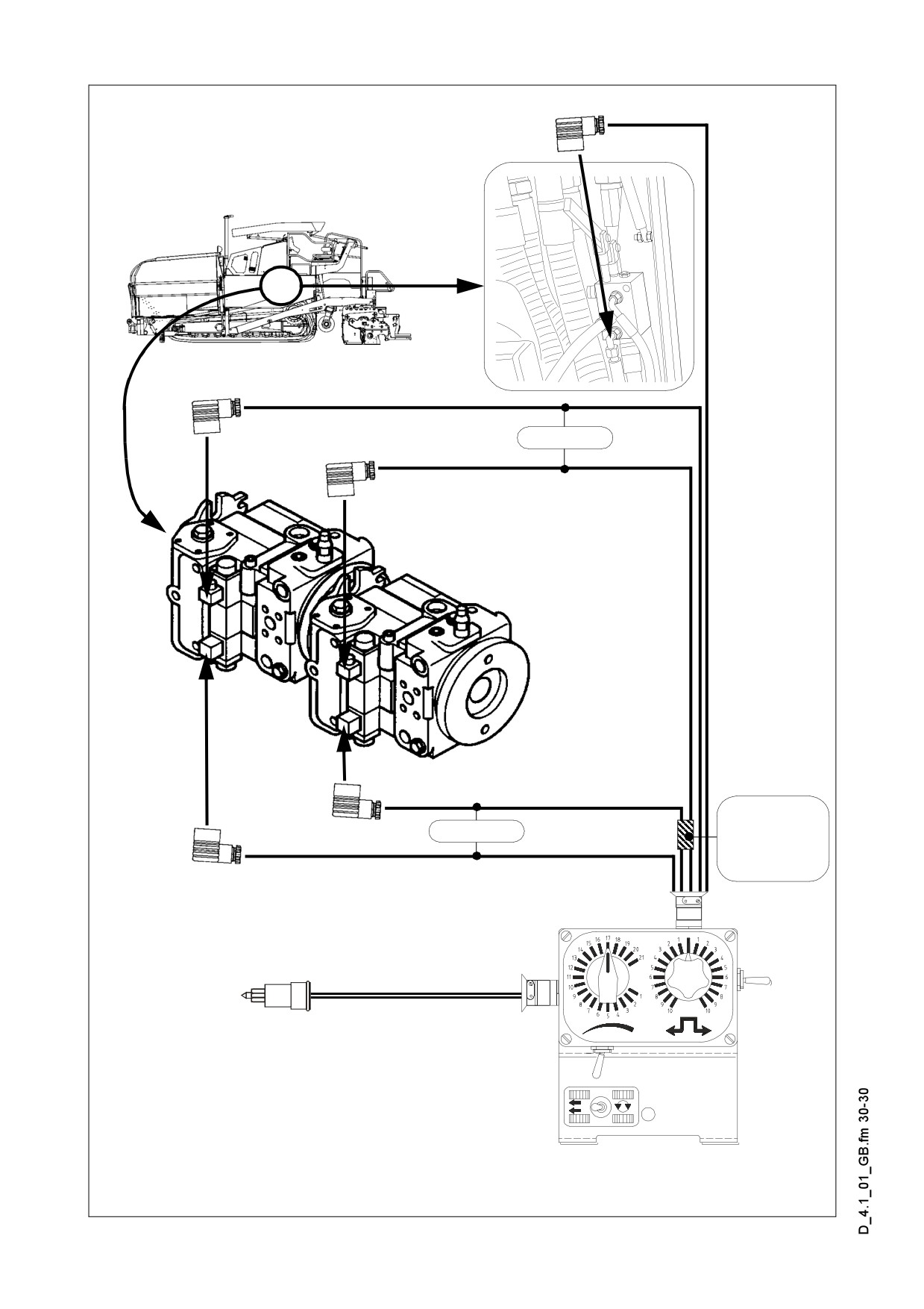
Gray
Wiring harness
for drive pump
Black
of left caterpillar
drive
Marked YELLOW!
24 V / Ground
Steering unit
D4.1 30
E 01
Set-up and modification
1
Special notes on safety
Danger to personnel by inadvertent starting of the engine, the traction drive, the con-
f
veyor, the auger, the screed or the lifting units. Unless specified otherwise, work may
only be performed when the engine is at a standstill!
- To protect the paver finisher against inadvertent starting:
Set the drive lever to the center position and set the preselector to zero; if applica-
ble, remove the drive traction fuse from the operating panel; pull out the ignition key
and the battery main switch.
- Secure lifted machine parts (e.g. screed or hopper) against lowering by means of
mechanical supports.
- Replace parts or have them replaced as stipulated.
When connecting or disconnecting hydraulic hoses and when working on the hydrau-
f
lic system, hot hydraulic fluid can spurt out at a high pressure.
Switch off the engine and de-pressurize the hydraulic system! Protect your eyes!
- Mount all protective devices before re-commissioning the paver finisher.
- The walking platform must always reach over the entire width of the screed. The
hinged walkway (option for all variable screeds) may only be swung up under the
following circumstances:
- When paving next to a wall or a similar obstacle.
- During transportation on a low-bed trailer.
E 01 1
2
Auger
2.1
Height adjustment
1
Depending on the mix of materials,
when working with layer thicknesses of
up to 15 cm, the height of the distribution
auger (1) - measured from its bottom
edge
- should be around
5 cm
(2 inches) above the material layer thick-
ness (depending on its mix of materials).
Example: Layer height 10 cm
Adjustment: 15 cm from the
F0130_A1.TIF
ground
An incorrect height adjustment can result in the following problems:
- Auger too high:
Too much material in front of the screed; material overflow. When operating with
larger widths, demixing and traction problems may occur.
- Auger too low:
Not enough material that can be precompacted by the auger. Irregularities resulting
from this cannot be completely compensated for by the screed (wavy surface).
In addition, an increased wear on the auger segments occurs.
2.2
Auger crossbeam installed in a fixed
position
- Lower the screed onto a suitable sup-
port (e.g. squared timbers).
- Completely extend both levelling cylin-
ders.
2
- Hook lifting chains (2) for lifting the au-
ger crossbeam into the hooks of the
F0131_A1.TIF
crossbeams.
- Loosen the fixing screws (3) of the auger crossbeam.
- Retract the levelling cylinders until the
auger crossbeam has reached the de-
sired height.
- Tighten the fixing screws (3) of the au-
ger crossbeam.
3
F129_A1.TIF
E 01 2
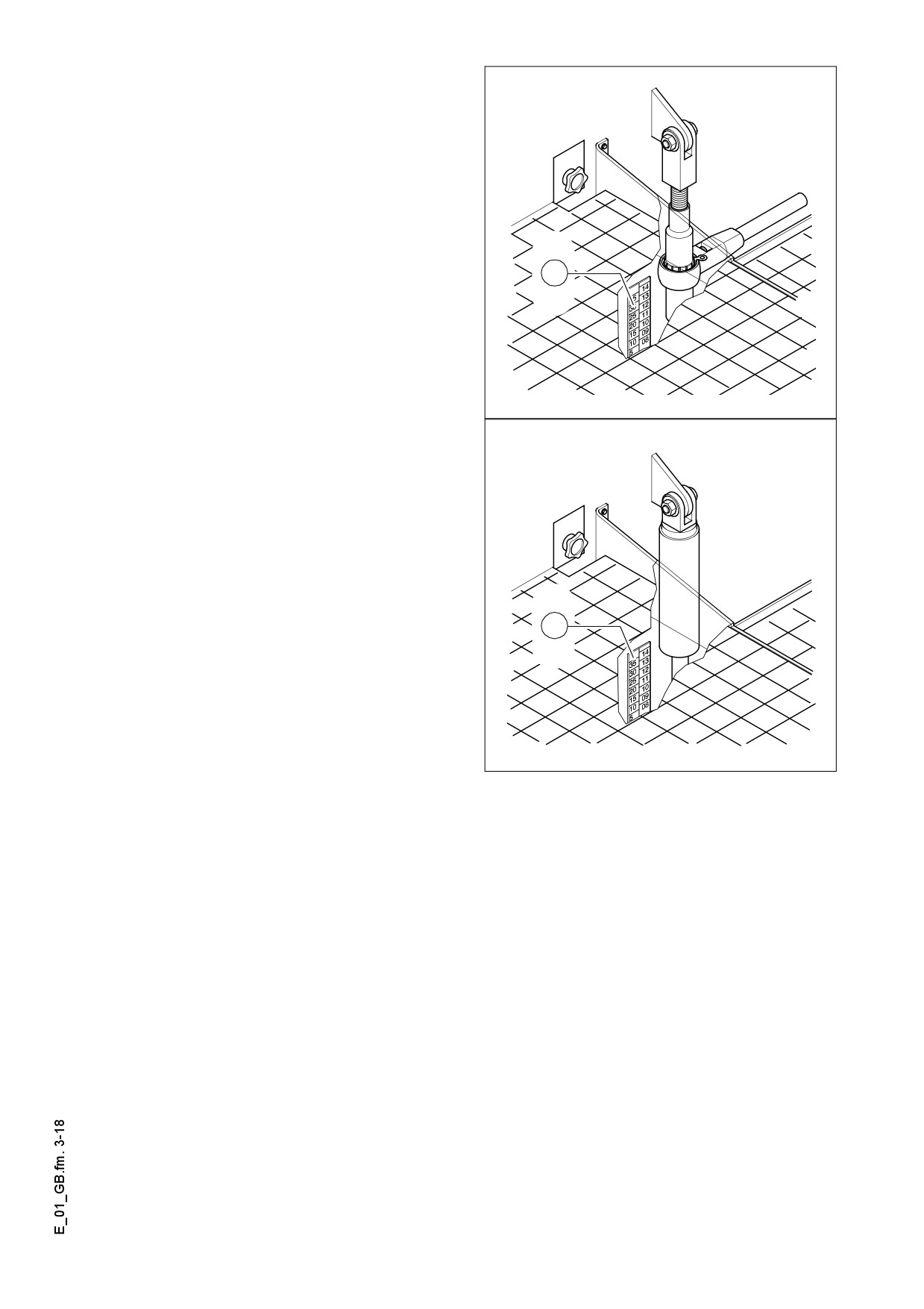
2.3
Mechanical adjustment with ratchet
(optional)
- Set the ratchet direction lever to clock-
wise or anticlockwise direction. Turn-
ing anticlockwise lowers the auger,
turning clockwise lifts the auger.
- Set the desired height by alternatingly
adjusting the right-hand and the left-
hand side.
1
- The actual height can be read on scale
(1) in cm or inch (LH side column:
inch, RH side column: inch).
F0116_A1.EPS
2.4
In case of hydraulic adjustment (op-
tion)
- Determine the currently set height of
the auger crossbeam (left and right)
by means of the scale (1).
1
F0117_A1.EPS
E 01 3
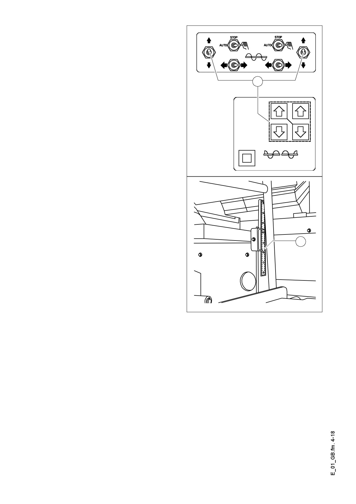
m Equally press both switches/buttons (2)
so that the auger beam does not get into
inclined position.
- Check whether the heights on the left
and on the right are identical.
2
Screedlift_konv.bmp/Screedlift_SPS.bmp
A The height indicating scales (3) may be
optionally also along the climbing rungs
on the LH/RH sides!
3
Schnskal.wmf
E 01 4
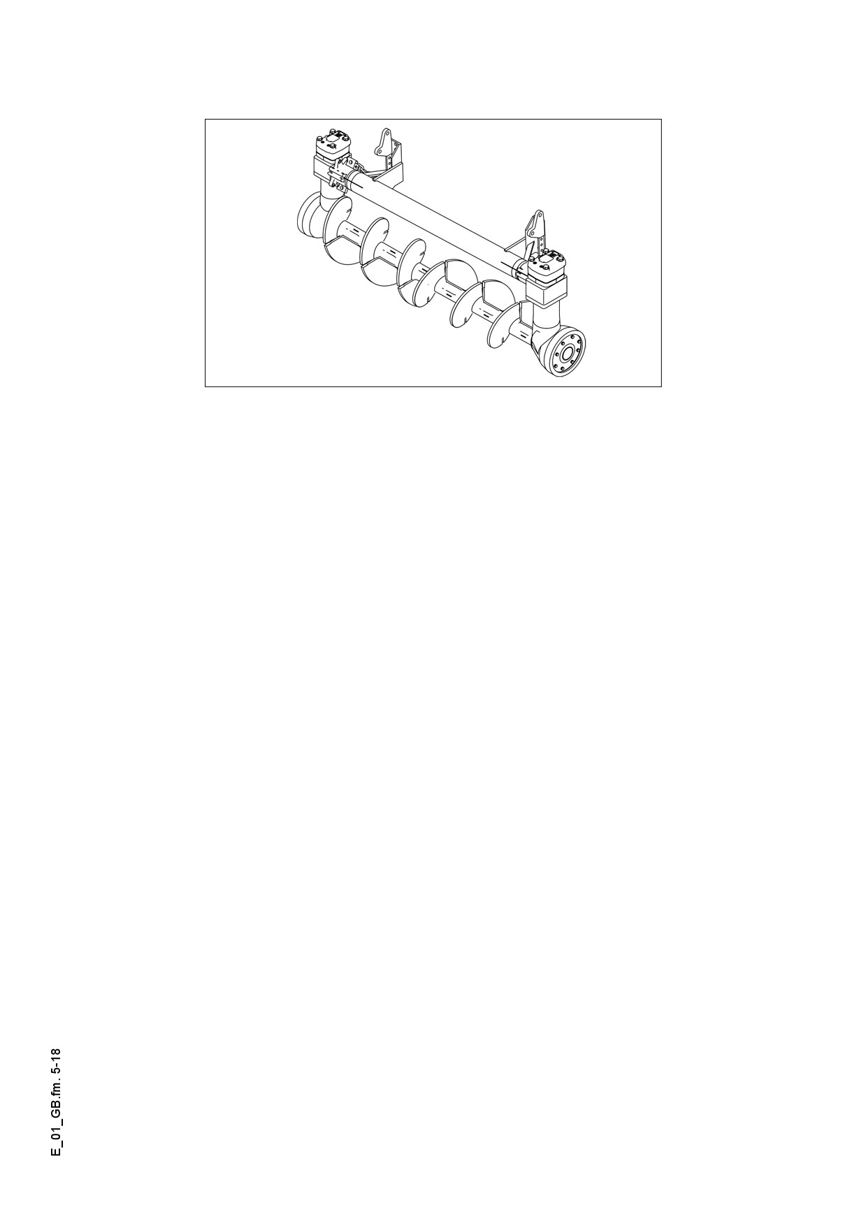
2.5
Auger extension, auger type I
Auger_Dyn.bmp
Depending on the type of screed, the most diversified working widths can be reached.
A Auger and screed extension must match. See the operating instructions of the appro-
priate screed, chapter ”Set-up and modification”, especially:
- Screed extension chart,
- Auger extension chart.
To attain the desired working width, the respective screed extensions, side plates, au-
gers, tunnel plates or cut-off shoes must be mounted.
For widths of more than 3.00 m, the auger should be fitted with extension parts on
both sides to improve material distribution and to reduce the wear.
f The diesel engine must be switched off whenever work is performed on the auger.
Danger of injuries!
E 01 5
2.6
Mounting extension parts
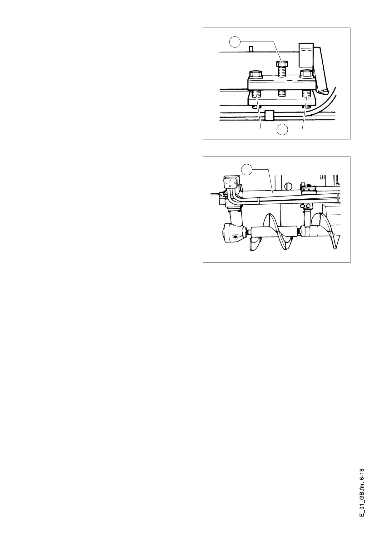
5
- Loosen the clamping screws (6) on
the support tube. Then turn in the
center expanding screw (5) to expand
the clamping joint.
6
F132_A1.TIF
- Pull the telescopic tube out of the sup-
port tube (7).
7
- Mount the required extension parts.
Observe the guide groove of the spline!
m
Make sure that the shaft end is clean!
- Slide in the telescopic tube. When do-
ing so, make sure that the drive of the
auger gear is slid all the way over the
shaft end of the auger extension part
F0133_A1.TIF
and that the threads of the augers
match.
- Remove the expansion screw (5). Then tighten the clamping screws (6). Finally
tighten the expansion screw by hand.
Before the clamping screws (6) can be tightened again, the expansion screw (5) must
m
be sufficiently turned back!
Otherwise, the telescopic tube cannot be safely clamped and the splined shaft ends
break.
When clamped insufficiently, the telescopic tube can slide out of the support tube.
f
Danger of accidents during transportation!
E 01 6
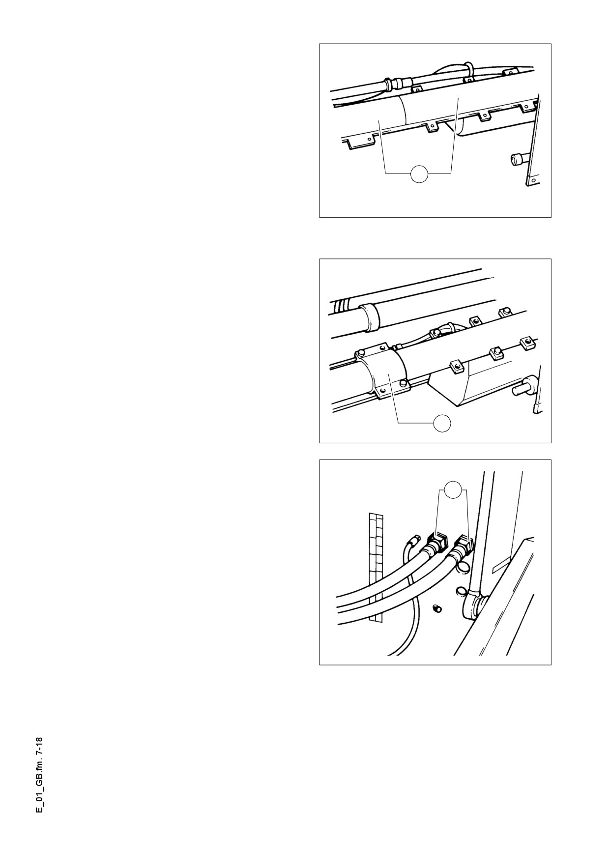
2.7
Mounting support tube extensions
If the working width exceeds 7.25 m, an
auger crossbeam extension must be
mounted.
The support tube extension of the auger
crossbeam consists of two halves (8)
and is attached to the existing support
8
tube by using a total of 5 screws. After
the two halves have been screwed to the
support tube, they also must be linked to
F0134_A1.TIF
each other by means of screwed con-
nections.
Clamping of the telescopic tube occurs
by tightening the screwed connections
(9) linking the support tube extension.
9
F0136_A1.TIF
If the working width exceeds 7.50 m the
hydraulic hoses (10) for the auger mo-
10
tors must be replaced with longer ones.
These long hoses are included in the
scope of delivery for this working width.
f When connecting or disconnecting hy-
draulic hoses, hydraulic fluid can spurt
out at a high pressure.
Switch off the paver finisher and de-
pressurize the hydraulic circuit! Protect
your eyes!
m When installing the hoses, make sure
F0135_A1.TIF
that the area around the connections is
clean.
Any dirt that enters the hydraulic system can cause malfunctions.
E 01 7
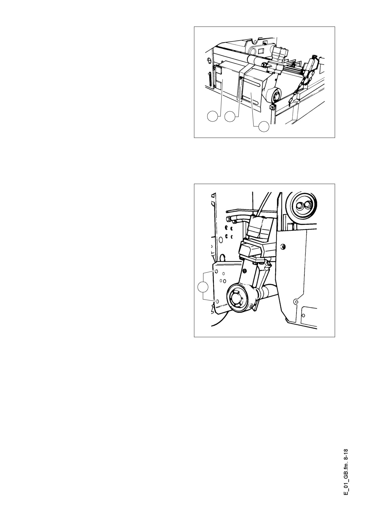
2.8
Installing tunnel plates
To ensure an optimum material flow -
especially in the case of large paving
widths
- so-called tunnel plates
(11)
must be installed.
They are located directly in front of the
auger distributor and - in conjunction
with the auger - are an ideal system for
conveying the material.
11
12
When operating with widths of more
13
than 3.90 m, two or more combined tun-
F0140_A1.TIF
nel plates (13) must be used.
In this case, additional stabilizing sup-
ports (12) must be attached to the tele-
scopic tube.
The tunnel plates must be directly
screwed to the receptacles provided for
this purpose (14); they are located on
the auger frame sides and can thus be
adjusted in height.
Refer to the auger extension chart to de-
termine which parts of the conveyor sys-
tem are required for the desired paving
width.
The auger extension chart is contained
A
14
in the operating instructions for the re-
spective screed.
F0139_A1.TIF
E 01 8
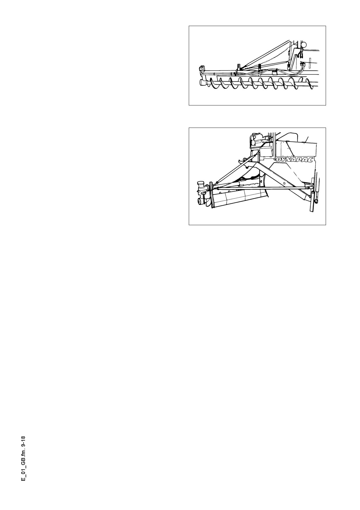
2.9
Installing additional braces
When operating with width of more than
7.25 m the augers must be provided with
an additional support.
F0141_A1.TIF
To do so, attach two braces on both the
left-hand and the right-hand side, be-
tween the tunnel plate support and the
bracket provided on the paver finisher.
The braces are included in the scope of
delivery for this working width.
F0142_A1.TIF
E 01 9
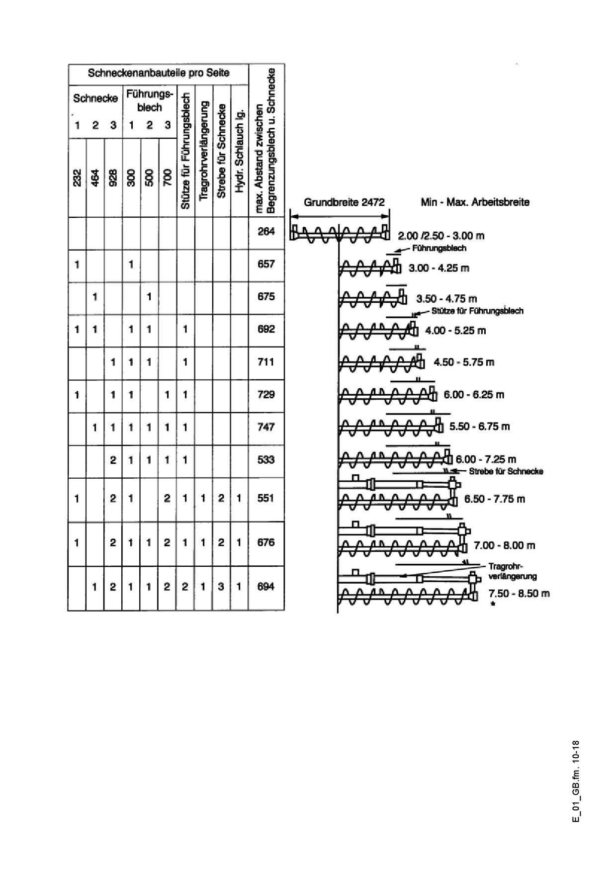
2.10
Auger mounting chart for ø 310 mm auger
* from working width of 6.75 m the machine can be operated only with appropriate
braces (screed, auger, material pipeline).
E 01 10
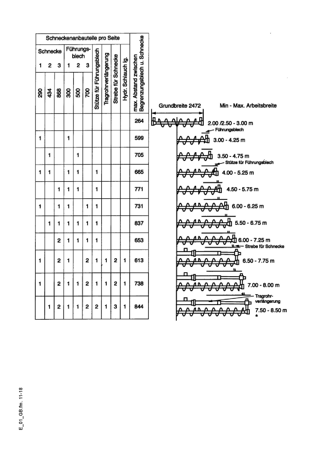
2.11
Auger mounting chart for ø 380 mm auger
* from working width of 6.75 m the machine can be operated only with appropriate
braces (screed, auger, material pipeline).
E 01 11
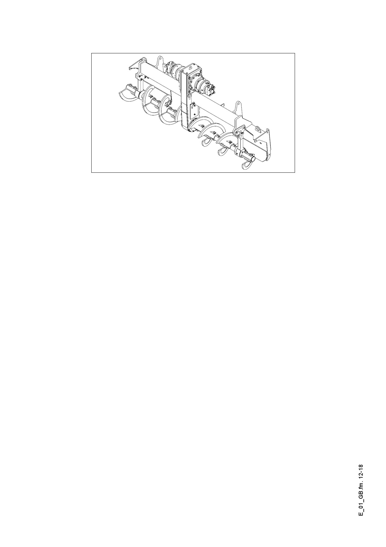
3
Auger extension, auger type II
Auger_DEM.bmp
E 01 12
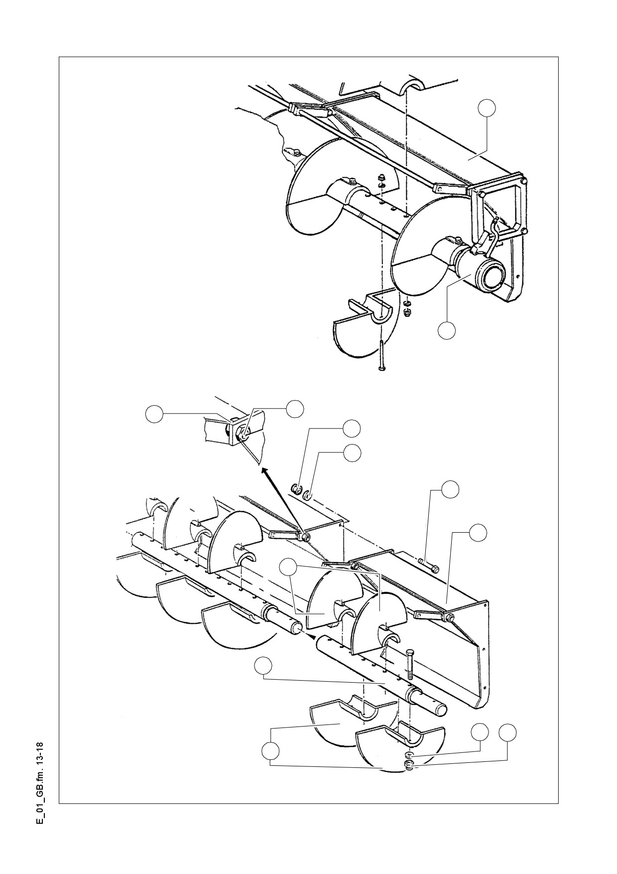
3.1
Mounting extension parts
5
16
Sch_ver1.tif
10
9
8
7
6
5
12
11
14
15
12
Sch_ver2.tif
E 01 13
- Lock the material shaft (5) with bolts (6), washers (7) and nuts (8) to the basic de-
vice.
- The material shaft can be adjusted in order to match the existing shaft.
- Loosen the nuts (9) for this and turn the sleeve (10) of bolt (6).
- Mount the extension of the auger shaft (11) on the auger shaft of the basic device.
- Fasten the auger segments (12) using bolts (13), washers (14) and nuts (15) for the
extension of the auger and simultaneously bolt the auger shafts firmly together.
A If the application conditions on the job-site allow or demand auger extension, by all
means dismount the external bearing of the auger (16), if the auger extension is long-
er than 600 mm.
When extending the auger on the basic device with external auger bearing, the short-
er auger segment shall be mounted on the bearing. In the opposite case, both the au-
ger segment and the bearing may get damaged, when paving with 30 mm aggregate.
E 01 14
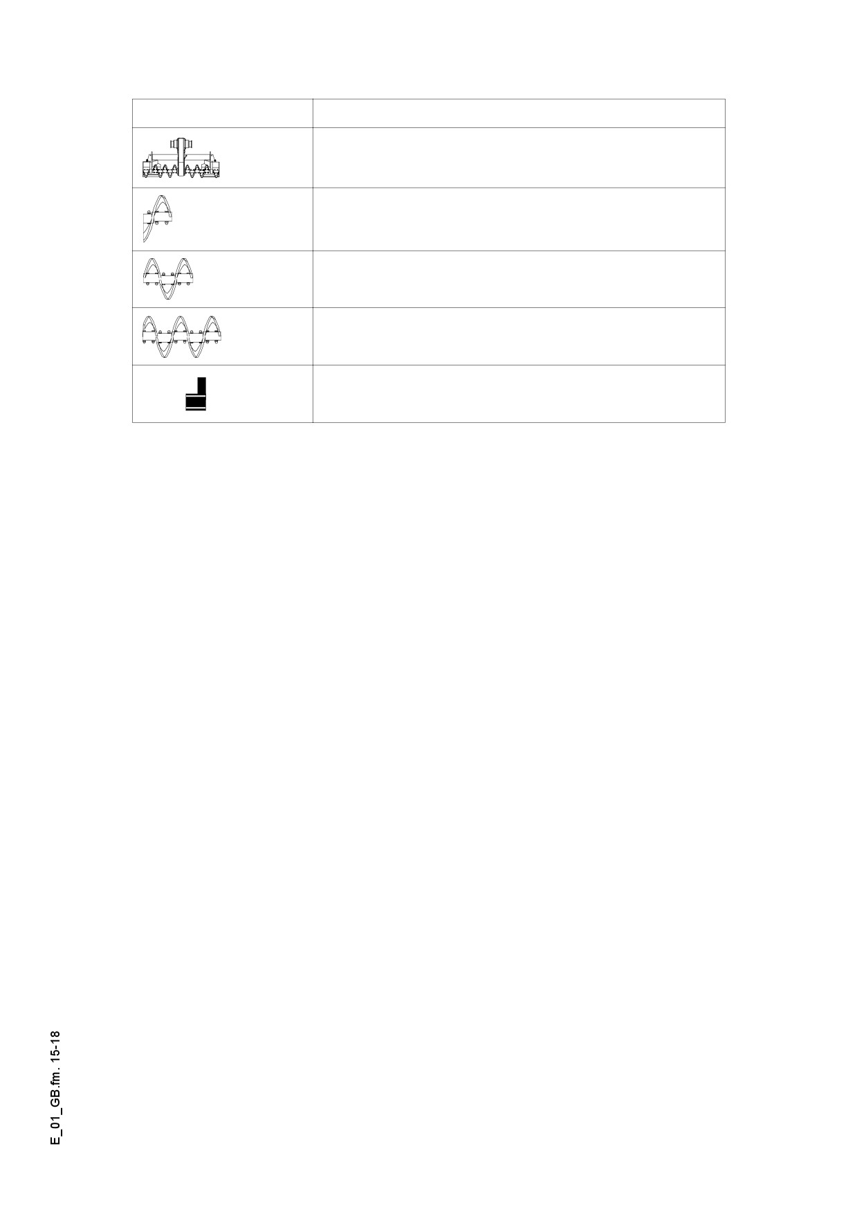
3.2
Auger modification plan.
Marking
Meaning
Basic auger
Auger section to be mounted +
material shaft 320mm
Auger section to be mounted +
material shaft 640mm
Auger section to be mounted +
material shaft 960mm
Auger - outer bearing
E 01 15
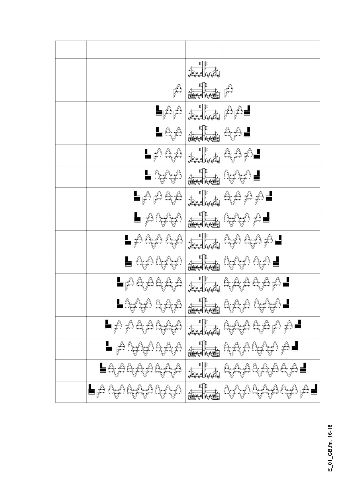
Paving
Mountable parts / bearing
Mountable parts / bearing
width
2.5 m
- 3.7 m
3.2 m
- 4.4 m
4.1 m
- 5.0 m
4.1 m
- 5.0 m
4.8 m
- 5.7 m
4.8 m
- 5.7 m
5.4 m
- 6.3 m
5.4 m
- 6.3 m
6.0 m
- 6.9 m
6.0 m
- 6.9 m
6.7 m
- 7.6 m
6.7 m
- 7.6 m
7.3 m
- 8.2 m
7.3m
- 8.2 m
8.0 m
- 8.9 m
8.6 m
- 9.6 m
E 01 16
4
Screed
The operating instructions for the screed cover all work required for mounting, setting
up and extending the screed.
5
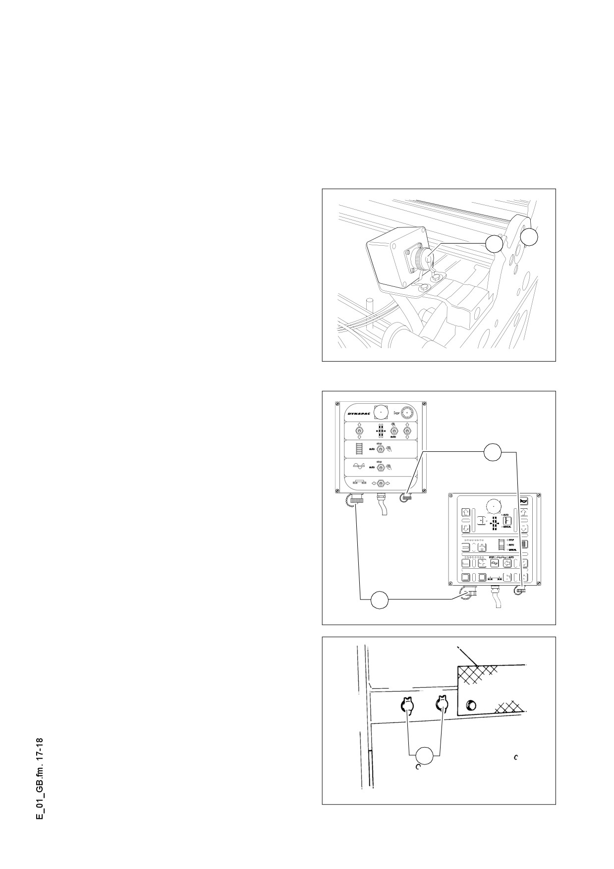
Electrical connections
Establish the following connections when the mechanical components have been
mounted and set up:
5.1
Remote controls
to socket (15) (on the screed).
17
15
Socket.bmp
5.2
Grade control
to socket (16) (on the remote control
unit)
17
5.3
Auger limit switches
to socket (17) (on the remote control
unit)
16
F0119_A1.TIF
5.4
Working lights
to sockets (18) (on the paver finisher).
18
F0124_A1.TIF
E 01 17
F 1.0
Maintenance
1
Notes regarding safety
Maintenance work: Maintenance work may only be carried out when the engine is
f
at a standstill.
Secure the paver finisher and the attachments against inadvertent starting before be-
ginning any maintenance work:
- Set the drive lever to the center position and the speed preselector to zero.
- Remove the ignition key and the battery main switch.
Lifting and jacking up: Secure lifted machine parts (e.g. screed or hopper) against
f
lowering by means of mechanical supports.
Spare parts: Use only approved parts and install them according to the specifica-
m
tions! If in doubt, contact the manufacturer!
Re-commissioning: Mount all protective devices before re-commissioning the paver
f
finisher.
Cleaning: Cleaning must not be carried out while the engine is running.
f
Do not use any inflammable substances (such as petrol).
Avoid directly cleaning electrical parts and insulation material with a steam jet; cover
them up beforehand.
Working in closed environments: Exhaust fumes must be led into the open. Pro-
f
pane gas bottles must not be stored in closed rooms.
In addition to these Maintenance Instructions, the Maintenance Instructions of the en-
m
gine manufacturer must always also be observed. All other maintenance work and in-
tervals noted in these instructions are also binding.
The instructions for the maintenance of the optional equipment are included in the
A
sub-chapters of this chapter.
F 1.0 1
F 2.4
Maintenance overview
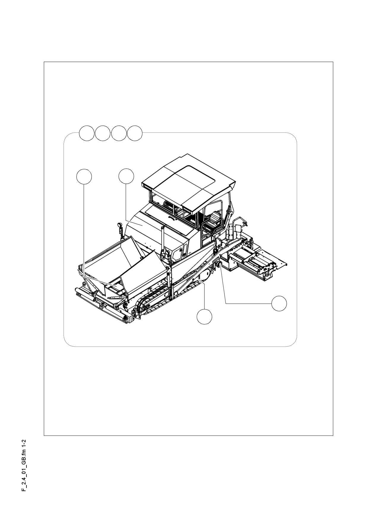
1
Maintenance review
6
8
9
10
3
5.1
4.2
7.1
F 2.4 1
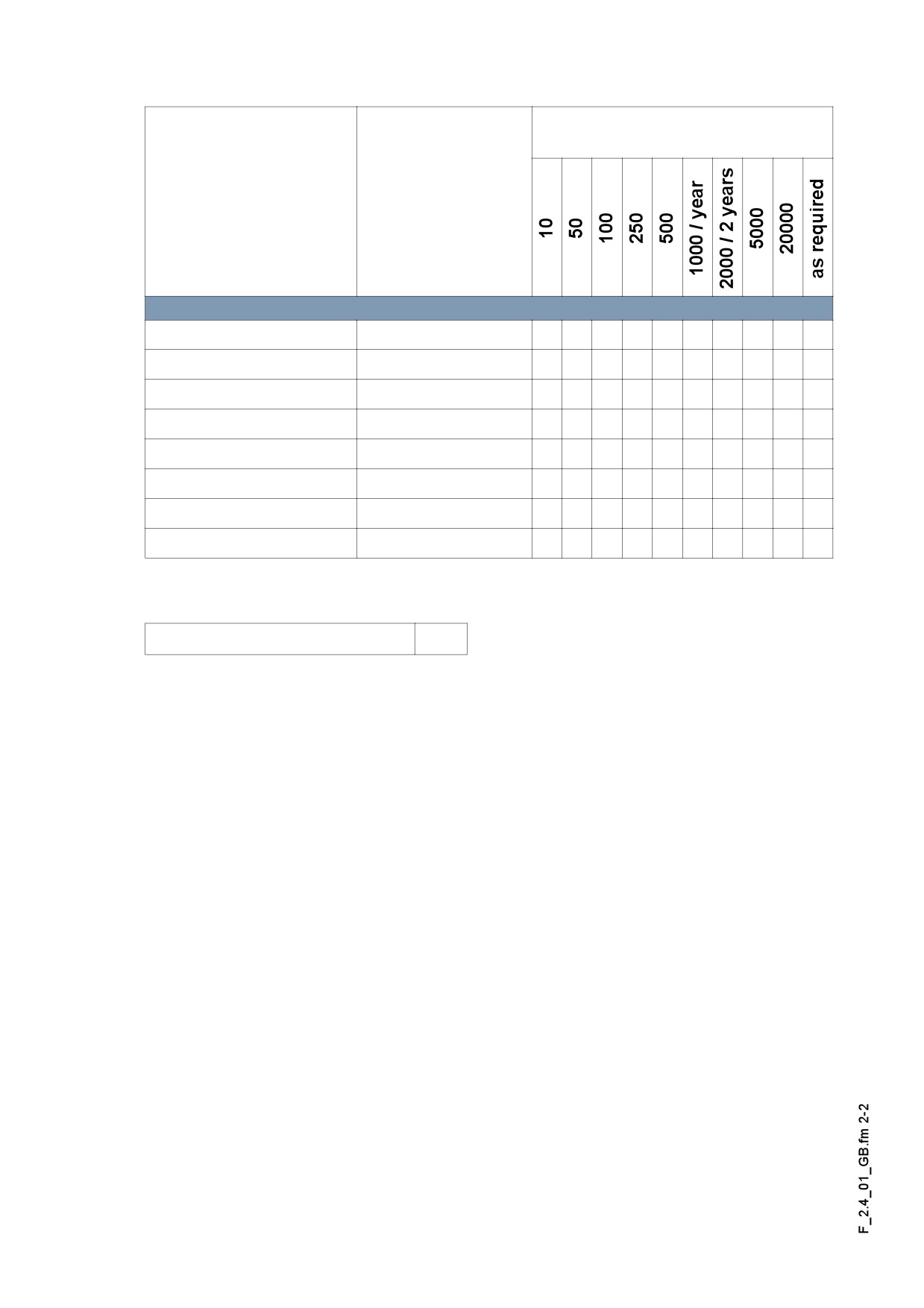
Maintenance required after the
following service hours.
Sub-units
Chapter
Feeder
F3
q
q
q
q
Auger
F4.2
q
q
q
q
q
q
Drive engine
F5.1
q
q
q
q
q
q
Hydraulics
F6.0
q
q
q
q
q
q
Track
F7.1
q
q
q
q
Electronics
F8
q
q
q
q
q
q
q
Lubrication points
F9
q
q
q
q
Checking/stopping
F10
q
q
q
Maintenance required
q
A This review also includes the maintenance intervals of the optional equipment of the
machine!
F 2.4 2
F 3.0
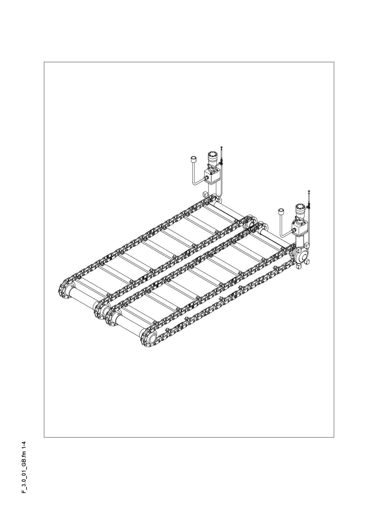
Maintenance - Conveyor
1
Maintenance - Conveyor
F 3.0 1
1.1
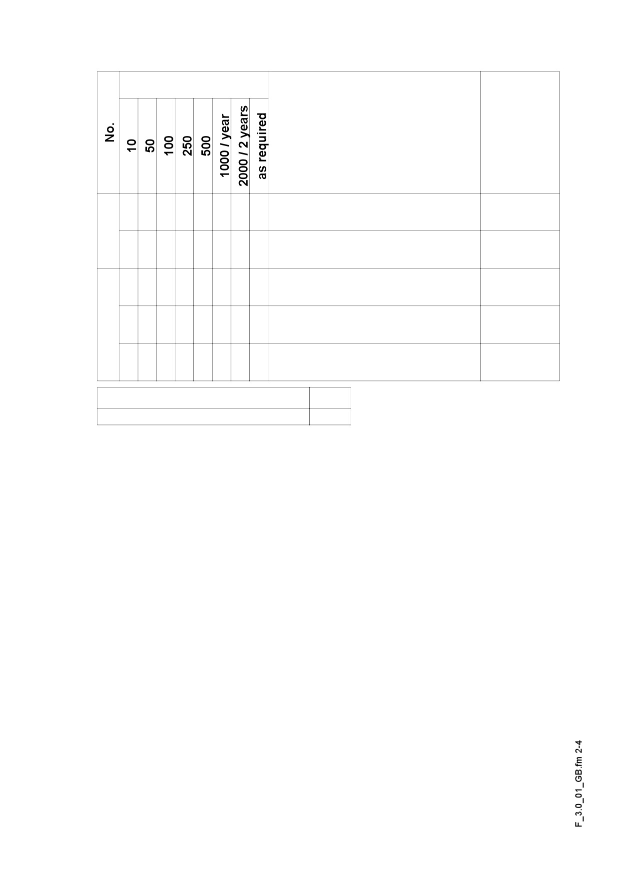
Maintenance intervals
Interval
Points of maintenance
Remark
- Checking the tightness of the
q
conveyor chain
1
- Adjustment of the tightness of the
q
conveyor chain
- Checking the oil level of the
q
conveyor drive
- Topping up the oil level of the
2
q
conveyor drive:
- Changing the oil of the
q
conveyor drive
Maintenance
q
Maintenance during run-in period
g
F 3.0 2
1.2
Points of maintenance
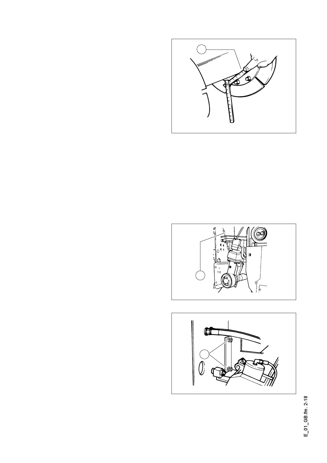
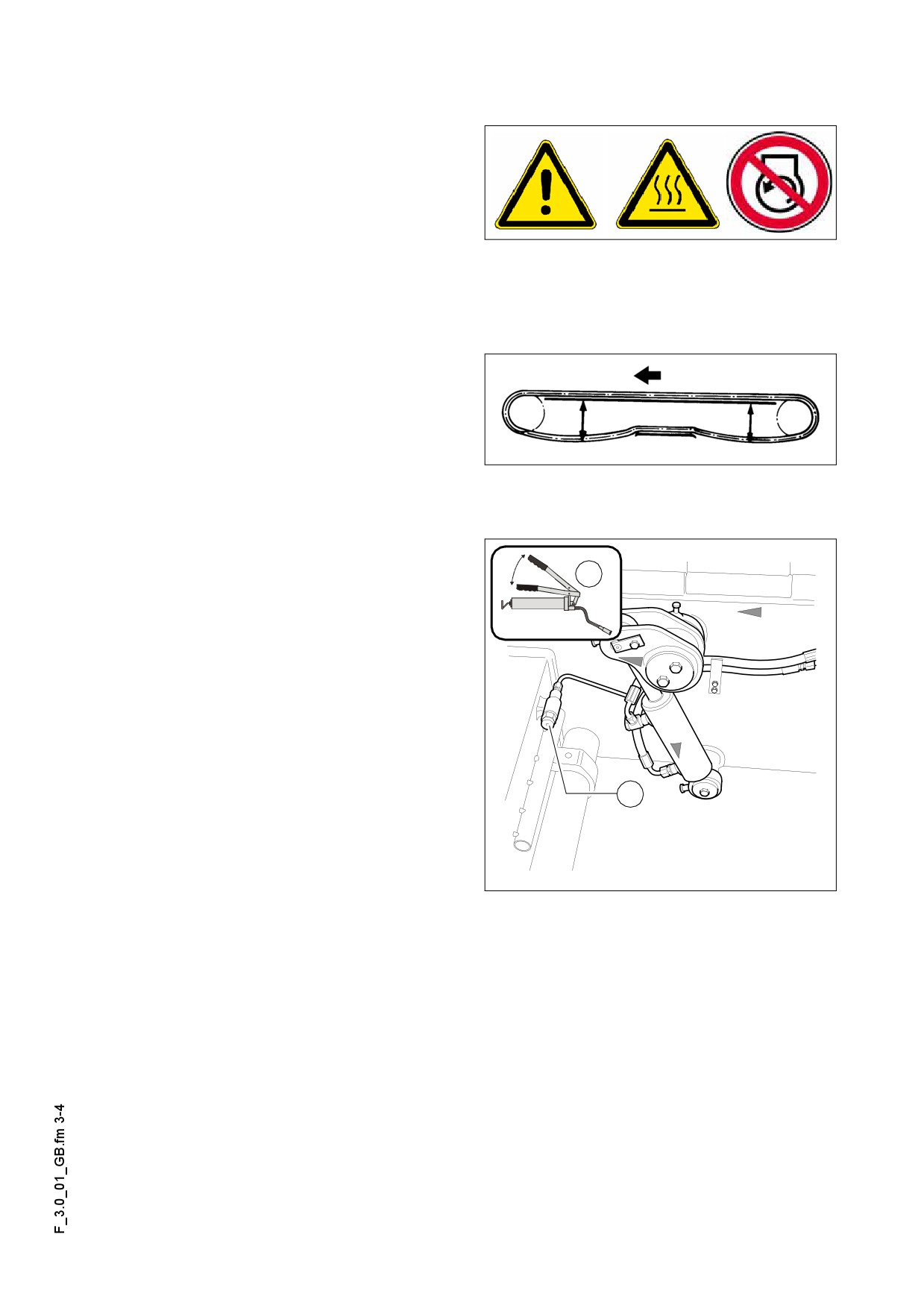
Chain tightness of the conveyor (1)
Checking the chain tightness:
For daily inspection look straight through
under the bumper. The chain must not
hang below the bottom edge of the bumper.
Should readjustment be necessary, measure the slack unladen from the bottom edge
of the floor plate until the lower edge of the chain (see the figure).
The chains should not be too tight or too
m
slack. Material between the chains and
the sprocket wheel can lead to stoppage
280
280
or breakage, in case of too tight chains.
If the chain is too slack, it may get stuck
F0159_A1.TIF
in the protruding objects and be dam-
aged.
Adjustment of chain tightness:
x
The chain tightness can be adjusted with
A
grease press. The filling ports (A) are lo-
cated behind the bumper on the RH and
LH sides.
A
Conveyor_set.eps
F 3.0 3
The drive of conveyor (to the left/to
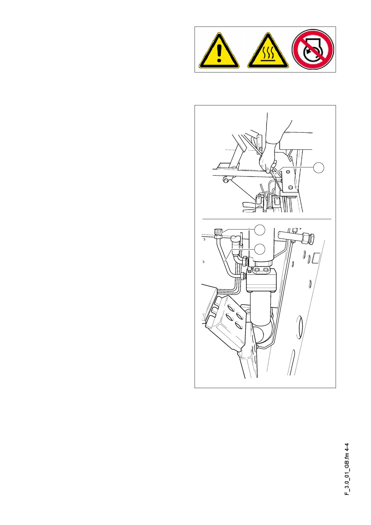
the right) (2)
The drive unit of the conveyor is under
the floorboard of the operating position.
Checking the oil level Only before the
work starts. The oil level must reach the upper notch of the dipstick (A).
Filling in the oil: After removing cover lid (B) through fill-in stub (C).
On the dipstick about
10 cm corre-
A
sponds to about 0,25 l oil to be added.
The drive of the conveyor is filled in the
factory with Optimol Optigear 220 oil.
Owing to the excellent quality of the oil
filled in, there is no need for regular oil
change.
It is sufficient to regularly check the oil
A
level in the drive (see chapter of mainte-
nance intervals).
The above applies only if Optimol Op-
m
tigear 220 or oil of a similar quality from
another manufacturer is used.
B
C
F0151_A1.TIF/F0152_A1.TIF
F 3.0 4
F 4.2
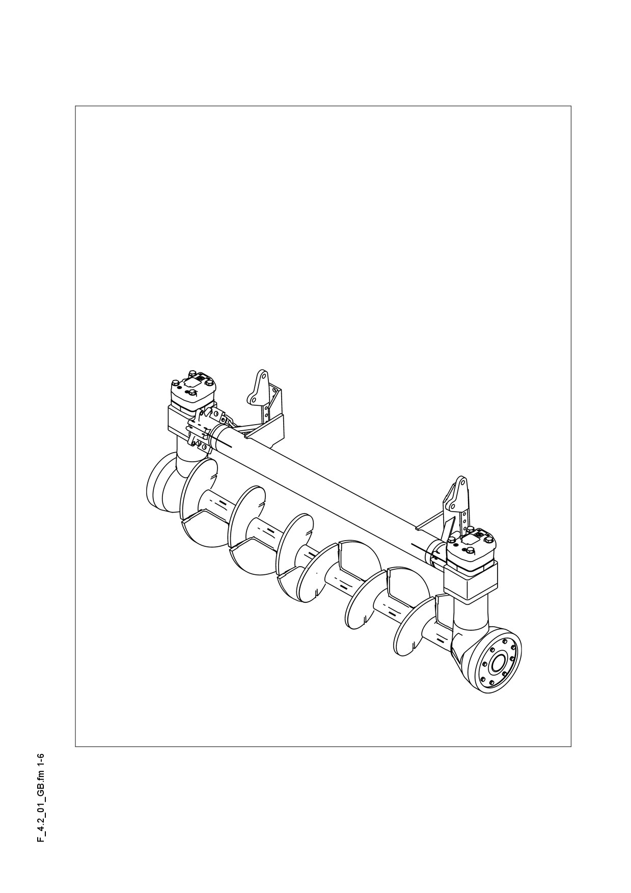
Maintenance - Auger
1
Maintenance - Auger sub-unit I
F 4.2 1
1.1
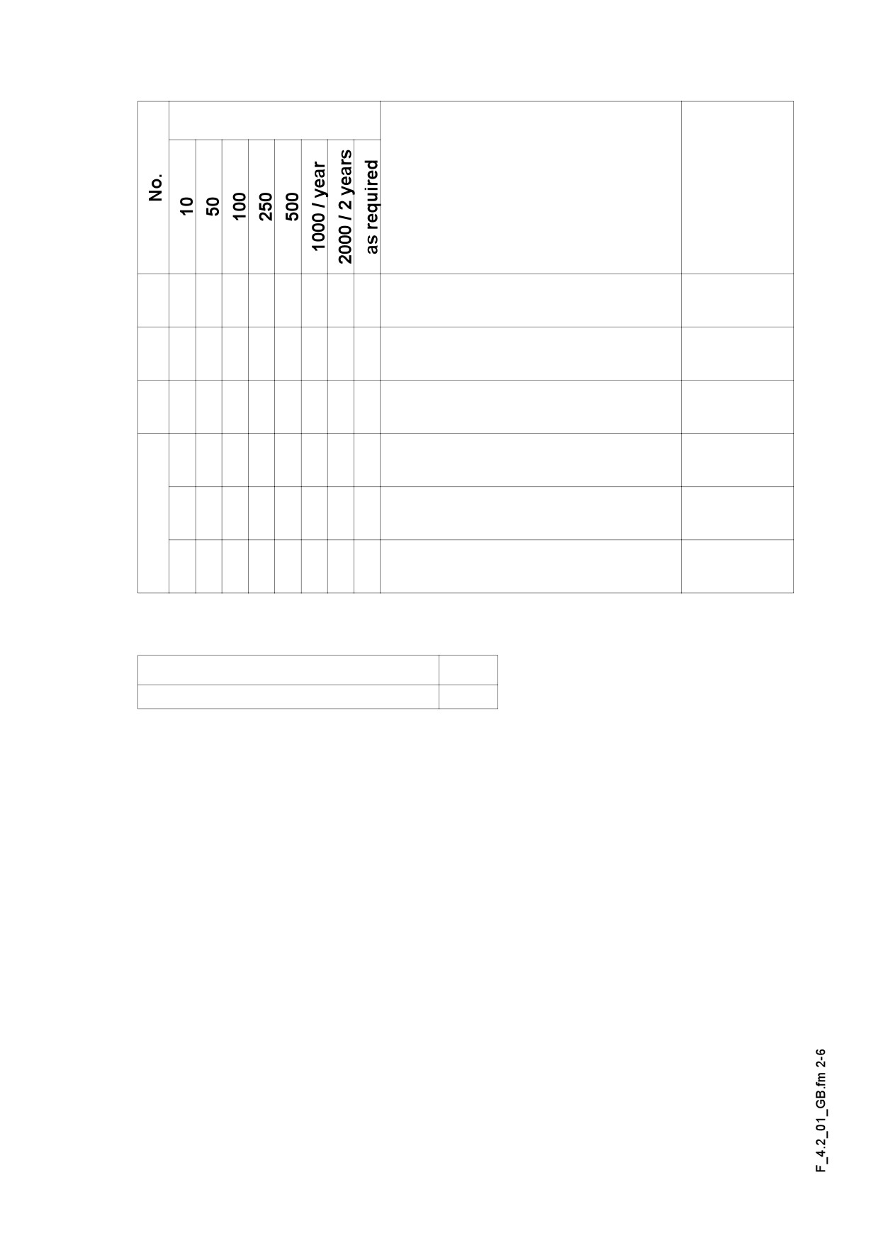
Maintenance intervals
Interval
Points of maintenance
Remark
- Auger - outer bearing
1
q
Lubrication
- Auger central bearing
2
q
Lubrication
- Auger drive neck bearing
3
q
Lubrication
- Auger bevel gear
q
oil level check
- Auger bevel gear
4
q
topping up the oil
- Auger bevel gear
q
oil change
Maintenance
q
Maintenance during run-in period
g
F 4.2 2
1.2
Points of maintenance
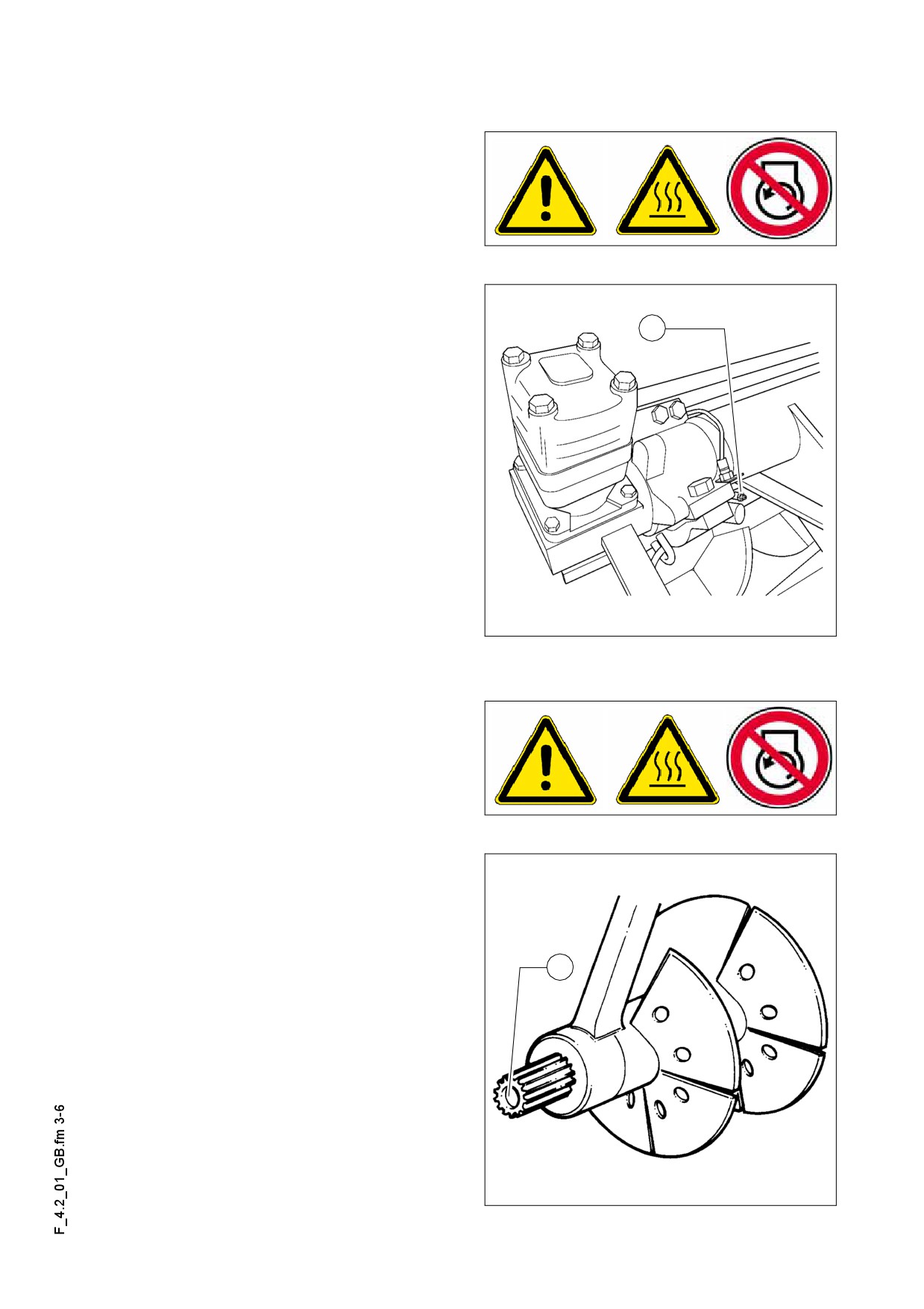
Auger - outer bearing (1)
The grease nipples (A) are located on
each side on the top of outer bearing.
These nipples must be lubricated each
time when work is finished.
A The outer bearings of the auger shall be
lubricated when hot, so that the eventual
A
bitumen residues are expelled.
Schneckaula_Dyn.tif
Auger middle bearing (2)
Lubrication of central bearing (A) is per-
formed on the LH-side of the auger.
To do so, the bevel gear unit must be
pulled off.
A The central bearing shall be lubricated
when hot, so that the eventual bitumen
residues are expelled.
A
F0015_A1.TIF
F 4.2 3
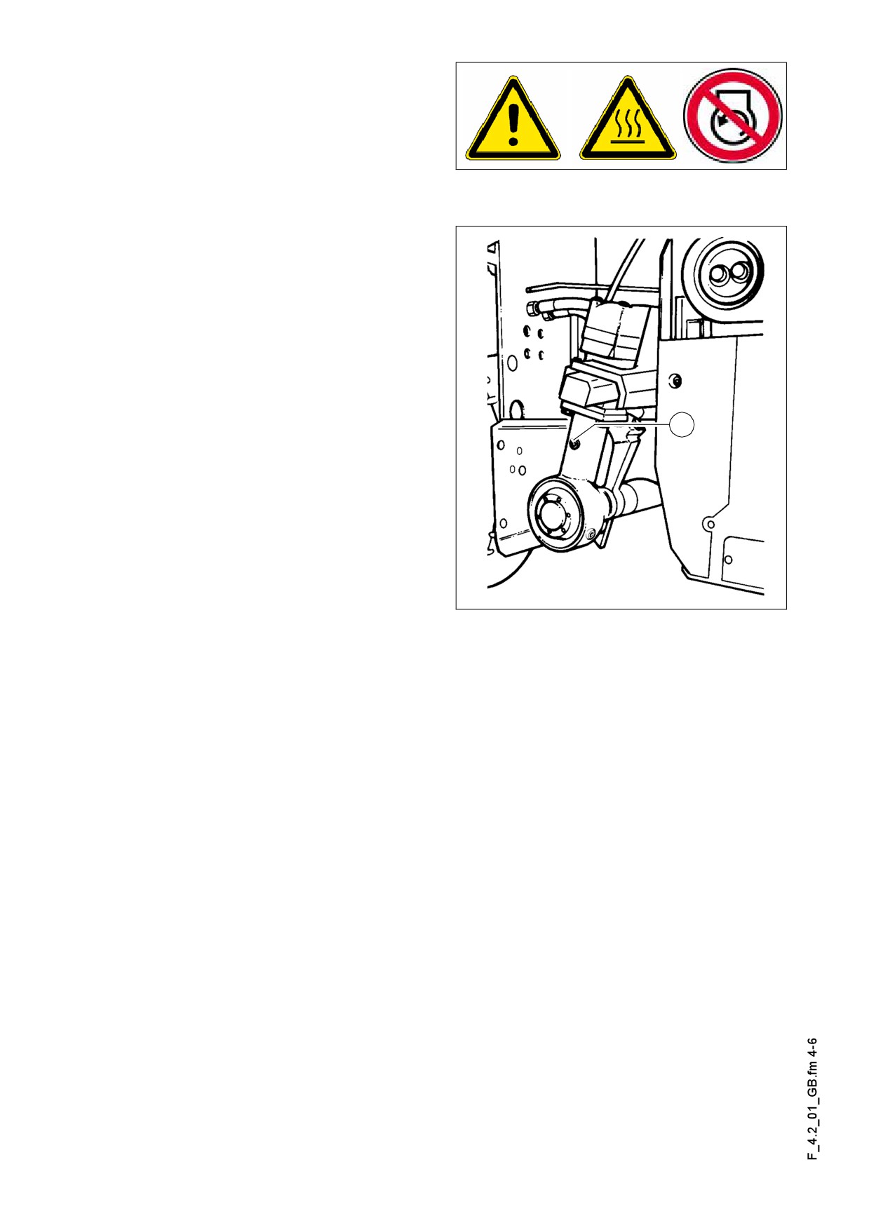
Auger - drive gear neck bearing (3)
Remove the hexagonal screw plug (A) in
the neck of the drive. Replace the screw
under it with a grease nipple 10x1. Using
a grease gun press in about 10 strokes
of grease.
A Thereafter, unscrew the grease nipple
and drive in both screws. The neck of the
drive is sealed downwards and is lubri-
cated with grease only.
A
F0139_A1.TIF
F 4.2 4
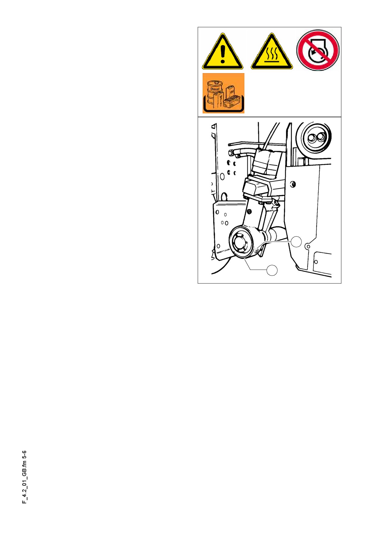
Auger bevel gear (on the RH and LH
sides) (4)
- For checking the oil level unscrew
the inspection / filling plug (A).
In case of proper oil level, the oil is at the
A
lower edge of the inspection port or a lit-
tle oil flows from the hole.
For filling in the oil:
- Remove the inspection / filling plug
(A).
- Fill oil of the correct specification
through the filling hole (A) until the oil
level reaches the lower edge of the in-
spection hole (A).
- Replace the inspection / filling plug
(A).
For changing the oil:
Change the oil when the engine is at op-
A
A
erating temperature.
- Remove the inspection / filling plug (A)
B
and the drain plug (B).
F0139_A1.TIF
- Drain the oil.
- Drive in the oil drain plug (C) again.
- Fill oil of the correct specification through the filling hole (A) until the oil level reach-
es the lower edge of the inspection hole (A).
- Replace the inspection / filling plug (A).
Take care of cleanliness!
m
F 4.2 5