SuperBlade Server SBS-820H-420P. USER’S MANUAL (Revision 1.0) - page 3
Chapter 8: Blade Software
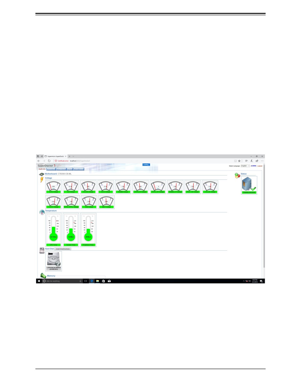
8.3 SuperDoctor® 5
The Supermicro SuperDoctor 5 is a program that functions in a command-line or web-based
interface for Windows and Linux operating systems. The program monitors such system health
information as CPU temperature, system voltages, system power consumption, fan speed,
and provides alerts via email or Simple Network Management Protocol (SNMP).
SuperDoctor 5 comes in local and remote management versions and can be used with Nagios
to maximize your system monitoring needs. With SuperDoctor 5 Management Server (SSM
Server), you can remotely control power on/off and reset chassis intrusion for multiple systems
with SuperDoctor 5 or the BMC. SuperDoctor 5 Management Server monitors HTTP, FTP,
and SMTP services to optimize the efficiency of your operation.
SuperDoctor® Manual and Resources
Figure 8-4. SuperDoctor 5 Interface Display Screen (Health Information)
80
Chapter 8: Blade Software
8.4 BMC
The motherboard provides remote access, monitoring and management through the
baseboard management controller (BMC) and other management controllers distributed
among different system modules. There are several BIOS settings that are related to BMC.
For general documentation and information on BMC, visit our website at:
BMC ADMIN User Password
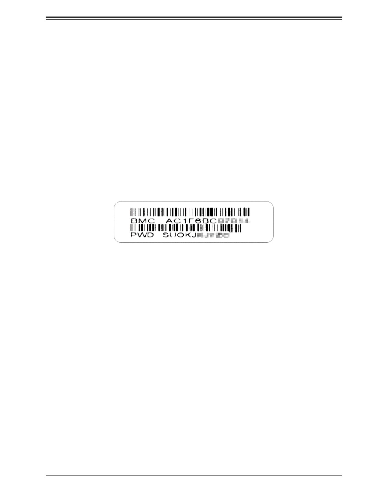
For security, each system is assigned a unique default BMC password for the ADMIN user.
This can be found on a sticker on the chassis and a sticker on the motherboard. The sticker
also displays the BMC MAC address. If necessary, the password can be reset using the
Supermicro IPMICFG tool.
Figure 8-5. BMC Password Label
The sticker can be found on the pull-out service tag at the front of the chassis. See Chapter
1 for the location.
81
Chapter 9: Optional Components
Chapter 9
Optional Components
This chapter describes optional system components.
9.1 TPM Security Module
SPI capable TPM 2.0 (or 1.2) with Infineon 9670 controller, Horizontal form factor
The JTPM1 header is used to connect a Trusted Platform Module (TPM). A TPM is a security
device that supports encryption and authentication in hard drives. It enables the motherboard
to deny access if the TPM associated with the hard drive is not installed in the system.
Details and installation procedures are at:
https://www.supermicro.com/manuals/other/TPM.pdf.
82
Chapter 9: Optional Components
9.2 Intel Virtual RAID on CPU (VROC)
Intel® Virtual RAID on CPU (Intel VROC) is an enterprise RAID solution for NVMe SSDs
directly attached to Intel Xeon Scalable processors. Intel Volume Management Device (VMD)
is an integrated controller inside the CPU PCI-E root complex.
• A single processor supports up to 12 NVMe SSDs and up to 6 RAID arrays.
• A dual processor system supports up to 24 NVMe SSDs and 12 RAID arrays.
Strip sizes are 4K, 8K, 16K, 32K, 64K, 128K.
Requirements and Restrictions
• Intel VROC is only available when the system is configured for UEFI boot mode.
• To enable the mdadm command and support for RSTe, install the patch from
tel-VROC-and-Intel-Rapid-Storage-Technology-enterprise-Intel-RSTe-Driver-for-Linux-
CPU-Intel-VROC-and-Intel-Rapid-Storage-Technology-enterprise-Intel-RSTe-Driver-for-
Windows-
• To enable Intel VROC, a hardware key must be inserted on the motherboard, and the ap-
propriate processor’s Virtual Management Devices must be enabled in the BIOS setup.
• It is possible to enable Intel VROC without a hardware key installed, but only RAID0 will
be enabled.
• Intel VROC is not compatible with secure boot. This feature must be disabled.
• When creating bootable OS RAID1 devices, you must have both devices on the same
CPU, and a VMD on that CPU.
• Spanning drives when creating RAID devices is not recommended to due to performance
issues, even though it is supported.
Supported SSDs and Operating Sytems
To see the latest support information: https://www.intel.com/content/www/us/en/support/
articles/000030310/memory-and-storage/ssd-software.html
83
Chapter 9: Optional Components
Additional Information
Additional information is available on the product page for the Supermicro add-on card and
the linked manuals.
Hardware Key
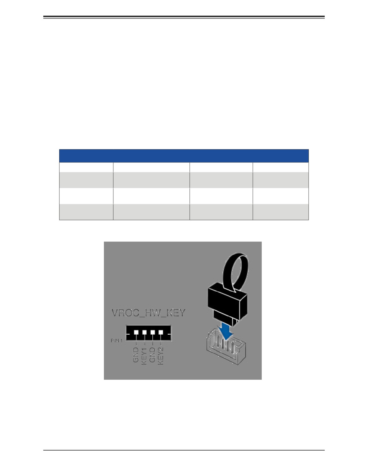
The Intel VROC hardware key is a license key that detects the Intel VROC SKU and
activates the function accordingly. The key must be plugged into the Supermicro motherboard
(connector JRK1). The key options are:
Intel® VROC Keys
VROC Package
Description
Part Number
Intel MM Number
RAID 0, 1, 10
Standard
AOC-VROCSTNMOD
951605
Supports 3rd party SSDs
RAID 0, 1, 5, 10
Premium
AOC-VROCPREMOD
951606
Supports 3rd party SSDs
RAID 0, 1, 5, 10
Intel SSD only
AOC-VROCINTMOD
956822
Supports Intel SSDs only
Figure 9-1. Intel VROC RAID Key and Motherboard Connector JRK1
84
Chapter 9: Optional Components
Configuring NVMe RAID Manually
RAID for NVMe SSDs is enabled by default when Intel VROC Raid Key is populated. It may
be managed manually through the UEFI BIOS.
1. Reboot the server and press [DEL] key to access the BIOS options.
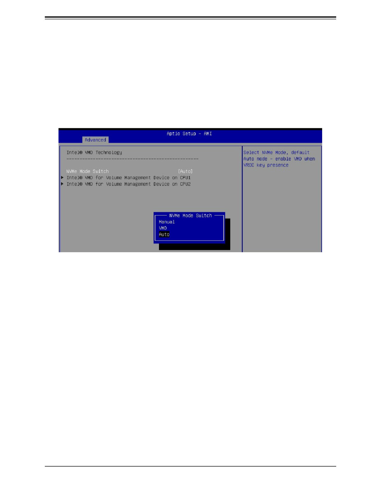
2. Switch to Advanced > Chipset Configuration > North Bridge > IIO Configuration >
Intel® VMD Technology.
Figure 9-2. BIOS, Selecting VMD Mode
You can select a mode. The default is Auto. The VMD switch enables VMD mode for all
NVMe ports despite the presence of the VROC key. The Manual switch allows the user to
choose devices on which to enable VMD.
The onboard M.2 NVMe from PCH is located in the CPU1 section.
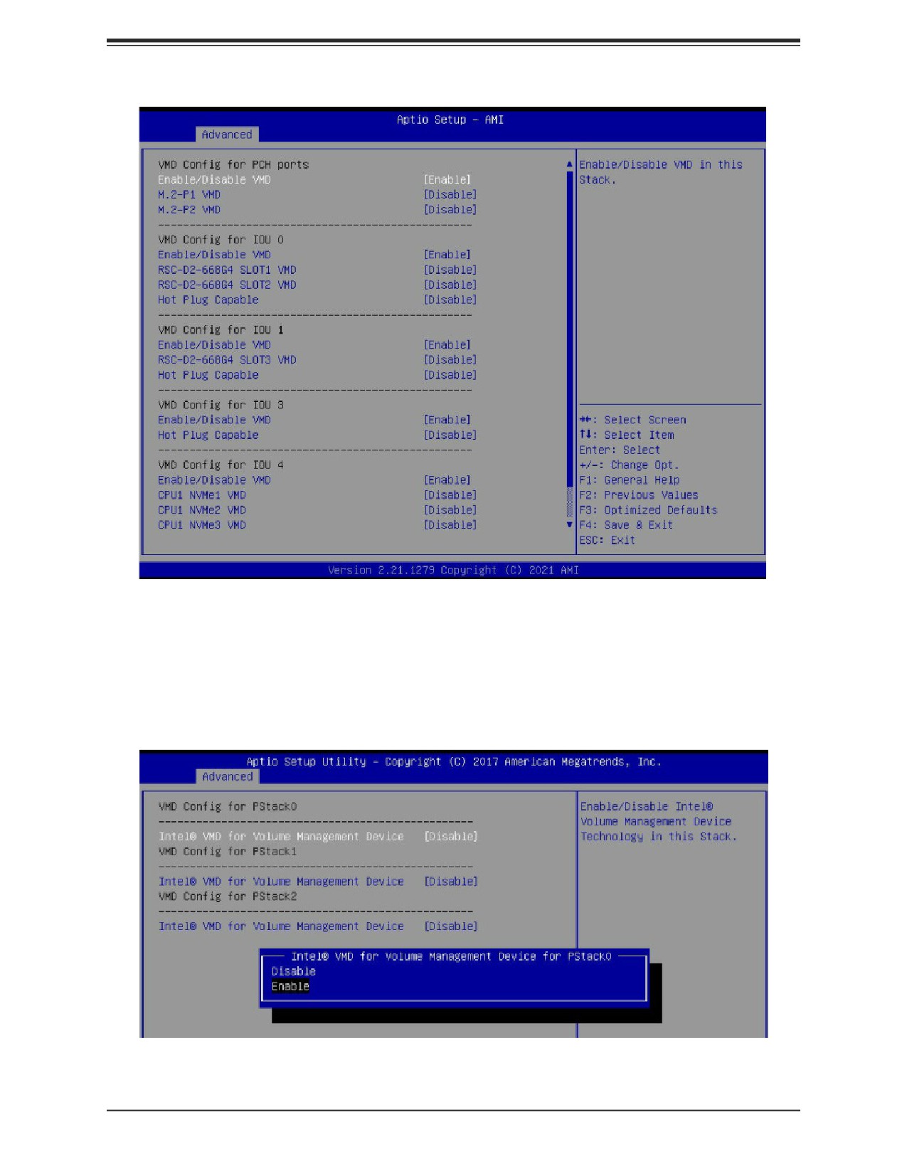
The screenshot below show example choices in Manual mode.
85
Chapter 9: Optional Components
Figure 9-3. BIOS, Manual Mode (Example—your server may look different.)
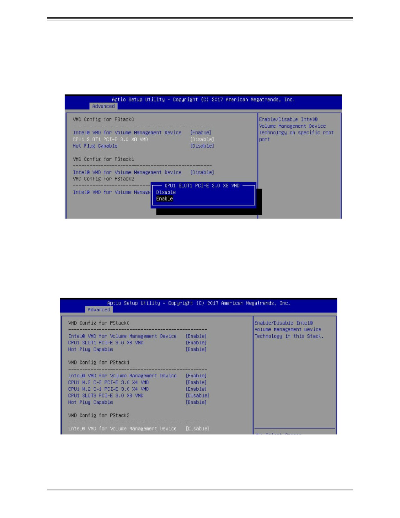
3. Select the desired PStack# to Enable or Disable the corresponding Intel VMD controller
Figure 9-4. BIOS, Enabling VMD for Pstack0
86
Chapter 9: Optional Components
4. Select the desired PCIe slot to Enable or Disable Intel VMD functionality according to
the current hardware configuration being used. Hot Plug Capability can also be Enabled
or Disabled.
Figure 9-5. BIOS, Enabling VMD Functionality per Slot
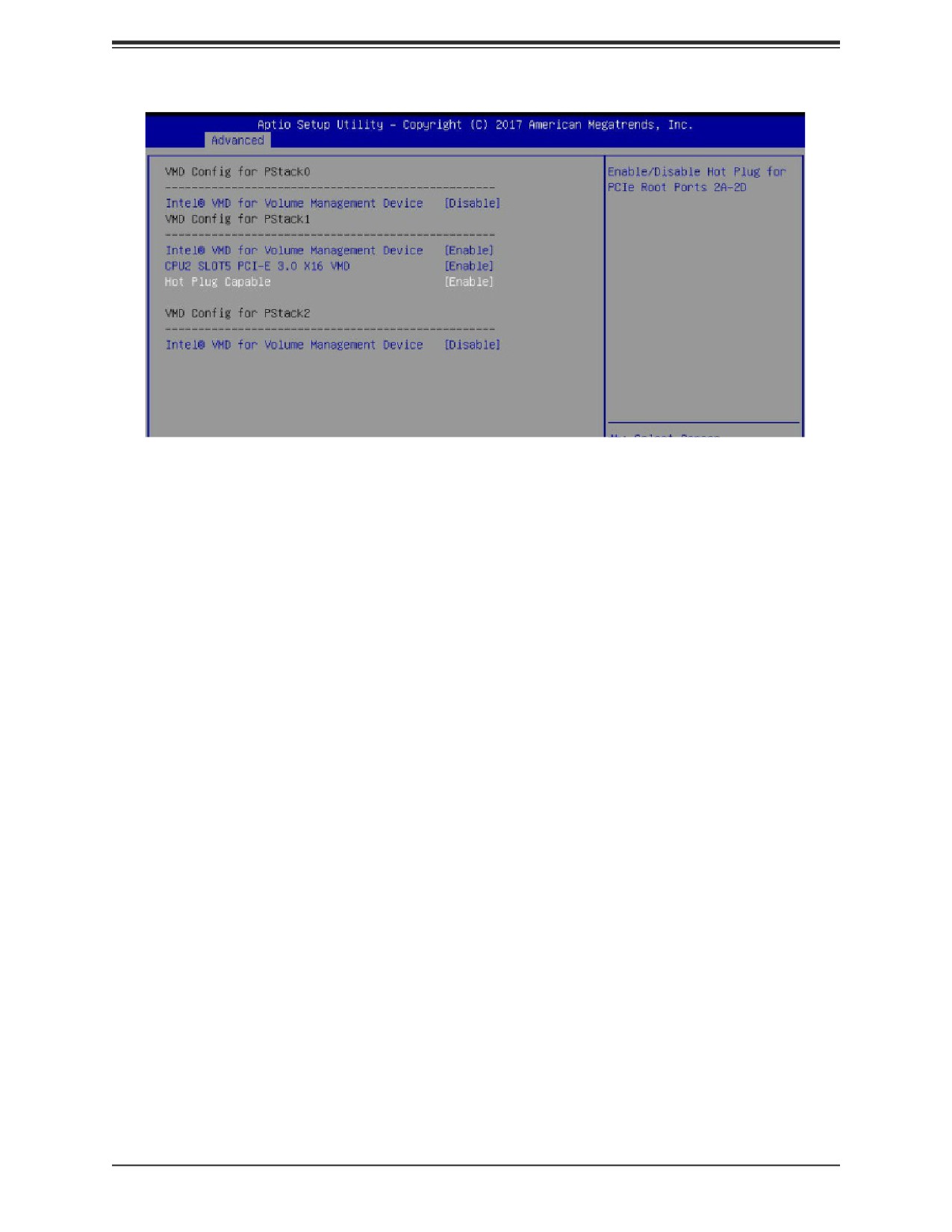
5. Repeat steps 3 and 4 for each PStack# on each CPU to be enabled or disabled. In this
example, we enabled CPU1 Slot1 (Figure 6-11) and CPU2 Slot5 (Figure 6-12) (four U.2
form factor SSDs), as well as CPU1 M.2 C-1 and CPU1 M2. C-2 (two M.2 form factor
SSDs)
Figure 9-6. BIOS, Enabling CPU1 Example
87
Chapter 9: Optional Components
Figure 9-9. BIOS, Enabling CPU2 Example
6. Press [F4] to save the configuration and reboot the system and press [DEL] to enter
BIOS.
Note: Disabling the VMD controller without first deleting the associated existing RAID
volume can lead to unexpected behavior. This action is strongly not recommended.
Note: The effects of physically changing or swapping a CPU on the VMD controller
enablement has not yet been thoroughly tested or documented.
7. Switch to Advanced > Intel(R) Virtual RAID on CPU > All Intel VMD Controllers >
Create RAID Volume.
8. Set Name.
9. Set RAID Level.
88
Chapter 9: Optional Components
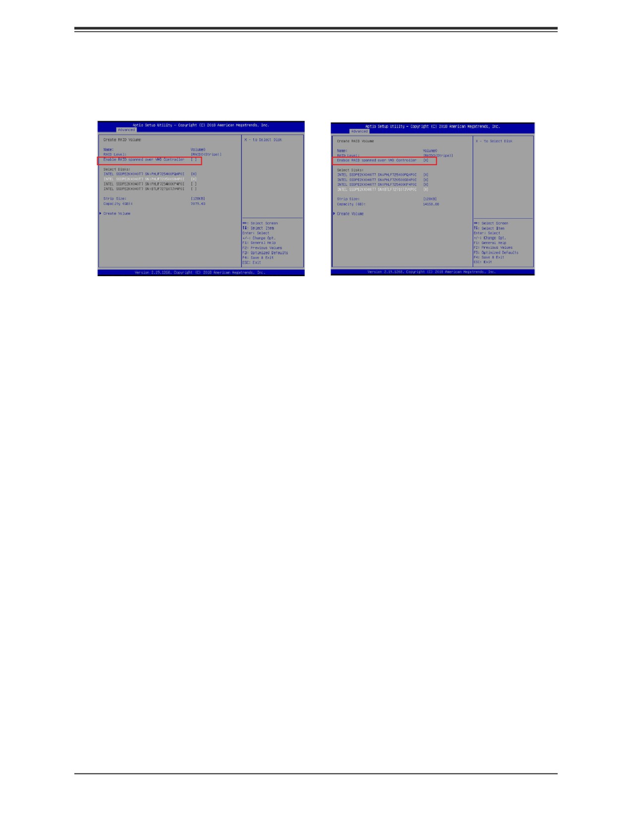
10. If cross-controller RAID is required, select Enable RAID spanned over VMD
Controller.
Figure 6-9-9. Created Volume without
Figure 9-10. Created Volume with
enabling RAID spanned over VMD
enabling RAID spanned over VMD
controller
controller
11.Select specific disks for RAID with an [X].
• RAID0: Select at least two [2 - 24] disks
• RAID1: Select only two disks
• RAID5: Select at least three [3 - 24] disks
• RAID10: Select only four disks
12. Select Strip Size (Default 64KB).
13. Select Create Volume.
14. If another RAID is needed, start again at step 9.
15. Press [F4] to save and reboot.
89
Chapter 9: Optional Components
Status Indications
An LED indicator on the drive carrier shows the RAID status of the drive.
Drive Carrier Status LED Indicator
Status
State (red)
Normal function
Off
Locating
4 Hz blink
Fault
Solid on
Rebuilding
1 Hz Blink
IBPI SFF 8489 Defined Status LED States
Hot Swap Drives
Intel VMD enables hot-plug and hot-unplug for NVMe SSDs, whether from Intel or other
manufacturers. Under vSphere ESXi, several steps are necessary to avoid potential stability
issues. See the information at link [1] below.
Hot-unplug
1. Prevent devices from being re-detected during rescan:
esxcli storage core claiming autoclaim --enabled=false
2. Unmount the VMFS volumes on the device. Check [2] for details.
3. Detach the device. Check [3] for details.
4. Physically remove the device.
Hot-plug
• Physically install the device.
ESXi will automatically discover NVMe SSDs, but a manual scan may be required in some
cases.
Related Information Links
GUID-1B56EF97-F60E-4F21-82A7-8F2A7294604D.html
GUID-F2E75F67-740B-4406-9F0C-A2D99A698F2A.html
90
Chapter 10: Troubleshooting and Support
Chapter 10
Troubleshooting and Support
10.1 Information Resources
Website
A great deal of information is available on the Supermicro website, supermicro.com.
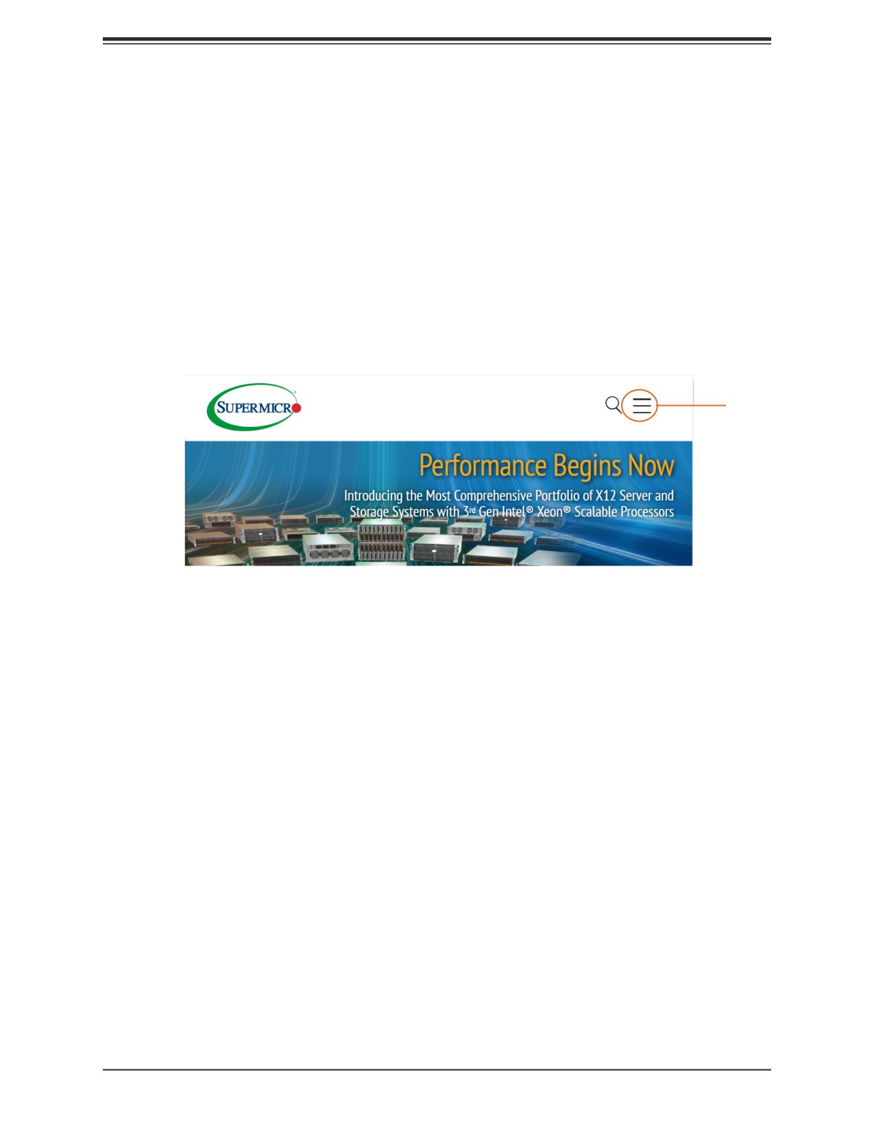
Menu
Icon'
Figure 10-1. Supermicro Website
Click the menu icon, the three bars in the upper right corner, then select:
• Specifications for servers and other hardware are available by clicking the Products option.
• The Support option offers downloads (manuals, BIOS/BMC, drivers, etc.), FAQs, RMA,
warranty, and other service extensions.
Direct Links for the SBS-820H-420P System
System SBS-820H-420P specifications page
Blade SBI-420P-1T3N specifications page
B12DPT-6 motherboard page for links to the Quick Reference Guide, User Manual, validated
storage drives, etc.
Direct Links for General Support and Information
Frequently Asked Questions
TPM User Guide
BMC User Guide
SuperDoctor5 Large Deployment Guide
91
Chapter 10: Troubleshooting and Support
Direct Links (continued)
For validated memory, use our Product Resources page
Product Matrices page for links to tables summarizing specs for systems, motherboards,
power supplies, riser cards, add-on cards, etc.
Security Center for recent security notices
Supermicro Phone and Addresses
10.2 BMC Interface
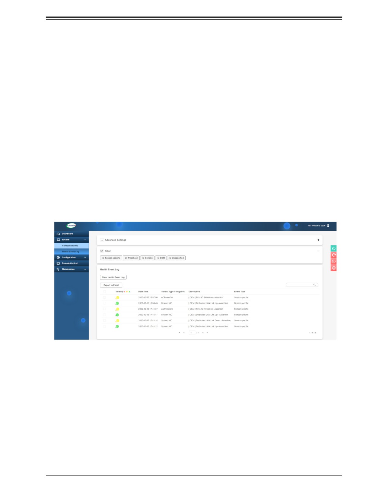
The system supports a Baseboard Management Controller (BMC) interface. It provides remote
access, monitoring and management. There are several BIOS settings related to the BMC.
For general documentation and information on the BMC, please visit our website at:
www.supermicro.com/manuals/other/BMC_Users_Guide_X12_H12.pdf.
Figure 10-2. BMC Dashboard Sample
92
Chapter 10: Troubleshooting and Support
10.3 Troubleshooting Procedures
Use the following procedures to troubleshoot your system. If you have followed all of the
procedures below and still need assistance, refer to the Technical Support Procedures or
Returning Merchandise for Service sections in this chapter. Power down the system before
changing any non hot-swap hardware components.
No Power
1. As you try to power up the system, note any beep codes. Refer to the next section for
details on beep codes.
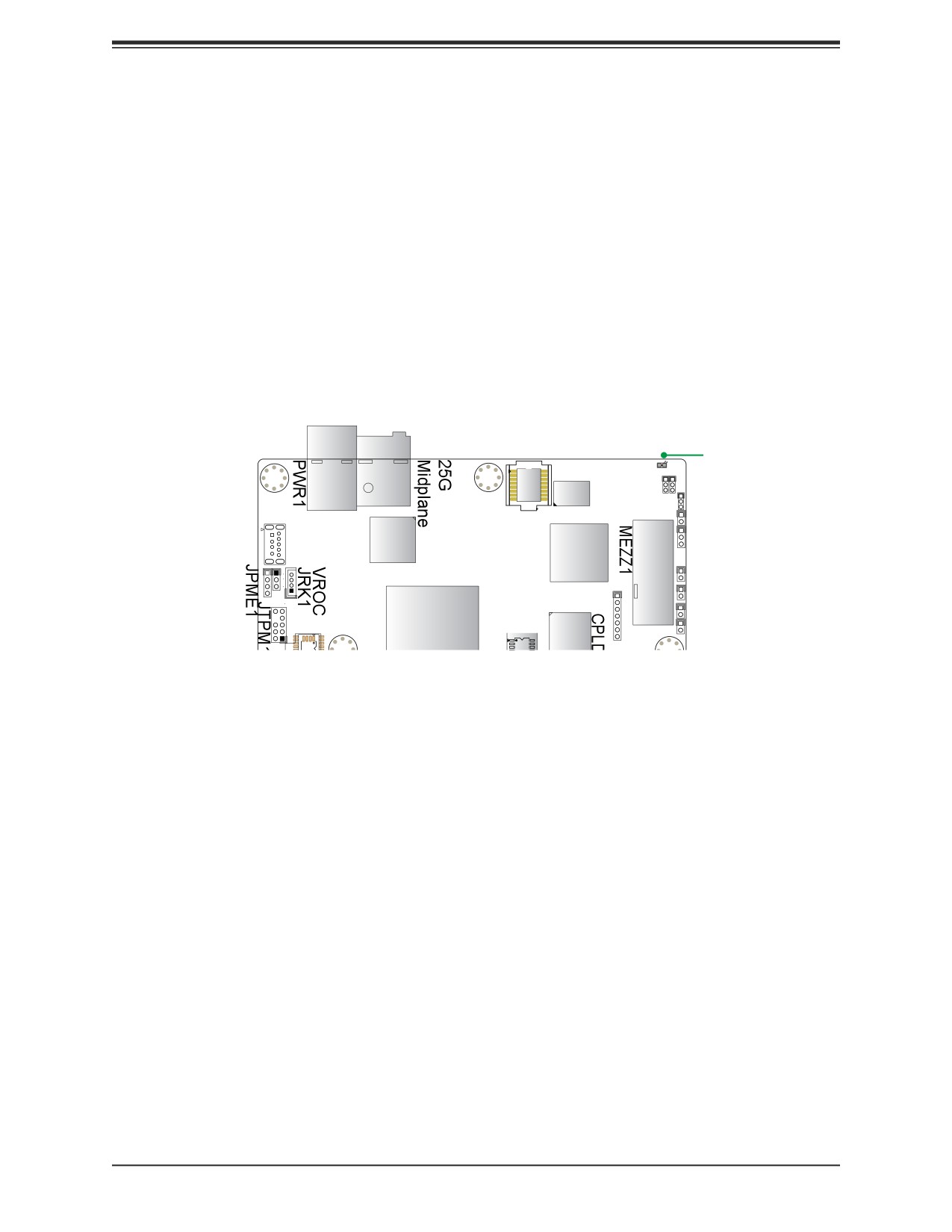
2. Check that the power LED on the motherboard is on.
MP1
LEDM1
LEDM1
BMC
Memory
MB PWR
BMC Flash
LAN CTRL
BMC
Dual Boot
for CPLD
Figure 10-3. Location of the MB Power LED
3. Make sure that the power connector is connected to your power supply.
4. Make sure that no short circuits exist between the motherboard and
chassis.
5. Disconnect all
cables from the motherboard, including those for the keyboard and mouse.
6. Remove all add-on cards.
7. Install a CPU,
a heatsink, connect the internal speaker (if applicable), and the power LED
to the motherboard. Make sure that the heatsink is fully seated.
8. Use the correct type of onboard CMOS battery as recommended by the manufacturer.
Check to verify that it still supplies ~3VDC. If it does not, replace
it with a new one.
Warning: To avoid possible explosion, do not install the battery upside down.
9. Verify that all jumpers are set to their default positions.
10. Check that the power supplies’ input voltage operate at 100-120v or 180-240v.
11.Turn the power switch on and off to test the system
93
Chapter 10: Troubleshooting and Support
No Video
1. If the power is on but you have no video, remove all the add-on cards and cables.
2. As you try to power up the system, note any beep codes. Refer to the next section for
details on beep codes.
System Boot Failure
If the system does not display POST (Power-On-Self-Test) or does not respond after the
power is turned on, check the following:
Turn on the system with only one DIMM module installed. If the system boots, check for bad
DIMM modules or slots by following the Memory Errors Troubleshooting procedure below.
Memory Errors
1. Make sure that the DIMM modules are properly and fully installed.
2. Confirm that you are using the correct memory. Also, it is recommended that you use the
same memory type and speed for all DIMMs in the system. See Section 3.3 for memory
details.
3. Check for bad DIMM modules or slots by swapping modules between slots and noting the
results.
4. Check the power supply voltage 115V/230V switch.
Losing the System Setup Configuration
1. Make sure that you are using a high quality power supply. A poor quality power supply may
cause the system to lose the CMOS setup information. .
2. The battery on your motherboard may be old. Check to verify that it still supplies ~3VDC.
If it does not, replace it with a new one.
3. If the above steps do not fix the setup configuration problem, contact your vendor for repairs.
When the System Becomes Unstable
If the system becomes unstable during or after OS installation, check the following:
1. CPU/BIOS support: Make sure that your CPU is supported and that you have the latest
BIOS installed in your system.
94
Chapter 10: Troubleshooting and Support
2. Memory support: Make sure that the memory modules are supported by testing the modules
using memtest86 or a similar utility.
and CPU support and updates.
3. HDD support: Make sure that all hard disk drives (HDDs) work properly. Replace the bad
HDDs with good ones.
4. System cooling: Check the system cooling to make sure that all heatsink fans and CPU/
system fans, etc., work properly. Check the hardware monitoring settings in the IPMI to
make sure that the CPU and system temperatures are within the normal range. Also check
the front panel Overheat LED and make sure that it is not on.
5. Adequate power supply: Make sure that the power supply provides adequate power to the
system. Make sure that all power connectors are connected. Please refer to our website
for more information on the minimum power requirements.
6. Proper software support: Make sure that the correct drivers are used.
If the system becomes unstable before or during OS installation, check the following:
1. Source of installation: Make sure that the devices used for installation are working properly,
including boot devices such as CD.
2. Cable connection: Check to make sure that all cables are connected and working properly.
3. Using the minimum configuration for troubleshooting: Remove all unnecessary components
(starting with add-on cards first), and use the minimum configuration (but with a CPU and a
memory module installed) to identify the trouble areas. Refer to the steps listed in Section
A above for proper troubleshooting procedures.
4. Identifying bad components by isolating them: If necessary, remove a component in
question from the chassis, and test it in isolation to make sure that it works properly.
Replace a bad component with a good one.
5. Check and change one component at a time instead of changing several items at the same
time. This will help isolate and identify the problem.
6. To find out if a component is good, swap this component with a new one to see if the
system will work properly. If so, then the old component is bad. You can also install the
component in question in another system. If the new system works, the component is good
and the old system has problems.
95
Chapter 10: Troubleshooting and Support
10.4 BIOS Error Beep (POST) Codes
During the POST (Power-On Self-Test) routines, which are performed each time the system
is powered on, errors may occur.
Non-fatal errors are those which, in most cases, allow the system to continue the boot-up
process. The error messages normally appear on the screen.
Fatal errors are those which will not allow the system to continue the boot-up procedure. If
a fatal error occurs, you should consult with your system manufacturer for possible repairs.
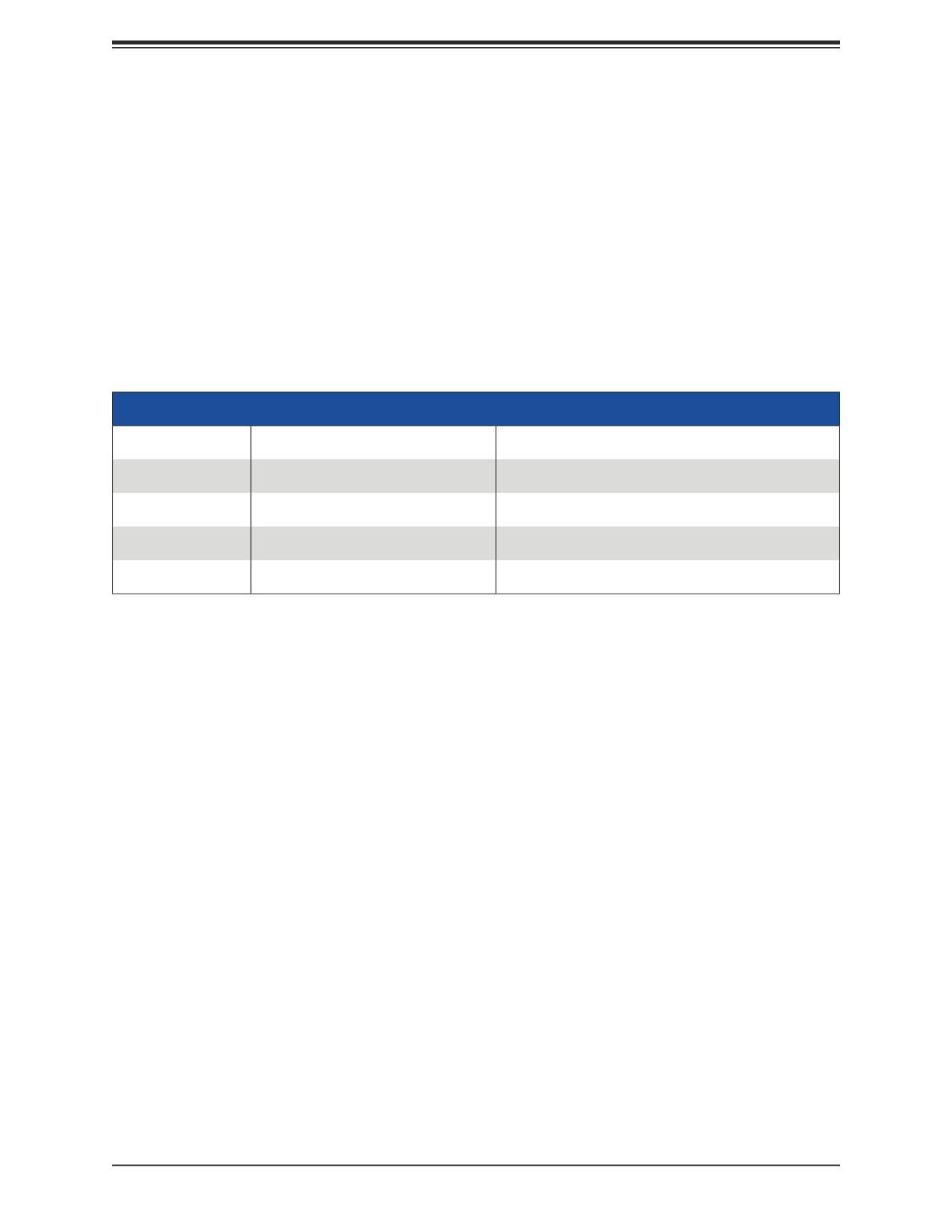
These fatal errors are usually communicated through a series of audible beeps. The table
below lists some common errors and their corresponding beep codes encountered by users.
BIOS Error Beep (POST) Codes
Beep Code
Error Message
Description
1 short
Refresh
Circuits have been reset (Ready to power up)
5 short, 1 long
Memory error
No memory detected in system
5 long, 2 short
Display memory read/write error
Video adapter missing or with faulty memory
1 long continuous
System OH
System overheat condition
Additional BIOS POST Codes
The AMI BIOS supplies additional checkpoint codes, which are documented online at http://
When BIOS performs the Power On Self Test, it writes checkpoint codes to I/O port 0080h.
If the computer cannot complete the boot process, a diagnostic card can be attached to the
computer to read I/O port 0080h (Supermicro p/n AOC-LPC80-20).
For information on AMI updates, please refer to http://www.ami.com/products/.
96
Chapter 10: Troubleshooting and Support
10.5 Crash Dump Using the BMC Dashboard
In the event of a processor internal error (IERR) that crashes your system, you may want to
provide information to support staff. You can download a crash dump of status information
using the BMC Dashboard. The BMC manual is available at www.supermicro.com/manuals/
other/BMC_Users_Guide_X12_H12.pdf.
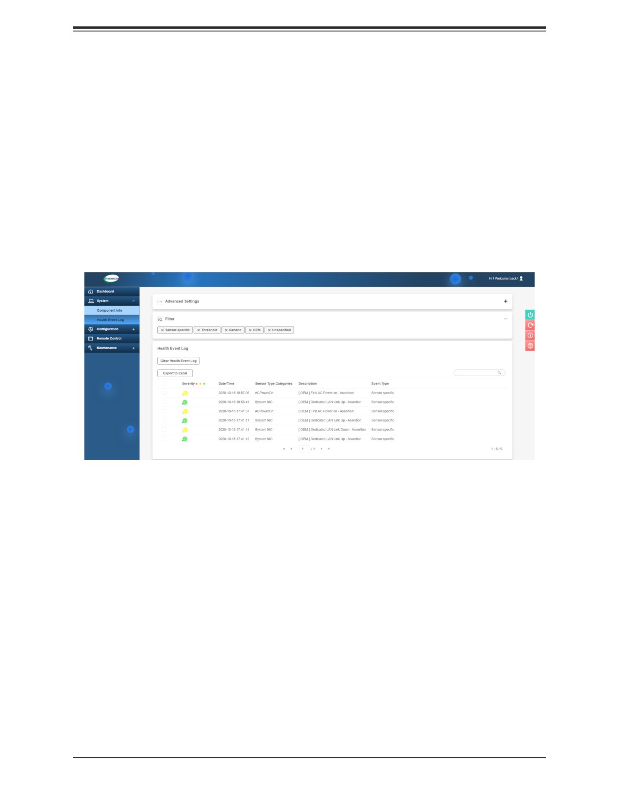
Check Error Log
1. Access the BMC web interface.
2. Click the Server Health tab, then Event Log to verify an IERR error.
Figure 10-4. BMC Event Log
In the event of an IERR, the BMC executes a crash dump. You must download the crash
dump and save it.
97
Chapter 10: Troubleshooting and Support
10.6 UEFI BIOS Recovery
Warning: Do not upgrade the BIOS unless your system has a BIOS-related issue. Flashing
the wrong BIOS can cause irreparable damage to the system. In no event shall Supermicro
be liable for direct, indirect, special, incidental, or consequential damages arising from a BIOS
update. If you do update the BIOS, do not shut down or reset the system while the BIOS is
updating to avoid possible boot failure.
Overview
The Unified Extensible Firmware Interface (UEFI) provides a software-based interface
between the operating system and the platform firmware in the pre-boot environment. The
UEFI specification supports an architecture-independent mechanism that will allow the UEFI
OS loader stored in an add-on card to boot the system. The UEFI offers clean, hands-off
management to a computer during system boot.
Recovering the UEFI BIOS Image
A UEFI BIOS flash chip consists of a recovery BIOS block and a main BIOS block (a main
BIOS image). The recovery block contains critical BIOS codes, including memory detection
and recovery codes for the user to flash a healthy BIOS image if the original main BIOS image
is corrupted. When the system power is turned on, the recovery block codes execute first.
Once this process is complete, the main BIOS code will continue with system initialization
and the remaining POST (Power-On Self-Test) routines.
Note 1: Follow the BIOS recovery instructions below for BIOS recovery when the main BIOS
block crashes.
Note 2: When the BIOS recovery block crashes, you will need to follow the procedures
to make a Returned Merchandise Authorization (RMA) request. Also, you may use the
Supermicro Update Manager (SUM) Out-of-Band (https://www.supermicro.com.tw/products/
nfo/SMS_SUM.cfm) to reflash the BIOS.
Recovering the Main BIOS Block with a USB Device
This feature allows the user to recover the main BIOS image using a USB-attached device
without additional utilities used. A USB flash device such as a USB Flash Drive, or a USB
CD/DVD ROM/RW device can be used for this purpose. However, a USB Hard Disk drive
cannot be used for BIOS recovery at this time.
The file system supported by the recovery block is FAT (including FAT12, FAT16, and FAT32)
which is installed on a bootable or non-bootable USB-attached device. However, the BIOS
might need several minutes to locate the SUPER.ROM file if the media size becomes too
large due to the huge volumes of folders and files stored in the device.
To perform UEFI BIOS recovery using a USB-attached device, follow the instructions below.
98
Chapter 10: Troubleshooting and Support
1. Using a different machine, copy the "Super.ROM" binary image file into the Root "\" directory
of a USB device or a writable CD/DVD.
Note 1: If you cannot locate the "Super.ROM" file in your drive disk, visit our website at
a USB flash device and rename it "Super.ROM" for the BIOS recovery use.
Note 2: Before recovering the main BIOS image, confirm that the "Super.ROM" binary
image file you download is the same version or a close version meant for your motherboard.
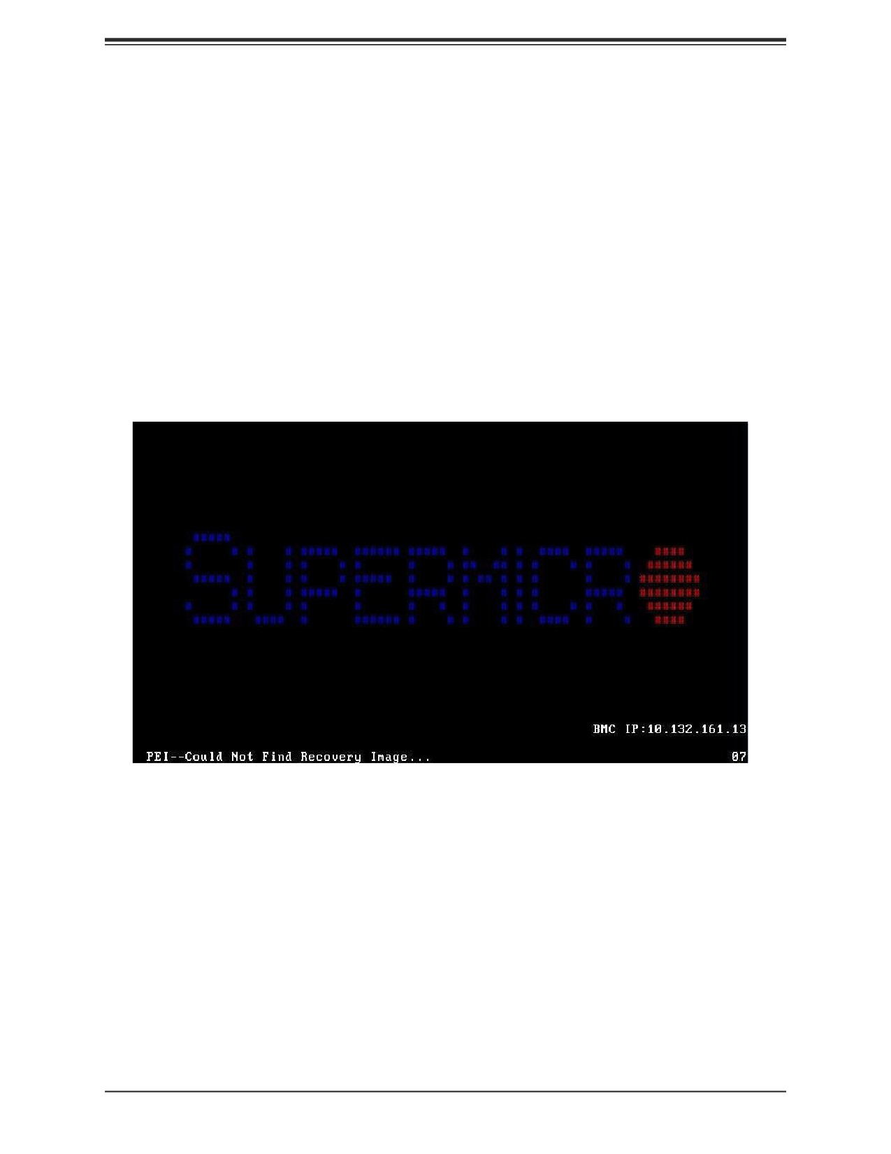
2. Insert the USB device that contains the new BIOS image ("Super.ROM") into your USB
drive and reset the system when the following screen appears.
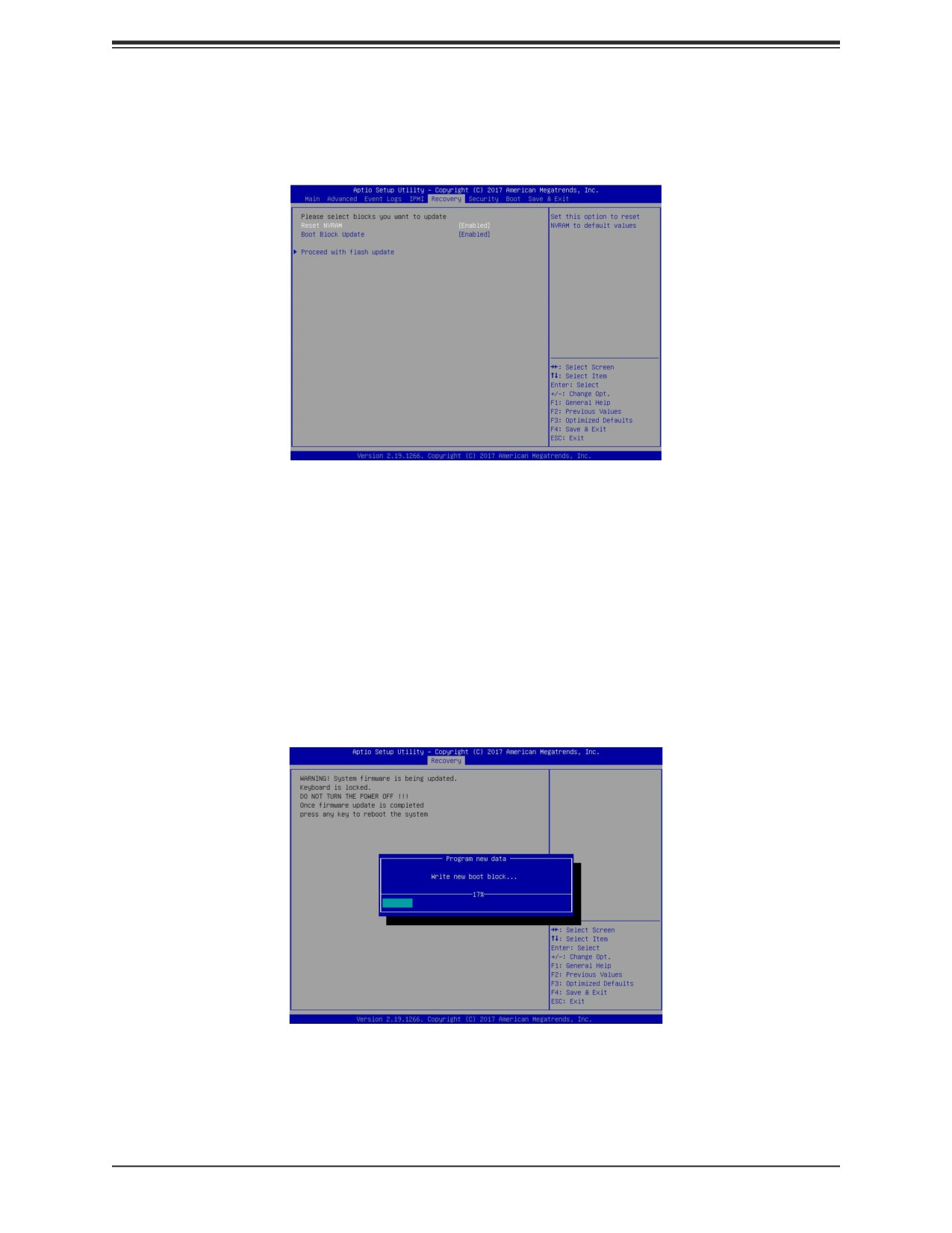
3. After locating the healthy BIOS binary image, the system will enter the BIOS Recovery
menu as shown below.
99
Chapter 10: Troubleshooting and Support
Note: At this point, you may decide if you want to start the BIOS recovery. If you decide
to proceed with BIOS recovery, follow the procedures below.
4. When the screen as shown above displays, use the arrow keys to select the item "Proceed
with flash update" and press the <Enter> key. You will see the BIOS recovery progress as
shown in the screen below.
Note: Do not interrupt the BIOS flashing process until it has completed.
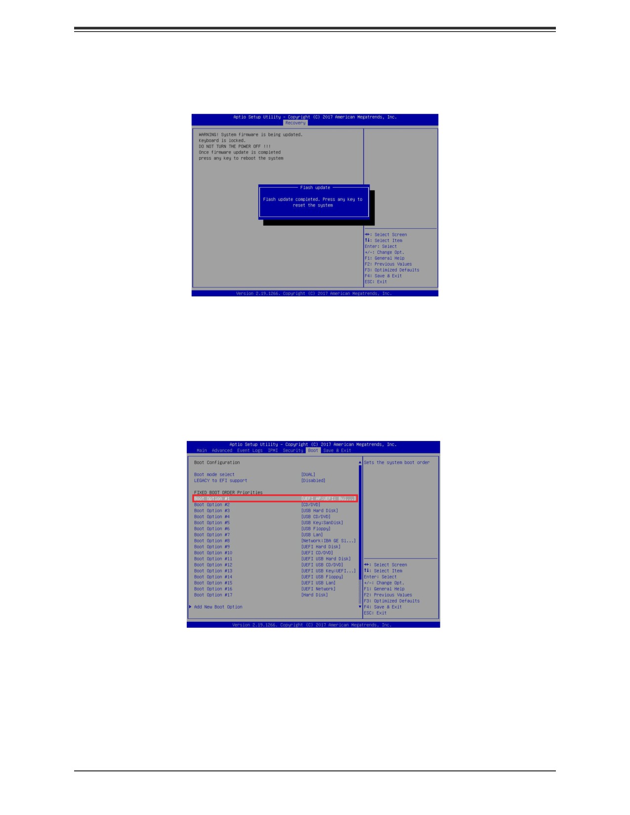
5. After the BIOS recovery process is complete, press any key to reboot the system.
6. Using a different system, extract the BIOS package into a USB flash drive.
100
Chapter 10: Troubleshooting and Support
7. Press <Del> continuously during system boot to enter the BIOS Setup utility. From the
top of the tool bar, select Boot to enter the submenu. From the submenu list, select Boot
Option #1 as shown below. Then, set Boot Option #1 to [UEFI AP:UEFI: Built-in EFI Shell].
Press <F4> to save the settings and exit the BIOS Setup utility.
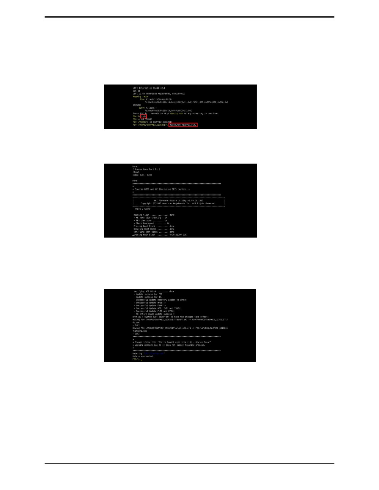
8. When the UEFI Shell prompt appears, type fs# to change the device directory path. Go
to the directory that contains the BIOS package you extracted earlier from Step 6. Enter
flash.nsh BIOSname.### at the prompt to start the BIOS update process.
101
Chapter 10: Troubleshooting and Support
Note: Do not interrupt this process until the BIOS flashing is complete.
9. The screen above indicates that the BIOS update process is complete. When you see the
screen above, unplug the AC power cable from the power supply, clear CMOS, and plug
the AC power cable in the power supply again to power on the system.
10. Press <Del> continuously to enter the BIOS Setup utility.
11. Press <F3> to load the default settings.
12. After loading the default settings, press <F4> to save the settings and exit the BIOS
Setup utility.
102
Chapter 10: Troubleshooting and Support
10.7 CMOS Clear
JBT1 is used to clear CMOS, which will also clear any passwords. Instead of pins, this jumper
consists of contact pads to prevent accidentally clearing the contents of CMOS.
To Clear CMOS
1. First power down the system completely.
2. Remove the onboard battery from the motherboard.
3. Short the CMOS pads with a metal object such as a small screwdriver for at least four
seconds.
4. Remove the screwdriver or shorting device.
JBT1 contact pads
5. Replace the cover, reconnect the power cords and power on the system.
Notes: Clearing CMOS will also clear all passwords.
Do not use the PW_ON connector to clear CMOS.
10.8 BMC Reset
The BMC can be reset using the UID button.
• Reset - Press and hold the button. After six seconds, the LED blinks at 2Hz. The BMC
resets and the reset duration is ~250 ms. Then the BMC starts to boot.
• Restore factory default configuration - Hold the button for twelve seconds. The LED blinks
at 4Hz while defaults are configured. Note: All BMC settings including username and
password will be removed except the FRU and network settings.
Firmware update - When the BMC firmware is being updated, the UID LED blinks at 10Hz.
BMC Reset Options
Event
UID LED
BMC Heartbeat LED
Reset
Blue, Blinks at 2Hz
Green, solid
Restore
Blue, Blinks at 4Hz
Off
Defaults
Update
Blue, Blinks at 10Hz
103
Chapter 10: Troubleshooting and Support
10.9 Where to Get Replacement Components
If you need replacement parts for your system, to ensure the highest level of professional
service and technical support, purchase exclusively from our Supermicro Authorized
Distributors/System Integrators/Resellers. A list can be found at: http://www.supermicro.com.
Click the "Where to Buy" tab.
10.10
Reporting an Issue
Technical Support Procedures
Before contacting Technical Support, please take the following steps. If your system was
purchased through a distributor or reseller, please contact them for troubleshooting services.
They have the best knowledge of your specific system configuration.
1. Please review the Troubleshooting Procedures in this manual and Frequently Asked
Questions on our website before contacting Technical Support.
2. BIOS upgrades can be downloaded from our website. Note: Not all BIOS can be flashed
depending on the modifications to the boot block code.
3. If you still cannot resolve the problem, include the following information when contacting
us for technical support:
• System, motherboard, and chassis model numbers and PCB revision number
• BIOS release date/version (this can be seen on the initial display when your system
first boots up)
• System configuration
An example of a Technical Support form is posted on our website. Distributors: For immediate
assistance, please have your account number ready when contacting our technical support
department by email.
Returning Merchandise for Service
A receipt or copy of your invoice marked with the date of purchase is required before any
warranty service will be rendered. You can obtain service by calling your vendor for a Returned
Merchandise Authorization (RMA) number. When returning to the manufacturer, the RMA
number should be prominently displayed on the outside of the shipping carton, and mailed
prepaid or hand-carried. Shipping and handling charges will be applied for all orders that
must be mailed when service is complete.
For faster service, RMA authorizations may be requested online (http://www.supermicro.com/
support/rma/).
104
Chapter 10: Troubleshooting and Support
Whenever possible, repack the chassis in the original Supermicro carton, using the original
packaging material. If these are no longer available, be sure to pack the chassis securely,
using packaging material to surround the chassis so that it does not shift within the carton
and become damaged during shipping.
This warranty only covers normal consumer use and does not cover damages incurred in
shipping or from failure due to the alteration, misuse, abuse or improper maintenance of
products.
During the warranty period, contact your distributor first for any product problems.
Vendor Support Filing System
For issues related to Intel, use the Intel IPS filing system:
For issues related to Red Hat Enterprise Linux, since it is a subscription based OS, contact
your account representative.
10.11
Feedback
Supermicro values your feedback as we strive to improve our customer experience in all facets
of our business. To provide feedback on our manuals, please email us at techwriterteam@
supermicro.com.
105
Chapter 10: Troubleshooting and Support
10.12
Contacting Supermicro
Headquarters
Address:
Super Micro Computer, Inc.
980 Rock Ave.
San Jose, CA 95131 U.S.A.
Tel:
+1 (408) 503-8000
Fax:
+1 (408) 503-8008
Email:
marketing@supermicro.com (General Information)
support@supermicro.com (Technical Support)
Website:
Europe
Address:
Super Micro Computer B.V.
Het Sterrenbeeld 28, 5215 ML
's-Hertogenbosch, The Netherlands
Tel:
+31 (0) 73-6400390
Fax:
+31 (0) 73-6416525
Email:
sales@supermicro.nl (General Information)
support@supermicro.nl (Technical Support)
rma@supermicro.nl (Customer Support)
Website:
Asia-Pacific
Address:
Super Micro Computer, Inc.
3F, No. 150, Jian 1st Rd.
Zhonghe Dist., New Taipei City 235
Taiwan (R.O.C)
Tel:
+8810-(2) 82210-3990
Fax:
+8810-(2) 82210-3992
Email:
support@supermicro.com.tw
Website:
106
Appendix A: Warning Statements
Appendix A
Standardized Warning Statements for AC
Systems
About Standardized Warning Statements
The following statements are industry standard warnings, provided to warn the user of
situations which have the potential for bodily injury. Should you have questions or experience
difficulty, contact Supermicro's Technical Support department for assistance. Only certified
technicians should attempt to install or configure components.
Read this appendix in its entirety before installing or configuring components in the Supermicro
chassis.
These warnings may also be found on our website at http://www.supermicro.com/about/
policies/safety_information.cfm.
Warning Definition
Warning! This warning symbol means danger. You are in a situation that could cause
bodily injury. Before you work on any equipment, be aware of the hazards involved
with electrical circuitry and be familiar with standard practices for preventing accidents.
警告の定義
この警告サインは危険を意味します。
人身事故につながる可能性がありますので、いずれの機器でも動作させる前に、
電気回路に含まれる危険性に注意して、標準的な事故防止策に精通して下さい。
此警告符号代表危险。
您正处于可能受到严重伤害的工作环境中。在您使用设备开始工作之前,必须充分意识到触电
的危险,并熟练掌握防止事故发生的标准工作程序。请根据每项警告结尾的声明号码找到此设
备的安全性警告说明的翻译文本。
此警告符號代表危險。
您正處於可能身體可能會受損傷的工作環境中。在您使用任何設備之前,請注意觸電的危險,
並且要熟悉預防事故發生的標準工作程序。請依照每一注意事項後的號碼找到相關的翻譯說明
內容。
107
Appendix A: Warning Statements
Warnung
WICHTIGE SICHERHEITSHINWEISE
Dieses Warnsymbol bedeutet Gefahr. Sie befinden sich in einer Situation, die zu Verletzungen
führen kann. Machen Sie sich vor der Arbeit mit Geräten mit den Gefahren elektrischer
Schaltungen und den üblichen Verfahren zur Vorbeugung vor Unfällen vertraut. Suchen
Sie mit der am Ende jeder Warnung angegebenen Anweisungsnummer nach der jeweiligen
Übersetzung in den übersetzten Sicherheitshinweisen, die zusammen mit diesem Gerät
ausgeliefert wurden.
BEWAHREN SIE DIESE HINWEISE GUT AUF.
INSTRUCCIONES IMPORTANTES DE SEGURIDAD
Este símbolo de aviso indica peligro. Existe riesgo para su integridad física. Antes de
manipular cualquier equipo, considere los riesgos de la corriente eléctrica y familiarícese
con los procedimientos estándar de prevención de accidentes. Al final de cada advertencia
encontrará el número que le ayudará a encontrar el texto traducido en el apartado de
traducciones que acompaña a este dispositivo.
GUARDE ESTAS INSTRUCCIONES.
IMPORTANTES INFORMATIONS DE SÉCURITÉ
Ce symbole d'avertissement indique un danger. Vous vous trouvez dans une situation pouvant
entraîner des blessures ou des dommages corporels. Avant de travailler sur un équipement,
soyez conscient des dangers liés aux circuits électriques et familiarisez-vous avec les
procédures couramment utilisées pour éviter les accidents. Pour prendre connaissance
des traductions des avertissements figurant dans les consignes de sécurité traduites qui
accompagnent cet appareil, référez-vous au numéro de l'instruction situé à la fin de chaque
avertissement.
CONSERVEZ CES INFORMATIONS.
הרהזא תורהצה ןונקת
הלבח ינפמ שמתשמה תא ריהזהל תנמ לע ,היישעתה ינקת יפ לע תורהזא ןה תואבה תורהצה
הכימת תקלחמ םע רשק רוציל שי ,יהשלכ היעבב תולקתיה וא תולאש שיו הדימב .תירשפא תיזיפ
.םיביכרה תא רידגהל וא ןיקתהל םיאשר דבלב םיכמסומ םיאנכט .ורקימרפוס לש תינכט
.ורקימרפוס יזראמב םיביכרה תרדגה וא תנקתה ינפל ואולמב חפסנה תא אורקל שי
108
Appendix A: Warning Statements
. ز ذحت! زطخ ع زهزلا اذه ة ذسج ةباصا ف ببستت ىأ كو ةلاح ف ك ا
زئاوذلا يع ةوجا لا زطاخولاب نلع لع ك،تاذعه يأ لع لوعت ىأ لبق
ة ئابزهكلا
ثداىح يأ عىقو ع ول ة ئاقىلا تاسراوولاب ة ارد لع كو
اهتوجزت رىثعلل ز ذحت لك ة اه ف صىص ولا ىا بلا نقر مذختسا
안전을 위한 주의사항
경고!
이 경고 기호는 위험이 있음을 알려 줍니다. 작업자의 신체에 부상을 야기 할 수 있는
상태에 있게 됩니다. 모든 장비에 대한 작업을 수행하기 전에 전기회로와 관련된
위험요소들을 확인하시고 사전에 사고를 방지할 수 있도록 표준 작업절차를 준수해 주시기
바랍니다.
해당 번역문을 찾기 위해 각 경고의 마지막 부분에 제공된 경고문 번호를 참조하십시오
BELANGRIJKE VEILIGHEIDSINSTRUCTIES
Dit waarschuwings symbool betekent gevaar. U verkeert in een situatie die lichamelijk letsel
kan veroorzaken. Voordat u aan enige apparatuur gaat werken, dient u zich bewust te zijn
van de bij een elektrische installatie betrokken risico's en dient u op de hoogte te zijn van de
standaard procedures om ongelukken te voorkomen. Gebruik de nummers aan het eind van
elke waarschuwing om deze te herleiden naar de desbetreffende locatie.
BEWAAR DEZE INSTRUCTIES
Installation Instructions
Warning! Read the installation instructions before connecting the system to the power
source.
設置手順書
システムを電源に接続する前に、設置手順書をお読み下さい。
警告
将此系统连接电源前,请先阅读安装说明。
警告
將系統與電源連接前,請先閱讀安裝說明。
109
Appendix A: Warning Statements
Warnung
Vor dem Anschließen des Systems an die Stromquelle die Installationsanweisungen lesen.
¡Advertencia!
Lea las instrucciones de instalación antes de conectar el sistema a la red de alimentación.
Attention
Avant de brancher le système sur la source d'alimentation, consulter les directives d'installation.
.חתמ רוקמל תכרעמה רוביח ינפל הנקתה תוארוה תא אורקל שי
ةقاطلل ردصم لإ ماظنلا ليصوت لبق بيكتلا تاداشرإ رقا
시스템을 전원에 연결하기 전에 설치 안내를 읽어주십시오.
Waarschuwing
Raadpleeg de installatie-instructies voordat u het systeem op de voedingsbron aansluit.
Circuit Breaker
Warning! This product relies on the building's installation for short-circuit (overcurrent)
protection. Ensure that the protective device is rated not greater than: 250 V, 20 A.
サーキット・ブレーカー
この製品は、短絡(過電流)保護装置がある建物での設置を前提としています。
保護装置の定格が250 V、20 Aを超えないことを確認下さい。
警告
此产品的短路(过载电流)保护由建筑物的供电系统提供,确保短路保护设备的额定电流不大于
250V,20A。
警告
此產品的短路(過載電流)保護由建築物的供電系統提供,確保短路保護設備的額定電流不大於
250V,20A。
110
Appendix A: Warning Statements
Warnung
Dieses Produkt ist darauf angewiesen, dass im Gebäude ein Kurzschluss- bzw.
Überstromschutz installiert ist. Stellen Sie sicher, dass der Nennwert der Schutzvorrichtung
nicht mehr als: 250 V, 20 A beträgt.
¡Advertencia!
Este equipo utiliza el sistema de protección contra cortocircuitos (o sobrecorrientes) del
edificio. Asegúrese de que el dispositivo de protección no sea superior a: 250 V, 20 A.
Attention
Pour ce qui est de la protection contre les courts-circuits (surtension), ce produit dépend de
l'installation électrique du local. Vérifiez que le courant nominal du dispositif de protection
n'est pas supérieur à :250 V, 20 A.
יכ אדוול שי .ילמשח רצק תעינמל םינבמב תנקתומה הנגה לע ךמתסמ הז רצומ
250VDC, 20A-מ רתוי אל אוה ילמשחה רצקה ינפמ ןגמה רישכמה
ف اهتيبثت مت يتلا ةيصقلارئاودلا هم تيمحلا ثادعم لع دمتعي جتنلا اذه
ىنبلا
20A, 250V : نم ثكأ سيل ئاقولا زاهجلا مييقت نأ نم دكأت
경고!
이 제품은 전원의 단락(과전류)방지에 대해서 전적으로 건물의 관련 설비에 의존합니다.
보호장치의 정격이 반드시 250V(볼트), 20A(암페어)를 초과하지 않도록 해야 합니다.
Waarschuwing
Dit product is afhankelijk van de kortsluitbeveiliging (overspanning) van uw electrische
installatie. Controleer of het beveiligde aparaat niet groter gedimensioneerd is dan 250V, 20A.
111
Appendix A: Warning Statements
Power Disconnection Warning
Warning! The system must be disconnected from all sources of power and the power
cord removed from the power supply module(s) before accessing the chassis interior
to install or remove system components.
電源切断の警告
システムコンポーネントの取り付けまたは取り外しのために、シャーシー内部にアクセスするには、
システムの電源はすべてのソースから切断され、電源コードは電源モジュールから取り外す必要が
あります。
警告
在你打开机箱并安装或移除内部器件前,必须将系统完全断电,并移除电源线。
警告
在您打開機殼安裝或移除內部元件前,必須將系統完全斷電,並移除電源線。
Warnung
Das System muss von allen Quellen der Energie und vom Netzanschlusskabel getrennt sein,
das von den Spg.Versorgungsteilmodulen entfernt wird, bevor es auf den Chassisinnenraum
zurückgreift, um Systemsbestandteile anzubringen oder zu entfernen.
¡Advertencia!
El sistema debe ser disconnected de todas las fuentes de energía y del cable eléctrico quitado
de los módulos de fuente de alimentación antes de tener acceso el interior del chasis para
instalar o para quitar componentes de sistema.
Attention
Le système doit être débranché de toutes les sources de puissance ainsi que de son cordon
d'alimentation secteur avant d'accéder à l'intérieur du chassis pour installer ou enlever des
composants de systéme.
112
Appendix A: Warning Statements
ילמשח קותינ ינפמ הרהזא
הרהזא!
קפסהמ ילמשחה לבכ תא ריסהל שיו למשחה תורוקמ לכמ תכרעמה תא קתנל שי
םיביכר תרסה וא תנקתה ךרוצל זראמה לש ימינפה קלחל השיג ינפל.
دادما ةدحو نم ءابرهكنا كهس تنازإو تقاطنا رداصم عيمج نم واظننا مصف بجي
مبق تقاطنا
زاهجلا ثانىكم تنازإ وأ جيبثتن مكيههن تيهخادنا قطاننا نإ لىصىنا
경고!
시스템에 부품들을 장착하거나 제거하기 위해서는 섀시 내부에 접근하기 전에 반드시 전원
공급장치로부터 연결되어있는 모든 전원과 전기코드를 분리해주어야 합니다.
Waarschuwing
Voordat u toegang neemt tot het binnenwerk van de behuizing voor het installeren of
verwijderen van systeem onderdelen, dient u alle spanningsbronnen en alle stroomkabels
aangesloten op de voeding(en) van de behuizing te verwijderen
Equipment Installation
Warning! Only trained and qualified personnel should be allowed to install, replace,
or service this equipment.
機器の設置
トレーニングを受け認定された人だけがこの装置の設置、交換、またはサービスを許可されていま
す。
警告
只有经过培训且具有资格的人员才能进行此设备的安装、更换和维修。
警告
只有經過受訓且具資格人員才可安裝、更換與維修此設備。
Warnung
Das Installieren, Ersetzen oder Bedienen dieser Ausrüstung sollte nur geschultem,
qualifiziertem Personal gestattet werden.
113
Appendix A: Warning Statements
¡Advertencia!
Solamente el personal calificado debe instalar, reemplazar o utilizar este equipo.
Attention
Il est vivement recommandé de confier l'installation, le remplacement et la maintenance de
ces équipements à des personnels qualifiés et expérimentés.
!הרהזא
.דויצה רובע תוריש תתל וא דויצה תא ףילחהל ,ןיקתהל יאשר דבלב ךמסומ תווצ
هيلهؤلا هيفظىملل طقف حمسي نأ بجي ساهجلا اذه ةمدخ وأ لادبتساو بيكزتل هيبردلاو
경고!
훈련을 받고 공인된 기술자만이 이 장비의 설치, 교체 또는 서비스를 수행할 수 있습니다.
Waarschuwing
Deze apparatuur mag alleen worden geïnstalleerd, vervangen of hersteld door geschoold en
gekwalificeerd personeel.
Restricted Area
Warning! This unit is intended for installation in restricted access areas. A restricted
access area can be accessed only through the use of a special tool, lock and key, or
other means of security. (This warning does not apply to workstations).
アクセス制限区域
このユニットは、アクセス制限区域に設置されることを想定しています。
アクセス制限区域は、特別なツール、鍵と錠前、その他のセキュリティの手段を用いてのみ出入りが
可能です。
警告
此部件应安装在限制进出的场所,限制进出的场所指只能通过使用特殊工具、锁和钥匙或其它
安全手段进出的场所。
警告
此裝置僅限安裝於進出管制區域,進出管制區域係指僅能以特殊工具、鎖頭及鑰匙或其他安全
方式才能進入的區域。
114
Appendix A: Warning Statements
Warnung
Diese Einheit ist zur Installation in Bereichen mit beschränktem Zutritt vorgesehen. Der Zutritt
zu derartigen Bereichen ist nur mit einem Spezialwerkzeug, Schloss und Schlüssel oder einer
sonstigen Sicherheitsvorkehrung möglich.
¡Advertencia!
Esta unidad ha sido diseñada para instalación en áreas de acceso restringido. Sólo puede
obtenerse acceso a una de estas áreas mediante la utilización de una herramienta especial,
cerradura con llave u otro medio de seguridad.
Attention
Cet appareil doit être installée dans des zones d'accès réservés. L'accès à une zone d'accès
réservé n'est possible qu'en utilisant un outil spécial, un mécanisme de verrouillage et une
clé, ou tout autre moyen de sécurité.
תלבגומ השיג םע רוזא
!הרהזא
תרזעב תנתינ השיגה .השיג תלבגה םהב שיש םירוזאב הדיחיה תא ןיקתהל שי
(.דכו לוענמ ,חתפמ) דבלב החטבא ילכ'
. مت ةروظحم قطانم ف اهب كرتن ةذحىنا هذه صيصخت
تصاخ ةادأ واذختسا للخ نم طقف ةروظحم تقطنم نإ لىصىنا نكم،
حاتفمو مفق اممللن يرخأ ته سو أ وأ
경고!
이 장치는 접근이 제한된 구역에 설치하도록 되어있습니다. 특수도구, 잠금 장치 및 키,
또는 기타 보안 수단을 통해서만 접근 제한 구역에 들어갈 수 있습니다.
Waarschuwing
Dit apparaat is bedoeld voor installatie in gebieden met een beperkte toegang. Toegang tot
dergelijke gebieden kunnen alleen verkregen worden door gebruik te maken van speciaal
gereedschap, slot en sleutel of andere veiligheidsmaatregelen.
115
Appendix A: Warning Statements
Battery Handling
Warning! There is the danger of explosion if the battery is replaced incorrectly. Replace
the battery only with the same or equivalent type recommended by the manufacturer.
Dispose of used batteries according to the manufacturer's instructions
電池の取り扱い
電池交換が正しく行われなかった場合、破裂の危険性があります。交換する電池はメーカーが推
奨する型、または同等のものを使用下さい。使用済電池は製造元の指示に従って処分して下さい。
警告
电池更换不当会有爆炸危险。请只使用同类电池或制造商推荐的功能相当的电池更换原有电
池。请按制造商的说明处理废旧电池。
警告
電池更換不當會有爆炸危險。請使用製造商建議之相同或功能相當的電池更換原有電池。請按
照製造商的說明指示處理廢棄舊電池。
Warnung
Bei Einsetzen einer falschen Batterie besteht Explosionsgefahr. Ersetzen Sie die Batterie nur
durch den gleichen oder vom Hersteller empfohlenen Batterietyp. Entsorgen Sie die benutzten
Batterien nach den Anweisungen des Herstellers.
Attention
Danger d'explosion si la pile n'est pas remplacée correctement. Ne la remplacer que par une
pile de type semblable ou équivalent, recommandée par le fabricant. Jeter les piles usagées
conformément aux instructions du fabricant.
¡Advertencia!
Existe peligro de explosión si la batería se reemplaza de manera incorrecta. Reemplazar la
batería exclusivamente con el mismo tipo o el equivalente recomendado por el fabricante.
Desechar las baterías gastadas según las instrucciones del fabricante.
!הרהזא
ףילחהל שי .הניקת אל ךרדב הפלחוהו הדימב הללוסה לש ץוציפ תנכס תמייק
.תצלמומ ןרצי תרבחמ םאותה גוסב הללוסה תא
.ןרציה תוארוה יפל עצבל שי תושמושמה תוללוסה קוליס
116
Appendix A: Warning Statements
ليلعف ةحيحص يغ ةقيرطب ةيراطبلا لاذبحسا ةلاح ف راجفنا نم رطخ كانه
ةيراطبلا لاذبحسا
ةعنصلا ةمشلا هب ثصوأ مم اهلداعي ام وأ عىنلا سفنب طقف
ةعناصلا ةمشلا تميلعحل اقفو ةلمعحسلا تايراطبلا نم صلخج
경고!
배터리가 올바르게 교체되지 않으면 폭발의 위험이 있습니다. 기존 배터리와 동일하거나 제
조사에서 권장하는 동등한 종류의 배터리로만 교체해야 합니다. 제조사의 안내에 따라 사용
된 배터리를 처리하여 주십시오.
Waarschuwing
Er is ontploffingsgevaar indien de batterij verkeerd vervangen wordt. Vervang de batterij
slechts met hetzelfde of een equivalent type die door de fabrikant aanbevolen wordt. Gebruikte
batterijen dienen overeenkomstig fabrieksvoorschriften afgevoerd te worden.
Redundant Power Supplies
Warning! This unit might have more than one power supply connection. All connec-
tions must be removed to de-energize the unit.
冗長電源装置
このユニットは複数の電源装置が接続されている場合があります。
ユニットの電源を切るためには、すべての接続を取り外さなければなりません。
警告
此部件连接的电源可能不止一个,必须将所有电源断开才能停止给该部件供电。
警告
此裝置連接的電源可能不只一個,必須切斷所有電源才能停止對該裝置的供電。
Warnung
Dieses Gerät kann mehr als eine Stromzufuhr haben. Um sicherzustellen, dass der Einheit
kein trom zugeführt wird, müssen alle Verbindungen entfernt werden.
117
Appendix A: Warning Statements
¡Advertencia!
Puede que esta unidad tenga más de una conexión para fuentes de alimentación. Para cortar
por completo el suministro de energía, deben desconectarse todas las conexiones.
Attention
Cette unité peut avoir plus d'une connexion d'alimentation. Pour supprimer toute tension et tout
courant électrique de l'unité, toutes les connexions d'alimentation doivent être débranchées.
דחא קפסמ רתוי םייק םא
!הרהזא
ןקורל תנמ לע םירוביחה לכ תא ריסהל שי .קפס לש דחא רוביחמ רתוי שי הדחיל
.הדיחיה תא
. ةقاطلا دادما تادحوب تلاصتا ةدع زاهجلا اذهل نوكي دق
ءابرهكلا نع ةدحولا لسعل تلاصتلا ةفاك ةلازإ بجي
경고!
이 장치에는 한 개 이상의 전원 공급 단자가 연결되어 있을 수 있습니다. 이 장치에 전원을
차단하기 위해서는 모든 연결 단자를 제거해야만 합니다.
Waarschuwing
Deze eenheid kan meer dan één stroomtoevoeraansluiting bevatten. Alle aansluitingen dienen
verwijderd te worden om het apparaat stroomloos te maken.
118
Appendix A: Warning Statements
Backplane Voltage
Warning! Hazardous voltage or energy is present on the backplane when the system
is operating. Use caution when servicing.
バックプレーンの電圧
システムの稼働中は危険な電圧または電力が、バックプレーン上にかかっています。
修理する際には注意ください。
警告
当系统正在进行时,背板上有很危险的电压或能量,进行维修时务必小心。
警告
當系統正在進行時,背板上有危險的電壓或能量,進行維修時務必小心。
Warnung
Wenn das System in Betrieb ist, treten auf der Rückwandplatine gefährliche Spannungen
oder Energien auf. Vorsicht bei der Wartung.
¡Advertencia!
Cuando el sistema está en funcionamiento, el voltaje del plano trasero es peligroso. Tenga
cuidado cuando lo revise.
Attention
Lorsque le système est en fonctionnement, des tensions électriques circulent sur le fond de
panier. Prendre des précautions lors de la maintenance.
ירוחאה לנפב חתמ
!הרהזא
ךלהמב רהזיהל שי .תכרעמה לועפת ןמזב ירוחאה לנפב חתמ תנכס תמייק
.הדובעה
119